EP2214712B1 - Compositions et procédés de traitement d'asthme et de troubles pulmonaires - Google Patents
Compositions et procédés de traitement d'asthme et de troubles pulmonaires Download PDFInfo
- Publication number
- EP2214712B1 EP2214712B1 EP08841984.1A EP08841984A EP2214712B1 EP 2214712 B1 EP2214712 B1 EP 2214712B1 EP 08841984 A EP08841984 A EP 08841984A EP 2214712 B1 EP2214712 B1 EP 2214712B1
- Authority
- EP
- European Patent Office
- Prior art keywords
- fluid
- lung
- rotor
- oxygen
- asthma
- Prior art date
- Legal status (The legal status is an assumption and is not a legal conclusion. Google has not performed a legal analysis and makes no representation as to the accuracy of the status listed.)
- Not-in-force
Links
Images


Classifications
-
- C—CHEMISTRY; METALLURGY
- C12—BIOCHEMISTRY; BEER; SPIRITS; WINE; VINEGAR; MICROBIOLOGY; ENZYMOLOGY; MUTATION OR GENETIC ENGINEERING
- C12N—MICROORGANISMS OR ENZYMES; COMPOSITIONS THEREOF; PROPAGATING, PRESERVING, OR MAINTAINING MICROORGANISMS; MUTATION OR GENETIC ENGINEERING; CULTURE MEDIA
- C12N13/00—Treatment of microorganisms or enzymes with electrical or wave energy, e.g. magnetism, sonic waves
-
- A—HUMAN NECESSITIES
- A61—MEDICAL OR VETERINARY SCIENCE; HYGIENE
- A61K—PREPARATIONS FOR MEDICAL, DENTAL OR TOILETRY PURPOSES
- A61K33/00—Medicinal preparations containing inorganic active ingredients
-
- A—HUMAN NECESSITIES
- A61—MEDICAL OR VETERINARY SCIENCE; HYGIENE
- A61K—PREPARATIONS FOR MEDICAL, DENTAL OR TOILETRY PURPOSES
- A61K45/00—Medicinal preparations containing active ingredients not provided for in groups A61K31/00 - A61K41/00
- A61K45/06—Mixtures of active ingredients without chemical characterisation, e.g. antiphlogistics and cardiaca
-
- A—HUMAN NECESSITIES
- A61—MEDICAL OR VETERINARY SCIENCE; HYGIENE
- A61P—SPECIFIC THERAPEUTIC ACTIVITY OF CHEMICAL COMPOUNDS OR MEDICINAL PREPARATIONS
- A61P11/00—Drugs for disorders of the respiratory system
-
- A—HUMAN NECESSITIES
- A61—MEDICAL OR VETERINARY SCIENCE; HYGIENE
- A61P—SPECIFIC THERAPEUTIC ACTIVITY OF CHEMICAL COMPOUNDS OR MEDICINAL PREPARATIONS
- A61P11/00—Drugs for disorders of the respiratory system
- A61P11/02—Nasal agents, e.g. decongestants
-
- A—HUMAN NECESSITIES
- A61—MEDICAL OR VETERINARY SCIENCE; HYGIENE
- A61P—SPECIFIC THERAPEUTIC ACTIVITY OF CHEMICAL COMPOUNDS OR MEDICINAL PREPARATIONS
- A61P11/00—Drugs for disorders of the respiratory system
- A61P11/06—Antiasthmatics
-
- A—HUMAN NECESSITIES
- A61—MEDICAL OR VETERINARY SCIENCE; HYGIENE
- A61P—SPECIFIC THERAPEUTIC ACTIVITY OF CHEMICAL COMPOUNDS OR MEDICINAL PREPARATIONS
- A61P11/00—Drugs for disorders of the respiratory system
- A61P11/08—Bronchodilators
-
- A—HUMAN NECESSITIES
- A61—MEDICAL OR VETERINARY SCIENCE; HYGIENE
- A61P—SPECIFIC THERAPEUTIC ACTIVITY OF CHEMICAL COMPOUNDS OR MEDICINAL PREPARATIONS
- A61P11/00—Drugs for disorders of the respiratory system
- A61P11/14—Antitussive agents
-
- A—HUMAN NECESSITIES
- A61—MEDICAL OR VETERINARY SCIENCE; HYGIENE
- A61P—SPECIFIC THERAPEUTIC ACTIVITY OF CHEMICAL COMPOUNDS OR MEDICINAL PREPARATIONS
- A61P31/00—Antiinfectives, i.e. antibiotics, antiseptics, chemotherapeutics
- A61P31/04—Antibacterial agents
-
- A—HUMAN NECESSITIES
- A61—MEDICAL OR VETERINARY SCIENCE; HYGIENE
- A61P—SPECIFIC THERAPEUTIC ACTIVITY OF CHEMICAL COMPOUNDS OR MEDICINAL PREPARATIONS
- A61P31/00—Antiinfectives, i.e. antibiotics, antiseptics, chemotherapeutics
- A61P31/12—Antivirals
- A61P31/14—Antivirals for RNA viruses
- A61P31/16—Antivirals for RNA viruses for influenza or rhinoviruses
-
- A—HUMAN NECESSITIES
- A61—MEDICAL OR VETERINARY SCIENCE; HYGIENE
- A61P—SPECIFIC THERAPEUTIC ACTIVITY OF CHEMICAL COMPOUNDS OR MEDICINAL PREPARATIONS
- A61P37/00—Drugs for immunological or allergic disorders
- A61P37/08—Antiallergic agents
-
- A—HUMAN NECESSITIES
- A61—MEDICAL OR VETERINARY SCIENCE; HYGIENE
- A61P—SPECIFIC THERAPEUTIC ACTIVITY OF CHEMICAL COMPOUNDS OR MEDICINAL PREPARATIONS
- A61P43/00—Drugs for specific purposes, not provided for in groups A61P1/00-A61P41/00
Definitions
- Certain embodiments disclosed herein relate to the field of treating or preventing at least one lung or respiratory disorder or condition characterized by airflow obstruction or limitation, or a symptom of said lung or respiratory disorder or condition, including but not limited to asthma, rhinitis, allergic rhinitis (e.g.
- COPD chronic obstructive pulmonary disease
- COPD-associated conditions e.g., bronchitis, emphysema, asthma), emphysema, pneumonia, bronchitis, influenza, SARS, tuberculosis, and whooping cough (pertussis), and the like in a subject in need thereof by administering a therapeutic composition comprising at least one electronkinetically generated fluid (including gas-enriched (e.g. oxygen enriched) electrokinetically generated fluids) as disclosed herein.
- gas-enriched e.g. oxygen enriched
- Additional aspects relate to therapeutic compositions and methods of using same, comprising administration of at least one electrokinetically generated fluid (including gas-enriched electrokinetically generated fluids) as disclosed herein, in combination with at least one additional therapeutic agent (e.g., bronchodilators, ⁇ 2-agonists, (short- and long-acting), corticosteroids (inhaled or otherwise), anticholinergics, theophylline, albuterol, levalbuterol, salmeterol, epinephrine, H1 antagonists, decongestants, and ipratropium bromide, etc.) or treatment, or in combination with other combinations (e.g., anticholinergics and, ⁇ 2-agonists, (short- and long-acting).
- additional therapeutic agent e.g., bronchodilators, ⁇ 2-agonists, (short- and long-acting), corticosteroids (inhaled or otherwise), anticholinergics, theophylline, albuterol, levalbut
- Chronic lung disorders including asthma and COPD affect millions of people worldwide. Effective treatments for chronic lung diseases are needed.
- Asthma is a chronic condition associated with humans and other mammals involving the respiratory system, wherein the airway occasionally constricts, becomes inflamed, and accumulates excessive mucus, typically in response to one or more triggers, such things as exposure to an environmental stimulants (e.g., allergens), cold air, warm air, perfume, moist air, exercise or exertion, emotional stress, etc. In children, viral illnesses (e.g., common cold) are common triggers.
- an environmental stimulants e.g., allergens
- cold air warm air
- perfume moist air
- exercise or exertion emotional stress
- emotional stress etc.
- viral illnesses e.g., common cold
- One or more of the following symptoms may be present in asthma: airway narrowing, dyspnea (shortness of breath, SOB), wheezing, stridor, chest tightness, coughing, and inability for physical exertion.
- asthmatics that have severe SOB and tightening of the lungs neither wheeze nor have stridor, and their symptoms can be confused with a COPD-type disease.
- Asthmatic airway constriction typically responds to bronchodilators. Between episodes, most patients feel well but can have mild symptoms and they may remain short of breath after exercise for longer periods of time than the unaffected individual.
- the symptoms of asthma range from mild to life threatening, but can typically be controlled with a combination of drugs and environmental changes.
- there is increasing attention to asthma particularly in the developed world, because of its rapidly increasing prevalence, affecting up to one in four urban children.
- a physician can diagnose asthma on the basis of a subject's clinical history and examination, including the presence or history of allergies, or a family history of asthma.
- physicians may use a peak-flow meter to determine the amount of lung function.
- a physician may use a capnographer to measure the level of exhaled carbon dioxide, and/or a puls oximetry which determines the level of oxygen dissolved in the blood.
- asthma symptoms such as airway constriction and mucus production
- an immune response in the bronchial airway such as an inflammatory reaction.
- Maddox and Schwartz Ann. Rev. Med., 53; 477-98; 2002
- certain triggers or stimulants cause the bronchi to contract.
- Inflammation follows, which results in further narrowing of the airways and excessive mucus production. This series of events leads to coughing and tightening of the chest.
- Extrinsic, or allergic asthma is more common (90% of all cases) than intrinsic (non-allergic) and typically develops in childhood (approximately 80% of children with asthma also have documented allergies, and other allergic conditions, such as nasal allergies or eczema, are often also present. Allergic asthma often goes into remission in early adulthood. However, in 75% of cases, the asthma reappears later. Intrinsic asthma represents about 10% of all cases, usually develops after the age of 30, and is not typically associated with allergies. Women are more frequently involved and many cases seem to follow a respiratory tract infection. The condition can be difficult to treat and symptoms are often chronic and year-round. Exercise-induced asthma is a type of asthma triggered by exercise or physical exertion.
- cough-variant asthma severe coughing with asthma is the predominant symptom.
- Asthma triggers for cough-variant asthma are usually respiratory infections and exercise.
- Certain embodiments relate to preventing and/or treating asthma by ameliorating at least one symptom of asthma.
- genes associated with asthma many of which are also involved with other inflammatory reactions.
- Some of these genes are: GSTM1, IL10, CTLA4, SPINK5, LTC4S, LTA, GRPA, NOD1, CC16, GSTP1, STAT6, NOS1, CCL5, TBXA2R, TGFB1, IL4, IL13, CD14, ADRB2 (ß-2 adrenergic receptor), HLA-DRB1, HLA-DQB1, TNF, FCER1B, IL4R, ADAM33, and others.
- bronchiodilators administered, for example in the form of an inhaler, or atomizer.
- Inhaled corticosteroids i.e. ciclesonide, beclomethasone, budesonide, flunisolide, fluticasone, mometasone, triamcinolone, etc.
- oral leukotriene modifiers i.e.
- montelukast zafirlukast, pranlukast, zileuton, etc.
- mast-cell stabilizers cromoglicate, nedocromil, etc.
- ß-2 agonists i.e. salbutamol, levalbuterol, terbutaline, bitolterol, fluticasone, salmeterol, budesonide, formoterol, etc.
- epinephrine ephedrine or methylxanthines
- oral glucocorticoids may be added to these treatments during severe attacks.
- anticholinergic drugs i.e.
- ipratropium bromide oxitropium, tiotropium, etc.
- Antihistamines or IgE blockers may also benefit asthmatics suffering from "allergy induced" asthma, in which the subject's asthma is triggered by an immune reaction to a particular allergen.
- COPD Chronic obstructive pulmonary disease
- COPD generally describes a group of respiratory tract diseases that are characterized by airflow obstruction or limitation. Diseases associated with COPD include bronchitis, emphysema, asthma, and lung cancer. COPD is the fourth leading cause of death and the second leading cause of major disability among the major diseases in the United States. COPD is projected to become the third leading cause of death by 2020. More than 120,000 deaths from COPD occur annually in the U.S., making this the only disease in the top five killers that has a rising death rate (183% increase in the death rate from 1965 to 2002). The U.S. healthcare economy is facing increasing COPD costs. More than 30 billion dollars are expended per year in medical costs, hospitalization, physician office visits, and other indirect costs (e.g., loss of work days and premature mortality), and these costs continue to escalate as the prevalence of COPD continues to rise.
- indirect costs e.g., loss of work days and premature mortality
- Chronic bronchitis is an inflammation and subsequent scarring of the lining of the bronchial tubes. Bronchial inflammation results in constriction, and a reduction in airflow. Typically, chronic bronchitis also includes a heavy mucus production upon coughing. Once the bronchial tubes have been irritated over a period of time, the lining becomes thickened and airflow may be hampered even further, resulting in scarring. Scarring allows for breeding grounds for microbes.
- Emphysema results from a destruction of the air sacs (alveoli) in the lungs. Damage to the alveoli is irreversible, and as the air sacs are destroyed, less oxygen is transferred into the bloodstream, causing shortness of breath. Subsequently, the lungs lose their elasticity, and the subject can experience difficulty in exhaling and a persistent cough.
- Lung infection including viral, bacterial, or fungal infection
- Lung infection can also lead to inflammation and/or scarring of the lungs, the pleural cavity that surrounds the lungs, the alveoli, and/or the bronchial passages.
- pneumonia, influenza, SARS, tuberculosis, and whooping cough can all lead to chronic lung problems due to inflammation and scarring in the lungs.
- Rhinitis and allergic rhinitis Rhinitis is a condition comprising irritation and inflammation of internal areas of the nose.
- the primary symptom of rhinitis is a runny nose, caused by chronic or acute inflammation of the nasal mucous membranes due to viruses, bacteria or irritants. This inflammation results in generation of excessive amounts of mucus, producing a runny nose, nasal congestion and post-nasal drip. More than fifty million Americans are current sufferers.
- rhinitis has been associated with sleeping problems, problems with the ears, and even been linked to learning problems.
- Rhinitis is caused by an increase in histamine, typically caused by airborne allergens that affect an individual's nose, throat, or eyes and cause an increase in fluid production within these areas.
- Allergic rhinitis (hay fever) is caused by pollens of specific seasonal plants, airborne chemicals and dust particles in people who are allergic to these substances. Symptoms of allergic rhinitis include sneezing, runny nose and itching eyes, infection, inflammation, mucus production and/or secretion, burning, and itching.
- COPD COPD-associated conditions
- COPD-associated conditions e.g., bronchitis, emphysema, asthma
- lung infections rhinitis and allergic rhinitis.
- Thymic stromal lymphopoietin is an IL-7-like cytokine that triggers dendritic cell-mediated Th2-type inflammatory responses and is considered as a master switch for allergic inflammation.
- TSLP is an integral growth factor to both B and T cell development and maturation.
- murine TSLP supports B lymphopoieses and is required for B cell proliferation.
- Murine TSLP plays a crucial role in controlling the rearrangement of the T cell receptor-gamma (TCR.gamma.) locus and has a substantial stimulatory effect on thymocytes and mature T cells. See, for example, Friend et al., Exp.
- TSLP cytokine activity similar to IL-7.
- TSLP can replace IL-7 in stimulating B cell proliferation responses (Friend et al., supra).
- TSLP and IL-7 mediate similar effects on target cells, they appear to have distinct signaling pathways and likely vary in their biologic response.
- TSLP modulates the activity of STAT5, it fails to activate any Janus family tyrosine kinase members ( Levin et. al., J. Immunol., 162:677-683, 1999 ).
- TSLP TSLP effects on dendritic cells and TNF production.
- human TSLP and the human TSLP receptor were cloned in 2001, it was discovered that human TSLP potently activated immature CD11 c+ myeloid dendritic cells (mDCs) (see, e.g., Reche et al., J. Immunol., 167:336-343, 2001 and Soumelis et al., Nat. Immunol., 3:673-680, 2002 ).
- Th2 cells are generally defined in immunology textbooks and literature as CD4+ T cells that produce IL-4, IL-5, IL-13, and IL-10.
- Th1 cells such as CD4+ T cells produce IFN- ⁇ and sometimes TNF.
- Th2 cell When TSLP-DCs are used to stimulate naive allogeneic CD4+ T cells in vitro, a unique type of Th2 cell is induced which produces the classical Th2 cytokines IL-4, IL-5, and IL-13, and large amounts of TNF, but little or no IL-10 or interferon - ⁇ (Reche et al., Supra ) (see also, e.g., Soumelis et al., Nat. Immunol., 3:673-680, 2002 ). TNF is not typically considered a Th2 cytokine. However, TNF is prominent in asthmatic airways and genotypes that correlate with increased TNF secretion are associated with an increased asthma risk. See Shah et al., Clin. Exp. Allergy., 25:1038-1044, 1995 and Moffatt, M.F. and Cookson, W.O., Hum. Mol. Genet., 6:551-554, 1997 .
- TSLP induces human mDCs to express the TNF superfamily protein OX40L at both the mRNA and protein level ( Ito et al., J. Exp. Med., 202:1213-1223 ).
- OX40L The expression of OX40L by TSLP-DCs is important for the elaboration of inflammatory Th2 cells.
- TSLP-activated DCs create a Th2-permissive microenvironment by up-regulating OX40L without inducing the production of Th1-polarizing cytokines. Id.
- TSLP expression allergen-specific responses and asthma.
- TSLP mRNA was highly expressed by human primary skin keratinocytes, bronchial epithelial cells, smooth muscle cells, and lung fibroblasts ( Soumelis et al., Nat. Immunol., 3:673-680, 2002 ). Because TSLP is expressed mainly in keratinocytes of the apical layers of the epidermis, this suggests that TSLP production is a feature of fully differentiated keratinocytes.
- TSLP expression in patients with atopic dermatitis was associated with Langerhans cell migration and activation in situ which suggests that TSLP may contribute directly to the activation of these cells which could subsequently migrate into the draining lymph nodes and prime allergen-specific responses. Id. In a more recent study, it was shown by in situ hybridization that TSLP expression was increased in asthmatic airways and correlated with both the expression of Th2-attracting chomokines and with disease severity which provided a link between TSLP and asthma ( Ying et al., J. Immunol., 174:8183-8190, 2005 ).
- TSLPR TSLP receptor
- the TSLP receptor (TSLPR) is approximately 50 kDa protein and has significant similarity to the common ⁇ -chain.
- TSLPR is a novel type 1 cytokine receptor, which, combined with IL-7Ra (CD127), constitutes a TSLP receptor complex as described, for example, in Pandey et al., Nat. Immunol., 1:59-64, 2000 .
- TSLPR has a tyrosine residue near its carboxyl terminus, which can associate with phosphorylated STAT5 and mediate multiple biological functions when engaged with TSLP ( Isaksen et al., J. Immunol., 168:3288-3294, 2002 ).
- TSLPR Human TSLPR is expressed by monocytes and CD11 c+ dendritic cells, and TSLP binding induces the expression of the T H 2 cell-attracting chemokines CCL17 and CCL22. Furthermore, as stated above, the TSLPR-induced activation of dendritic cells indirectly results in the increased secretion of T H 2 cytokines IL-4, -5 and -13, which may be necessary for the regulation of CD4+ T cell homeostasis. In mice, deficiency of TSLPR has no effect on lymphocyte numbers. However, a deficiency of TSLPR and common ⁇ -chain results in fewer lymphocytes as compared to mice deficient in the common ⁇ -chain alone. See Reche et al., J. Immunol., 167:336-343, 2001 and Soumelis et al., Nat. Immunol., 3:673-680, 2002 .
- mice engineered to overexpress TSLP in the skin developed atopic dermatitis which is characterized by eczematous skin lesions containing inflammatory infiltrates, a dramatic increase in circulating Th2 cells and elevated serum IgE ( Yoo et al., J. Exp. Med., 202:541-549, 2005 ).
- the group confirmed that transgenic mice overexpressing TSLP in the skin developed atopic dermatitis which solidifies the link between TSLP and the development of atopic dermatitis.
- TSLP transgene induced allergic airway inflammation
- Zhou et al. demonstrated that lunch specific expression of a TSLP transgene induced allergic airway inflammation (asthma) which is characterized by massive infiltration of leukocytes (including Th2 cells), goblet cell hyperplasia, and subepithelial fibrosis, and increased serum IgE levels ( Zhou et al., Nat. Immunol., 6:1047-1053, 2005 ).
- mice lacking the TSLPR failed to develop asthma in response to inhaled antigens (Zhou et al., supra and Al-Shami et al., J. Exp. Med., 202:829-839, 2005 ).
- these studies together demonstrate that TSLP is required for the initiation of allergic airway inflammation in mice.
- OVA-loaded DCs were in vitro treated with anti-TSLPR before adoptive transfer to the airways of naive mice. It has previously been found that OVA-DCs triggered strong eosinophilic airway inflammation and accompanied with massive production of Th2 cytokines such as IL-4 and IL-5 ( Sung et al., J. Immunol., 166:1261-1271 and Lambrecht et al., J. Clin. Invest., 106:551-559, 2000 ).
- Th2 cytokines such as IL-4 and IL-5
- pretreating OVA-DCs with anti-TSLPR resulted in a significant reduction of eosinophils and lymphocyte infiltration as well as IL-4 and IL-5 levels, further illuminating the role that TSLPR plays in DC-primed allergic disease. This result also supports that blocking of TSLPR on DCs will aid in controlling airway inflammation (Liyun Shi et al., supra ) .
- TSLP/TSLPR Physiological roles of TSLP include modulating the immune system, particularly in stimulating B and T cell proliferation, development, and maturation.
- TSLP plays a vital role in the pathobiology of allergic asthma and local antibody mediated blockade of TSLP receptor function to alleviate allergic diseases.
- interplay between TSLP and TSLP receptor is believed to be important in many physiological disease processes such as: allergic inflammation, skin lesions of patients with atopic dermatitis or atopic eczema, and asthma.
- Metalloproteinases are a superfamily of proteinases (enzymes) classified into families and subfamilies as described, for example, in N. M. Hooper FEBS Letters 354:1-6, 1994 .
- metalloproteinases include the matrix metalloproteinases (MMPs) such as the collagenases (MMP1, MMP8, MMP13), the gelatinases (MMP2, MMP9), the stromelysins (MMP3, MMP10, MMP II), matrilysin (MMP7), metalloelastase (MMP12), enamelysin (MMP19), the MT-MMPs (MMP14, MMP15, MMP16, MMP17); the reprolysin or adamalysin or MDC family which includes the secretases and sheddases such as TNF converting enzymes (ADAM10 and TACE); the astacin family which include enzymes such as procollagen processing proteinase (MMP1, MMP8,
- metalloproteinases are known to cleave a broad range of matrix substrates such as collagen, proteoglycan and fibronectin.
- Metalloproteinases are implicated in the processing, or secretion, of biological important cell mediators, such as tumour necrosis factor (TNF); and the post translational proteolysis processing, or shedding, of biologically important membrane proteins, such as the low affinity IgE receptor CD23 (see, e.g., N. M. Hooper et al., Biochem. J. 321:265-279, 1997 ).
- metalloproteinases are believed to be important in many physiological disease processes that involve tissue remodeling (e.g., embryonic development, bone formation, uterine remodelling during menstruation, etc.). Moreover, inhibition of the activity of one or more metalloproteinases may well be of benefit in these diseases or conditions, for example: various inflammatory and allergic diseases such as, inflammation of the joint (especially rheumatoid arthritis, osteoarthritis and gout), inflammation of the gastro-intestinal tract (especially inflammatory bowel disease, ulcerative colitis and gastritis), inflammation of the skin (especially psoriasis, eczema, dermatitis); in tumour metastasis or invasion; in disease associated with uncontrolled degradation of the extracellular matrix such as osteoarthritis; in bone resorptive disease (such as osteoporosis and Paget's disease); in diseases associated with aberrant angiogenesis; the enhanced collagen remodelling associated with diabetes, periodontal disease (such as gingivitis), corneal ulcer
- MMP12 also known as macrophage elastase or metalloelastase, was initially cloned in the mouse ( Shapiro et al., Journal of Biological Chemistry 267: 4664, 1992 ) and has also been cloned in man by the same group in 1995. MMP12 is preferentially expressed in activated macrophages, and has been shown to be secreted from alveolar macrophages from smokers ( Shapiro et al, 1993, Journal of Biological Chemistry, 268: 23824 ) as well as in foam cells in atherosclerotic lesions ( Matsumoto et al, Am. J. Pathol. 153: 109, 1998 ).
- a mouse model of COPD is based on challenge of mice with cigarette smoke for six months, two cigarettes a day six days a week. Wild-type mice developed pulmonary emphysema after this treatment. When MMP12 knock-out mice were tested in this model they developed no significant emphysema, strongly indicating that MMP12 is a key enzyme in the COPD pathogenesis.
- MMPs such as MMP12 in COPD (emphysema and bronchitis) is discussed in Anderson and Shinagawa, 1999, Current Opinion in Anti-inflammatory and Immunomodulatory Investigational Drugs 1 (1): 29-38 .
- MMP9-(Gelatinase B; 92 kDa-TypeIV Collagenase; 92 kDa Gelatinase) is a secreted protein which was first purified, then cloned and sequenced, in 1989 ( S. M. Wilhelm et al., J. Biol. Chem. 264 (29): 17213-17221, 1989 ; published erratum in J. Biol. Chem. 265 (36): 22570, 1990 ) (for review of detailed information and references on this protease see T. H. Vu & Z. Werb (1998) (In: Matrix Metalloproteinases, 1998, edited by W. C. Parks & R. P. Mecham, pp. 115-148, Academic Press. ISBN 0-12-545090-7 ).
- MMP9 The expression of MMP9 is restricted normally to a few cell types, including trophoblasts, osteoclasts, neutrophils and macrophages (Vu & Werb, supra ). However, the expression can be induced in these same cells and in other cell types by several mediators, including exposure of the cells to growth factors or cytokines. These are the same mediators often implicated in initiating an inflammatory response. As with other secreted MMPs, MMP9 is released as an inactive Pro-enzyme, which is subsequently cleaved to form the enzymatically active enzyme. The proteases required for this activation in vivo are not known.
- TIMP-1 tissue Inhibitor of Metalloproteinases-1
- TIMP-1 binds to the C-terminal region of MMP9, leading to inhibition of the catalytic domain of MMP9.
- the balance of induced expression of ProMMP9, cleavage of Pro- to active MMP9 and the presence of TIMP-1 combine to determine the amount of catalytically active MMP9 which is present at a local site.
- Proteolytically active MMP9 attacks substrates which include gelatin, elastin, and native Type IV and Type V collagens; it has no activity against native Type I collagen, proteoglycans or laminins.
- MMP9 release measured using enzyme immunoassay, was significantly enhanced in fluids and in AM supernantants from untreated asthmatics compared with those from other populations ( Am. J. Resp. Cell & Mol. Biol., 5:583-591, 1997 ). Also, increased MMP9 expression has been observed in certain other pathological conditions, thereby implicating MMP9 in disease processes such as COPD, arthritis, tumour metastasis, Alzheimer's disease, multiple sclerosis, and plaque rupture in atherosclerosis leading to acute coronary conditions such as myocardial infarction (see also WO07087637A3 ).
- MMP-9 plays a crucial role in the infiltration of airway inflammatory cells and the induction of airway hyperresponsiveness indicating that MMP-9 may have an important role in inducing and maintaining asthma
- Vignola et al. Sputum metalloproteinase-9/tissue inhibitor of metalloproteinase-1 ratio correlates with airflow obstruction in asthma and chronic bronchitis, Am J Respir Crit Care Med 158:1945-1950, 1998 ; Hoshino et al., Inhaled corticosteroids decrease subepithelial collagen deposition by modulation of the balance between matrix metalloproteinase-9 and tissue inhibitor of metalloproteinase-1 expression in asthma, J Allergy Clin Immunol 104:356-363, 1999 ; Simpson et al., Differential proteolytic enzyme activity in eosinophil
- compositions for use in treating or preventing at least one a lung disorder or symptom thereof including but not limited to asthma, rhinitis, allergic rhinitis (e.g. nose respiratory tract), and chronic obstructive pulmonary disease (COPD) and COPD-associated conditions (e.g., bronchitis, emphysema, asthma), emphysema, pneumonia, bronchitis, influenza, SARS, tuberculosis, and whooping cough (pertussis), and the like in a subject in need thereof by administering a therapeutic compositions comprising at least one electrokinetically generated fluid (including gas-enriched electrokinetically generated fluids) as disclosed herein.
- a lung disorder or symptom thereof including but not limited to asthma, rhinitis, allergic rhinitis (e.g. nose respiratory tract), and chronic obstructive pulmonary disease (COPD) and COPD-associated conditions (e.g., bronchitis, emphysema
- compositions use of the same comprising administration of at least one electrokinetically generated fluid (including gas-enriched electrokinetically generated fluids) as disclosed herein, in combination with at least one additional therapeutic agent (e.g., bronchodilators, ⁇ 2-agonists, (short-and long-acting), corticosteroids (inhaled or otherwise), anticholinergics, theophylline, albuterol, levalbuterol, salmeterol, epinephrine, H1 antagonists, decongestants, and ipratropium bromide, etc.) or treatment, or in combination with other combinations (e.g., anticholinergics and ⁇ 2-agonists, (short-and long-acting).
- additional therapeutic agent e.g., bronchodilators, ⁇ 2-agonists, (short-and long-acting), corticosteroids (inhaled or otherwise), anticholinergics, theophylline, albuterol, levalbuterol, salmeterol,
- Particular aspects provide uses for treating a lung or respiratory disorder or condition characterized by airflow obstruction or limitation, or a symptom of said lung or respiratory disorder or condition, comprising administering, to a subject in need thereof, a therapeutically effective amount of an electrokinetically altered aqueous fluid, the electrokinetically altered aqueous fluid suitable to alter cellular membrane structure or function sufficient to provide for modulation of intracellular signal transduction in cells of the subject, wherein treating a lung or respiratory disorder or condition characterized by airflow obstruction or limitation, or a symptom of said lung or respiratory disorder or condition is thereby afforded.
- alteration of the electrokinetically altered aqueous fluid comprises exposure of the fluid to hydrodynamically-induced, localized electrokinetic effects.
- exposure to the localized electrokinetic effects comprises exposure to at least one of voltage pulses and current pulses.
- the exposure of the fluid to hydrodynamically-induced, localized electrokinetic effects comprises exposure of the fluid to electrokinetic effect-inducing structural features of a device used to generate the fluid.
- the lung or respiratory disorder or condition, or a symptom thereof comprises at least one selected from the group consisting of asthma, rhinitis, allergic rhinitis, chronic obstructive pulmonary disease (COPD) and COPD-associated conditions, emphysema, lung infection, pneumonia, bronchitis, influenza, SARS, tuberculosis, and whooping cough (pertussis).
- the lung or respiratory disorder or condition or a symptom thereof characterized by airflow obstruction or limitation, comprises at least one selected from the group consisting of lung cancer, pulmonary edema from congestive heart failure, pulmonary trauma and confusion, and pulmonary fibrosis from any cause.
- the lung or respiratory disorder or condition comprises asthma.
- the asthma comprises at least one of allergic (extrinsic) asthma, non-allergic (intrinsic) asthma, exercise-induced asthma, and cough-variant asthma.
- the lung or respiratory disorder or condition comprises COPD.
- administration is by inhalation.
- the electrokinetically altered aqueous fluid comprises electrokinetically altered oxygen-enriched water.
- the uses further comprise combination therapy, wherein at least one additional therapeutic agent is administered to the patient.
- the at least one additional therapeutic agent is selected from the group consisting of bronchodilators consisting of ⁇ 2-agonists including albuterol, levalbuterol, pirbuterol, artformoterol, formoterol, salmeterol, salbutamol, terbutaline, bitolerol, fluticasone, bugesonide and anticholinergics including ipratropium, ipratropium bromide, oxitropium and tiotropium; corticosteroids, glucocorticoids including oral, systemic and inhaled glucocorticoids and including beclomethasone, butesonide, flunisolide, fluticasone, mometasone, triamcinolone, methyprednisolone, prednisolone, prednisone, ciclesonide; leukotriene modifiers including montelukast,
- the at least one additional therapeutic agent is selected from the group consisting of short-acting ⁇ 2 -agonists, long-acting ⁇ 2 -agonists,anticholinergics, corticosteroids, systemic corticosteroids, mast cell stabilizers, leukotriene modifiers, methylxanthines, and combinations thereof.
- the at least one additional therapeutic agent is selected from the group consisting of albuterol, budesonide, and active derivatives thereof.
- the at least one additional therapeutic agent is selected from the group consisting of TSLP antagonists, TSLPR antagonists and combinations thereof.
- the antagonist is selected from the group consisting of neutralizing antibodies specific for TSLP or the TSLP receptor, soluble TSLP receptor molecules, TSLP receptor fusion proteins, TSLPR-immunoglobulin Fc molecules and combinations thereof.
- altering cellular membrane structure or function comprises altering of a conformation, logand binding activity, or a catalytic activity of a membrane associated protein.
- the membrane associated protein comprises at least one selected from the group consisting of receptors, transmembrane receptors, ion channel proteins, intracellular attachment proteins, cellular adhesion proteins, and integrins.
- the transmembrane receptor comprises a G-Protein Coupled Receptor (GPCR), and in particular aspects, the G-Protein Coupled Receptor (GPCR) interacts with a G protein a subunit (e.g., at least one selected from the group consisting of Gas, Ga i , Ga q , and Ga 12 ).
- the at least one G protein a subunit is Gaq.
- altering cellular membrane structure or function comprises altering membrane conductivity or membrane potential.
- modulating cellular membrane conductivity comprises modulating whole-cell conductance, and in certain aspects, modulating whole-cell conductance, comprises modulating at least one voltage-dependent contribution of the whole-cell conductance.
- modulation of intracellular signal transduction comprises modulation of a calcium dependant cellular messaging pathway or system (e.g., comprises modulation of phospholipase C activity and/or comprises modulation of adenylate cyclase (AC) activity).
- a calcium dependant cellular messaging pathway or system e.g., comprises modulation of phospholipase C activity and/or comprises modulation of adenylate cyclase (AC) activity.
- modulation of intracellular signal transduction comprises modulation of intracellular signal transduction associated with at least one condition or symptom selected from the group consisting of inflammation, asthma, rhinitis, allergic rhinitis, chronic obstructive pulmonary disease (COPD) and COPD-associated conditions, emphysema, pneumonia, bronchitis, influenza, SARS, tuberculosis, whooping cough (pertussis), lung constriction, bronchial constriction, and alveolar constriction.
- condition or symptom selected from the group consisting of inflammation, asthma, rhinitis, allergic rhinitis, chronic obstructive pulmonary disease (COPD) and COPD-associated conditions, emphysema, pneumonia, bronchitis, influenza, SARS, tuberculosis, whooping cough (pertussis), lung constriction, bronchial constriction, and alveolar constriction.
- the uses comprise administration to a cell network or layer, and further comprising modulation of an intercellular junction therein.
- the intracellular junction comprises at least one selected from the group consisting of tight junctions, gap junctions, zone adherins and desmasomes.
- the cell network or layers comprises at least one selected from the group consisting of pulmonary epithelium, bronchial epithelium, and intestinal epithelium.
- the electrokinetically altered aqueous fluid is oxygenated, and wherein the oxygen in the fluid is present in an amount of least least 8 ppm, at least 15, ppm, at least 25 ppm, at least 30 ppm, at least 40 ppm, at least 50 ppm, or at least 60 ppm oxygen at atmospheric pressure.
- the electrokinetically altered aqueous fluid comprises at least one of solvated electronics, and electrokinetically modified or charged oxygen species.
- the solvated electrons or electrokinetically modified or charged oxygen species are present in an amount of at least 0.01 ppm, at least 0.1 ppm, at least 0.5 ppm, at least 1 ppm, at least 3 ppm, at least 5 ppm, at least 7 ppm, at least 10 ppm, at least 15 ppm, or at least 20 ppm.
- the electrokinetically altered oxygenated aqueous fluid comprises solvated electrons stabilized by molecular oxygen.
- the ability to alter cellular membrane structure or function sufficient to provide for modulation of intracellular signal transduction persists for at least two, at least three, at least four, at least five, at least 6, at least 12, at least 24 months, or for a longer period in a closed gas-tight container.
- Additional aspects provide methods formulating a therapeutic agent suitable for use treating a lung or respiratory disorder or condition characterized by airflow obstruction or limitation, or a symptom of said lung or respiratory disorder or condition, comprising: obtaining a therapeutic agent suitable for use in treating a lung or respiratory disorder or condition characterized by airflow obstruction or limitation, or a symptom of said lung or respiratory disorder or condition, of a subject; and combining the therapeutic agent with an amount of an electrokinetically altered aqueous fluid, the electrokinetically altered aqueous fluid suitable to alter cellular membrane structure or function sufficient to provide for modulation of intracellular signal transduction in cells of a subject, wherein formulating a therapeutic agent suitable for use treating a lung or respiratory disorder or condition characterized by airflow obstruction or limitation, or a symptom of said lung or respiratory disorder or condition, is thereby afforded.
- compositions comprising: a therapeutic agent suitable for use treating a lung or respiratory disorder or condition characterized by airflow obstruction or limitation, or a symptom of said lung or respiratory disorder or condition, of a subject; and an amount of an electrokinetically altered aqueous fluid, the electrokinetically altered aqueous fluid suitable to alter cellular membrane structure or function sufficient to provide for modulation of intracellular signal transduction in cells of a subject.
- compositions prepared by the methods disclosed herein.
- compositions for use in treating or preventing at least one a lung disorder or symptom thereof including but not limited to asthma, allergic rhinitis (e.g. nose respiratory tract), and chronic obstructive pulmonary disease (COPD) and COPD-associated conditions (e.g., bronchitis, emphysema, asthma, eczema), emphysema, pneumonia, bronchitis, influenza, SARS, tuberculosis, and whooping cough (pertussis), and the like in a subject in need thereof by administering a therapeutic composition comprising at least one electrokinetically generated fluid (e.g., gas-enriched electrokinetically generated fluids) as defined in the claims.
- electrokinetically generated fluid e.g., gas-enriched electrokinetically generated fluids
- compositions and their uses comprising administration of at least one electrokinetically generated fluid (e.g., gas-enriched electrokinetically generated fluids) as defined in the claims, in combination with at least one additional therapeutic agent (e.g., bronchodilators, ⁇ 2-agonists, (short- and long-acting), anticholinergics, theophylline, albuterol, levelbuterol, salmeterol, epinephrine, H1 antagonists, decongestants, and ipratropium bromide, etc.) or treatment.
- at least one electrokinetically generated fluid e.g., gas-enriched electrokinetically generated fluids
- additional therapeutic agent e.g., bronchodilators, ⁇ 2-agonists, (short- and long-acting), anticholinergics, theophylline, albuterol, levelbuterol, salmeterol, epinephrine, H1 antagonists, decongestants, and ipratropium bromide, etc.
- Electrokinetically-generated fluids are Electrokinetically-generated fluids:
- Electrokinetically generated fluid refers to Applicants' inventive electrokinetically-generated fluids generated, for purposes of the working Examples herein, by the exemplary Mixing Device described in detail herein (see also US200802190088 and WO2008/052143 ).
- the electrokinetic fluids as demonstrated by the data disclosed and presented herein, represent novel and fundamentally distinct fluids relative to prior art non-electrokinetic fluids, including relative to prior art oxygenated non-electrokinetic fluids (e.g., pressure pot oxygenated fluids and the like).
- the electrokinetically-generated fluids have unique and novel physical and biological properties including, but not limited to the following:
- eletrokinetically-generated fluids refers to fluids generated in the presence of hydrogynamically-induced, localized (e.g., non-uniform with respect to the overall fluid volume) electrokinetic effects (e.g., voltage/current pulses), such as device feature-localized effects as described herein.
- hydrogynamically-induced, localized electrokinetic effects e.g., voltage/current pulses
- said hydrodynamically -induced localized electrokinetic effects are in combination with surface-related double layer and/or streaming current effects as disclosed and discussed herein.
- the electrokinetically altered aqueous fluids are suitable to modulate 13 C-NMR line-widths of reporter solutes (e.g., Trehelose) dissolved herein.
- reporter solutes e.g., Trehelose
- NMR line-widths effects are in indirect method of measuring, of example, solute 'tumbling' in a test fluid as described herein in particular working Examples.
- the electrokinetically altered aqueous fluids are characterized by at least one of: distinctive square wave voltammetry peak differences at any one of -0.14V, - 0.47V, -1.02V and -1.36V; polarographic peaks at -0.9 volts; and an absence of polarographic peaks at -0.19 and -0.3 volts, which are unique to the electrokinetically generated fluids as disclosed herein in particular working Examples.
- the electrokinetically altered aqueous fluids are suitable to alter cellular membrane conductivity (e.g., a voltage-dependent contribution of the whole-cell conductance as measure in patch clamp studies disclosed herein).
- the electrokinetically altered aqueous fluids are oxygenated, wherein the oxygen in the fluid is present in an amount of at least 15, ppm, at least 25 ppm, at least 30 ppm, at least 40 ppm, at least 50 ppm, or at least 60 ppm dissolved oxygen at atmospheric pressure.
- the electrokinetically altered aqueous fluids have less than 15 ppm, less than 10 ppm of dissolved oxygen at atmospheric pressure, or approximately ambient oxygen levels.
- the electrokinetically altered aqueous fluids are oxygenated, wherein the oxygen in the fluid is present in an amount between approximately 8 ppm and approximately 15 ppm, and in this case is sometimes referred to herein as "Solas.”
- the electrokinetically altered aqueous fluid comprises at least one of solvated electronis (e.g., stabilized by molecular oxygen), and electrokinetically modified and/or charged oxygen species, and wherein in certain embodiments the solvated electrons and/or electrokinetically modified or charged oxygen species are present in an amount of at least 0.01 ppm, at least 0.1 ppm, at least 0.5 ppm, at least 1 ppm, at least 3 ppm, at least 5 ppm, at least 7 ppm, at least 10 ppm, at least 15 ppm, or at least 20 ppm.
- solvated electronis e.g., stabilized by molecular oxygen
- electrokinetically modified and/or charged oxygen species e.g., stabilized by molecular oxygen species
- the solvated electrons and/or electrokinetically modified or charged oxygen species are present in an amount of at least 0.01 ppm, at least 0.1 ppm, at least 0.5 ppm, at least 1 ppm, at least
- the eletrokinetically altered aqueous fluids are suitable to alter cellular membrane structure or function (e.g., altering of a conformation, ligand binding activity, or a catalytic activity of a membrane associated protein) sufficient to provide for modulation of intracellular signal transduction
- the membrane associated protein comprises at least one selected from the group consisting of receptors, transmembrane receptors (e.g., G-Protein Coupled Receptor GPCR), TSLP receptor, beta 2 adrenergic receptor, bradykinin receptor, etc.), ion channel proteins, intracellular attachment proteins, cellular adhesion proteins, and integrins.
- GPCR G-Protein Coupled Receptor
- the effected G-Protein Coupled Receptor (GPCR) interacts with a G protein a subunit (e.g., Gas, Ga i , Ga q , and Ga 12 ).
- the electrokinetically altered aqueous fluids are suitable to modulate intracellular signal transduction, comprising modulation of a calcium dependant cellular messaging pathway or system (e.g., modulation of phospholipase C activity, or modulation of adenylate cyclase (AC) activity).
- a calcium dependant cellular messaging pathway or system e.g., modulation of phospholipase C activity, or modulation of adenylate cyclase (AC) activity.
- the electrokinetically altered aqueous fluids are characterized by various biological activities (e.g., regulation of cytokines, receptors, enzymes and other proteins and intracellular signalling pathways) described in the working Examples and elsewhere herein.
- electrokinetically altered aqueous fluids display synergy with Albuterol, and with Budesonide as shown in working Examples herein
- the electrokinetically altered aqueous fluids reduce DEP-induced TSLP receptor expression in bronchial epithelial cells (BEC) as shown in working Examples herein.
- the electrokinetically altered aqueous fluids inhibit the DEP-induced cell surface-bound MMP9 levels in bronchial epithelial cells (BEC) as shown in working Examples herein.
- the biological effects of the electrokinetically altered aqueous fluids are inhibited by diphtheria toxin, indicating that beta blockade, GPCR blockade and Ca channel blockade affects the activity of the electrokinetically altered aqueous fluids (e.g., on regulatory T cell function) as shown in working Examples herein.
- the physical and biological effects e.g., the ability to alter cellular membrane structure or function sufficient to provide for modulation of intracellular signal transduction
- the electrokinetically altered aqueous fluids persists for at least two, at least three, at least four, at least five, at least 6 months, or longer periods, in a closed container (e.g., closed gas-tight container).
- electrokinetically-generated solutions and methods of producing an electrokinetically altered oxygenated aqueous fluid or solution comprising: providing a flow of a fluid material between two spaced surfaces in relative motion and defining a mixing volume therebetween, wherein the dwell time of a single pass of the flowing fluid material within and through the mixing volume is greater than 0.06 seconds or greater than 0.1 seconds; and introducing oxygen (O 2 ) into the flowing fluid material within the mixing volume under conditions suitable to dissolve at least 20 ppm, at least 25 ppm, at least 30, at least 40, at least 50, or at least 60 ppm oxygen into the material, and electrokinetically alter the fluid or solution.
- the oxygen is infused into the material in less than 100 milliseconds, less than 200 milliseconds, less than 300 milliseconds, or less than 400 milliseconds.
- the ratio of surface area to the volume is at least 12, at least 20, at least 30, at least 40, or at least 50.
- a method of producing an electrokinetically altered oxygenated aqueous fluid or solution comprising: providing a flow of a fluid material between two spaced surfaces defining a mixing volume therebetween; and introducing oxygen into the flowing material within the mixing volume under conditions suitable to infuse at least 20 ppm, at least 25 ppm, at least 30, at least 40, at least 50, or at least 60 ppm oxygen into the material in less than 100 milliseconds, less than 200 milliseconds, less than 300 milliseconds, or less than 400 milliseconds.
- the dwell time of the flowing material within the mixing volume is greater than 0.06 seconds or greater than 0.1 seconds.
- the ratio of surface area to the volume is at least 12, at least 20, at least 30, at least 40, or at least 50.
- Additional embodiments provide a method of producing an electrokinetically altered oxygenated aqueous fluid or solution, comprising use of a mixing device for creating an output mixture by mixing a first material and a second material, the device comprising: a first chamber configured to receive the first material from a source of the first material; a stator; a rotor having an axis of rotation, the rotor being disposed inside the stator and configured to rotate about the axis of rotation therein, at least one of the rotor and stator having a plurality of through-holes; a mixing chamber defined between the rotor and the stator, the mixing chamber being in fluid communication with the first chamber and configured to receive the first material therefrom, and the second material being provided to the mixing chamber via the plurality of through-holes formed in the one of the rotor and stator; a second chamber in fluid communication with the mixing chamber and configured to receive the output material therefrom; and a first internal pump housed inside the first chamber, the first internal pump being configured to pump the first material from the first
- Additional aspects provide an electrokinetically altered oxygenated aqueous fluid or solution made according to any of the above methods.
- Non-electrokinetically-generated fluids are non-electrokinetically-generated fluids:
- Non-electrokinetically-generated fluids refers to fluids (e.g., aqueous fluids including water, saline, standard saline, etc) that have not been electrokinetically treated; that is, fluids that have not been exposed to hydrodynamically-induced, localized electrokinetic effects, such as exposure to electrokinetic effect-inducing structural features of a device suitable to generate electrokinetically-altered fluid.
- a fluid that has not been exposed to electrokinetic effect-inducing structural features of a device suitable to expose the fluid to at least one of voltage pulses and current pulses to generate electrokinetically-altered fluid e.g., aqueous fluids including water, saline, standard saline, etc
- Non-electrokinetically-generated superoxygenated fluids refers to non-electrokinetically-altered fluids as defined above, which have been otherwise superoxygenated.
- prior art ' pressure pot ' oxygenated fluids e.g., water, saline, standard saline, etc.
- prior art ' pressure pot ' oxygenated fluids are non-electrokinetically-generated fluids that have been exposed to oxygen gas under pressure to provide a superoxygenated fluid.
- inventive electrokinetically-generated fluids including the inventive electrokinetically-generated superoxygenated fluids have distinct and unique physical and biological properties and activities relative to any prior art non-electrokinetically-generated fluids including relative to non-electrokinetically-generated superoxygenated fluids.
- compositions for use in treating or preventing asthma are particularly useful.
- Certain embodiments described herein relate to preventing and/or treating COPD by ameliorating at least one symptom of COPD.
- Some symptoms of COPD include, but are not limited to cough, sputum (mucus) production, shortness of breath (especially with exercise), wheezing, and chest tightness.
- Certain embodiments described herein relate to preventing and/or treating chronic bronchitis by ameliorating at least one symptom of chronchitis.
- Some symptoms of chronic bronchitis include but are not limited to soreness of the chest, coughing, wheezing, and mucus production most days of the month, at least three months of a year for two successive years.
- Certain embodiments described herein relate to preventing and/or treating emphysema by ameliorating at least one symptom of emphysema.
- Some symptoms of emphysema include, but are not limited to difficulty breathing, coughing, wheezing, mucus production, and a blue color to skin.
- Certain embodiment described herein relate to preventing and/or treating lung infection, including viral, bacterial, or fungal infection.
- Some symptoms of lung infection include, but are not limited to dry or productive cough, chest pain, sore throat, nausea or vomiting, headache, fever, chills, excessive sweating, swollen lymph nodes, muscle aches, ear or eye pain, shortness of breath, and rapid respiratory rate.
- Certain embodiments described herein relate to preventing and/or treating allergic rhinitis and/or allergic rhinitis, including infection, inflammation, mucus production, and/or secretion, burning, itching, and sneezing.
- the herein disclosed inventive uses further comprising combination therapy, wherein at least one additional therapeutic agent (i.e., in addition to the electrokinetically-generated fluid) is administered to the patient.
- the at least one additional therapeutic agent is selected from the group consisting of short-acting ⁇ 2 -agonists, long-acting ⁇ 2 -agonists, anticholinergics, corticosteroids, systemic corticosteroids, mast cell stabilizers, leukotriene modifiers, methylxanthines, and combinations thereof.
- the at least one additional therapeutic agent is selected from the group consisting of: bronchodilators consisting of ⁇ 2 -agonists including albuterol, levalbuterol, pirbuterol, artformoterol, formoterol, salmeterol, and anticholinergics such as ipratropium and tiotropium; corticosteroids including beclomethasone, budesonide, flunisolide, fluticasone, mometasone, triamcinolone, methyprodnisolone, prednisolone, prednisone, leukotriene modifiers including montelukast, zafirlukast, and zileuton; mast cell stabilizers including cromolyn and nedocromil; methylxanthines including theophylline combination drugs including ipratropium and albuterol, fluticasone and salmeterol, budesonide and formoterol; antihistamines
- the at least one additional therapeutic agent is selected from the group consisting of inhaled corticosteroids, glucocorticoids (i.e. ciclesonide, beclomethasone, budesonide, flunicolide, fluticasone, mometasone, triamcinolone, etc.) oral leukotriene modifiers (i.e. montelukast, zafirlukast, pranlukast, zileuton, etc.), mast-cell stabilizers (cromoglicate, nedocromil, etc.), ⁇ 2 -agonists (i.e.
- epinephrine ephedrine or methylxanthines
- oral glucocorticoids may be added to these treatments during severe attacks.
- anticholinergic drugs i.e. ipratropium bromide, oxitropium, tiotropium, etc.
- Antihistamines or IgE blockers may also benefit asthmatics suffering from "allergy induced" asthma, in which the subject's asthma is triggered by an immune reaction to a particular allergen.
- TSLP and/or TSLPR antagonist e.g., neutralizing antibodies specific for TSLP and the TSLP receptor, soluble TSLP receptor molecules, and TSLP receptor fusion proteins, such as TSLPR-immunoglobulin Fc molecules or polypeptides that encode components of more than one receptor chain, that thereby mimic a physiological receptor heterodimer or higher order oligomer. If the receptor is includes more than one polypeptide chain, a single chain fusion can be utilized).
- fluid may generally refer to a liquid, a gas, a vapor, a mixture of liquids and/or gases, or any combination thereof, for any particular disclosed embodiment.
- a "liquid” may generally refer to a pure liquid or may refer to a gel, sol, emulsion, fluid, colloid, dispersion, or mixture, as well as any combination thereof; any of which may vary in viscosity.
- the dissolved gas comprises ambient air.
- the dissolved gas comprises oxygen.
- the dissolved gas comprises nitric oxide.
- gas-enriching liquids such as oxygen-enriching water
- a turbine aeration system can release air near a set of rotating blades of an impeller, which mixes the air or oxygen with the water, or water can be sprayed into the air to increase its oxygen content.
- other systems on the market inject air or oxygen into the water and subject the water/gas to a large-scale vortex.
- Naturally occurring levels of oxygen in water are typically no more than 10 ppm (parts per million), which is considered to be a level of 100% dissolved oxygen. Tests on certain devices have shown that under ideal conditions, the device can attain upwards of approximately 20 ppm, or twice the natural oxygen levels of water. In certain embodiments, the oxygen level may be even higher.
- a diffuser-processed therapeutic fluid as defined herein, comprising: a fluid host material; an infusion material diffused into the host material; and optionally, at least one therapeutic agent dispersed in the host material, wherein the infusion material comprises oxygen micro-bubbles in the host fluid, wherein the majority of the micro-bubbles are less than 0.2 microns, or preferably less than 0.1 microns in size.
- the dissolved oxygen level in the infused fluid host material may be maintained at greater than about 30 ppm at atmospheric pressure for at least 13 hours. In other particular embodiments, the dissolved oxygen level in the infused fluid host material may be maintained at greater than 40 ppm at atmospheric pressure for at least 3 hours.
- the infused fluid host material further comprises a saline solution.
- the infused fluid host material maintains a dissolved oxygen level of at least about 20 ppm to about 40 ppm for a period of at least 100 days, preferably at least 365 days within a sealed container at atmospheric pressure.
- the infused fluid host material may have a dissolved oxygen level of at least 50 ppm at atmospheric pressure.
- the infused fluid host material exhibits Rayleigh scattering for a laser beam shining therethrough for a selected period of time after the oxygen has been diffused into therein.
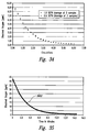
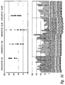
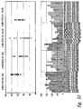
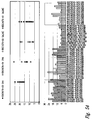
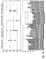
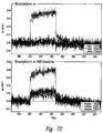
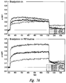
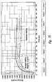
- Table A illustrates various partial pressure measurements taken in a healing wound treated with an oxygen-enriched saline solution and in samples of the gas-enriched oxygen-enriched saline solution of the present invention.
- Experimentation was performed to determine a size of the bubbles of gas diffused within the fluid by the mixing device 100. While experiments were not performed to measure directly the size of the bubbles, experiments were performed that established that the bubble size of the majority of the gas bubbles within the fluid was smaller than 0.1 microns. In other words, the experiments determined a size threshold value below which the sizes of the majority of bubbles fall.
- This size threshold value or size limit was established by passing the output material 102 formed by processing a fluid and a gas in the mixing device 100 through a 0.22 filter and a 0.1 micron filter.
- a volume of the first material 110 in this case, a fluid and a volume of the second material 120, in this case, a gas
- a volume of the output material 102 i.e., a fluid having a gas diffused therein.
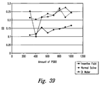
- Sixty milliliters of the output material 102 was drained into a 60 ml syringe.
- the DO level of the fluid within the syringe was then measured using an Orion 862a.
- the Orion 862a is capable of measuring DO levels within a fluid.
- the DO levels measured within the syringe and the DO levels measured within the 50 ml beaker were not changed drastically by passing the output material 102 through the 0.22 micron filter.
- the implication of this experiment is that the bubbles of dissolved gas within the output material 102 are not larger than 0.22 microns otherwise there would be a significantly greater reduction in the DO levels in the output material 102 passed through the 0.22 micron filter.
- a second test was performed in which the 0.1 micron filter was substituted for the 0.22 micron filter.
- saline solution was processed with oxygen in the mixing device 100 and a sample of the output material 102 was collected in an unfiltered state.
- the DO level of the unfiltered sample was 44.7 ppm.
- the output material 102 was filtered using the 0.1 micron filter and two additional samples were collected.
- the DO level of the first sample was 43.4 ppm.
- the DO level of the second sample was 41.4 ppm.
- the filter was removed and a final sample was taken from the unfiltered output material 102.
- the final sample had a DO level of 45.4 ppm.
- the double-layer (interfacial) (DL) appears on the surface of an object when it is placed into a liquid.
- This object for example, might be that of a solid surface (e.g., rotor and stator surfaces), solid particles, gas bubbles, liquid droplets, or porous body.
- bubble surfaces represent a significant portion of the total surface area present within the mixing chamber that may be available for electrokinetic double-layer effects. Therefore, in addition to the surface area and retention time aspects discussed elsewhere herein, the relatively small bubble sizes generated within the mixer 100 compared to prior art devices 10, may also contribute, at least to some extent, to the overall electrokinetic effects and output fluid properties disclosed herein.
- the mixer 100 all of the gas is being introduced via apertures on the rotor (no gas is being introduced through stator apertures. Because the rotor is rotating at a high rate (e.g., 3,400 rpm) generating substantial shear forces at and near the rotor surface, the bubble size of bubbles introduced via, and adjacent to the spinning rotor surface apertures would be expected to be substantially (e.g., 2 to 3-times smaller) smaller than those introduced via and near the stationary stator.
- the average bubble size of the prior art device 10 may, therefore, be substantially larger because at least half of the gas is introduced into the mixing chamber from the stationary stator apertures. Because the surface area of a sphere surface varies with r 2 , any such bubble component of the electrokinetic surface area of the mixing device 100 may be substantially greater than that of the prior art diffusion device 10.
- compositions comprising hydrated (solvated) electrons imparted to the inventive compositions by the inventive processes
- the gas-enriched fluid is generated by the disclosed electromechanical processes in which molecular oxygen is diffused or mixed into the fluid and may operate to stabilize charges (e.g., hydrated (solvated) electrons) imparted to the fluid.
- charges e.g., hydrated (solvated) electrons
- certain embodiments of the present invention relate to a oxygen-enriched fluid (output material) comprising charges (e.g., hydrated (solvated) electrons) that are added to the materials as the first material is mixed with oxygen in the inventive mixer device to provide the combined output material.
- these hydrated (solvated) electrons are stabilized in the inventive solutions as evidenced by the persistence of assayable effects mediated by these hydrated (solvated) electrons.
- Certain embodiments may relate to hydrated (solvated) electrons and/or water-electron structures, clusters, etc., (See, for example, Lee and Lee, Bull. Kor. Chem. Soc. 2003, v. 24, 6; 802-804; 2003 ).
- Horseradish peroxidase (HRP) effects Horseradish peroxidase (HRP) effects. Horseradish peroxidase (HRP) is isolated from horseradish roots ( Amoracia rusticana ) and belongs to the ferroprotoporphyrin group (Heme group) of peroxidases. HRP readily combines with hydrogen peroxide or other hydrogen donors to oxidize the pyrogallol substrate. Additionally, as recognized in the art, HRP facilitates auto-oxidative degradation of indole-3-acetic acid in the absence of hydrogen peroxide (see, e.g., Heme Peroxidases, H.
- the HRP reaction can be measured in enzymatic activity units, in which Specific activity is expressed in terms of pyrogallol units.
- One pyrogallol unit will form 1.0 mg purpurogallin from pyrogallol in 20 sec at pH 6.0 at 20°C. This purpurogallin (20 sec) unit is equivalent to approx. 18 ⁇ M units per min at 25°C.
- Horseradish peroxidase enzyme catalyzes the auto-oxidation of pyrogallol by way of facilitating reaction with the molecular oxygen in a fluid.
- Achjehpour et al., PROTEINS: Struct, Funct, Genet. 53: 656-666 (2003 ) It is also known that oxygen binds the heme pocket of horseradish peroxidase enzyme through a hydrophobic pore region of the enzyme (between Phe68 and Phe142), whose conformation likely determines the accessibility of oxygen to the interior.
- the solvated electrons present in the inventive gas-enriched fluid may act to alter the conformation of the horseradish peroxidase such that greater oxygen accessibility may result.
- the greater accessibility of oxygen to the prosthetic heme pocket of the horseradish peroxidase enzyme may in turn allow for increased HRP reactivity, when compared with prior art oxygenated fluids (pressure-pot, fine-bubbled).
- production of output material using the inventive methods and devices comprises a process involving: an interfacial double layer that provides a charge gradient; movement of the materials relative to surfaces pulling charge (e.g., electrons) away from the surface by virtue of a triboelectric effect, wherein the flow of material produces a flow of solvated electrons.
- the orbital structure of diatomic oxygen creates charge imbalances (e.g., the two unpaired electrons affecting the hydrogen bonding of the water) in the hydrogen bonding arrangement within the fluid material (water), wherein electrons are solvated and stabilized within the imbalances.
- inventive oxygen-enriched fluid of the present application contain no, or less than 0.1 ppm hydrogen peroxide.
- the inventive combination of oxygen-enrichment and solvated electrons imparted by the double-layer effects and configuration of the presently claimed devices may act to alter the conformation and/or heme group accessibility of the horseradish peroxidase.
- the inventive oxygen-enriched output fluid material was tested for the presence of hydrogen peroxide by testing the reactivity with glutathione peroxidase using a standard assay (Sigma). Briefly, glutathione peroxidase enzyme cocktail was constituted in deionized water and the appropriate buffers. Water samples were tested by adding the enzyme cocktail and inverting. Continuous spectrophotometric rate determination was made at A 340 nm, and room temperature (25 degrees Celsius). Samples tested were: 1. deionized water (negative control), 2. inventive oxygen-enriched fluid at low concentration, 3. inventive oxygen-enriched fluid at high concentration, and 4. hydrogen peroxide (positive control). The hydrogen peroxide positive control showed a strong reactivity, while none of the other fluids tested reacted with the glutathione.
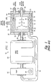
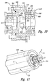
- FIG. 1 provides a partial block diagram, partial cross-sectional view of a prior art device 10 for diffusing or emulsifying one or two gaseous or liquid materials ("infusion materials”) into another gaseous or liquid material ("host material”) reproduced from U.S. Patent No. 6,386,751 , incorporated herein by reference in its entirety.
- the device 10 includes a housing configured to house a stator 30 and a rotor 12.
- the stator 30 encompasses the rotor 12.
- a tubular channel 32 is defined between the rotor 12 and the stator 30.
- the generally cylindrically shaped rotor 12 has a diameter of about 7.500 inches and a length of about 6.000 inches providing a length to diameter ratio of about 0.8.
- the rotor 12 includes a hollow cylinder, generally closed at both ends. A gap exists between each of the first and second ends of the rotor 12 and a portion of the housing 34.
- a rotating shaft 14 driven by a motor 18 is coupled to the second end of the rotor 12.
- the first end of the rotor 12 is coupled to an inlet 16.
- a first infusion material passes through the inlet 16 and into the interior of the rotor 12.
- the first infusion material passes from the interior of the rotor 12 and into the channel 32 through a plurality of openings 22 formed in the rotor 12.
- the stator 30 also has openings 22 formed about its circumference.
- An inlet 36 passes a second infusion material to an area 35 between the stator 30 and the housing 34.
- the second infusion material passes out of the area 35 and into the channel 32 through openings 22.
- An external pump (not shown) is used to pump the host material into a single inlet port 37.
- the host material passes through a single inlet port 37 and into the channel 32 where it encounters the first and second infusion materials, which enter the channel 32 through openings 22.
- the infusion materials may be pressurized at their source to prevent the host material from passing through openings 22.
- the inlet port 37 is configured and positioned such that it is located along only a relatively small portion ( ⁇ about 5%) of the annular inlet channel 32, and is substantially parallel to the axis of rotation of the rotor 12 to impart an axial flow toward a portion of the channel 32 into the host material.
- the host material before entering the tubular channel 32, the host material must travel in tortuous directions other than that of the axial flow (e.g., including in directions substantially orthogonal thereto) and down into and between the gap formed between the first end of the rotor 12 and the housing 34 (i.e., down a portion of the first end of the rotor adjacent to the inlet 16 between the end of the rotor 12 and the housing 34).
- the non-axial and orthogonal flow, and the presence of the host material in the gap between the first end of the rotor 12 and the housing 34 causes undesirable and unnecessary friction.
- the host material must negotiate at least two right angles to enter any aspect of the annual of the annular inlet of the tubular channel 32.
- a single outlet port 40 is formed in the housing 34.
- the combined host material and infusion material(s) exit the channel 32 via the outlet 40.
- the outlet port 40 which is also located along only a limited portion ( ⁇ about 5%) of the annular outlet of tubular channel 32, is substantially parallel to the axis of rotation of the rotor 12 to impart or allow for an axial flow of the combined materials away from the limited portion of the annular outlet of tubular channel 32 into the outlet port 40.
- An external pump 42 is used to pump the exiting fluid through the outlet port 40.
- the inlet port 37 imparts only an axial flow to the host material. Only the rotor 21 imparts a circumferential flow into the host material. Further, the outlet port 40 imparts or provides for only an axial flow into the exiting material. Additionally, the circumferential flow velocity vector is imparted to the material only after it enters the annular inlet 37 of the tubular channel 32, and subsequently the circumferential flow vector must be degraded or eliminated as the material enters the exit port 40. There is, therefore, a need for a progressive circumferential acceleration of the material as it passes in the axial direction through the channel 32, and a circumferential deceleration upon exit of the material from the channel 32.
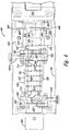
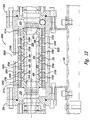
- Figure 2 provides a block diagram illustrating some of the components of a mixing device 100 and the flow of material into, within, and out of the device.
- the mixing device 100 combines two or more input materials to form an output material 102, which may be received therefrom into a storage vessel 104.
- the mixing device 100 agitates the two or more input materials in a novel manner to produce an output material 102 having novel characteristics.
- the output material 102 may include not only a suspension of at least one of the input materials in at least one of the other input materials (e.g., emulsions) but also a novel combination (e.g., electrostatic combinations) of the input materials, a chemical compound resulting from chemical reactions between the input materials, combinations having novel electrostatic characteristics, and combinations thereof.
- the input materials may include a first material 110 provided by a source 112 of the first material, a second material 120 provided by a source 122 of the second material, and optionally a third material 130 provided by a source 132 of the third material.
- the first material 110 may include a liquid, such as water, saline solution, chemical suspensions, polar liquids, non-polar liquids, colloidal suspensions, cell growing media, and the like.
- the first material 110 may include the output material 102 cycled back into the mixing device 100.
- the second material 120 may consist of or include a gas, such as oxygen, nitrogen, carbon dioxide, carbon monoxide, ozone, sulfur gas, nitrous oxide, nitric oxide, argon, helium, bromine, and combinations thereof, and the like.
- the gas is or comprises oxygen.
- the optional third material 130 may include either a liquid or a gas.
- the third material 130 may be or include the output material 102 cycled back into the mixing device 100 (e.g., to one or more of the pumps 210, 220 or 230, and/or into the chamber 310, and/or 330).
- the first material 110, the second material 120, and the optional third material 130 may be pumped into the mixing device 100 by an external pump 210, an external pump 220, and an external pump 230, respectively.
- one or more of the first material 110, the second material 120, and the optional third material 130 may be stored under pressure in the source 112, the source 122, and the source 132, respectively, and may be forced into the mixing device 100 by the pressure.
- the invention is not limited by the method used to transfer the first material 110, the second material 120, and optionally, the third material 130 into the mixing device 100 from the source 112, the source 122, and the source 132, respectively.
- the mixing device 100 includes a first chamber 310 and a second chamber 320 flanking a mixing chamber 330.
- the three chambers 310, 320, and 330 are interconnected and form a continuous volume.
- the first material 110 is transferred into the first chamber 310 and flows therefrom into the mixing chamber 330.
- the first material 110 in the first chamber 310 may be pumped into the first chamber 310 by an internal pump 410.
- the second material 120 is transferred into the mixing chamber 330.
- the third material 130 may be transferred into the mixing chamber 330.
- the materials in the mixing chamber 330 are mixed therein to form the output material 102.
- the output material 102 flows into the second chamber 320 from which the output material 102 exits the mixing device 100.
- the output material 102 in the mixing chamber 330 may be pumped into the second chamber 320 by an internal pump 420.
- the output material 102 in the second chamber 320 may be pumped therefrom into the storage vessel 104 by an external pump 430 (e.g., alone or in combination with the internal pump 410 and/or 420).
- a common drive shaft 500 powers both the internal pump 410 and the internal pump 420.
- the drive shaft 500 passes through the mixing chamber 330 and provides rotational force therein that is used to mix the first material 110, the second material 120, and optionally, the third material 130 together.
- the drive shaft 500 is powered by a motor 510 coupled thereto.
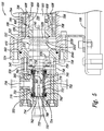
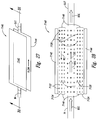
- Figure 3 provides a system 512 for supplying the first material 110 to the mixing device 100 and removing the output material 102 from the mixing device 100.
- the storage vessel 104 of the output material 102 and the source 112 of the first material 110 are combined.
- the external pump 210 is coupled to the combined storage vessel 104 and source 112 by a fluid conduit 514 such as hose, pipe, and the like.
- the external pump 210 pumps the combined first material 110 and output material 102 from the combined storage vessel 104 and source 112 through the fluid conduit 514 and into a fluid conduit 516 connecting the external pump 210 to the mixing device 100.
- the output material 102 exits the mixing device 100 through a fluid conduit 518.
- the fluid conduit 518 is coupled to the combined storage vessel 104 and source 112 and transports the output material 102 exiting the mixing device 100 to the combined storage vessel 104 and source 112.
- the fluid conduit 518 includes a valve 519 that establishes an operating pressure or back pressure within the mixing device 100.
- the mixing device 100 is scalable. Therefore, dimensions provided with respect to various components may be used to construct an embodiment of the device or may be scaled to construct a mixing device of a selected size.
- the mixing device 100 includes a housing 520 that houses each of the first chamber 310, the mixing chamber 330, and the second chamber 320.
- the mixing device 100 includes the drive shaft 500, which rotates during operation of the device. Therefore, the mixing device 100 may vibrate or otherwise move.
- the mixing device 100 may be coupled to a base 106, which may be affixed to a surface such as the floor to maintain the mixing device 100 in a substantially stationary position.
- the housing 520 may be assembled from two or more housing sections.
- the housing 520 may include a central section 522 flanked by a first mechanical seal housing 524 and a second mechanical seal housing 526.
- a bearing housing 530 may be coupled to the first mechanical seal housing 524 opposite the central section 522.
- a bearing housing 532 may be coupled to the second mechanical seal housing 526 opposite the central section 522.
- a housing section 550 may be coupled to the bearing housings 530.
- Each of the bearing housings 530 and 532 may house a bearing assembly 540 (see Figures 5 and 6 ).
- the bearing assembly 540 may include any suitable bearing assembly known in the art including a model number "202SZZST" manufactured by SKF USA Inc, of Kulpsville, Pennsylvania, operating a website at www.skf.com.
- Seals may be provided between adjacent housing sections.
- o-ring 560 (see Figure 5 ) may be disposed between the housing section 550 and the bearing housing 530
- o-ring 562 may be disposed between the first mechanical seal housing 524 and the central section 522
- o-ring 564 (see Figure 6 ) may be disposed between the second mechanical seal housing 526 and the central section 522.
- the mixing chamber 330 is disposed inside the central section 522 of the housing 520 between the first mechanical seal housing 524 and the second mechanical seal housing 526.
- the mixing chamber 330 is formed between two components of the mixing device 100, a rotor 600 and a stator 700.
- the rotor 600 may have a sidewall 604 with an inside surface 605 defining a generally hollow inside portion 610 and an outside surface 606.
- the sidewall 604 may be about 0.20 inches to about 0.75 inches thick. In some embodiments of the disclosure, the sidewall 604 is about 0.25 inches thick.
- the mixing device 100 may be scaled to suit a particular application, embodiments of the disclosure of the device having a sidewall 604 that is thicker or thinner than the values provided are within the scope of the present teachings.
- the sidewall 604 includes a first end portion 612 and a second end portion 614 and a plurality of through-holes 608 formed between the first end portion 612 and the second end portion 614.
- the outside surface 606 of the sidewall 604 may include other features such as apertures, projections, textures, and the like.
- the first end portion 612 has a relieved portion 616 configured to receive a collar 618 and the second end portion 614 has a relieved portion 620 configured to receive a collar 622.
- the rotor 600 is disposed inside the stator 700.
- the stator 700 has a sidewall 704 with an inside surface 705 defining a generally hollow inside portion 710 into which the rotor 600 is disposed.
- the sidewall 704 may be about 0.1 inches to about 0.3 inches thick. In some embodiments of the disclosure, the sidewall 604 is about 1.5 inches thick.
- the stator 700 may be non-rotatably coupled to the housing 520 in a substantially stationary position. Alternatively, the stator 700 may integrally formed with the housing 520.
- the sidewall 704 has a first end portion 712 and a second end portion 714.
- the plurality of apertures 708 are formed in the sidewall 704 of the stator 700 between the first end portion 712 and the second end portion 714.
- the inside surface 705 of the sidewall 704 may include other features such as through-holes, projections, textures, and the like.
- the rotor 600 rotates with respect to the stationary stator 700 about an axis of rotation "a" in a direction indicated by arrow "C3" in Figure 9 .
- Each of the rotor 600 and the stator 700 may be generally cylindrical in shape and have a longitudinal axis.
- the rotor 600 has an outer diameter "D1" and the stator 700 may have an inner diameter "D2".
- the diameter "D1” may range, for example, from about 0.5 inches to about 24 inches. In some embodiments of the disclosure, the diameter "D1" is about 3.04 inches. In some embodiments of the disclosure, the diameter "D1" is about 1.7 inches.
- the diameter "D2" which is larger than the diameter "D1,” may range from about 0.56 inches to about 24.25 inches.
- the diameter "D2" is about 4 inches. Therefore, the mixing chamber 330 may have a ring-shaped cross-sectional shape that is about 0.02 inches to about 0.125 inches thick (i.e., the difference between the diameter "D2" and the diameter "D1"). In particular embodiments of the disclosure, the mixing chamber 330 is about 0.025 inches thick.
- the channel 32 between the rotor 12 and the stator 34 of prior art device 10 has a ring-shaped cross-sectional shape that is about 0.09 inches thick. Therefore, in particular embodiments of the disclosure, the thickness of the mixing chamber 330 is less than about one third of the channel 32 of the prior art device 10.
- the longitudinal axis of the rotor 600 may be aligned with its axis of rotation "a.”
- the longitudinal axis of the rotor 600 may be aligned with the longitudinal axis of the stator 700.
- the rotor 600 may have a length of about 3 inches to about 6 inches along the axis of rotation "a.” In some embodiments of the disclosure, the rotor 600 may have a length of about 5 inches along the axis of rotation "a.”
- the stator 700 may have a length of about 3 inches to about 6 inches along the axis of rotation "a.” In some embodiments of the disclosure, the stator 700 may have a length of about 5 inches along the axis of rotation "a.”
- the rotor 600 and the stator 700 have been depicted as having a generally cylindrical shape, those of ordinary skill in the art appreciate that alternate shapes may be used.
- the rotor 600 and the stator 700 may be conically, spherically, arbitrarily shaped, and the like.
- the rotor 600 and the stator 700 need not be identically shaped.
- the rotor 600 may be cylindrically shaped and the stator 700 rectangular shaped or vice versa.
- the apertures 708 of the stator 700 and the through-holes 608 depicted in Figures 4-7 are generally cylindrically shaped.
- the diameter of the through-holes 608 may range from about 0.1 inches to about 0.625 inches.
- the diameter of the apertures 708 may range from about 0.1 inches to about 0.625 inches.
- One or more of apertures 708 of the stator 700 may have a diameter that differs from the diameters of the other apertures 708.
- the apertures 708 may increase in diameter from the first end portion 712 of the stator 700 to the second end portion 714 of the stator 700, the apertures 708 may decrease in diameter from the first end portion 712 of the stator 700 to the second end portion 714 of the stator 700, or the diameters of the apertures 708 may vary in another manner along the stator 700.
- One or more of through-holes 608 of the rotor 600 may have a diameter that differs from the diameters of the other through-holes 608.
- the through-holes 608 may increase in diameter from the first end portion 612 of the rotor 600 to the second end portion 614 of the rotor 600, the through-holes 608 may decrease in diameter from the first end portion 612 of the rotor 600 to the second end portion 614 of the rotor 600, or the diameters of the through-holes 608 may vary in another manner along the rotor 600.
- the apertures 708 and the through-holes 608 may have shapes other than generally cylindrical and such embodiments are within the scope of the present invention.
- the through-holes 608 may include a narrower portion, an arcuate portion, a tapered portion, and the like.
- each of the through-holes 608 includes an outer portion 608A, a narrow portion 608B, and a tapered portion 608C providing a transition between the outer portion 608A and the narrow portion 608B.
- the apertures 708 may include a narrower portion, an arcuate portion, a tapered portion, and the like.
- Figure 8 provides a non-limiting example of a suitable arrangement of the apertures 708 of the stator 700 and the through-holes 608 of the rotor 600.
- the apertures 708 of the stator 700 may be arranged in substantially parallel lateral rows "SLAT-1" through “SLAT-6" substantially orthogonal to the axis of rotation "a.”
- the apertures 708 of the stator 700 may also be arranged in substantially parallel longitudinal rows "SLONG-1" through “SLONG-7” substantially parallel with the axis of rotation "a.”
- the apertures 708 of the stator 700 may be arranged in a grid-like pattern of orthogonal rows (i.e., the lateral rows are orthogonal to the longitudinal rows) having the longitudinal rows "SLONG-1" through “SLONG-7” substantially parallel with the axis of rotation "a.”
- the through-holes 608 of the rotor 600 may be arranged in substantially parallel lateral rows "RLAT-1" through “RLAT-6" substantially orthogonal to the axis of rotation "a.”
- the through-holes 608 of the rotor 600 may also be arranged in substantially parallel rows “RLONG-1” through “RLONG-7” that extend longitudinally along a helically path.
- the through-holes 608 of the rotor 600 may also be arranged in substantially parallel rows "RLONG-1” through “RLONG-7” that extend longitudinally at an angle other than parallel with the axis of rotation "a.”
- the apertures 708 of the stator 700 and the through-holes 608 of the rotor 600 may be configured so that when the rotor 600 is disposed inside the stator 700 the lateral rows "SLAT-1" to "SLAT-6" at least partially align with the lateral rows “RLAT-1” to “RLAT-6,” respectively. In this manner, as the rotor 600 rotates inside the stator 700, the through-holes 608 pass by the apertures 708.
- the through-holes 608 in each of the lateral rows “RLAT-1" to “RLAT-6” may be spaced apart laterally such that all of the through-holes 608 in the lateral row align, at least partially, with the apertures 708 in a corresponding one of the lateral rows "SLAT-1" to "SLAT-6" of the stator 700 at the same time.
- the longitudinally extending rows “RLONG-1" through “RLONG-6” may be configured such that the through-holes 608 in the first lateral row "RLAT-1" in each of the longitudinally extending rows passes completely by the apertures 708 of the corresponding lateral row "SLAT-1" before the through-holes 608 in the last lateral row “RLAT-6” begin to partially align with the apertures 708 of the corresponding last lateral row "SLAT-6" of the stator 700.
- the number of apertures 708 in each of the lateral rows "SLAT-1" to “SLAT-6" on the stator 700 may differ by a predetermined number (e.g., one, two, and the like) the number of through-holes 608 in each of the corresponding lateral rows “RLAT-1” to "RLAT-6" on the rotor 600.
- a predetermined number e.g., one, two, and the like
- the lateral row “SLAT-1” may have twenty apertures 708 evenly spaced around the circumference of stator 700.
- the mixing chamber 330 has an open first end portion 332 and an open second end portion 334.
- the through-holes 608 formed in the sidewall 604 of the rotor 600 connect the inside portion 610 of the rotor 600 with the mixing chamber 330.
- the rotor 600 is rotated inside the stator 700 by the drive shaft 500 aligned with the axis of rotation "a" of the rotor 600.
- the drive shaft 500 may be coupled to the first end portion 612 and the second end portion 614 of the rotor 600 and extend through its hollow inside portion 610. In other words, a portion 720 of the drive shaft 500 is disposed in the hollow inside portion 610 of the rotor 600.
- the collar 618 is configured to receive a portion 721 of the drive shaft 500 disposed in the hollow inside portion 610 and the collar 622 is configured to receive a portion 722 of the drive shaft 500 disposed in the hollow inside portion 610.
- the portion 721 has an outer diameter "D3” that may range from about 0.5 inches to about 2.5 inches. In some embodiments, the diameter "D3" is about 0.625 inches.
- the portion 722 has an outer diameter "D4" that may be substantially similar to the diameter "D3,” although, this is not required. The diameter "D4" may range from about 0.375 inches to about 2.5 inches.
- the rotor 600 may be non-rotationally affixed to the portion 721 and the portion 722 of the drive shaft 500 by the collar 618 and the collar 622, respectively.
- each of the collars 618 and 622 may be installed inside relieved portions 616 and 620, respectively.
- the combined rotor 600 and collars 618 and 622 may be heated to expand them.
- the drive shaft 500 is inserted through the collars 618 and 622 and the assembly is allowed to the cool. As the collars 618 and 622 shrink during cooling, they tighten around the portions 722A and 722B of the drive shaft 500, respectively, gripping it sufficiently tightly to prevent the drive shaft 500 from rotating relative to the rotor 600.
- the collar 618 which does not rotate with respect to either the portion 721 or the relieved portion 616, translates the rotation of the drive shaft 500 to the first end portion 612 the rotor 600.
- the collar 622 which does not rotate with respect to either the portion 722 or the relieved portion 620, translates the rotation of the drive shaft 500 to the second end portion 614 of the rotor 600.
- the drive shaft 500 and the rotor 600 rotate together as a single unit.
- the drive shaft 500 may have a first end portion 724 (see Figure 5 ) and a second end portion 726 (see Figure 6 ).
- the first end portion 724 may have a diameter "D5" of about 0.5 inches to about 1.75 inches. In particular embodiments, the diameter "D5" may be about 1.25 inches.
- the second end portion 726 may have a diameter "D6" that may be substantially similar to diameter "D5.”
- the second material 120 may be transported into the mixing chamber 330 through one of the first end portion 724 and the second end portion 726 of the rotating drive shaft 500.
- the other of the first end portion 724 and the second end portion 726 of the drive shaft 500 may be coupled to the motor 510.
- the second material 120 is transported into the mixing chamber 330 through the first end portion 724 and the second end portion 726 of the drive shaft 500 is coupled to the motor 510.
- the drive shaft 500 may have a channel 728 formed therein that extends from first end portion 724 into the portion 720 disposed in the inside portion 610 of the rotor 600.
- the channel 728 has an opening 730 formed in the first end portion 724.
- a valve 732 may be disposed inside a portion of the channel 728 located in the first end portion 724 of the drive shaft 500.
- the valve 732 may restrict or otherwise control the backward flow of the second material 120 from inside the hollow inside portion 610 through the channel 728 and/or the forward flow of the second material 120 into the channel 728.
- the valve 732 may include any valve known in the art including a check valve.
- a suitable check valve includes a part number "CKFA1876205A,” free flow forward check valve, manufactured by The Lee Company USA having an office in Bothell, WA and operating a website at www.theleeco.com.
- the drive shaft 500 may include an aperture 740 located in the inside portion 610 of the rotor 600 that connects the channel 728 with the inside portion 610 of the rotor 600. While only a single aperture 740 is illustrated in Figure 5 , it is apparent to those of ordinary skill in the art that multiple apertures may be used to connect the channel 728 with the inside portion 610 of the rotor 600.
- the external pump 220 may pump the second material 120 into the mixing device 100.
- the pump 220 may include any suitable pump known in the art.
- the pump 220 may include any suitable pump known in the art including a diaphragm pump, a chemical pump, a peristaltic pump, a gravity fed pump, a piston pump, a gear pump, a combination of any of the aforementioned pumps, and the like.
- the second material 120 is a gas
- the gas may be pressurized and forced into the opening 730 formed in the first end portion 724 of the drive shaft 500 by releasing the gas from the source 122.
- the pump 220 or the source 122 is coupled to the channel 728 by the valve 732.
- the second material 120 transported inside the channel 728 exits the channel 728 into the inside portion 610 of the rotor 600 through the aperture 740.
- the second material 120 subsequently exits the inside portion 610 of the rotor 600 through the through-holes 608 formed in the sidewall 608 of the rotor 600.
- the mixing device 100 may include a seal assembly 750 coupled to the first end portion 724 of the drive shaft 500.
- the seal assembly 750 is maintained within a chamber 752 defined in the housing 520.
- the chamber 752 has a first end portion 754 spaced across the chamber from a second end portion 756.
- the chamber 752 also includes an input port 758 and an output port 759 that provide access into the chamber 752.
- the chamber 752 may be defined by housing section 550 and the bearing housing 530.
- the first end portion 754 may be formed in the housing section 550 and the second end portion 756 may be adjacent to the bearing housing 530.
- the input port 758 may be formed in the bearing housing 530 and the output port 759 may be formed in the housing section 550.
- the seal assembly 750 includes a first stationary seal 760 installed in the first end portion 754 of the chamber 752 in the housing section 550 and the bearing housing 530.
- the first stationary seal 760 extends around a portion 762 of the first end portion 724 of the drive shaft 500.
- the seal assembly 750 also includes a second stationary seal 766 installed in the second end portion 756 of the chamber 752 in the bearing housing 530.
- the second stationary seal 766 extends around a portion 768 of the first end portion 724 of the drive shaft 500.
- the seal assembly 750 includes a rotating assembly 770 that is non-rotatably coupled to the first end portion 724 of the drive shaft 500 between the portion 762 and the portion 768.
- the rotating assembly 770 rotates therewith as a unit.
- the rotating assembly 770 includes a first seal 772 opposite a second seal 774.
- a biasing member 776 e.g., a spring
- the biasing member 776 biases the first seal 772 against the first stationary seal 760 and biases the second seal 774 against the second stationary seal 766.
- a cooling lubricant is supplied to the chamber 752 and around rotating assembly 770.
- the lubricant enters the chamber 752 through the input port 758 and exits the chamber 752 through output port 759.
- the lubricant may lubricate the bearing assembly 540 housed by the bearing housing 530.
- a chamber 570 may be disposed between the bearing housing 530 and the mechanical seal housing 524.
- the bearing housing 530 may also include a second input port 759 connected to the chamber 570 into which lubricant may be pumped. Lubricant pumped into the chamber 570 may lubricate the bearing assembly 540.
- the seal assembly 750 may significantly, if not greatly, reduce frictional forces within this portion of the device caused by the rotation of the rotor 600 and may increase the active life of the seals 770.
- the seals may include surfaces constructed using silicon carbide.
- the rotor 600 rotates about the axis of rotation "a" in the direction indicated by arrow "C1," the rotor expels the second material 120 into the mixing chamber 330.
- the expelled bubbles, droplets, particles, and the like of the second material 120 exit the rotor 600 and are imparted with a circumferential velocity (in a direction indicated by arrow "C3") by the rotor 600.
- the second material 120 may forced from the mixing chamber 330 by the pump 220 (see Figure 2 ), the centrifugal force of the rotating rotor 600, buoyancy of the second material 120 relative to the first material 110, and a combination thereof.
- the second end portion 726 of the drive shaft 500 may be coupled to a rotating spindle 780 of a motor 510 by a coupler 900.
- the spindle 780 may have a generally circular cross-sectional shape with a diameter "D7" of about 0.25 inches to about 2.5 inches. In particular embodiments, the diameter "D7" may be about 0.25 inches to about 1.5 inches. While in the embodiment depicted in Figure 6 , the diameter "D5" of the first end portion 724 of the drive shaft 500 is substantially equal to the diameter "D7" and the spindle 780, embodiments in which one of the diameter "D5" and the diameter "D7" is larger than the other are within the scope of the present invention.
- a drive guard 910 covers the coupler 900.
- the drive guard 910 may be generally U-shaped having a curved portion 914 flanked by a pair of substantially linear portions 915 and 916.
- the distal end of each of the substantially linear portions 915 and 916 of the drive guard 910 may have a flange 918 and 919, respectively.
- the drive guard 910 may be fastened by each of its flanges 918 and 919 to the base 106.
- the motor 510 may be supported on the base 106 by a support member 920.
- the support member 920 may be coupled to the motor 510 near the spindle 780.
- the support member 920 includes a through-hole through which the spindle 780 passes.
- the support member 920 may be coupled to the motor 510 using any method known in the art, including bolting the support member 920 to the motor 510 with one or more bolts 940.
- the coupler 900 may include any coupler suitable for transmitting a sufficient amount of torque from the spindle 780 to the drive shaft 500 to rotate the rotor 600 inside to the stator 700.
- the coupler 900 is a bellows coupler.
- a bellows coupler may be beneficial if the spindle 780 and the drive shaft 500 are misaligned. Further, the bellows coupler may help absorb axial forces exerted on the drive shaft 500 that would otherwise be translated to the spindle 780.
- a suitable bellows coupler includes a model "BC32-8-8-A,” manufactured by Ruland Manufacturing Company, Inc. of Marlborough, MA, which operates a website at www.ruland.com.
- the motor 510 may rotate the rotor 600 at about 0.1 revolutions per minute ("rpm") to about 7200 rpm.
- the motor 510 may include any motor suitable for rotating the rotor 600 inside to the stator 700 in accordance with the present teachings.
- a suitable motor may include a one-half horsepower electric motor, operating at 230/460 volts and 3450 per minute ("rpm").
- a suitable motor includes a model "C4T34NC4C” manufactured by LEESON Electric Corporation of Grafton, WI, which operates a website at www.leeson.com.
- the first chamber 320 is disposed inside the central section 522 of the housing 520 between the first mechanical seal housing 524 and the first end portions 612 and 712 of the rotor 600 and the stator 700, respectively.
- the first chamber 310 may be annular and have a substantially circular cross-sectional shape.
- the first chamber 310 and the mixing chamber 330 form a continuous volume.
- a portion 1020 of the drive shaft 500 extends through the first chamber 310.
- the first chamber 310 has an input port 1010 through which the first material 110 enters the mixing device 100.
- the first material 110 may be pumped inside the first chamber 310 by the external pump 210 (see Figure 2 ).
- the external pump 210 may include any pump known in the art for pumping the first material 110 at a sufficient rate to supply the first chamber 310.
- the input port 1010 is oriented substantially orthogonally to the axis of rotation "a.” Therefore, the first material 110 enters the first chamber 310 with a velocity tangential to the portion 1020 of the drive shaft 500 extending through the first chamber 310.
- the tangential direction of the flow of the first material 110 entering the first chamber 310 is identified by arrow "T1.”
- the input port 1010 may be offset from the axis of rotation "a.”
- the direction of the rotation of the drive shaft 500 (identified by arrow "C1" in Figure 9 ), has a tangential component.
- the input port 1010 is positioned so that the first material 110 enters the first chamber 310 traveling in substantially the same direction as the tangential component of the direction of rotation of the drive shaft 500.
- the first material 110 enters the first chamber 310 and is deflected by the inside of the first chamber 310 about the portion 1020 of the drive shaft 500.
- the inside of the first chamber 310 may deflect the first material 110 in a substantially circular path (identified by arrow "C2" in Figure 9 ) about the portion 1020 of the drive shaft 500.
- the tangential velocity of the first material 110 may cause it to travel about the axis of rotation "a" at a circumferential velocity, determined at least in part by the tangential velocity.
- the first material 110 may be pumped from the first chamber 310 into the mixing chamber 330 by the pump 410 residing inside the first chamber 310.
- the external pump 210 may be configured to pump the first material 110 into the first chamber 310 at a rate at least as high as a rate at which the pump 410 pumps the first material 110 from the first chamber 310.
- the first chamber 310 is in communication with the open first end portion 332 of the mixing chamber 330 and the first material 110 inside the first chamber 310 may flow freely into the open first end portion 332 of the mixing chamber 330. In this manner, the first material 110 does not negotiate any corners or bends between the mixing chamber 330 and the first chamber 310.
- the first chamber 310 is in communication with the entire open first end portion 332 of the mixing chamber 330.
- the first chamber 310 may be filled completely with the first material 110.
- the pump 410 is powered by the portion 1020 of the drive shaft 500 extending through the first chamber 310.
- the pump 410 may include any pump known in the art having a rotating pump member 2022 housed inside a chamber (i.e., the first chamber 310) defined by a stationary housing (i.e., the housing 520).
- suitable pumps include rotary positive displacement pumps such as progressive cavity pumps, single screw pumps (e.g., Archimedes screw pump), and the like.
- the pump 410 depicted in Figures 7 and 9 is generally referred to as a single screw pump.
- the pump member 2022 includes a collar portion 2030 disposed around the portion 1020 of the drive shaft 500.
- the collar portion 2030 rotates with the portion 1020 of the drive shaft 500 as a unit.
- the collar portion 2030 includes one or more fluid displacement members 2040.
- the collar portion 2030 includes a single fluid displacement member 2040 having a helical shape that circumscribes the collar portion 2030 along a helical path.
- the pump 410 imparts an axial flow (identified by arrow "A1" and arrow "A2") in the first material 110 inside the first chamber 310 toward the open first end portion 332 of the mixing chamber 330.
- the axial flow of the first material 110 imparted by the pump 410 has a pressure that may exceed the pressure obtainable by the external pump of the prior art device 10 (see Figure 1 ).
- the pump 410 may also be configured to impart a circumferential flow (identified by arrow "C2") in the first material 110 as it travels toward the open first end portion 332 of the mixing chamber 330.
- the circumferential flow imparted in the first material 110 before it enters the mixing chamber 330 causes the first material 110 to enter the mixing chamber 330 already traveling in the desired direction at an initial circumferential velocity.
- the first material 110 entered the channel 32 of the prior art device 10 without a circumferential velocity. Therefore, the rotor 12 of the prior art device 10 alone had to impart a circumferential flow into the first material 110.
- the first material 110 is moving axially, in the prior art device 10, the first material 110 traversed at least a portion of the channel 32 formed between the rotor 12 and the stator 30 at a slower circumferential velocity than the first material 110 traverse the mixing chamber 330 of the mixing device 100.
- the first material 110 may complete more revolutions around the rotational axis "a" before traversing the axial length of the mixing chamber 330, than it would complete before traversing the axial length of the channel 32.
- the additional revolutions expose the first material 110 (and combined first material 110 and second material 120) to a substantially larger portion of the effective inside surface 706 (see Figure 7 ) of the stator 700.
- the circumferential velocity imparted by the external pump 210 combined with the input port 1010 being oriented according to the present teachings may alone sufficiently increase the revolutions of the first material 110 (and combined first material 110 and second material 120) about the rotational axis "a.” Further, in some embodiments of the disclosure, the circumferential velocity imparted by the pump 210 and the circumferential velocity imparted by the pump 410 combine to achieve a sufficient number of revolutions of the first material 110 (and combined first material 110 and second material 120) about the rotational axis "a.” As is appreciated by those of ordinary skill in the art, other structural elements such as the cross-sectional shape of the first chamber 310 may contribute to the circumferential velocity imparted by the pump 210, the pump 410, and a combination thereof.
- the pump 410 may include one or more vanes 2042 configured to impart a circumferential flow in the first material 110 as it travels toward the open first end portion 332 of the mixing chamber 330.
- the second chamber 320 is disposed inside the central section 522 of the housing 520 between the second mechanical seal housing 526 and the second end portions 614 and 714 of the rotor 600 and the stator 700, respectively.
- the second chamber 320 may be substantially similar to the first chamber 310. However, instead of the input port 1010, the second chamber 320 may include an output port 3010. A portion 3020 of the drive shaft 500 extends through the second chamber 320.
- the second chamber 320 and the mixing chamber 330 form a continuous volume. Further, the first chamber 310, the mixing chamber 330, and the second chamber 320 form a continuous volume.
- the first material 110 flows through the mixing device 100 from the first chamber 310 to the mixing chamber 330 and finally to the second chamber 320. While in the mixing chamber 330, the first material 110 is mixed with the second material 120 to form the output material 102.
- the output material 102 exits the mixing device 100 through the output port 3010.
- the output material 102 may be returned to the input port 1010 and mixed with an additional quantity of the second material 120, the third material 130, or a combination thereof.
- the output port 3010 is oriented substantially orthogonally to the axis of rotation "a" and may be located opposite the input port 1010 formed in the first chamber 310.
- the output material 102 enters the second chamber 320 from the mixing chamber 330 having a circumferential velocity (in the direction indicated by arrow "C3" in Figure 9 ) imparted thereto by the rotor 600.
- the circumferential velocity is tangential to the portion 3020 of the drive shaft 500 extending through the second chamber 320.
- the output port 3010 may be offset from the axis of rotation "a."
- the output port 3010 is positioned so that the output material 102, which enters the second chamber 320 traveling in substantially the same direction in which the drive shaft 500 is rotating (identified in Figure 9 by arrow "C1 "), is traveling toward the output port 3010.
- the output material 102 enters the second chamber 320 and is deflected by the inside of the second chamber 320 about the portion 3020 of the drive shaft 500.
- the inside of the second chamber 320 may deflect the output material 102 in a substantially circular path about the portion 3020 of the drive shaft 500.
- the output material 102 may be pumped from inside the second chamber 320 by the external pump 430.
- the external pump 430 may include any pump known in the art for pumping the output material 102 at a sufficient rate to avoid limiting throughput of the mixing device 100.
- the external pump 430 may introduce a tangential velocity (in a direction indicated by arrow "T2" in Figures 4 and 11 ) to at least a portion of the output material 102 as the external pump 430 pumps the output material 102 from the second chamber 320.
- the tangential velocity of the portion of the output material 102 may cause it to travel about the axis of rotation "a" at a circumferential velocity, determined in part by the tangential velocity.
- the pump 420 residing inside the second chamber 320 may pump the output material 102 from the second chamber 320 into the output port 3010 and/or from the mixing chamber 330 into the second chamber 320.
- the external pump 430 may be configured to pump the output material 102 from the second chamber 320 at a rate at least as high as a rate at which the pump 420 pumps the output material 102 into the output port 3010.
- the second chamber 320 is in communication with the open second end portion 334 of the mixing chamber 330 and the output material 102 inside the mixing chamber 330 may flow freely from the open second end portion 334 into the second chamber 320. In this manner, the output material 102 does not negotiate any corners or bends between the mixing chamber 330 and the second chamber 320.
- the second chamber 320 is in communication with the entire open second end portion 334 of the mixing chamber 330.
- the second chamber 320 may be filled completely with the output material 102.
- the pump 420 is powered by the portion 3020 of the drive shaft 500 extending through the second chamber 320.
- the pump 420 may be substantially identical to the pump 410. Any pump described above as suitable for use as the pump 410 may be used for the pump 420. While the pump 410 pumps the first material 110 into the mixing chamber 330, the pump 420 pumps the output material 102 from the mixing chamber 330. Therefore, both the pump 410 and the pump 420 may be oriented to pump in the same direction.
- the first material 110 may differ from the output material 102.
- one of the first material 110 and the output material 102 may be more viscous than the other. Therefore, the pump 410 may differ from the pump 420.
- the pump 410 may be configured to accommodate the properties of the first material 110 and the pump 420 may be configured to accommodate the properties of the output material 102.
- the pump 420 depicted in Figures 6 and 7 is generally referred to as a single screw pump.
- the pump member 4022 includes a collar portion 4030 disposed around the portion 3020 of the drive shaft 500.
- the collar portion 4030 rotates with the portion 3020 of the drive shaft 500 as a unit.
- the collar portion 4030 includes one or more fluid displacement members 4040.
- the collar portion 4030 includes a single fluid displacement member 4040 having a helical shape that circumscribes the collar portion 4030 along a helical path.
- the pump 420 imparts an axial flow (identified by arrow "A3" and arrow "A4") in the output material 102 inside the second chamber 320 away from the open second end portion 334 of the mixing chamber 330.
- the pump 420 may be configured to impart a circumferential flow (identified by arrow "C4") in the output material 102 as it travels away from the open second end portion 334 of the mixing chamber 330.
- the circumferential flow imparted in the output material 102 may help reduce an amount of work required by the rotor 600.
- the circumferential flow also directs the output material 102 toward the output port 3010.
- the pump 420 may have substantially the same configuration of the pump 410 depicted in Figure 10 .
- the one or more vanes 2042 are configured to impart a circumferential flow in the output material 102 as it travels away from the open second end portion 334 of the mixing chamber 330.
- various parameters of the mixing device 100 may be modified to obtain different mixing characteristics.
- Exemplary parameters that may be modified include the size of the through-holes 608, the shape of the through-holes 608, the arrangement of the through-holes 608, the number of through-holes 608, the size of the apertures 708, the shape of the apertures 708, the arrangement of the apertures 708, the number of apertures 708, the shape of the rotor 600, the shape of the stator 700, the width of the mixing chamber 330, the length of the mixing chamber 330, rotational speed of the drive shaft 500, the axial velocity imparted by the internal pump 410, the circumferential velocity imparted by the internal pump 410, the axial velocity imparted by the internal pump 420, the circumferential velocity imparted by the internal pump 420, the configuration of disturbances (e.g., texture, projections, recesses, apertures, and the like) formed on the outside surface 606 of the rotor 600, the configuration of disturbances (e.g., texture, projections
- a mixing device 5000 is depicted.
- the mixing device 5000 is an alternate embodiment of the disclosure of the mixing device 100. Identical reference numerals have been used herein to identify components of the mixing device 5000 that are substantially similar corresponding components of the mixing device 100. Only components of the mixing device 5000 that differ from the components of the mixing device 100 will be described.
- the mixing device 5000 includes a housing 5500 for housing the rotor 600 and the stator 5700.
- the stator 5700 may be non-rotatably couple by its first end portion 5712 and its second end portion 5714 to the housing 5500.
- a chamber 5800 is defined between the housing 5500 and a portion 5820 of the stator 5700 flanked by the first end portion 5712 and the second end portion 5714.
- the housing 5500 includes an input port 5830 which provides access into the chamber 5800.
- the input port 5830 may be oriented substantially orthogonally to the axis of rotation "a.” however, this is not a requirement.
- the stator 5700 includes a plurality of through-holes 5708 that connect the chamber 5800 and the mixing chamber 330 (defined between the rotor 600 and the stator 5700).
- An external pump 230 may be used to pump the third material 130 (which may be identical to the second material 120) into the chamber 5800 via the input port 5830.
- the third material 130 pumped into the chamber 5800 may enter the mixing chamber 330 via the through-holes 5708 formed in the stator 5700.
- the third material 130 may force from the channel 5800 by the pump 230, buoyancy of the third material 130 relative to the first material 110, and a combination thereof.
- the third material 130 may enter the mixing chamber 330 and bubbles, droplets, particles, and the like, which are imparted with a circumferential velocity by the rotor 600.
- FIG. 13 depicts the central section 5900 having in its interior the stator 700 (see Figure 7 ). Identical reference numerals have been used herein to identify components associated with the central section 5900 that are substantially similar corresponding components of the mixing device 100. Only components of the central section 5900 that differ from the components of the central section 522 will be described.
- the central section 5900 and the stator 700 are both constructed from a conductive material such as a metal (e.g., stainless steel).
- the input port 1010 and the output port 3010 are both constructed from a nonconductive material such as plastic (e.g., PET, Teflon, nylon, PVC, polycarbonate, ABS, Delrin, polysulfone, etc.).
- An electrical contact 5910 is coupled to the central section 5900 and configured to deliver a charge to thereto.
- the central section 5900 conducts an electrical charge applied to the electrical contact 5910 to the stator 700.
- the central section 5900 may be constructed from a nonconductive material.
- the electrical contact 5910 may pass through the central section 5900 and coupled to the stator 700. The electric charge applied by the electrical contact 5910 to the stator 700 may help facilitate redox or other chemical reactions inside the mixing chamber 330.
- insulation may be disposed around the central section 5900 to electrically isolate it from the environment. Further, insulation may be used between the central section 5900 and the first and second mechanical seals 524 and 526 that flank it to isolate it electrically from the other components of the mixing device.
- the bearing housing 5920 is disposed circumferentially around the portion 726 of the drive shaft 500.
- An electrical contact 5922 is coupled to the bearing housing 5920.
- a rotating brush contact 5924 provides an electrical connection between the drive shaft 500 and the electrical contact 5922.
- the drive shaft 500 and the rotor 600 are both constructed from a conductive material such as a metal (e.g., stainless steel).
- the bearing housing 5920 may be constructed from either a conductive or a nonconductive material.
- the alternate embodiment of the disclosure of the mixing device 100 constructed using the central section 5900 depicted in Figure 13 and the bearing housing 5920 depicted in Figure 14 may be operated in at least two ways.
- the electrical contacts 5910 and 5922 may be configured not to provide an electrical charge to the stator 700 and the rotor 600, respectively. In other words, neither of the electrical contacts 5910 and 5922 are connected to a current source, and voltage source, and the like.
- the electrical contacts 5910 and 5922 may be configured to provide an electrical charge to the stator 700 and the rotor 600, respectively.
- the electrical contacts 5910 and 5922 may be coupled to ta DC voltage source (not shown) supplying a steady or constant voltage across the electrical contacts 5910 and 5922.
- the negative terminal of the DC voltage source may be coupled to either of the electrical contacts 5910 and 5922 and the positive terminal of the DC voltage source may be coupled to the other of the electrical contacts 5910 and 5922.
- the voltage supplied across the electrical contacts 5910 and 5922 may range from about 0.0001 volts to about 1000 volts. In particular embodiments, the voltage may range from about 1.8 volts to about 2.7 volts.
- a pulsed DC voltage having a duty cycle of between about 1 % to about 99% may be used.
- the first material 110 entered the channel 32 between the rotor 12 and the stator 30 via a single limited input port 37 located along only a portion of the open second end of the channel 32.
- the output material 102 exited the channel 32 via a single limited output port 40 located along only a portion of the open first end of the channel 32.
- This arrangement caused undesirable and unnecessary friction.
- the single limited inlet port 37 and the single limited outlet port 40 With the chambers 310 and 320, respectively, friction has been reduced.
- the first material 110 does not negotiate a corner before entering the mixing chamber 330 and the output material 102 does not negotiate a corner before exiting the mixing chamber 330.
- the chambers 310 and 320 provide for circumferential velocity of the material prior to entering, and after exiting the channel 32.
- pressure drop across the mixing device 100 has been substantially reduced.
- the pressure drop between the input port 1010 and the output port 3010 is only approximately 12 psi when the mixing device 100 is configured to produce about 60 gallons of the output material 102 per minute.
- This is an improvement over the prior art device 10 depicted in Figure 1 , which when producing about 60 gallons of output material per minute was at least 26 psi.
- the pressure drop across the mixing device 100 is less than half that experienced by the prior art device 10.
- pumps 410 and 420 which are powered by the drive shaft 500, provides a configuration that is substantially more efficient in mixing materials and that requires less energy than the external pumps used in the prior art.
- the input materials may include the first material 110 (e.g., a fluid) and the second material 120 (e.g., a gas).
- the first material 110 and the second material 120 are mixed inside the mixing chamber 330 formed between the rotor 600 and the stator 700. Rotation of the rotor 600 inside the stator 700 agitates the first material 110 and the second material 120 inside the mixing chamber 330.
- the through-holes 608 formed in the rotor 600 and/or the apertures 708 formed in the stator 700 impart turbulence in the flow of the first material 110 and the second material 120 inside the mixing chamber 330.
- the efficiency and persistence of the diffusion of the second material 120 into the first material 110 is believed to be caused in part by micro-cavitation, which is described in connection with Figures 15-17 .
- micro-cavitation which is described in connection with Figures 15-17 .
- a rather laminar flow is established with a thin boundary layer that is stationary or moving very slowly because of the surface tension between the moving fluid and the stationary surface.
- the through-holes 608 and optionally, the apertures 708, disrupt the laminar flow and can cause localized compression and decompression of the first material 110. If the pressure during the decompression cycle is low enough, voids (cavitation bubbles) will from in the material.
- the cavitation bubbles generate a rotary flow pattern 5990, like a tornado, because the localized area of low pressure draws the host material and the infusion material, as shown in Figure 15 .
- the cavitation bubbles implode, extremely high pressures result.
- two aligned openings e.g., one of the apertures 708 and one of the through-holes 608 pass one another, a succession (shock wave) occurs, generating significant energy.
- the energy associated with cavitation and succession mixes the first material 110 and the second material 120 together to an extremely high degree, perhaps at the molecular level.
- the tangential velocity of the rotor 600 and the number of openings that pass each other per rotation may dictate the frequency at which the mixing device 100. It has been determined that operating the mixing device 100 within in the ultrasonic frequency range can be beneficial in many applications. It is believed that operating the mixing device 100 in the ultrasonic region of frequencies provides the maximum succession shock energy to shift the bonding angle of the fluid molecule, which enables it to transport an additional quantity of the second material 120 which it would not normally be able to retain. When the mixing device 100 is used as a diffuser, the frequency at which the mixing device 100 operates appears to affect the degree of diffusion, leading to much longer persistence of the second material 120 (infusion material) in the first material 110 (host material).
- the cavitations created within the first material 110 in the mixing chamber 330 may be configured to occur at different frequencies along the length of the mixing chamber 330.
- the frequencies of the cavitations may be altered by altering the number and/or the placement of the through-holes 6608 along the length of the rotor 600.
- Each of the through-holes 6608 may be substantially similar to the through-holes 608 (discussed above).
- the rotor 6000 may be subdivided into three separate exemplary sections 6100, 6200, and 6300.
- the through-holes 6608 increase in density from the section 6100 to the section 6200, the number of holes in the section 6100 being greater than the number of holes in the section 6200.
- the through-holes 6608 also increase in density from the section 6200 to the section 6300, the number of holes in the section 6200 being greater than the number of holes in the section 6300.
- Each of the sections 6100, 6200, and 6300 create successions within their particular area at a different frequency due to the differing numbers of through-holes 6608 formed therein.
- the desired frequency of the successions within the mixing chamber 330 may be determined.
- the desired frequency of the cavitations may be determined by a desired number of apertures 708 appropriately arranged in a particular area upon the stator 700 within which the rotor 600 rotates.
- the desired frequency (or frequencies) of the successions within the mixing chamber 330 may be achieved by selecting both a particular number and arrangement of the apertures 708 formed in the stator 700 and a particular number and arrangement of the through-holes 608 formed in the rotor 600.
- Figures 19-21 depict various alternative arrangements of the apertures 708 formed in the stator 700 and the through-holes 608 formed in the rotor 600 configured to achieve different results with respect to the cavitations created.
- Figure 16 illustrates a configuration in which the apertures 708 and the through-holes 608 are aligned along an axis 7000 that is not parallel with any line (e.g., line 7010) drawn through the axis of rotation "a" of the rotor 600.
- any line e.g., line 7010
- the first material 110 within the mixing chamber 330 will not be oriented perpendicularly to the compressions and decompressions created by the apertures 708 and the through-holes 608.
- the compressions and decompressions will instead have a force vector that has at least a component parallel to the circumferential flow (in the direction of arrow "C3" of Figure 9 ) of the first material 110 within the mixing chamber 330.
- FIG. 17 illustrates an embodiment in which the apertures 708 are in registration across the mixing chamber 330 with the through-holes 608.
- rotation of the rotor 600 brings the through-holes 608 of the rotor into direct alignment with the apertures 708 of the stator 700.
- the compressive and decompressive forces created by the apertures 708 and the through-holes 608 are directly aligned with one another.
- the apertures 708 and the through-holes 608 are offset by an offset amount "X" along the axis of rotation "a.”
- the offset amount "X” may be determined as a function of the size of the apertures 708.
- the offset amount "X” may be approximately equal to one half of the diameter of the aperture 708.
- the offset amount "X” may be determined as a function of the size of the through-holes 608.
- the offset amount "X" may be approximately equal to one half of the diameter of the through-holes 608.
- the offset amount "X" may be determined as a function of the size of such features. In this manner, the compressive and decompressive forces caused by the apertures 708 of the stator 700 and the through-holes 608 of the rotor 600 collide at a slight offset causing additional rotational and torsional forces within the mixing chamber 330. These additional forces increase the mixing (e.g., diffusive action) of the second material 120 into the first material 110 within the mixing chamber 330.
- FIGS. 22-25 non-limiting examples of suitable cross-sectional shapes for the apertures 708 and the through-holes 608 are provided.
- the cross-sectional shape of the apertures 708 and/or the through-holes 608 may be square as illustrated in Figure 22 , circular as illustrated in Figure 23 , and the like.
- FIG. 24 depicts a teardrop cross-sectional shape having a narrow portion 7020 opposite a wide portion 7022. If the through-holes 608 have this teardrop shape, when the rotor 600 is rotated (in the direction generally indicated by the arrow "F"), the forces exerted on the first material 110, the second material 120, and optionally the third material 130 within the mixing chamber 330 increase as the materials pass from the wide portion 7022 of the teardrop to the narrow portion 7020.
- Additional rotational forces can be introduced into the mixing chamber 330 by forming the apertures 708 and/or the through-holes 608 with a spiral configuration as illustrated in Figure 25 .
- Material that flows into and out of the apertures 708 and/or the through-holes 608 having the spiral configuration experience a rotational force induced by the spiral configuration.
- the examples illustrated in Figures 22-25 are provided as non-limiting illustrations of alternate embodiments of the disclosure that may be employed within the mixing device 100.
- the apertures 708 and/or the through-holes 608 may be configured in numerous ways to achieve various successive and agitative forces appropriate for mixing materials within the mixing chamber 330.
- the mixing device 100 may be configured to create the output material 102 by complex and non-linear fluid dynamic interaction of the first material 110 and the second material 120 with complex, dynamic turbulence providing complex mixing that further favors electrokinetic effects (described below).
- the result of these electrokinetic effects may be observed within the output material 102 as charge redistributions and redox reactions, including in the form of solubilized electrons that are stabilized within the output material.
- an electrical double layer (“EDL”) 7100 forms around exemplary surface 7110 in contact with a liquid 7120.
- EDL 7100 ions 7122 of one charge (in this case, negatively charged ions) adsorb to the surface 7120 and form a surface layer 7124 typically referred to as a Stern layer.
- the surface layer 7124 attracts counterions 7126 (in this case, positively charged ions) of the opposite charge and equal magnitude, which form a counterion layer 7128 below the surface layer 7124 typically referred to as a diffuse layer.
- the counterion layer 7128 is more diffusely distributed than the surface layer 7124 and sits upon a uniform and equal distribution of both ions in the bulk material 7130 below.
- the Gouy-Chapman model would suggest that the diffuse conterion layer extends about one micron into the water.
- the electrokinetic effects mentioned above are caused by the movement of the liquid 7120 next to the charged surface 7110.
- the adsorbed ions 7122 forming the surface layer 7124 are fixed to the surface 7120 even when the liquid 7120 is in motion (for example, flowing in the direction indicated by arrow "G"); however, a shearing plane 7132 exists within the diffuse counterion layer 7128 spaced from the surface 7120.
- a shearing plane 7132 exists within the diffuse counterion layer 7128 spaced from the surface 7120.
- the first material 110, the second material 120, and optionally, the third material 130 are subject to an electromagnetic field created by the inside surface 705 of the stator 700 and/or the outside surface 606 of the rotor 600, a voltage between the inside surface 705 and the outside surface 606, and/or an electrokinetic effect (e.g., streaming current) causes by at least one EDL formed in the first material 110.
- the at least one EDL may he introduced into the first material 110 by at least one of the inside surface 705 of the stator 700 and the outside surface 606 of the rotor 600.
- Movement of the first material 110 through the mixing chamber 330 relative to surface disturbances creates cavitations in the first material 110 within the mixing chamber 330, which may diffuse the second material 120 into the first material 110. These cavitations may enhance contact between of the first material 110 and/or the second material 120 with the electric double layer formed on the inside surface 705 of the stator 700 and/or the electric double layer formed on the outside surface 606 of the rotor 600.
- Larger surface to volume ratios of the mixing chamber, an increase dwell time of the combined materials within the mixing chamber, and further in combination with a small average bubble size (and hence substantially greater bubble surface area) provide for effectively imparting EDL-mediated effects to the inventive output materials.
- the motion of the liquid 7120 and/or the streaming current(s) facilitate rodox reactions involving H 2 O, OH-, H+, and O 2 at the inside surface 705 and the outside surface 606.
- a section 7140 of the mixing chamber 330 between the inside surface 705 and the outside surface 606 may be modelled as a pair of parallel plates 7142 and 7144. If the first material 110 is a liquid, the first material 110 enters the section 7140 through an inlet “IN” and exits the section 7140 through an outlet “OUT.” The inlet "IN” and the outlet “OUT” restrict the flow into and out of the section 7140.
- the area between the parallel plates 7142 and 7144 has a high surface area to volume ratio. Hence, a substantial portion of the counterion layer 7128 (and counterions 7126) may be in motion as the first material 110 moves between the plates 7142 and 7144.
- the number of counterions 7126 in motion may exceed the number allowed to enter the section 7140 by the inlet “IN” and the number allowed to exit the section 7140 by the outlet “OUT.”
- the inlet “IN” and the outlet “OUT” feeding and removing the first material 110 from the section 7140, respectively, have far less surface area (and a lower surface area to volume ratio) than the parallel plates 7142 and 7144 and thereby reduce the portion of the counterions 7126 in motion in the first material 110 entering and leaving the section 7140. Therefore, entry and exit from the section 7140 increases the streaming current locally.
- the amount of charge separation, and hence the electrostatic potential difference between the excess charge 7146 near the inlet “IN,” and the excess charge 7148 near the outlet “OUT,” depends on additional energy per unit charge supplied by a pump (e.g., the rotor 600, the internal pump 410, and/or the external pump 210) to "push" charge against the opposing electric field (created by the charge separation) to produce the a liquid flow rate approximating a flow rate obtainable by a liquid without ions (i.e., ions 7122 and 7126).
- the electrostatic potential difference is a direct measure of the EMF the pump (e.g., the rotor 600, the internal pump 410 and/or the external pump 210) can generate. In this case, one could measure the electrostatic potential difference using a voltmeter having a pair of leads by placing one of the leads in the first material 110 near the inlet "IN,” and the other lead in the first material 110 near the outlet "OUT.”
- any return current is purely an ion current (or flow of ions), in that the return current involves only the conduction of ions through the first material 110. If other conductive mechanisms through more conductive pathways are present between the excess charge 7146 near the inlet "IN,” and the excess charge 7148 near the outlet “OUT,” the return current may use those more conductive pathways. For example, conducting metal plates 7142 and 7144 may provide more conductive pathways; however, these more conductive pathways transmit only an electron current and not the ion current.
- conducting metal plates 7142 and 7144 With conducting metal plates 7142 and 7144, most of the return current is believed to be an electron current, because the conducting plates 7142 and 7144 are more conductive than the first material 110 (provided the redox reactions are fast enough not to be a limiting factor). For the conducting metal plates 7142 and 7144, a smaller charge separation accumulates between the inlet “IN” and the outlet “OUT,” and a much smaller electrostatic potential exists therebetween. However, this does not mean that the EMF is smaller.
- the EMF is related to the energy per unit charge the pump provides to facilitate the flow of the first material 110 against the opposing electric field created by the charge separation. Because the electrostatic potential is smaller, the pump may supply less energy per unit charge to cause the first material 110 to flow. However, the above example redox reactions do not necessarily occur spontaneously, and thus may require a work input, which may be provided by the pump. Therefore, a portion of the EMF (that is not reflected in the smaller electrostatic potential difference) may be used to provide the energy necessary to drive the redox reactions.
- the same pressure differentials provided by the pump to push against the opposing electric field created by the charge separation for the insulating plates 7142 and 7144 may be used both to "push" the charge through the conducting plates 7142 and 7144 and drive the redox reactions.
- an experimental setup for an experiment conducted by the inventors is provided.
- the experiment included a pair of substantially identical spaced apart 500 ml standard Erlenmeyer flasks 7150 and 7152, each containing a volume of deionized water 7153.
- a rubber stopper 7154 was inserted in the open end of each of the flasks 7150 and 7152.
- the stopper 7154 included three pathways, one each for a hollow tube 7156, a positive electrode 7158, and a negative electrode 7160.
- each of the hollow tube 7156, the positive electrode 7158, and the negative electrode 7160 all extended from outside the flask, through the stopper 7154, and into the deionized water 7153 inside the flask.
- the positive electrode 7158 and the negative electrode 7160 were constructed from stainless steel.
- the hollow tubes 7156 in both of the flasks 7150 and 7152 had an open end portion 7162 coupled to a common oxygen supply 7164.
- the positive electrode 7158 and the negative electrode 7160 inserted into the flask 7152 where coupled to a positive terminal and a negative terminal, respectively, of a DC power supply 7168. Exactly the same sparger was used in each flask.
- the inventive mixing chambers provide or output materials comprising added electrons that are stabilized by either oxygen-rich water structure within the inventive output solutions, or by some form of oxygen species present due to the electrical effects within the process.
- the deionized water 7153 in both of the flasks 7150 and 7152 was tested for both ozone and hydrogen peroxide employing industry standard colorimetric test ampoules with a sensitivity of 0.1 ppm for hydrogen peroxide and 0.6 ppm for ozone. There is no positive indication of either species up to the detection limits of those ampoules.
- Dwell time is an amount of time the first material 110, the second material 120, and optionally the third material 130 spend in the mixing chamber 330.
- the ratio of the length of the mixing chamber 330 to the diameter of the mixing chamber 330 may significantly affect dwell time. The greater the that, the longer the dwell time.
- the rotor 12 of the prior art device 10 had a diameter of about 7.500 inches and a length of about 6.000 inches providing a length to diameter ratio of about 0.8.
- the length of the mixing chamber 330 of the mixing device 100 is about 5 inches and the diameter "D1 of the rotor 600 is about 1.69 inches yielding a length to diameter ratio of about 2.95.
- Dwell time represents the amount of time that the first material 110, the second material 120, and optionally the third material 130 are able to interact with the electrokinetic phenomena described herein.
- the prior art device 10 is configured to produce about 60 gallons of the output material 102 per minute and the mixing device 100 is configured to produce about 0.5 gallons of the output material 102 per minute, the prior art device 10 (see Figure 1 ) had a fluid dwell time of about 0.05 seconds, whereas embodiments of the mixing device 100 have a substantially greater (about 7-times greater) dwell time of about 0.35 seconds.
- dwell time is at least 1.5-times, at least 2-times, at least 3-times, at least 4-times, at least 5-times, at least 6-times, at least 7-times or greater, than was possible in the prior art device 10.
- the above dwell times were calculated by first determining the flow rate for each device in gallons per second.
- the prior art device 10 was configured to operate at about 60 gallons of output material per minute, while the mixing device 100 is configured to operate over a broader range of flow rate, including at an optimal range of bout 0.5 gallons of output material per minute.
- the flow rate was then converted to cubic inches per second by multiplying the flow rate in gallons per second by the number of cubic inches in a gallon (i.e., 231 cubic inches).
- the volume (12.876 cubic inches) of the channel 32 of the prior art device 10 was divided by the flow rate of the device (231 cubic inches/second) to obtain the dwell time (in seconds) and the volume (0.673 cubic inches) of the mixing chamber 330 of the mixing device 100 was divided by the flow rate (1.925 cubic inches/second) of the device (in cubic inches per second) to obtain the dwell time (in seconds).
- Table 1 Inventive device can accommodate a range of dwell times, including a substantially increased (e.g., 7-times) dwell time relative to prior art devices.
- the mixing device 100 provides an improved oxygen infusion rate over the prior art, including over prior art device 10 (see Figure 1 ).
- the output material 102 has a dissolved oxygen level of about 43.8 parts per million.
- an output material having about 43.8 ppm dissolved oxygen is created in about 350 milliseconds via the inventive flow through the inventive non-pressurized (non-pressure put) methods.
- the output material had dissolved oxygen level of only 35 parts per million in a single pass of 56 milliseconds.
- the mixing device 100 may diffuse the second material 120 into the first material 110.
- the mixing device 100 may diffuse the second material 120 into the first material 110.
- the following discusses results of analyses performed on the output material 102 to characterize one or more properties of the output material 102 derived from having been processed by the mixing device 100.
- FIG. 30 there is illustrated the DO levels in water processed with oxygen in the mixing device 100 and stored in a 500 ml thin-walled plastic bottle and a 1000 ml glass bottle. Each of the bottles was capped and stored at 65 degrees Fahrenheit. Point 7900 is the DO level at bottling. Line 7902 illustrates the Henry's Law equilibrium state (i.e., the amount of dissolved oxygen that should be within the water at 65 degrees Fahrenheit), which is a DO level of slightly less than 10 ppm. Points 7904 and 7906 represent the DO levels within the water in the plastic bottle at 65 days and 95 days respectively.
- the DO level within the water is approximately 27.5 ppm.
- the DO level is approximately 25 ppm.
- the DO level is approximately 40 ppm at 65 days as indicated at point 7908 and is approximately 41 ppm at 95 days as illustrated at point 7910.
- Figure 30 indicates the DO levels within both the plastic bottle and the glass bottle remain relatively high at 65 degrees Fahrenheit.
- FIG. 31 there is illustrated the DO levels in water enriched with oxygen in the mixing device 100 and stored in a 500 ml thin-walled plastic bottle and a 1000 ml glass bottle out to at least 365 days. Each of the bottles was capped and stored at 39 degrees Fahrenheit. As can be seen in the figure, the DO levels of the oxygen-enriched fluid remained fairly constant out to at least 365 days.
- FIG. 33 there is illustrated the DO levels in braun balanced salt solution enriched with oxygen in the mixing device 100 and stored in an open 500 ml amber glass bottle. Bottles were kept at standard temperature and pressure. As can be seen, the dissolved oxygen content gradually decreased from a value slightly greater than 40 ppm to about 30 ppm in approximately 5 hours.
- subject may refer to any living creature, preferably an animal, more preferably a mammal, and even more preferably a human.
- the gas-enriched fluid of the present invention may function as a therapeutic composition alone or in combination with another therapeutic agent such that the therapeutic composition prevents or alleviates at least one symptom of a G-Protein Receptor associated disorder.
- the therapeutic compositions of the present invention include compositions that are able to be administered to a subject in need thereof.
- the therapeutic composition formulation may also comprise at least one additional agent selected from the group consisting of: carriers, adjuvants, emulsifying agents, suspending agents, sweeteners, flavorings, perfumes, and binding agents.
- pharmaceutically acceptable carrier and “carrier” generally refer to a non-toxic, inert solid, semi-solid or liquid filler, diluent, encapsulating material or formulation auxiliary of any type.
- materials which can serve as pharmaceutically acceptable carriers are sugars such as lactose, glucose and sucrose; starches such as corn starch and potato starch; cellulose and its derivatives such as sodium carboxymethyl cellulose, ethyl cellulose and cellulose acetate; powdered tragacanth; malt; gelatin; talc; excipients such as cocoa butter and suppository waxes; oils such as peanut oil, cottonseed oil; safflower oil; sesame oil; olive oil; corn oil and soybean oil; glycols; such as propylene glycol; esters such as ethyl oleate and ethyl laurate; agar; buffering agents such as magnesium hydroxide and aluminum hydroxide; alg
- the pharmaceutically acceptable carriers described herein for example, vehicles, adjuvants, excipients, or diluents, are well known to those who are skilled in the art.
- the pharmaceutically acceptable carrier is chemically inert to the therapeutic agents and has no detrimental side effects or toxicity under the conditions of use.
- the pharmaceutically acceptable carriers can include polymers and polymer matrices, nanoparticles, microbubbles, and the like.
- the therapeutic composition may further comprise inert diluents such as additional non-gas-enriched water or other solvents, solubilizing agents and emulsifiers such as ethyl alcohol, isopropyl alcohol, ethyl carbonate, ethyl acetate, benzyl alcohol, benzyl benzoate, propylene glycol, 1,3-butylene glycol, dimethylformamide, oils (in particular, cottonseed, groundnut, corn, germ, olive, castor, and sesame oils), glycerol, tetrahydrofurfuryl alcohol, polyethylene glycols and fatty acid esters of sorbitan, and mixtures thereof.
- inert diluents such as additional non-gas-enriched water or other solvents, solubilizing agents and emulsifiers such as ethyl alcohol, isopropyl alcohol, ethyl carbonate, ethyl acetate, benzyl alcohol, benzy
- a novel and improved formulation of a particular therapeutic composition, a novel gas-enriched therapeutic fluid, and a novel method of delivering the novel gas-enriched therapeutic fluid may be obtained by replacing one or more inert diluents with a gas-enriched fluid of identical, similar, or different composition.
- conventional water may be replaced or supplemented by a gas-enriched fluid produced by mixing oxygen into water or deionized water to provide gas-enriched fluid.
- inventive gas-enriched fluid may be combined with one or more therapeutic agents and/or used alone.
- incorporating the gas-enriched fluid may include replacing one or more solutions known in the art, such as deionized water, saline solution, and the like with one or more gas-enriched fluid, thereby providing an improved therapeutic composition for delivery to the subject.
- compositions comprising a gas-enriched fluid of the present invention, a pharmaceutical composition or other therapeutic agent or a pharmaceutically acceptable salt or solvate thereof, and at least one pharmaceutical carrier or diluent.
- these pharmaceutical compositions may be used in the prophylaxis and treatment of the foregoing diseases or conditions and in therapies as mentioned above.
- the carrier must be pharmaceutically acceptable and must be compatible with, i.e. not have a deleterious effect upon, the other ingredients in the composition.
- the carrier may be a solid or liquid and is preferably formulated as a unit dose formulation, for example, a tablet that may contain from 0.05 to 95% by weight of the active ingredient.
- Possible administration routes include oral, sublingual, buccal, parenteral (for example subcutaneous, intramuscular, intra-arterial, intraperitoneally, intracisternally, intravesically, intrathecally, or intravenous), rectal, topical including transdermal, intravaginal, intraoccular, intraotical, intranasal, inhalation, and injection or insertion of implantable devices or materials.
- parenteral for example subcutaneous, intramuscular, intra-arterial, intraperitoneally, intracisternally, intravesically, intrathecally, or intravenous
- rectal topical including transdermal, intravaginal, intraoccular, intraotical, intranasal, inhalation, and injection or insertion of implantable devices or materials.
- Suitable means of administration for a particular subject will depend on the nature and severity of the disease or condition being treated or the nature of the therapy being used, as well as the nature of the therapeutic composition or additional therapeutic agent. In certain embodiments, oral or topical administration is preferred.
- Formulations suitable for oral administration may be provided as discrete units, such as tablets, capsules, cachets, syrups, elixirs, chewing gum, "lollipop" formulations, microemulsions, solutions, suspensions, lozenges, or gel-coated ampules, each containing a predetermined amount of the active compound; as powders or granules; as solutions or suspensions in aqueous or non-aqueous liquids; or as oil-in-water or water-in-oil emulsions.
- Formulations suitable for transmucosal methods include lozenges patches, tablets, and the like comprising the active compound and, typically a flavored base, such as sugar and acacia or tragacanth and pastilles comprising the active compound in an inert base, such as gelatin and glycerine or sucrose acacia.
- a flavored base such as sugar and acacia or tragacanth
- pastilles comprising the active compound in an inert base, such as gelatin and glycerine or sucrose acacia.
- Formulations suitable for parenteral administration typically comprise sterile aqueous solutions containing a predetermined concentration of the active gas-enriched fluid and possibly another therapeutic agent; the solution is preferably isotonic with the blood of the intended recipient. Additional formulations suitable for parenteral administration include formulations containing physiologically suitable co-solvents and/or complexing agents such as surfactants and cyclodextrins. Oil-in-water emulsions may also be suitable for formulations for parenteral administration of the gas-enriched fluid. Although such solutions are preferably administered intravenously, they may also be administered by subcutaneous or intramuscular injection.
- Formulations suitable for urethral, rectal or vaginal administration include gels, creams, lotions, aqueous or oily suspensions, dispersible powders or granules, emulsions, dissolvable solid materials, douches, and the like.
- the formulations are preferably provided as unit-dose suppositories comprising the active ingredient in one or more solid carriers forming the suppository base, for example, cocoa butter.
- colonic washes with the gas-enriched fluids of the present invention may be formulated for colonic or rectal administration.
- Formulations suitable for topical, intraoccular, intraotic, or intranasal application include ointments, creams, pastes, lotions, pastes, gels (such as hydrogels), sprays, dispersible powders and granules, emulsions, sprays or aerosols using flowing propellants (such as liposomal sprays, nasal drops, nasal sprays, and the like) and oils.
- Suitable carriers for such formulations include petroleum jelly, lanolin, polyethyleneglycols, alcohols, and combinations thereof.
- Nasal or intranasal delivery may include metered doses of any of these formulations or others.
- intraotic or intraocular may include drops, ointments, irritation fluids and the like.
- Formulations of the invention may be prepared by any suitable method, typically by uniformly and intimately admixing the gas-enriched fluid optionally with an active compound with liquids or finely divided solid carriers or both, in the required proportions and then, if necessary, shaping the resulting mixture into the desired shape.
- a tablet may be prepared by compressing an intimate mixture comprising a powder or granules of the active ingredient and one or more optional ingredients, such as a binder, lubricant, inert diluent, or surface active dispersing agent, or by molding an intimate mixture of powdered active ingredient and a gas-enriched fluid of the present invention.
- one or more optional ingredients such as a binder, lubricant, inert diluent, or surface active dispersing agent, or by molding an intimate mixture of powdered active ingredient and a gas-enriched fluid of the present invention.
- Suitable formulations for administration by inhalation include fine particle dusts or mists which may be generated by means of various types of metered dose pressurized aerosols, s, or insufflators.
- powders or other compounds of therapeutic agents may be dissolved or suspended in a gas-enriched fluid of the present invention.
- the particle size of the powder or droplets is typically in the range 0.5-10 ⁇ M, preferably 1-5 ⁇ M, to ensure delivery into the bronchial tree.
- a particle size in the range 10-500 ⁇ M is preferred to ensure retention in the nasal cavity.
- Metered dose inhalers are pressurized aerosol dispensers, typically containing a suspension or solution formulation of a therapeutic agent in a liquefied propellant.
- the gas-enriched fluids of the present invention may be used in addition to or instead of the standard liquefied propellant.
- these devices discharge the formulation through a valve adapted to deliver a metered volume, typically from 10 to 150 ⁇ L, to produce a fine particle spray containing the therapeutic agent and the gas-enriched fluid.
- Suitable propellants include certain chlorofluorocarbon compounds, for example, dichlorodifluoromethane, trichlorofluoromethane, dichlorotetrafluoroethane and mixtures thereof.
- the formulation may additionally contain one or more co-solvents, for example, ethanol surfactants, such as oleic acid or sorbitan trioleate, anti-oxidants and suitable flavoring agents.
- co-solvents for example, ethanol surfactants, such as oleic acid or sorbitan trioleate, anti-oxidants and suitable flavoring agents.
- s are commercially available devices that transform solutions or suspensions of the active ingredient into a therapeutic aerosol mist either by means of acceleration of a compressed gas (typically air or oxygen) through a narrow venturi orifice, or by means of ultrasonic agitation.
- Suitable formulations for use in nebulizers consist of another therapeutic agent in a gas-enriched fluid and comprising up to 40% w/w of the formulation, preferably less than 20% w/w.
- ⁇ carriers such as distilled water, sterile water, or a dilute aqueous alcohol solution, preferably made isotonic with body fluids by the addition of salts, such as sodium chloride.
- Optional additives include preservatives, especially if the formulation is not prepared sterile, and may include methyl hydroxy-benzoate, anti-oxidants, flavoring agents, volatile oils, buffering agents and surfactants.
- Suitable formulations for administration by insufflation include finely comminuted powders that may be delivered by means of an insufflator or taken into the nasal cavity in the manner of a snuff.
- the powder is contained in capsules or cartridges, typically made of gelatin or plastic, which are either pierced or opened in situ and the powder delivered by air drawn through the device upon inhalation or by means of a manually-operated pump.
- the powder employed in the insufflator consists either solely of the active ingredient or of a powder blend comprising the active ingredient, a suitable powder diluent, such as lactose, and an optional surfactant.
- the active ingredient typically comprises from 0.1 to 100 w/w of the formulation.
- formulations of the present invention may include other agents known to those skilled in the art, having regard for the type of formulation in issue.
- formulations suitable for oral administration may include flavoring agents and formulations suitable for intranasal administration may include perfumes.
- compositions of the invention can be administered by any conventional method available for use in conjunction with pharmaceutical drugs, either as individual therapeutic agents or in a combination of therapeutic agents.
- a daily dosage of active ingredient can be expected to be about 0.001 to 1000 milligrams (mg) per kilogram (kg) of body weight, with the preferred dose being 0.1 to about 30 mg/kg.
- Dosage forms contain from about 1 mg to about 500 mg of active ingredient per unit.
- the active ingredient will ordinarily be present in an amount of about 0.5-95% weight based on the total weight of the composition.
- Ointments, pastes, foams, occlusions, creams and gels also can contain excipients, such as starch, tragacanth, cellulose derivatives, silicones, bentonites, silica acid, and talc, or mixtures thereof.
- Powders and sprays also can contain excipients such as lactose, talc, silica acid, aluminum hydroxide, and calcium silicates, or mixtures of these substances. Solutions of nanocrystalline antimicrobial metals can be converted into aerosols or sprays by any of the known means routinely used for making aerosol pharmaceuticals.
- such methods comprise pressurizing or providing a means for pressurizing a container of the solution, usually with an inert carrier gas, and passing the pressurized gas through a small orifice.
- Sprays can additionally contain customary propellants, such as nitrogen, carbon dioxide, and other inert gases.
- microspheres or nanoparticles may be employed with the gas-enriched therapeutic compositions or fluids of the present invention in any of the routes required to administer the therapeutic compounds to a subject.
- injection-use formulations can be presented in unit-dose or multi-dose sealed containers, such as ampules and vials, and can be stored in a freeze-dried (lyophilized) condition requiring only the addition of the sterile liquid excipient, or gas-enriched fluid, immediately prior to use.
- Extemporaneous injection solutions and suspensions can be prepared from sterile powders, granules, and tablets.
- the requirements for effective pharmaceutical carriers for injectable compositions are well known to those of ordinary skill in the art. See, for example, Pharmaceutics and Pharmacy Practice, J. B. Lippincott Co., Philadelphia, Pa., Banker and Chalmers, Eds., 238-250 (1982 ) and ASHP Handbook on Injectable Drugs, Toissel, 4th ed., 622-630 (1986 ).
- Formulations suitable for topical administration include lozenges comprising a gas-enriched fluid of the invention and optionally, an additional therapeutic and a flavor, usually sucrose and acacia or tragacanth; pastilles comprising a gas-enriched fluid and optional additional therapeutic agent in an inert base, such as gelatin and glycerin, or sucrose and acacia; and mouth washes or oral rinses comprising a gas-enriched fluid and optional additional therapeutic agent in a suitable liquid carrier; as well as creams, emulsions, gels and the like.
- formulations suitable for rectal administration may be presented as suppositories by mixing with a variety of bases such as emulsifying bases or watersoluble bases.
- Formulations suitable for vaginal administration may be presented as pessaries, tampons, creams, gels, pastes, foams, or spray formulas containing, in addition to the active ingredient, such carriers as are known in the art to be appropriate.
- Suitable pharmaceutical carriers are described in Remington's Pharmaceutical Sciences, Mack Publishing Company, a standard reference text in this field.
- the dose administered to a subject, especially an animal, particularly a human, in the context of the present invention should be sufficient to affect a therapeutic response in the animal over a reasonable time frame.
- dosage will depend upon a variety of factors including the condition of the animal, the body weight of the animal, as well as the condition being treated.
- a suitable dose is that which will result in a concentration of the therapeutic composition in a subject that is known to affect the desired response.
- the size of the dose also will be determined by the route, timing and frequency of administration as well as the existence, nature, and extent of any adverse side effects that might accompany the administration of the therapeutic composition and the desired physiological effect.
- Dissolved oxygen level sensors consist of two electrodes, an anode and a cathode, which are both immersed in electrolyte within the sensor body.
- An oxygen permeable membrane separates the anode and cathode from the solution being tested. Oxygen diffuses across the membrane and interacts with the internal components of the probe to produce an electrical current.
- the cathode is a hydrogen electrode and carries negative potential with respect to the anode.
- the electrolyte solution surrounds the electrode pair and is contained by the membrane.
- the mechanism of the meter responds to electrons where the oxygen reacts.
- the fluid presumably contains solvated electrons stabilized by the oxygen species that is also present in the fluid.
- the inventive oxygen-enriched fluid was tested for the presence of hydrogen peroxide by testing the reactivity with glutathione peroxidase using a standard assay (Sigma). Water samples were tested by adding the enzyme cocktail and inverting. Continuous spectrophotometric rate determination was made at A 340 nm, and room temperature (25 degrees Celsius). Samples tested were: 1. deionized water (negative control), 2. inventive oxygen-enriched fluid at low concentration, 3. inventive oxygen-enriched fluid at high concentration, 4. hydrogen peroxide (positive control). The hydrogen peroxide positive control showed a strong reactivity, while none of the other fluids tested reacted with the glutathione peroxidase.
- sixteen guinea pigs were evaluated for the effects of bronchodilators on airway function in conjunction with methacholine-induced bronchoconstriction. Following determination of optimal dosing, each animal was dosed with 50 ⁇ g/mL to deliver the target dose of 12.5 ⁇ g of Albuterol sulfate in 250 ⁇ L per animal.
- Guinea Pigs were Hartley albino, Crl:(HA)BR from Charles River Canada Inc. (St. Constant, Quebec, Canada). Weight: Approximately 325 ⁇ 50g at the onset of treatment. Number of groups was 32, with 7male animals per group (plus 24 spares form same batch of animals). Diet; All animals had free access to a standard certified pelleted commercial laboratory diet (PMI Certified Guinea Pig 5026; PMI Nutrition International Inc.) except during designated procedures.
- Duration of treatment was one day.
- Table 4 shows the experimental design. All animals were subjected to inhalation exposure of methacholine (500 ⁇ g/ml), 2 hours following TA/Control administration. All animals received a dose volume of 250 ⁇ l. Therefore, Albuterol sulfate was diluted (in the control article and the 4 test articles) to concentrations of 0, 25, 50 and 100 ⁇ g/ml.
- solutions of Albuterol sulfate of 4 different concentrations (0, 25, 50 and 100 ⁇ g/ml) was made up in a I Ox stock (500 ⁇ g/mL) in each of these four test article solutions (RDC1676-00, RDC1676-01, RDC1676-02; and RDC1676-03). These concentrations of Albuterol sulfate were also made up in non-electrokinetically generated control fluid (control 1).
- the dosing solutions were prepared by making the appropriate dilution of each stock solution. All stock and dosing solutions were maintained on ice once prepared. The dosing was completed within one hour after the test/control articles are made. A solution of methacholine (500 ⁇ g/ml) was prepared on the day of dosing.
- Each animal received an intratracheal instillation of test or control article using a Penn Century microsprayer.
- Animals were food deprived overnight and were anesthetized using isoflurane, the larynx was visualized with the aid of a laryngoscope (or suitable alternative) and the tip of the microsprayer was inserted into the trachea.
- a dose volume of 250 ⁇ l/animal of test article or control was administered.
- the methacholine aerosol was generated into the air inlet of a mixing chamber using aeroneb ultrasonic s supplied with air from a Buxco bias flow pump.
- This mixing chamber in turn fed four individual whole body unrestrained plethysmographs, each operated under a slight negative pressure maintained by means of a gate valve located in the exhaust line.
- a vacuum pump was used to exhaust the inhalation chamber at the required flow rate.
- Albuterol (0 ⁇ g/animal) Albuterol (6/25 ⁇ g/animal) Albuterol (12.5 ⁇ g/animal) Albuterol (25 ⁇ g/animal) 1 (control 1) (ambient oxygen) 7 males 7 males 7 males 7 males 7 males 5 (RDC1676-00 (Solas) 7 males 7 males 7 males 7 males 7 males 6 (RDC1676-01 (20 ppm oxygen) 7 males 7 males 7 males 7 males 7 males 7 (RDC1676-02 (40 ppm oxygen) 7 males 7 males 7 males 7 males 7 males 8 (RDC1676-03 (60 ppm oxygen) 7 males 7 males 7 males 7 males 7 males 7 males 7 males 7 males
- the inventive electrokinetically generated solutions provide for synergistic prolongation effects with Albuterol, thus providing for a decrease in a patient's Albuterol usage, enabling more efficient cost-effective drug use, fewer side effects, and increasing the period over which a patient may be treated and responsive to treatment with Albuterol.
- Lymphocytes were obtained from a single healthy human volunteer donor. Buffy coat samples were washed according to standard procedures to remove platelets. Lymphocytes were plated at a concentration of 2 x 10 6 per plate in RPMI media (+ 50 mm HEPES) diluted with either inventive gas-enriched fluid or distilled water (control). Cells were stimulated with 1 microgram/mL T3 antigen, or 1 microgram/mL phytohemagglutinin (PHA) lectin (pan-T cell activator), or unstimulated (negative control). Following 24 hour incubation, cells were checked for viability and the supernatants were extracted and frozen.
- PHA phytohemagglutinin
- the supernatants were thawed, centrifuged, and tested for cytokine expression using a XMAP® (Luminex) bead lite protocol and platform.
- IFN-gamma level was higher in the inventive gas-enriched culture media with T3 antigen than in the control culture media with T3 antigen
- IL-8 was lower in the inventive gas-enriched culture media with T3 antigen than in the control culture media with T3 antigen.
- IL-6, IL-8, and TNF-alpha levels were lower in the inventive gas-enriched media with PHA, than in the control media with PHA, while IL-1 b levels were lower in the inventive gas-enriched fluid with PHA when compared with control media with PHA.
- IFN-gamma levels were higher than in control media.
- human mixed lymphocytes were stimulated with T3 antigen or PHA in electrokinetically-generated oxygen-enriched fluid, or control fluid, and changes in IL-1B, IL-2, IL-4, IL-5, IL-6, IL-7, IL-8, IL-10, IL-12(p40), IL-12(p70), IL-13, IL-17, Eotaxin, IFN- ⁇ , GM-CSF, MIP-1ß, MCP-1, G-CSF, FGFb, VEGF, TNF-a, RANTES, Leptin, TNF-ß, TFG-ß, and NGF were evaluated.
- pro-inflammatory cytokines IL-1ß, TNF-a, IL-6, and GM-CSF
- chemokines IL-8, MIP-1 a, RANTES, and Eotaxin
- inflammatory enzymes iNOS, COX-2, and MMP-9
- allergen responses MHC class II, CD23, B7-1, and B7-2
- Th2 cytokines IL-4, IL-13, and IL-5
- Applicants used an art recognized model system involving ovalbumin sensitization, for assessing allergic hypersensitivity reactions.
- the end points studied were particular cytologic and cellular components of the reaction as well as serologic measurements of protein and LDH. Cytokine analysis was performed, including analysis of Eotaxin, IL-1A, IL-1B, KC, MCP-1, MCP-3, MIP-1A, RANTES, TNF-A, and VCAM.
- Ovalbumin Ovalbumin
- Grade V A5503-1G, Sigma
- Al (OH) 3 aluminum hydroxide
- the study was a randomized 2 x 2 factorial arrangement of treatments (4 groups).
- the rats were either exposed or were treated for a week with either RDC1676-00 (sterile saline processed through the Mixing Device disclosed herein), and RDC1676-01 (sterile saline processed through the Mixing Device with additional oxygen added).
- RDC1676-00 sterile saline processed through the Mixing Device disclosed herein
- RDC1676-01 sterile saline processed through the Mixing Device with additional oxygen added.
- the 2 groups were broken in half and 50% of the rats in each group received either Saline or OVA challenge by inhalation.
- RDC 1676-01 Fifteen days following initial sensitization, 12 rats were exposed to RDC 1676-01 by ultrasonic nebulization for 30 minutes each day for 7 consecutive days. The air flow was also set for 10 liters/minute, using the same and chamber. The RDC 1676-00 was nebulized first and the Aeroneb chamber thoroughly dried before RDC 1676-01 was nebulized.
- BAL analysis Lung lavage was collected and centrifuged for 10 minutes at 4°C at 600-800 g to pellet the cells. The supernatants were transferred to fresh tubes and frozen at -80°C. Bronchial lavage fluid ("BAL") was separated into two aliquots. The first aliquot was spun down, and the supernatant was snap frozen on crushed dry ice, placed in -80°C, and shipped to the laboratory for further processing. The amount of protein and LDH present indicates the level of blood serum protein (the protein is a serum component that leaks through the membranes when it's challenged as in this experiment) and cell death, respectively. The proprietary test side showed slight less protein than the control.
- the second aliquot of bronchial lavage fluid was evaluated for total protein and LDH content, as well as subjected to cytological examination.
- the treated group showed total cells to be greater than the saline control group. Further, there was an increase in eosinophils in the treated group versus the control group. There were also slightly different polymorphonuclear cells for the treated versus the control side.
- Blood analysis Whole blood was analyzed by transfer of 1.2-2.0 mL blood into a tube, and allowing it to clot for at least 30 minutes. The remaining blood sample (approximately 3.5-5.0 mL) was saved for RNA extraction using TRI-zolTM or PAXgeneTM. Next, the clotted blood sample was centrifuged for 10 minutes at 1200 g at room temperature. The serum (supernatant) was removed and placed into two fresh tubes, and the serum was stored at -80°C.
- RNA extraction utilizing Tri-Reagent 0.2 mL of whole blood or plasma was added to 0.75 mL of TRI Reagent BD supplemented with 20 ⁇ L of 5N acetic acid per 0.2 mL of whole blood or plasma. Tubes were shaken and stored at -80°C. Utilizing PAXgeneTM, tubes were incubated for approximately two hours at room temperature. Tubes were then placed on their side and stored in the -20°C freezer for 24 hours, and then transferred to -80°C for long term storage.
- Luminex analysis By Luminex platform, a microbead analysis was utilized as a substrate for an antibody-related binding reaction which is read out in luminosity units and can be compared with quantified standards. Each blood sample was run as 2 samples concurrently. The units of measurement are luminosity units and the groups are divided up into OVA challenged controls, OVA challenged treatment, and saline challenged treatment with proprietary fluid.
- TRI Reagent TR118, Molecular Research Center, Inc.
- approximately 1 mL of TRI Reagent was added to 50-100 mg of tissue in each tube.
- the samples were homogenized in TRI Reagent, using glass-TeflonTM or PolytronTM homogenizer. Samples were stored at -80°C.
- Figures 49-58 show the results of whole blood sample evaluations.
- Exemplary Figure 49 shows the basic luminosity data presentation format for the blood sample data.
- Letters designating the identity of the measured cytokine (in this case KC) are at the top right of each data figure.
- the data is presented both as data points (upper graph) and bar graphs (lower graph) of the individual samples. In either case, the graphs are divided, from left to right, in four groups.
- the first 2 groups (RDC1676-00 OVA and RDC1676-01 OVA, respectively) were those that were re-challenged with OVA by inhalation, whereas the last two groups (RDC1676-00 OVA and RDC1676-01 OVA, respectively) where those that were re-challenged with saline control only.
- the suffix 00 represents saline treatment
- suffix 01 represents electrokinetically-generated fluid treated groups.
- Each blood sample was split into 2 samples and the samples were run concurrently.
- the units of measure are units of luminosity and the groups, going from left to right are: OVA challenged controls; OVA challenged electrokinetically-generated fluid treatment; followed by saline challenged saline treatment; and saline challenged electrokinetically-generated fluid treatment.
- OVA challenged controls OVA challenged controls
- OVA challenged electrokinetically-generated fluid treatment followed by saline challenged saline treatment
- saline challenged electrokinetically-generated fluid treatment are highlighted with gray shaded backdrops
- the control saline treatment groups have unshaded backdrops.
- the RDC1676-01 group has a slightly higher numerical number compared to the RDC1676-00 group.
- Figure 50 shows analysis of RANTES (IL-8 super family) in blood sample data according to particular exemplary aspects.
- Luminosity units for the leftmost two groups indicate that generally values in the RDC1676-01 treated group were less than the RDC1676-00 control group as shown by the dot plot in the upper graph portion which again shows a 30-35% differential between the two groups, whereas in the saline only exposed groups the cytokine level values where roughly the same, or perhaps slightly increased in the RDC1676-01 treated group.
- Figure 51 shows analysis of MCP-1 in blood sample data according to particular exemplary aspects.
- Luminosity units for the leftmost two groups indicate that generally values in the RDC1676-01 treated group were less than the RDC1676-00 control group as shown by the dot plot in the upper graph portion, whereas in the saline only exposed groups the cytokine level values where roughly the same, or perhaps slightly increased in the RDC1676-01 treated group.
- Figure 52 shows analysis of TNF alpha in blood sample data according to particular exemplary aspects.
- Luminosity units for the leftmost two groups indicate that generally values in the RDC1676-01 treated group were less than the RDC1676-00 control group as shown by the dot plot in the upper graph portion, whereas in the saline only exposed groups the cytokine level values where roughly the same, or perhaps slightly increased in the RDC1676-01 treated group.
- Figure 53 shows analysis of MIP-1 alpha in blood sample data according to particular exemplary aspects.
- Luminosity units for the leftmost two groups indicate that generally values in the RDC1676-01 treated group were less than the RDC1676-00 control group as shown by the dot plot in the upper graph portion, whereas in the saline only exposed groups the cytokine level values where roughly the same, or perhaps slightly increased in the RDC1676-01 treated group.
- Figure 54 shows analysis of IL-1 alpha in blood sample data according to particular exemplary aspects.
- Luminosity units for the leftmost two groups indicate that generally values in the RDC1676-01 treated group were less than the RDC1676-00 control group as shown by the dot plot in the upper graph portion, whereas in the saline only exposed groups the cytokine level values where roughly the same, or perhaps slightly increased in the RDC1676-01 treated group.
- Figure 55 shows analysis of Vcam in blood sample data according to particular exemplary aspects.
- Luminosity units for the leftmost two groups indicate that generally values in the RDC1676-01 treated group were less than the RDC1676-00 control group as shown by the dot plot in the upper graph portion, whereas in the saline only exposed groups the cytokine level values where roughly the same, or perhaps slightly increased in the RDC1676-01 treated group.
- Figure 56 shows analysis of IL-1 beta in blood sample data according to particular exemplary aspects.
- Luminosity units for the leftmost two groups indicate that generally values in the RDC1676-01 treated group were less than the RDC1676-00 control group as shown by the dot plot in the upper graph portion, whereas in the saline only exposed groups the cytokine level values where roughly the same, or perhaps slightly increased in the RDC1676-01 treated group.
- Figures 57 and 58 show analysis of Eotaxin and MCP-3, respectively, in blood sample data according to particular exemplary aspects.
- luminosity units for the leftmost two groups indicate that generally values in the RDC1676-01 treated group were less than the RDC1676-00 control group as shown by the dot plot in the upper graph portion, whereas in the saline only exposed groups the cytokine level values where roughly the same, or perhaps slightly increased in the RDC1676-01 treated group.
- Figures 59-68 show the corresponding results of bronchoalveolar lavage fluid (BAL) sample evaluations.
- Figure 59 shows analysis of KC in BAL data according to particular exemplary aspects.
- the response level coupled with sampling variability, was inconclusive with respect to a difference between the RDC1676-01 and RDC1676-00-treated groups; that is, KC showed relatively little difference between the 2 groups, but the units of luminosity were very small.
- Figure 60 shows analysis of RANTES in BAL data according to particular exemplary aspects, and showing marked variability in the RDC1676-01 group with one reading being markedly higher than the others, skewing the results.
- Figure 61 shows analysis of TNF alpha in BAL data according to particular exemplary aspects, and showing relatively little significance in the way of difference between the RDC1676-01 and RDC1676-00-treated groups.
- Figure 62 shows analysis of MCP-1 in BAL data according to particular exemplary aspects, and showing relatively little significance in the way of difference between the RDC1676-01 and RDC1676-00-treated groups.
- Figures 63 through 68 show analysis of MIP1-A, IL-1 alpha, Vcam, IL-1 beta, MCP-3, and Eotaxin, respectively, in BAL data according to particular exemplary aspects, and showing relatively little significance in the way of difference between the RDC1676-01 and RDC1676-00-treated groups.
- this standard assay of inflammatory reaction to a known sensitization produced, at least in the blood samples, a marked clinical and serologic affect. Additionally, while significant numbers of control animals were physiologically stressed and nearly dying in the process, none of the RDC1676-01 treated group showed such clinical stress effects. This was reflected then in the circulating levels of cytokines, with approximately 30% differences between the RDC1676-01-treated and the RDC1676-01-treated groups in the OVA challenged groups. By contrast, there were small and fairly insignificant changes in cytokine, cellular and serologic profiles between the RDC1676-01-treated and the RDC1676-01-treated groups in the non-OVA challenged groups., which likely merely represent minimal baseline changes of the fluid itself.
- a Bio-Layer Interferometry biosensor, Octet Rapid Extended Detection (RED) (forteBioTM) was utilized in order to examine membrane receptor affinity binding of Bradykinin ligand with the Bradykinin B2 receptor.
- the biosensor system consists of a polished fiber optic embedded into a polypropylene hub with a sensor-specific chemistry at the tip.
- the biosensor set-up has a layer of molecules attached to the tip of an optic fiber that creates an interference pattern at the detector. Any change in the number of molecules bound causes a measured shift in the pattern of light.
- the Bradykinin B2 membrane receptor was immobilized onto aminopropylsilane (APS) biosensor.
- the sample plate set up was as designated in Figure 69 and analyzed in Figure 70 .
- the binding of Bradykinin to the immobilized receptor was assessed according to the sample set up as designated in Figure 71 .
- Results of Bradykinin binding are shown in Figure 72 . Bradykinin binding to the receptor was further titrated according to the set-up as designated in Figure 73 .
- Bradykinin binding to the B2 receptor was concentration dependent, and binding affinity was increased in the proprietary gas-enriched saline fluid of the present disclosure compared to normal saline. Stabilization of Bradykinin binding to the B2 receptor is shown in Figure 75 .
- T cells The ability of particular embodiments disclosed herein to regulate T cells was studied by irradiating antigen presenting cells, and introducing antigen and T cells. Typically, these stimulated T cells proliferate. However, upon the introduction of regulatory T cells, the usual T cell proliferation is suppressed.
- FITC-conjugated anti-CD25 (ACT-1) antibody used in sorting was purchased from DakoCytomation (Chicago, IL).
- the other antibodies used were as follows: CD3 (HIT3a for soluble conditions), GITR (PE conjugated), CD4 (Cy-5 and FITC-conjugated), CD25 (APC-conjugated), CD28 (CD28.2 clone), CD127-APC, Granzyme A (PE-conjugated), FoxP3 (BioLegend), Mouse IgG1 (isotype control), and XCL1 antibodies. All antibodies were used according to manufacturer's instructions.
- CD4+ T cells were isolated from peripheral whole blood with CD4+ Rosette Kit (Stemcell Technologies). CD4+ T cells were incubated with anti-CD127-APC, anti-CD25-PE and anti-CD4-FITC antibodies. Cells were sorted by flow cytometry using a FACS Aria into CD4+CD25hiCD127lo/nTreg and CD4+CD25- responder T cells.
- Antigen-presenting cells consisted of peripheral blood mononuclear cells (PBMC) depleted of T cells using StemSep human CD3+ T cell depletion (StemCell Technologies) followed by 40 Gy of irradiation.
- PBMC peripheral blood mononuclear cells
- StemSep human CD3+ T cell depletion StemSep human CD3+ T cell depletion
- Regulatory T cells were stimulated with anti-CD3 and anti-CD28 conditions and then stained with Live/Dead Red viability dye (Invitrogen), and surface markers CD4, CD25, and CD127. Cells were fixed in the Lyze/Fix PhosFlowTM buffer and permeabilized in denaturing Permbuffer III ® . Cells were then stained with antibodies against each particular selected molecule.
- FIG 76 regulatory T cell proliferation was studied by stimulating cells with diesel exhaust particulate matter (PM, from EPA).
- the x-axis of Figure 76 shows activated autologous CD4+ effector T cells (responder cells) as a solid black bar, and regulatory T cells alone in the gray bar (shown for confirmation of anergy) which were mixed at a 1:1 ratio as shown in the white bar.
- the y axis shows proliferation as measured by uptake of 3 H-thymidine.
- PM indicates diesel exhaust derived Particulate Matter
- PM + Rev indicates PM plus a gas-enriched electrokinetically generated fluid (Rev) of the present disclosure
- Solas indicates an electrokinetically generated fluid of the present disclosure and device that is not gas-enriched beyond ambient atmosphere, only (no PM added)
- Rev indicates Rev alone (no PM added) as defined above
- Media indicates the cell growth media alone control (minus PM; no Rev, no Solas)
- Saline Con indicates the saline control (minus PM; no Rev, no Solas)
- V indicates verapamil
- P indicates propanolol
- DT is DT390 at 1:50.
- Figure 83 shows AA PBMC data, obtained from an allergic asthma (AA) profile of peripheral blood mononuclear cells (PBMC) evaluating tryptase.
- AA PBMC data was consistent with the above T-regulatory cell data, as cells stimulated with particulate matter (PM) showed high levels of tryptase, while cells treated with PM in the presence of the fluids of the present disclosure ("PM + Rev") resulted in significantly lower tryptase levels similar to those of the Saline and Media controls.
- PM + Rev particulate matter
- BEC primary bronchial epithelial cells
- Example 7 in the context of T-regulatory cells stimulated with diesel exhaust particulate matter (PM, standard commercial source), the data showed a decreased proliferation of T-regulatory cells in the presence of PM and Rev relative to PM in control fluid (no Rev, no Solis) ( Figure 76 ), indicating that the inventive electrokinetically generated fluid Rev improved regulatory T-cell function; e.g., as shown by relatively decreased proliferation in the assay. Moreover, exposure to the inventive fluids resulted in a maintained or only slightly decreased production of IL-10 relative to the Saline and Media controls (no PM).
- PM diesel exhaust particulate matter
- Example 8 shows that, according to additional aspects, upon exposure to the inventive fluids, tight junction related proteins were upregulated in lung tissue.
- Figures 85-89 show upregulation of the junction adhesion molecules JAM 2 and 3, GJA1, 3, 4 and 5 (junctional adherins), OCLN (occludin), claudins (e.g., CLDN 3, 5, 7, 8, 9, 10), TJP1 (tight junction protein 1), respectively.
- the inventive electrokinetically generated fluids e.g., RNS-60
- modulation of whole cell conductance e.g., under hyperpolarizing conditions
- BEC Bronchial Epithelial Cells
- BEC Bronchial Epithelial Cells
- BEC primary human bronchial epithelial cells
- HBEpCc commercially available primary human bronchial epithelial cells
- Both MMP9 and TSLP receptor antibodies were obtained from BD Biosciences and used as per manufacturer's specifications.
- DEP represents cells exposed to diesel exhaust particulate matter (PM, standard commercial source) alone
- NS represents cells exposed to normal saline alone
- DEP+NS represent cells treated with particulate matter in the presence of normal saline
- Revera 60 refers to cells exposed only to the test material
- DEP + Revera 60 refer to cells treated with particulate matter in the presence of the test material Revera 60.
- Solas and “DEP + Solas” represents cells exposed to the control fluid Solas alone or in combination with the particulate matter, respectively.
- Figure 115 shows that the test material Revera 60 reduces DEP induced TSLP receptor expression in bronchial epithelial cells (BEC) by approximately 90%. Solas resulted in a 55% reduction in TSLP receptor expression, while Normal saline failed to produce similar level of reduction in TSLP receptor expression (approximately 20% reduction).
- TSLP plays a pivotal role in the pathobiology of allergic asthma and local antibody mediated blockade of TSLP receptor function alleviated allergic disease
- Figure 116 shows the effect of Revera 60, Solas and normal saline on the DEP-mediated increase in MMP 9.
- Revera 60 inhibited the DEP-induced cell surface bound MMP9 levels in bronchial epithelial cells by approximately 80%, and Solas had an inhibitory effect of approximately 70%, whereas normal saline (NS) had a marginal effect of about 20% reduction.
- MMP-9 is one of the major proteinases involved in airway inflammation and bronchial remodeling in asthma. Recently, it has been demonstrated that the levels of MMP-9 are significantly increased in patients with stable asthma and even higher in acute asthmatic patients compared with healthy control subjects.
- MMP-9 plays a crucial role in the infiltration of airway inflammatory cells and the induction of airway hyperresponsiveness indicating that MMP-9 may have an important role in inducing and maintaining asthma
- Vignola et al. Sputum metalloproteinase-9/tissue inhibitor of metalloproteinase-1 ratio correlates with airflow obstruction in asthma and chronic bronchitis, Am J Respir Crit Care Med 158:1945-1950, 1998 ; Hoshino et al., Inhaled corticosteroids decrease subepithelial collagen deposition by modulation of the balance between matrix metalloproteinase-9 and tissue inhibitor of metalloproteinase-1 expression in asthma, J Allergy Clin Immunol 104:356-363, 1999 ; Simpson et al., Differential proteolytic enzyme activity in eosinophilic and neutrophilic asthma, Am J Respir Crit Care Med 172:559-565,2005 ; Lee et al., A murine model of tol
- the inventive electrokinetically generated fluids have substantial therapeutic utility for modulating (e.g., reducing) TSLP receptor expression and/or for inhibiting expression and/or activity of MMP-9, including, for example, for treatment of inflammation and asthma.
- This working Example describes experiments performed to assess the airway anti-inflammatory properties of the inventive electrokinetically generated fluids (e.g., RDC-1676-03) in a Brown Norway rat ovalbumin sensitization model.
- the Brown Norway rat is an art-recognized model for determining the effects of a test material on airway function and this strain has been widely used, for example, as a model of allergic asthma.
- Airway pathology and biochemical changes induced by ovalbumin sensitization in this model resemble those observed in man ( Elwood et al., J Allergy Clin Immuno 88:951-60, 1991 ; Sirois & Bissonnette, Clin Exp Immunol 126:9-15, 2001 ).
- the inhaled route was selected to maximize lung exposure to the test material or the control solution.
- the ovalbumin-sensitized animals were treated with budesonide alone or in combination with the test material RDC 1676-03 for 7 days prior to ovalbumin challenge. 6 and 24 hours following the challenge, total blood count and levels of several pro and anti-inflammatory cytokines as well as various respiratory parameters were measured to estimate any beneficial effect of administering the test material on various inflammatory parameters.
- Brown Norway rats of strain Bn/Crl were obtained from Charles River Springfield, weighing approximately 275+ 50g at the onset of the experiment. All animal studies were conducted with the approval by PCS-MTL Institutional Animal Care and Use Committee. During the study, the use and care of animals were conducted according to guidelines of the USA National Research Council as well as Canadian Council of Animal Care.
- mice were subjected to nebulized exposure to control (Normal saline) or test solutions (electrokinetically generated fluids RDC1676-00, RDC1676-02 and RDC-1676-03), either administered alone or in combination with Budesonide, once daily for 15 minutes for 7 consecutive days.
- Animals were dosed in a whole body chamber of approximately 20L, and test atmosphere was generated into the chamber air inlet using aeroneb ultrasonic s supplied with air from a Buxco bias flow pump. The airflow rate was set at 10 liters/min.
- Ovalbumin challenge On day 21, 2 hours following treatment with the test solutions, all animals were challenged with 1% ovalbumin nebulized solution for 15 minutes (in a whole body chamber at airflow 2L/min).
- Eosinophil Count As expected, and shown in Figure 109 , treatment with Budesonide ("NS + Budesonide 750 ⁇ g/Kg"; densely crosshatched bar graph) reduced the total eosinophil count in the challenged animals relative to treatment with the normal saline "NS" alone control (open bar graph). Additionally, while treatment with the inventive fluid "RDC1676-03" alone (lightly crosshatched bar graph) did not significantly reduce the eosinophil count, it nonetheless displayed a substantial synergy with Budesonide in reducing the eosinophil count ("RDC1676-03 + Budesonide 750 ⁇ g/Kg", solid dark bar graph).
- Figure 109 and 110 show, according to particular aspects of the present invention that the inventive electrokinetically generated fluids (e.g., RDC1676-03) were demonstrated to have a substantial synergistic utility in combination with Budesonide to significantly reduce eosinophil count ("Eosinophil %" and total count) in an art-recognized rat model for human allergic asthma.
- inventive electrokinetically generated fluids e.g., RDC1676-03
- Figures 111 A-C and 112 A-C demonstrate the observed effect of the test fluids on Penh and tidal volume as measured immediately, 6 and 24 hours after the ovalbumin challenge.
- Penh is a derived value obtained from peak inspiratory flow, peak expiratory flow and time of expiration and lowering of penh value reflects a favorable outcome for lung function.
- Penh Peak expiratory flow / Peak inspiratory flow * Expiratory time / time to expire 65 % of expiratory volume ⁇ 1 .
- Tidal volume is the volume of air drawn into the lungs during inspiration from the end-expiratory position, which leaves the lungs passively during expiration in the course of quiet breathing.
- animals treated with Budesonide alone showed no change in tidal volumes immediately after the challenge.
- RDC1676-03 alone had a significant stimulatory effect on tidal volume even at this early time point.
- RDC1676-03 in combination with Budesonide both 500 and 750 ug/kg had an even more pronounced effect on Tidal volume measurements at this time point.
- Figures 113A and 113B clearly demonstrate that Rev 60 (or RDC1676-03) alone lowered the blood level of eotaxin significantly at both 6 and 24 hours post challenge.
- Budesonide 750ug/kg also reduced the blood eotaxin levels at both of these time points, while Budesonide 250 ug/kg only had a notable effect at the later time point.
- the test solution Rev 60 alone showed effects that are significantly more potent (in reducing blood eotaxin levels) than both concentrations of Budesonide, at both time points.
- Eotaxin is a small C-C chemokine known to accumulate in and attract eosinophils to asthmatic lungs and other tissues in allergic reactions (e.g., gut in Crohn's disease).
- Eotaxin binds to a G protein coupled receptor CCR3.
- CCR3 is expressed by a number of cell types such as Th2 lymphocytes, basophils and mast cells but expression of this receptor by Th2 lymphocyte is of particular interest as these cells regulate eosinophil recruitment.
- Th2 lymphocyte a G protein coupled receptor
- Several studies have demonstrated increased production of eotaxin and CCR3 in asthmatic lung as well as establishing a link between these molecules and airway hyperresponsiveness (reviewed in Eotaxin and the attraction of eosinophils to the asthmatic lung, Dolores M Conroy and Timothy J Williams Respiratory Research 2001, 2:150-156 ). It is of particular interest to note that these studies completely agree with the results in Figures 109 and 110 on eosinophil counts.
- Rantes or CCL5 is a cytokine expressed by circulating T cells and is chemotactic for T cells, eosinophils and basophils and has an active role in recruiting leukocytes into inflammatory sites. Rantes also activates eosinophils to release, for example, eosinophilic cationic protein. It changes the density of eosinophils and makes them hypodense, which is thought to represent a state of generalized cell activation. It also is a potent activator of oxidative metabolism specific for eosinophils.
- inventive diffuser processed therapeutic fluids have substantial utility for modulating intercellular tight junctions, including those relating with pulmonary and systemic delivery and bioavailability of polypeptides, including the exemplary polypeptide salmon calcitonin (sCT).
- sCT polypeptide salmon calcitonin
- Salmon calcitonin is a 32 amino acid peptide with a molecular weight of 3,432 Daltons. Pulmonary delivery of calcitonin has been extensively studied in model systems ( e.g ., rodent model systems, rat model systems, etc) to investigate methods to enhance pulmonary drug delivery (e.g., intratracheal drug delivery). According to particular exemplary aspects, the inventive diffuser processed therapeutic fluid has substantial utility for modulating (e.g., enhancing) intercellular tight junctions, for example those associated with pulmonary and systemic delivery and bioavailability of sCT in a rat model system.
- sCT Intratracheal drug delivery.
- sCT is formulated in the inventive therapeutic fluid and administered to rats using an intratracheal drug delivery device.
- an intratracheal drug delivery device In certain aspects, a Penn Century Micro-Sprayer device designed for rodent intratracheal drug delivery is used, allowing for good lung delivery, but, as appreciated in the art, with relatively low alveolar deposition resulting in poor systemic bioavailability of peptides.
- this art-recognized model system was used to confirm that the inventive diffuser processed therapeutic fluid has substantial utility for modulating (e.g., enhancing) intercellular tight junctions, including those associated with pulmonary and systemic delivery and bioavailability of polypeptides.
- inventive enriched based solution is formed, for example by infusing oxygen in 0.9% saline.
- the base solution comprises about 0.9% saline to minimize the potential for hypo-osmotic disruption of epithelial cells.
- sCT is separately reconstituted in the base solution and the inventive enriched based solution and the respective solutions are delivered to respective animal groups by intratracheal instillation within 60 minutes (10 ⁇ g sCT in 200 ⁇ L per animal).
- blood samples e.g., 200 ⁇ l
- TRI Reagent TR118, Molecular Research Center, Inc.
- approximately 1 mL of TRI Reagent was added to 50-100 mg of tissue in each tube.
- the samples were homogenized in TRI Reagent, using glass-TeflonTM or PolytronTM homogenizer. Samples were stored at -80°C.
- FIG 84 shows that RDC1676-01 (sterile saline processed through the present Mixing Device with additional oxygen added; gas-enriched electrokinetically generated fluid (Rev) of the present disclosure) decreased systemic delivery and bioavailability of sCT.
- the decreased systemic delivery results from decreased adsorption of sCT, most likely resulting from enhancement of pulmonary tight junctions.
- RDC1676-00 signifies sterile saline processed according to the presently disclosed methods, but without oxygenation.
- FIGS 85-89 show upregulation of the junction adhesion molecules JAM 2 and 3, GJA1,3,4 and 5 (junctional adherins), OCLN (occludin), claudins (e.g., CLDN 3, 5, 7, 8, 9, 10), TJP1 (tight junction protein 1), respectively.
- the inventive diffuser processed therapeutic fluids have substantial utility for modulating nitric oxide levels, and/or related enzymes.
- Figures 90-94 show data obtained from human foreskin keratinocytes exposed to RDC1676-01 (sterile saline processed through the present Mixing Device with additional oxygen added; gas-enriched electrokinetically generated fluid (Rev) of the present disclosure) showing up-regulation of NOS1 and 3, and Nostrin, NOS3.
- RDC1676-01 sterile saline processed through the present Mixing Device with additional oxygen added; gas-enriched electrokinetically generated fluid (Rev) of the present disclosure
- Rev gas-enriched electrokinetically generated fluid
- data obtained from rat lung tissue tissue of above Example entitled “Cytokine Expression” shows down regulation of NOS2 and 3, Nostrin and NOS1AP with Rev ( Figures 93, 94 ).
- the mixing device 100 may be configured to create the output material 102 by complex and non-linear fluid dynamic interaction of the first material 110 and the second material 120 with complex, dynamic turbulence providing complex mixing that further favors electrokinetic effects.
- the result of these electrokinetic effects may be present within the output material 102 as charge redistributions and redox reactions, including in the form of solubilized electrons that are stabilized within the output material.
- a test device similar to the inventive mixing devices described herein was constructed, comprising a stainless steel rotor 12 having two features 18 (disposed at 180 degrees), and a stator 14 with a single feature 16 positioned to be rotationally opposable to the rotor features 18 and stator features 16.
- the rotor and stator features are insulated from the respective rotor and stator bodies ( Figure 95 ).
- the device was machined to provide for a consistent rotor:stator gap 20 of 0.020 inches to conform with the devices disclosed elsewhere herein.
- the stator has a similar insulated feature 16 ( Figure 95 ), wherein the stator inner surface and the insulated stainless steel feature are connected to respective contacts on the stator exterior.
- a operational amplifier (OpAmp) circuit (M) 22 is connected between the contacts.
- the operational amplifier (OpAmp) circuit was constructed to provide for collection of very low voltage measurements by taking advantage of the high input impedance of such amplifiers.
- the outputs of the OpAmp are fed to the inputs of an oscilloscope (e.g., a battery powered laptop running an oscilloscope application with a Pico Scope 3000TM).
- an oscilloscope e.g., a battery powered laptop running an oscilloscope application with a Pico Scope 3000TM.
- a fine copper mesh, RF-shielded compartment (approx. three by four by four feet) was constructed to provide a Faraday cage.
- This configuration provided for excellent signal to noise ratios during experimental testing, as interfering signals from 60 Hz AC noise (e.g., of approximately two volts) and high frequency RF was reduced well below the signals of interest.
- Using a battery powered laptop running an oscilloscope application with a Pico Scope 3000 enabled detection of the 30 mV signals (as in Figure 96 ) created by the features of the test device.
- a variable speed DC motor was positioned outside the Faraday cage and coupled to the rotatable test device via a non-metallic shaft to effectively isolate the motor noise away from the test device.
- the OpAmp circuit was used to measure voltage potential between the contacts connecting the stator inner surface 12 and the insulated stator feature 16. With the particular circuit arrangement, only a potential was measured.
- the rotational speed of the device could be varied between about 700 to about 2800 rpm (with the data of Figure 96 being measured with the device running at about 1800 rpm).
- fluid flow through the device was accomplished using inert nitrogen or air or argon acting on fluid in tanks connected to the device. There was no perceptible voltage contribution from the flow mechanism, and typically air was used as the pumping force to provide for fluid flow through the device.
- Fluid flow rate through the device was about 1 Umin.
- rapid, violent compression e.g., cavitation
- acceleration and deceleration of fluid flow in the vicinity of the repetitive rotationally aligned features created the respective local voltage pulses that correlate exactly with the rotational period, providing, at least in part, for electrokinetically generated fluid according to the present invention.
- the magnitude of the violent acceleration and deceleration, etc., of fluid flow in the vicinity of the rotationally aligned features would be expected to generally increase with increasing rotational velocity; at least until a maximum was reached reflecting physical limits imposed by the geometry, configuration and/or flow rate of the device.
- localized current flow e.g., current pulses
- electrokinetically generated fluid is generated in the vicinity of the features, providing, at least in part, for electrokinetically generated fluid according to the present invention (e.g., without being bound by mechanism, providing for electrochemical reactions as discussed elsewhere herein).
- such feature-localized effects contribute to generation of the electrokinetically generated fluids in combination with more general surface-related double layer and streaming current effects discussed elsewhere herein above under "Double Layer Effect” (see also Figures 26 and 28 ).
- Applicants data disclosed elsewhere herein support utility and mechanism wherein the inventive electrokinetically generated fluids mediate regulation or modulation of intracellular signal transduction by modulation of at least one of cellular membranes, membrane potential/conductance, membrane proteins (e.g., membrane receptors such as G protein coupled receptors), calcium dependant cellular signaling systems, and intercellular junctions (e.g., tight junctions, gap junctions, zona adherins and desmasomes).
- membrane proteins e.g., membrane receptors such as G protein coupled receptors
- intercellular junctions e.g., tight junctions, gap junctions, zona adherins and desmasomes.
- Applicants data shows, relative to control fluids, differential effects of the inventive fluid on, for example: regulatory T cell proliferation; cytokine and protein levels (e.g, IL-10, GITR, Granzyme A, XCL1, pStat5, and Foxp3, tyrptase, tight junction related proteins, TSLP receptor, MMP9, etc.); binding of Bradykinin ligand with the Bradykinin B2 receptor; expression of TSLP receptor, whole cell conductance; etc.
- cytokine and protein levels e.g, IL-10, GITR, Granzyme A, XCL1, pStat5, and Foxp3, tyrptase, tight junction related proteins, TSLP receptor, MMP9, etc.
- Diphtheria toxin (DT390) effects shown herein indicate that beta blockade (beta 2 adrenergic receptor), and/or GPCR blockade and/or Ca channel blockade affects the activity of the electrokinetically generated fluids on, for example, Treg and PBMC function.
- beta blockade beta 2 adrenergic receptor
- GPCR blockade and/or Ca channel blockade affects the activity of the electrokinetically generated fluids on, for example, Treg and PBMC function.
- inventive electrokinetically generated fluids are not only fundamentally distinguished from prior art fluids, but also that they provide for novel compositions and substantial utilities such as those presently disclosed and claimed herein.
- Applicants have in this Example performed nuclear magnetic resonance (NMR) studies to further characterize the fundamental nature of the inventive electrokinetically generated fluids. Specifically, Applicants have analyzed the 13 C NMR spectra of ⁇ , ⁇ -Trehalose dissolved in the electrokinetically generated fluid, compared to dissolution in non-electrokinetically generated fluid.
- Trehalose (shown below with carbons numbered for reference) is a cosmotrophic solute and is known, for example to protect against protein denaturation, membrane desiccation, organism viability upon freezing, etc.
- ⁇ , ⁇ -Trehalose might provide an effective tool to further probe the properties/structure of the inventive electrokinetically generated fluids.
- the Phosphate (sodium salt) and D-(+)-Trehalose dihydrate (T9531-10G, reduced metal content) and 99.9% D2O containing 1% DSS were purchased from Sigma.
- the "Normal Saline” is 0.9% Sodium Chloride, pH 5.6 (4.5-7.0), from Hospira.
- the 0.25 M ⁇ , ⁇ -Trehalose solutions were prepared by dissolving 0.949 g trehalose into 965 ⁇ L Normal Saline and 35 mL Phoshate Buffered Saline (100mM Phosphate Buffer in 0.9% NaCI prepared in such a way that when 35 ⁇ L of this buffer are added to 1.0 mL trehalose solution the pH becomes 6.93).
- FIGURE 97A-C shows expansions of six 13 C-NMR spectra overlaid on top of each other such that the DSS signals line up at -2.04 ppm.
- the DSS signals are shown at the far right of the figure, and the acetone methyl signal is shown near 30.9 ppm.
- the remaining signals correspond to the 6 carbons of trehalose as shown in the ⁇ , ⁇ -Trehalose structure above.
- the carbon signals in the Solas solutions show small chemical shifts (generally upfield) compared to the control solutions.
- line width values were normalized relative to the acetone signal in the external reference tube in order to compensate for magnetic field inhomogeneities. This was done by subtracting from the Normal Saline line widths the amount by which the acetone peak was broadened in the corresponding Solas Saline spectra. b Error in line width measurements estimated to be within +/-0.30 Hz
- the inventive electrokinetically generated fluids produced differential square wave voltammetry profiles and displayed unique electrochemical properties under stripping polarography
- inventive electrokinetically generated fluids mediate regulation or modulation of intracellular signal transduction by modulation of at least one of cellular membranes, membrane potential/conductance, membrane proteins (e.g., membrane receptors such as G protein coupled receptors), calcium dependant cellular signaling systems, and intercellular junctions (e.g., tight junctions, gap junctions, zona adherins and desmasomes).
- membrane proteins e.g., membrane receptors such as G protein coupled receptors
- intercellular junctions e.g., tight junctions, gap junctions, zona adherins and desmasomes.
- Applicants data shows, relative to control fluids, differential effects of the inventive fluid on, for example: regulatory T cell proliferation; cytokine and protein levels (e.g, IL-10, GITR, Granzyme A, XCL1, pStat5, and Foxp3, tyrptase, tight junction related proteins, TSLP receptor, MMP9, etc.); binding of Bradykinin ligand with the Bradykinin B2 receptor; expression of TSLP receptor, whole cell conductance; etc.
- cytokine and protein levels e.g, IL-10, GITR, Granzyme A, XCL1, pStat5, and Foxp3, tyrptase, tight junction related proteins, TSLP receptor, MMP9, etc.
- Diphtheria toxin (DT390) effects shown herein indicate that beta blockade (beta 2 adrenergic receptor), and/or GPCR blockade and/or Ca channel blockade affects the activity of the electrokinetically generated fluids on, for example, Treg and PBMC function.
- beta blockade beta 2 adrenergic receptor
- GPCR blockade and/or Ca channel blockade affects the activity of the electrokinetically generated fluids on, for example, Treg and PBMC function.
- inventive electrokinetically generated fluids are not only fundamentally distinguished from prior art fluids, but also that they provide for novel compositions and substantial utilities such as those presently disclosed and claimed herein.
- Applicants have, in this Example, performed voltammetry studies to further characterize the fundamental nature of the inventive electrokinetically generated fluids. Voltammetry is frequently used to determine the redox potential or measure kinetic rates and constants of fluids. The common characteristic of all voltametric methods is that they involve the application of a potential to an electrode and the resultant current flowing is monitored through an electrochemical cell. The applied potential produces a change in the concentration of an electroactive species at the electrode surface by electrochemically reducing or oxidizing the species.
- Applicants have utilized voltametric methods (i.e., square wave voltammetry and stripping polarography) to further characterize fundamental differences between control saline fluid and the inventive electrokinetically generated test fluids (e.g., Solas and Revera).
- inventive electrokinetically generated test fluids e.g., Solas and Revera.
- square wave voltammetry and stripping polarography would provide an effective means to further characterize the unique properties of the inventive electrokinetically generated fluids.
- Square Wave Voltammetry As stated above, voltammetry is used to determine the redox potential or measure kinetic rates and constants in fluids. In the square wave voltammetry experiment, a potential of 0.0 to approximately -1.75 V was applied to an electrode and the resultant current flowing through the electrochemical cell was monitored.
- the stripping polarography method is similar to the square wave voltammetry method. However, no electrolyte was utilized as stated above and also involved a pre-step. In the pre-step, the static mercury drop electrode was held for 30 seconds at -1.1 V to amalgamate any compounds whose reduced form was soluble in mercury. Then, the potentials between -1.1 V and 0.0 V were scanned and the resultant current flowing through the electrochemical cell was monitored. A linear scan into the negative potentials on this amalgam provided a sensitive measurement of these compounds.
- the current profiles at - 0.14V, -.47V, -1.02V and -1.36V differ between the various tested agents.
- the differences in current generated at the various specific voltages indicate at least one of a different concentration of an electroactive redox compound and/or a new or unique electroactive redox compound, and/or a change in the diffusion-limiting electrical double layer surrounding the mercury drop.
- Figure 99 shows that the inventive electrokinetically generated fluids, Revera and Solas, show unique spectra with pronounced peaks at - 0.9 volts that are not present in the non-electrokinetically generated blank and saline control fluids. Additionally, the spectra of the non-electrokinetically generated blank and saline control fluids show characteristic peaks at -0.19 and -0.3 volts that are absent in the spectra for the electrokinetically generated Solas and Revera fluids.
- these results show unique electrochemical properties of the inventive electrokinetically generated Solas and Revera fluids compared to non-electrokinetically generated Saline control fluid.
- the results indicate the presence or generation of at least one of a different concentration of an electroactive redox compound and a new and/or unique electroactive redox compound in electrokinetically generated versus non-electrokinetically generated fluids.
- this differential voltammetry data particularly when considered along with the differential effects on whole cell conductance, 13 C NMR line-width analysis, and the mixing device feature-localized effects (e.g., voltage pulses and current and/or currents pulses) indicate that the inventive electrokinetically generated fluids are not only fundamentally distinguished from prior art fluids, but also provide for novel compositions and substantial utilities such as those presently disclosed and claimed herein.
- Example 7 in the context of T-regulatory cells stimulated with particulate matter (PM), the data showed a decreased proliferation of T-regulatory cells in the presence of PM and Rev relative to PM in control fluid (no Rev, no Solis) ( Figure 76 ), indicating that the inventive electrokinetically generated fluid Rev improved regulatory T-cell function; e.g., as shown by relatively decreased proliferation in the assay. Moreover, exposure to the inventive fluids resulted in a maintained or only slightly decreased production of IL-10 relative to the Saline and Media controls (no PM).
- Figures 85-89 show upregulation of the junction adhesion molecules JAM 2 and 3, GJA1,3,4 and 5 (junctional adherins), OCLN (occludin), claudins (e.g., CLDN 3, 5, 7, 8, 9, 10), TJP1 (tight junction protein 1), respectively.
- the Bronchial Epithelial line Calu-3 was used in Patch clamp studies.
- Calu-3 Bronchial Epithelial cells (ATCC #HTB-55) were grown in a 1:1 mixture of Ham's F12 and DMEM medium that was supplemented with 10% FBS onto glass coverslips until the time of the experiments.
- a whole cell voltage clamp device was used to measure effects on Calu-3 cells exposed to the inventive electrokinetically generated fluids (e.g., RNS-60; electrokinetically treated normal saline comprising 60 ppm dissolved oxygen; sometimes referred to as "drug" in this Example).
- Patch clamping techniques were utilized to assess the effects of the test material (RNS-60) on epithelial cell membrane polarity and ion channel activity. Specifically, whole cell voltage clamp was performed upon the Bronchial Epithelial line Calu-3 in a bathing solution consisting of: 135mM NaCI, 5mM KCI, 1.2mM CaCI2, 0.8mM MgCl2, and 10mM HEPES (pH adjusted to 7.4 with N-methyl D-Glucamine). Basal currents were measured after which RNS-60 was perfused onto the cells.
- patch pipettes were pulled from borosilicate glass (Garner Glass Co, Claremont, CA) with a two-stage Narishige PB-7 vertical puller and then fire-polished to a resistance between 6-12 Mohms with a Narishige MF-9 microforge (Narishige International USA, East Meadow, NY).
- the pipettes were filled with an intracellular solution containing (in mM): 135 KCI, 10 NaCI, 5 EGTA, 10 Hepes, pH was adjusted to 7.4 with NMDG (N-Methyl-D-Glucamine).
- the cultured Calu-3 cells were placed in a chamber containing the following extracellular solution (in mM): 135 NaCI, 5 KCI, 1.2 CaCI2, 0.5 MgCI2 and 10 Hepes (free acid), pH was adjusted to 7.4 with NMDG.
- Electrophysiological data were acquired with an Axon Patch 200B amplifier, lowpass filtered at 10 kHz, and digitized with 1400A Digidata (Axon Instruments, Union City, CA).
- the pCLAMP 10.0 software (Axon Instruments) was used to acquire and to analyze the data.
- Current (I)-to-voltage (V) relationships were obtained by plotting the actual current value at approximately 400 msec into the step, versus the holding potential (V). The slope of the I/V relationship is the whole cell conductance.
- cAMP stimulatory cocktail containing 8-Br-cAMP (500 mM), IBMX (isobutyl-1-methylxanthie, 200 mM) and forskolin (10 mM).
- the cAMP analog 8-Br-cAMP (Sigma Chem. Co.) was used from a 25 mM stock in H2O solution.
- Forskolin (Sigma) and IBMX (Sigma) were used from a DMSO solution containing both 10 mM Forskolin and 200 mM IBMX stock solution.
- Figures 100 shows whole-cell currents under basal (no cAMP) conditions, with a protocol stepping from zero mV holding potential to +/-100 mV.
- the tracings on the left are the control, followed by the whole-cell tracings while perfusing the test solution (middle).
- the tracings on the right are the composite delta obtained by subtraction of the test average values, from those under control conditions.
- the whole-cell conductance, obtained from the current-to-voltage relationships is highly linear under both conditions, and reflects a modest, albeit significant change in conductance due to the test conditions.
- the contribution to the whole-cell conductance i.e., the component inhibited by the drug (inventive electrokinetically generated fluid) is also linear, and the reversal potential is near zero mV. There is a decrease in the whole cell conductance under hyperpolarizing conditions.
- Figure 101 shows whole-cell currents under basal conditions, with a protocol stepping from -40 mV holding potential to ⁇ 100 mV.
- the tracings on the left are the control, followed by the whole-cell tracings while perfusing the test solution (middle).
- the tracings on the right are the composite delta obtained by subtraction of the test average values, from those under control conditions.
- the whole-cell conductance obtained from the current-to-voltage relationships is highly linear under both conditions, and reflects a modest, albeit significant change in conductance due to the test conditions.
- Figure 102 shows whole-cell currents under basal conditions, with a protocol stepping from -60 mV holding potential to ⁇ 100 mV.
- the tracings on the left are the control, followed by the whole-cell tracings while perfusing the test solution (middle).
- the tracings on the right are the composite delta obtained by subtraction of the test average values, from those under control conditions.
- the whole-cell conductance obtained from the current -to-voltage relationships is highly linear under both conditions, and reflects a minor, albeit significant change in conductance due to the test conditions.
- the contribution to the whole-cell conductance, i.e., the component inhibited by the drug is also linear, and the reversal potential is near zero mV. Values are comparatively similar to those obtained with the zero mV protocol.
- Figure 103 shows whole-cell currents under basal conditions, with a protocol stepping from -120 mV holding potential to ⁇ 100 mV.
- the tracings on the left are the control, followed by the whole-cell tracings while perfusing the test solution (middle).
- the tracings on the right are the composite delta obtained by subtraction of the test average values, from those under control conditions.
- the whole-cell conductance obtained from the current -to-voltage relationships is highly linear under both conditions, and reflects a minor, albeit significant change in conductance due to the test conditions.
- the contribution to the whole-cell conductance, i.e., the component inhibited by the drug is also linear, and the reversal potential is near zero mV. Values are comparatively similar to those obtained with the zero mV protocol.
- Figure 104 shows whole-cell currents under cAMP-stimulated conditions, obtained with protocols stepping from various holding potentials to ⁇ 100 mV.
- the tracings on the left are the control, followed by the whole-cell tracings after cAMP stimulation, followed by perfusion with the drug-containing solution.
- the tracings on the right are the composite delta obtained by subtraction of the test average values in drug + cAMP, from those under control conditions (cAMP alone).
- the tracings on the Top are those obtained from voltage protocol at zero mV, and the ones below, at -40 mV.
- the whole-cell conductance obtained from the current-to-voltage relationships is highly linear under all conditions, and reflects a change in conductance due to the test conditions.
- Figure 105 shows whole-cell currents under cAMP-stimulated conditions, obtained with protocols stepping from various holding potentials to ⁇ 100 mV.
- the tracings on the left are the control, followed by the whole-cell tracings after cAMP stimulation, followed by perfusion with the drug-containing solution.
- the tracings on the right are the composite delta obtained by subtraction of the test average values in drug + cAMP, from those under control conditions (cAMP alone).
- the tracings on the Top are those obtained from voltage protocol at -60 mV, and the ones below, at -120 mV.
- the whole-cell conductance, obtained from the current-to-voltage relationships is highly linear under all conditions, and reflects a change in conductance due to the test conditions.
- Figure 106 shows the effect of holding potential on cAMP-activated currents.
- the effect of the drug (the inventive electrokinetically generated fluids; RNS-60; electrokinetically treated normal saline comprising 60 ppm dissolved oxygen) on the whole-cell conductance was observed under different voltage protocols (0, -40, -60, - 120 mV holding potentials).
- the drug-sensitive whole-cell current was identical at all holding potentials (voltage-insensitive contribution, Top Left panel).
- the drug-sensitive currents were much higher, and sensitive to the applied voltage protocol.
- the data indicate that there is a modest but consistent effect of the drug (the inventive electrokinetically generated fluids; RNS-60; electrokinetically treated normal saline comprising 60 ppm dissolved oxygen) under basal conditions.
- the drug the inventive electrokinetically generated fluids; RNS-60; electrokinetically treated normal saline comprising 60 ppm dissolved oxygen
- experiments were also conducted by perfusing the drug after stimulation with a cAMP stimulating "cocktail", which dramatically increased the whole-cell conductance.
- this protocol also increased the drug-sensitive portion of the whole-cell conductance, which was ten-times higher than that observed under basal conditions.
- the drug showed different effects with respect to the various voltage protocols, indicating that the electrokinetically generated fluids affect a voltage-dependent contribution of the whole-cell conductance. There was also a decrease in a linear component of the conductance, further suggesting at least a contribution of the drug to the inhibition of another pathway (e.g., ion channel, voltage gated cation channels, etc.).
- another pathway e.g., ion channel, voltage gated cation channels, etc.
- Applicants' data are consistent with the inventive electrokinetically generated fluids (e.g., RNS-60; electrokinetically treated normal saline comprising 60 ppm dissolved oxygen) producing a change either on a channel(s), being blocked or retrieved from the plasma membrane.
- inventive electrokinetically generated fluids e.g., RNS-60; electrokinetically treated normal saline comprising 60 ppm dissolved oxygen
- compositions and methods for modulating intracellular signal transduction including modulation of at least one of membrane structure, membrane potential or membrane conductivity, membrane proteins or receptors, ion channels, and calcium dependant cellular signalling systems, comprising use of the inventive electrokinetically generated solutions to impart electrochemical and/or conformational changes in membranous structures (e.g., membrane and/or membrane proteins, receptors or other components) including but not limited to GPCRs and/or g-proteins.
- these effects modulate gene expression, and may persist, dependant, for example, on the half lives of the individual messaging components, etc.
- any two components herein combined to achieve a particular functionality can be seen as “associated with” each other such that the desired functionality is achieved, irrespective of architectures or intermedial components.
- any two components so associated can also be viewed as being “operably connected”, or “operably coupled”, to each other to achieve the desired functionality.
Claims (15)
- Fluide aqueux comprenant une solution aqueuse ionique oxygénée de microbulles d'oxygène stabilisées ayant principalement un diamètre inférieur à 100 nanomètres, pour une utilisation dans un procédé de traitement d'un trouble ou d'une pathologie pulmonaire ou respiratoire caractérisé par une obstruction ou une limitation de l'écoulement de l'air, ou d'un symptôme dudit trouble ou de ladite pathologie pulmonaire ou respiratoire, comprenant l'administration, à un sujet le nécessitant, d'une quantité efficace sur le plan thérapeutique du fluide pour traiter un trouble ou une pathologie pulmonaire ou respiratoire caractérisé par une obstruction ou une limitation de l'écoulement de l'air, ou un symptôme dudit trouble ou de ladite pathologie pulmonaire ou respiratoire, qui est de ce fait fourni, dans lequel l'oxygène dans le fluide aqueux ionique est présent en une quantité d'au moins 15 ppm à la pression atmosphérique.
- Fluide pour une utilisation selon la revendication 1, dans lequel le fluide aqueux convient à la modification de la structure ou de la fonction de la membrane cellulaire.
- Fluide pour une utilisation selon la revendication 1, dans lequel le trouble ou la pathologie pulmonaire ou respiratoire ou le symptôme de celui-ci comprend au moins un choisi parmi le groupe constitué de l'asthme, de la rhinite, de la rhinite allergique, de la broncho-pneumopathie chronique obstructive (BPCO) et des pathologies associées à une BPOC, de l'emphysème, de la pneumonie, de la bronchite, d'une infection pulmonaire, de la grippe, du SARS, de la tuberculose et de la toux quinteuse (coqueluche), en particulier dans lequel le trouble ou la pathologie pulmonaire ou respiratoire comprend l'asthme, en particulier dans lequel l'asthme comprend au moins un parmi l'asthme allergique (extrinsèque), l'asthme non allergique (intrinsèque), l'asthme déclenché par l'exercice et l'asthme de type toux ou dans lequel le trouble ou la pathologie pulmonaire ou respiratoire comprend la BPOC.
- Fluide pour une utilisation selon la revendication 1, dans lequel le fluide aqueux comprend de l'eau ou une solution saline enrichie en oxygène modifiée par voie électrocinétique.
- Fluide pour une utilisation selon la revendication 1, dans lequel le procédé comprend en outre une thérapie de combinaison dans lequel au moins un agent thérapeutique supplémentaire est administré au patient,
en particulier dans lequel le au moins un agent thérapeutique supplémentaire est choisi dans le groupe constitué des bronchodilatateurs constitués des agonistes de β2 y compris l'albutérol, le lévalbutérol, le pirbutérol, l'artformotérol, le fonnotérol, le saimétérol, le salbutamol, la terbutaline, le bitoltérol, la fluticasone, le budésonide et les anticholinergiques y compris l'ipratropium, le bromure d'ipratropium, l'oxitropium et le tiotropium ; les corticostéroïdes, les glucocorticoïdes y compris les glyucocorticoïdes oraux, systémiques et inhalés et y compris la béclométhasone, le budésonide, le flunisolide, la fluticasone, la mométasone, la triamcinolone, la méthylprednisolone, la prednisolone, la prednisone, le ciclésonide ; les modificateurs de leukotriène y compris le montéiukast, le zafiriukast, le pranlukast et le zileuton ; les stabilisants des mastocytes y compris la cromolyne, le cromoglicate et le nédocromil ; l'épinéphrine, l'éphédrine, les méthylxanthines y compris la théophylline, l'aminophylline, les médiaments de combinaison y compris l'iprotropium et l'albutérol, la fiuticasone et le salmétérol, le budésonide et le formotérol ; les antihistamines y compris l'hydroxyzine, la diphénylhydramine, l'ioratadine, la cétirizine et l'hydrocortisone ; les médicaments modulant le système immunitaire y compris le lacrolimus et le pimécrolimus ; la cyclosporine ; l'azathioprine ; le mycophénolatémofétil ; les bloquants d'IgE y compris l'omalizumab, et les combinaisons de ceux-ci,
ou dans lequel le au moins un agent thérapeutique supplémentaire est choisi dans le groupe constitué des agonsites de β2 à action courte, des agonsites de β2 à action longue, des anticholinergiques, des corticostéroïdes (inhalés ou autrement), des corticostéroïdes systémiques et des stabilisants de mastocytes, des modificateurs de leukotriène, des méthylxanthines et des combinaisons de ceux-ci,
ou dans lequel le au moins un agent thérapeutique supplémentaire est choisi dans le groupe constitué de l'albutérol, du budésonide et des dérivés actifs de ceux-ci ou dans lequel le au moins un agent thérapeutique supplémentaire est choisi dans le groupe constitué des antagonistes de TSLP, des antagonistes de TSLPR et des combinaisons de ceux-ci, en particulier dans lequel l'antagoniste est choisi dans le groupe constitué des anticorps neutralisants spécifiques du TSLP ou du récepteur de TSLP, des molécules de récepteur de TSLP solubles,
des protéines de fusion à un récepteur de TSLP, des molécules Fc de TSLPR-immunoglobuline et des combinaisons de ceux-ci. - Fluide pour une utilisation selon la revendication 1, dans lequel la modification de la structure ou de la fonction de la membrane cellulaire est suffisante pour fournir une modulation de la transduction du signal intracellulaire du sujet
en particulier dans lequel la modification de la structure ou de la fonction de la membrane cellulaire comprend la modification d'une conformation, de l'activité de liaison à un ligand ou d'une activité catalytique d'une protéine associée à une membrane,
en particulier dans lequel la protéine associée à une membrane comprend au moins un choisi parmi le groupe constitué des récepteurs, des récepteurs transmembranaires, des protéines à tunnels d'ions, des protéines de fixation intracellulaires, des protéines d'adhésion cellulaires et des intégrines,
en particulier dans lequel le récepteur transmembranaire comprend un récepteur couplé à une protéine G (RCPG),
en particulier dans lequel le récepteur couplé à une protéine G (RCPG) interagit avec une sous-unité de protéine G,
en particulier dans lequel la sous-unité de protéine G comprend au moins un choisi parmi le groupe constitué de Gαs, Gαi, Gαq et Gα12,
en particulier dans lequel la au moins une sous-unité de protéine G est Gαq,
ou dans lequel la modification de la structure ou de la fonction de la membrane cellulaire comprend la modification de la conductivité de la membrane ou du potentiel de la membrane,
en particulier dans lequel la modulation de la conductivité de la membrane cellulaire comprend la modulation de la conductance de la cellule complète,
en particulier dans lequel la modulation de la conductance de la cellule complète comprend la modulation d'au moins une contribution dépendante de la tension de la conductance de la cellule complète. - Fluide pour une utilisation selon la revendication 6, dans lequel la modulation de la transduction du signal intracellulaire comprend la modulation du trajet ou du système de messagerie cellulaire dépendant du calcium, ou la modulation de l'activité de la phospholipase C, ou la modulation de l'activité de l'adénylate cyclase (AC), ou la modulation de la transduction du signal intracellulaire associée avec au moins une pathologie ou symptôme choisi dans le groupe constitué de l'inflammation, de l'asthme, de la rhinite, de la rhinite allergique, de la broncho-pneumopathie chronique obstructive (BPCO) et de la tuberculose associée à la BPCO, de la toux quinteuse (coqueluche), de la constriction pulmonaire, de la constriction bronchiale et de la constriction alvéolaire.
- Fluide pour une utilisation selon la revendication 1, dans lequel le procédé comprend en outre l'administration d'un réseau ou d'une couche de cellules et comprend en outre la modulation d'une jonction intercellulaire dans celle-ci,
en particulier dans lequel la jonction intracellulaire comprend au moins un choisi parmi le groupe constitué des jonctions étroites, des jonctions espacées, des adhérines de zona et des desmasomes. - Fluide pour une utilisation selon la revendication 1, dans lequel le réseau ou les couches de cellules comprennent au moins un choisi parmi le groupe constitué de l'épithélium pulmonaire, de l'épithélium bronchique et de l'épithélium intestinal.
- Fluide pour une utilisation selon la revendication 1, dans lequel le fluide aqueux est oxygéné et dans lequel l'oxygène dans le fluide est présent en une quantité d'au moins 20 ppm à la pression atmosphérique.
- Fluide pour une utilisation selon l'une quelconque des revendications 1 à 10, dans lequel le fluide aqueux comprend au moins un parmi les électrons solvatés et les espèces oxygénées modifiées ou chargées par voie électrocinétique,
de préférence dans lequel les électrons solvatés et les espèces oxygénées modifiées ou chargées par voie électrocinétique sont présents en une quantité d'au moins 0,01 ppm,
et/ou dans lequel le fluide aqueux comprend des électrons solvatés stabilisés par de l'oxygène moléculaire. - Fluide pour une utilisation selon la revendication 1, dans lequel la capacité à modifier la structure ou la fonction de la membrane cellulaire suffisante pour fournir une modification de la transduction du signal intracellulaire persiste pendant au moins deux mois dans un récipient fermé hermétiquement aux gaz.
- Procédé de formulation d'un agent thérapeutique convenant à une utilisation dans le traitement d'un trouble ou d'une pathologie pulmonaire ou respiratoire caractérisé par une obstruction ou une limitation de l'écoulement de l'air, ou d'un symptôme dudit trouble ou de ladite pathologie pulmonaire ou respiratoire, comprenant :l'obtention d'un agent thérapeutique convenant à une utilisation dans le traitement d'un trouble ou d'une pathologie pulmonaire ou respiratoire caractérisé par une obstruction ou une limitation de l'écoulement de l'air, ou d'un symptôme dudit trouble ou de ladite pathologie pulmonaire ou respiratoire ; etla combinaison de l'agent thérapeutique avec une quantité d'un fluide aqueux comprenant un fluide aqueux selon la revendication 1, le fluide aqueux convenant à une modification de la structure ou de la fonction de la membrane cellulaire, dans lequel la formulation d'un agent thérapeutique convenant à une utilisation dans le traitement d'un trouble ou d'une pathologie pulmonaire ou respiratoire caractérisé par une obstruction ou une limitation de l'écoulement de l'air, ou d'un symptôme dudit trouble ou de ladite pathologie pulmonaire ou respiratoire est de ce fait fournie.
- Composition pharmaceutique, comprenant : un agent thérapeutique convenant à une utilisation dans le traitement d'un trouble ou d'une pathologie pulmonaire ou respiratoire caractérisé par une obstruction ou une limitation de l'écoulement de l'air, ou d'un symptôme dudit trouble ou de ladite pathologie pulmonaire ou respiratoire, d'un sujet ; et une quantité d'un fluide aqueux selon la revendication 1, le fluide aqueux convenant à une modification de la structure ou de la fonction de la membrane cellulaire.
- Fluide pour une utilisation selon la revendication 1, dans lequel l'administration est réalisée par inhalation.
Applications Claiming Priority (11)
| Application Number | Priority Date | Filing Date | Title |
|---|---|---|---|
| US98271907P | 2007-10-25 | 2007-10-25 | |
| US98272007P | 2007-10-25 | 2007-10-25 | |
| PCT/US2007/082581 WO2008115290A2 (fr) | 2006-10-25 | 2007-10-25 | Méthodes de soins et de traitement de plaies |
| PCT/US2007/082578 WO2008052143A2 (fr) | 2006-10-25 | 2007-10-25 | Dispositif de mélange et ses fluides de sortie |
| PCT/US2007/082580 WO2008052145A2 (fr) | 2006-10-25 | 2007-10-25 | Procédés de traitement thérapeutique des yeux et d'autres tissus humains à l'aide d'une solution enrichie en oxygène |
| US4841608P | 2008-04-28 | 2008-04-28 | |
| US4833208P | 2008-04-28 | 2008-04-28 | |
| US4834008P | 2008-04-28 | 2008-04-28 | |
| US4840408P | 2008-04-28 | 2008-04-28 | |
| US4834708P | 2008-04-28 | 2008-04-28 | |
| PCT/US2008/081386 WO2009055824A1 (fr) | 2007-10-25 | 2008-10-27 | Compositions et procédés de traitement d'asthme et de troubles pulmonaires |
Publications (3)
| Publication Number | Publication Date |
|---|---|
| EP2214712A1 EP2214712A1 (fr) | 2010-08-11 |
| EP2214712A4 EP2214712A4 (fr) | 2013-02-27 |
| EP2214712B1 true EP2214712B1 (fr) | 2016-05-18 |
Family
ID=42238385
Family Applications (2)
| Application Number | Title | Priority Date | Filing Date |
|---|---|---|---|
| EP08842668A Withdrawn EP2207669A4 (fr) | 2007-10-25 | 2008-10-23 | Compositions bactériostatiques ou bactériocides et procédés |
| EP08841984.1A Not-in-force EP2214712B1 (fr) | 2007-10-25 | 2008-10-27 | Compositions et procédés de traitement d'asthme et de troubles pulmonaires |
Family Applications Before (1)
| Application Number | Title | Priority Date | Filing Date |
|---|---|---|---|
| EP08842668A Withdrawn EP2207669A4 (fr) | 2007-10-25 | 2008-10-23 | Compositions bactériostatiques ou bactériocides et procédés |
Country Status (8)
| Country | Link |
|---|---|
| EP (2) | EP2207669A4 (fr) |
| JP (3) | JP5586470B2 (fr) |
| CN (3) | CN101909869B (fr) |
| AU (2) | AU2008316708A1 (fr) |
| CA (2) | CA2703648A1 (fr) |
| IL (2) | IL205321A0 (fr) |
| MX (1) | MX2010004549A (fr) |
| WO (1) | WO2009055620A1 (fr) |
Families Citing this family (38)
| Publication number | Priority date | Publication date | Assignee | Title |
|---|---|---|---|---|
| US6702949B2 (en) | 1997-10-24 | 2004-03-09 | Microdiffusion, Inc. | Diffuser/emulsifier for aquaculture applications |
| AU2007308840C1 (en) | 2006-10-25 | 2014-09-25 | Revalesio Corporation | Methods of therapeutic treatment of eyes and other human tissues using an oxygen-enriched solution |
| AU2007308838B2 (en) | 2006-10-25 | 2014-03-13 | Revalesio Corporation | Mixing device and output fluids of same |
| US8445546B2 (en) | 2006-10-25 | 2013-05-21 | Revalesio Corporation | Electrokinetically-altered fluids comprising charge-stabilized gas-containing nanostructures |
| CA2703648A1 (fr) * | 2007-10-25 | 2009-04-30 | Revalesio Corporation | Compositions bacteriostatiques ou bacteriocides et procedes |
| US9745567B2 (en) | 2008-04-28 | 2017-08-29 | Revalesio Corporation | Compositions and methods for treating multiple sclerosis |
| US9523090B2 (en) | 2007-10-25 | 2016-12-20 | Revalesio Corporation | Compositions and methods for treating inflammation |
| EP2215260A4 (fr) * | 2007-10-25 | 2011-04-20 | Revalesio Corp | Compositions et procédés pour moduler la transduction de signal intracellulaire véhiculé par membrane cellulaire |
| US10125359B2 (en) | 2007-10-25 | 2018-11-13 | Revalesio Corporation | Compositions and methods for treating inflammation |
| EP2285347A4 (fr) * | 2008-05-01 | 2011-09-21 | Revalesio Corp | Compositions et méthodes de traitement de troubles digestifs |
| CA3045436A1 (fr) | 2009-01-29 | 2010-08-05 | Forsight Vision4, Inc. | Administration d'un medicament dans le segment posterieur |
| US8623395B2 (en) | 2010-01-29 | 2014-01-07 | Forsight Vision4, Inc. | Implantable therapeutic device |
| US8815292B2 (en) | 2009-04-27 | 2014-08-26 | Revalesio Corporation | Compositions and methods for treating insulin resistance and diabetes mellitus |
| WO2013022801A1 (fr) | 2011-08-05 | 2013-02-14 | Forsight Vision4, Inc. | Administration de petites molécules à l'aide d'un dispositif thérapeutique implantable |
| BR112012028540A2 (pt) | 2010-05-07 | 2016-07-26 | Revalesio Corp | composições e métodos para melhorar desempenho fisiológico e tempo de recuperação |
| WO2012019139A1 (fr) | 2010-08-05 | 2012-02-09 | Forsight Vision4, Inc. | Procédés et appareils d'administration combinée de médicament |
| JP5907966B2 (ja) | 2010-08-05 | 2016-04-26 | フォーサイト・ビジョン フォー・インコーポレーテッド | 埋め込み型治療デバイス |
| US9033911B2 (en) | 2010-08-05 | 2015-05-19 | Forsight Vision4, Inc. | Injector apparatus and method for drug delivery |
| AU2011289172B2 (en) | 2010-08-12 | 2015-09-24 | Revalesio Corporation | Compositions and methods for treatment of taupathy |
| EP2640360A2 (fr) | 2010-11-19 | 2013-09-25 | Forsight Vision4, Inc. | Formulations d'agents thérapeutiques pour des dispositifs implantés |
| WO2013003620A2 (fr) | 2011-06-28 | 2013-01-03 | Forsight Vision4, Inc. | Procédés et appareil de diagnostic |
| EP3903733A1 (fr) | 2011-09-16 | 2021-11-03 | ForSight Vision4, Inc. | Appareil d'échange de fluide |
| WO2013116061A1 (fr) | 2012-02-03 | 2013-08-08 | Forsight Vision4, Inc. | Procédés et instrument pour l'insertion et le retrait de dispositifs thérapeutiques |
| JP6159584B2 (ja) * | 2012-06-14 | 2017-07-05 | 松本 高明 | 輸液、輸液の製造方法および輸液装置 |
| EP2968113B8 (fr) | 2013-03-14 | 2020-10-28 | Forsight Vision4, Inc. | Systèmes pour l'administration intra-oculaire entretenue de composés à faible solubilité provenant d'un implant de système de pose d'orifice |
| CA2907681C (fr) | 2013-03-28 | 2022-11-22 | Forsight Vision4, Inc. | Implant ophtalmique pour administrer des substances therapeutiques |
| GB201402513D0 (en) * | 2014-02-13 | 2014-04-02 | Cardiff Scintigraphics Ltd | Pressurised metered dose inhalers and method of manufacture |
| KR101930573B1 (ko) * | 2014-04-23 | 2018-12-18 | 주식회사 티씨엠생명과학 | 세포 도말 장치 및 세포 도말 방법 |
| RU2695563C2 (ru) | 2014-07-15 | 2019-07-24 | Форсайт Вижн4, Инк. | Способ и устройство для доставки глазного имплантата |
| US9474756B2 (en) | 2014-08-08 | 2016-10-25 | Forsight Vision4, Inc. | Stable and soluble formulations of receptor tyrosine kinase inhibitors, and methods of preparation thereof |
| CN114587774A (zh) | 2014-11-10 | 2022-06-07 | 弗赛特影像4股份有限公司 | 治疗眼睛的系统 |
| KR20180084104A (ko) | 2015-11-20 | 2018-07-24 | 포사이트 비젼4, 인크. | 연장 방출 약물 전달 장치를 위한 다공성 구조물 |
| AR108177A1 (es) | 2016-04-05 | 2018-07-25 | Forsight Vision4 Inc | Dispositivos de suministro de fármacos oculares implantables |
| DK3474760T3 (da) * | 2016-06-27 | 2023-03-20 | Galvanize Therapeutics Inc | Generator og et kateter med en elektrode til at behandle en lungepassage |
| BR112020010053A2 (pt) | 2017-11-21 | 2020-11-03 | Forsight Vision4, Inc. | aparelho para troca de fluido para sistema de liberação de porta expansível e métodos de uso do mesmo |
| WO2019161065A1 (fr) | 2018-02-16 | 2019-08-22 | University Of Louisville Research Foundation, Inc. | Dispositif d'entraînement respiratoire et de surveillance de pression des voies respiratoires |
| KR102171489B1 (ko) * | 2018-10-30 | 2020-10-29 | (주)메가메디칼 | 네블라이저 및 산소공급기가 구비되는 네블라이저 장치 |
| EP4144353A1 (fr) * | 2020-04-30 | 2023-03-08 | FUJIFILM Toyama Chemical Co., Ltd. | Agent thérapeutique contre une infection à coronavirus formé par combinaison d'un dérivé de pyrazine et d'un autre médicament thérapeutique contre une infection à coronavirus |
Family Cites Families (25)
| Publication number | Priority date | Publication date | Assignee | Title |
|---|---|---|---|---|
| JPH1157720A (ja) * | 1996-11-07 | 1999-03-02 | Honda Motor Co Ltd | 電解機能水、その製造方法及び製造装置 |
| US7654728B2 (en) * | 1997-10-24 | 2010-02-02 | Revalesio Corporation | System and method for therapeutic application of dissolved oxygen |
| IL124788A (en) * | 1998-06-07 | 1999-04-11 | Ben Hador David | Boomerang launcher |
| US6477410B1 (en) * | 2000-05-31 | 2002-11-05 | Biophoretic Therapeutic Systems, Llc | Electrokinetic delivery of medicaments |
| US20060198901A9 (en) * | 1999-10-26 | 2006-09-07 | Holloway William D Jr | Drugs, bio-affecting and body treating compositions |
| KR100581441B1 (ko) * | 1999-10-26 | 2006-05-23 | 바이오-하이드레이션 리서치 랩 인코포레이티드 | 마이크로-클러스터 액체 및 이의 제조방법과 사용방법 |
| US6426066B1 (en) * | 2000-01-12 | 2002-07-30 | California Pacific Labs, Inc. | Use of physiologically balanced, ionized, acidic solution in wound healing |
| BR0108611A (pt) * | 2000-02-25 | 2003-05-06 | Hoffmann La Roche | Moduladores de receptor de adenosina |
| US6649145B2 (en) * | 2001-02-01 | 2003-11-18 | Hydron Technologies, Inc. | Compositions and method of tissue superoxygenation |
| US20030199089A1 (en) * | 2001-06-05 | 2003-10-23 | Surber Mark W. | Membrane to membrane delivery |
| US20030232114A1 (en) * | 2002-06-13 | 2003-12-18 | Nikola Dekleva | Method for liquid enrichment with oxygen and applications of enriched liquids |
| AU2002321678A1 (en) * | 2002-09-09 | 2004-03-29 | Boros Béla | Oxygen-enriched water, treated within a magnetic field and heavy water |
| TWI359675B (en) * | 2003-07-10 | 2012-03-11 | Dey L P | Bronchodilating β-agonist compositions |
| US20090074890A1 (en) * | 2003-11-10 | 2009-03-19 | Park Min K | Substituted Triazoles as Sodium Channel Blockers |
| JP4144669B2 (ja) * | 2004-03-05 | 2008-09-03 | 独立行政法人産業技術総合研究所 | ナノバブルの製造方法 |
| WO2005113026A2 (fr) * | 2004-04-22 | 2005-12-01 | Medical Discoveries, Inc. | Procede de traitement des troubles respiratoires et de l'inflammation des voies respiratoires |
| EP1773394A2 (fr) * | 2004-08-05 | 2007-04-18 | Wyeth a Corporation of the State of Delaware | Inhibition de l'activite du recepteur d'interleukine 21 |
| US20060275200A1 (en) * | 2005-06-03 | 2006-12-07 | BAGLEY David | Method for structuring oxygen |
| US8697120B2 (en) * | 2006-05-01 | 2014-04-15 | Johns Hopkins University | Method and use of nano-scale devices for reduction of tissue injury in ischemic and reperfusion injury |
| CA2667614A1 (fr) * | 2006-10-25 | 2008-09-25 | Revalesio Corporation | Methodes de soins et de traitement de plaies |
| AU2007308838B2 (en) * | 2006-10-25 | 2014-03-13 | Revalesio Corporation | Mixing device and output fluids of same |
| US20090227018A1 (en) * | 2007-10-25 | 2009-09-10 | Revalesio Corporation | Compositions and methods for modulating cellular membrane-mediated intracellular signal transduction |
| EP2215260A4 (fr) * | 2007-10-25 | 2011-04-20 | Revalesio Corp | Compositions et procédés pour moduler la transduction de signal intracellulaire véhiculé par membrane cellulaire |
| CA2703648A1 (fr) * | 2007-10-25 | 2009-04-30 | Revalesio Corporation | Compositions bacteriostatiques ou bacteriocides et procedes |
| JP2011050844A (ja) * | 2009-09-01 | 2011-03-17 | Kurita Water Ind Ltd | 電気浸透脱水方法及び装置 |
-
2008
- 2008-10-23 CA CA2703648A patent/CA2703648A1/fr not_active Abandoned
- 2008-10-23 EP EP08842668A patent/EP2207669A4/fr not_active Withdrawn
- 2008-10-23 WO PCT/US2008/081029 patent/WO2009055620A1/fr active Application Filing
- 2008-10-23 MX MX2010004549A patent/MX2010004549A/es active IP Right Grant
- 2008-10-23 AU AU2008316708A patent/AU2008316708A1/en not_active Abandoned
- 2008-10-23 JP JP2010531258A patent/JP5586470B2/ja not_active Expired - Fee Related
- 2008-10-23 CN CN200880122810.7A patent/CN101909869B/zh not_active Expired - Fee Related
- 2008-10-27 CA CA2703714A patent/CA2703714A1/fr not_active Abandoned
- 2008-10-27 CN CN201310717654.1A patent/CN103721258B/zh not_active Expired - Fee Related
- 2008-10-27 EP EP08841984.1A patent/EP2214712B1/fr not_active Not-in-force
- 2008-10-27 CN CN200880122809.4A patent/CN101909649B/zh not_active Expired - Fee Related
- 2008-10-27 AU AU2008316556A patent/AU2008316556B2/en not_active Ceased
- 2008-10-27 JP JP2010531321A patent/JP5647897B2/ja not_active Expired - Fee Related
-
2010
- 2010-04-25 IL IL205321A patent/IL205321A0/en unknown
- 2010-04-25 IL IL205320A patent/IL205320A/en active IP Right Grant
-
2014
- 2014-11-10 JP JP2014228037A patent/JP5750540B2/ja not_active Expired - Fee Related
Non-Patent Citations (1)
| Title |
|---|
| None * |
Also Published As
| Publication number | Publication date |
|---|---|
| JP2015028087A (ja) | 2015-02-12 |
| JP2011500854A (ja) | 2011-01-06 |
| CN103721258A (zh) | 2014-04-16 |
| JP2011500838A (ja) | 2011-01-06 |
| AU2008316708A1 (en) | 2009-04-30 |
| JP5647897B2 (ja) | 2015-01-07 |
| EP2214712A1 (fr) | 2010-08-11 |
| JP5750540B2 (ja) | 2015-07-22 |
| AU2008316556A1 (en) | 2009-04-30 |
| CA2703714A1 (fr) | 2009-04-30 |
| JP5586470B2 (ja) | 2014-09-10 |
| CA2703648A1 (fr) | 2009-04-30 |
| CN101909869B (zh) | 2014-12-17 |
| MX2010004549A (es) | 2010-07-28 |
| CN101909649B (zh) | 2014-01-29 |
| IL205321A0 (en) | 2010-12-30 |
| EP2214712A4 (fr) | 2013-02-27 |
| IL205320A0 (en) | 2010-12-30 |
| EP2207669A4 (fr) | 2011-11-02 |
| WO2009055620A1 (fr) | 2009-04-30 |
| EP2207669A1 (fr) | 2010-07-21 |
| CN101909869A (zh) | 2010-12-08 |
| IL205320A (en) | 2017-03-30 |
| AU2008316556B2 (en) | 2014-12-18 |
| CN101909649A (zh) | 2010-12-08 |
| CN103721258B (zh) | 2015-12-09 |
Similar Documents
| Publication | Publication Date | Title |
|---|---|---|
| EP2214712B1 (fr) | Compositions et procédés de traitement d'asthme et de troubles pulmonaires | |
| US20090274771A1 (en) | Compositions and methods for treating asthma and other lung disorders | |
| US9523090B2 (en) | Compositions and methods for treating inflammation | |
| US10125359B2 (en) | Compositions and methods for treating inflammation | |
| EP2214707B1 (fr) | Compositions et procédés pour traiter une inflammation | |
| US20100008997A1 (en) | Compositions and methods for treating asthma and other lung disorders | |
| US20100303918A1 (en) | Compositions and methods for treating asthma and other lung disorders | |
| EP2282719B1 (fr) | Compositions et procédés pour traiter la sclérose en plaques | |
| US20100303917A1 (en) | Compositions and methods for treating cystic fibrosis | |
| US20100004189A1 (en) | Compositions and methods for treating cystic fibrosis | |
| WO2010062628A1 (fr) | Compositions et procédés pour traiter l’asthme et d’autres troubles pulmonaires | |
| US20090247458A1 (en) | Compositions and methods for treating cystic fibrosis | |
| US20120114702A1 (en) | Compositions and methods for treating asthma and other lung disorders | |
| AU2014200002B2 (en) | Bacteriostatic or bacteriocidal compositions and methods |
Legal Events
| Date | Code | Title | Description |
|---|---|---|---|
| PUAI | Public reference made under article 153(3) epc to a published international application that has entered the european phase |
Free format text: ORIGINAL CODE: 0009012 |
|
| 17P | Request for examination filed |
Effective date: 20100521 |
|
| AK | Designated contracting states |
Kind code of ref document: A1 Designated state(s): AT BE BG CH CY CZ DE DK EE ES FI FR GB GR HR HU IE IS IT LI LT LU LV MC MT NL NO PL PT RO SE SI SK TR |
|
| AX | Request for extension of the european patent |
Extension state: AL BA MK RS |
|
| DAX | Request for extension of the european patent (deleted) | ||
| REG | Reference to a national code |
Ref country code: DE Ref legal event code: R079 Ref document number: 602008044348 Country of ref document: DE Free format text: PREVIOUS MAIN CLASS: A61K0045000000 Ipc: A61K0009000000 |
|
| A4 | Supplementary search report drawn up and despatched |
Effective date: 20130125 |
|
| RIC1 | Information provided on ipc code assigned before grant |
Ipc: A61K 9/00 20060101AFI20130121BHEP Ipc: A61K 31/573 20060101ALI20130121BHEP Ipc: A61K 33/00 20060101ALI20130121BHEP |
|
| 17Q | First examination report despatched |
Effective date: 20140113 |
|
| GRAP | Despatch of communication of intention to grant a patent |
Free format text: ORIGINAL CODE: EPIDOSNIGR1 |
|
| INTG | Intention to grant announced |
Effective date: 20160226 |
|
| GRAS | Grant fee paid |
Free format text: ORIGINAL CODE: EPIDOSNIGR3 |
|
| GRAA | (expected) grant |
Free format text: ORIGINAL CODE: 0009210 |
|
| AK | Designated contracting states |
Kind code of ref document: B1 Designated state(s): AT BE BG CH CY CZ DE DK EE ES FI FR GB GR HR HU IE IS IT LI LT LU LV MC MT NL NO PL PT RO SE SI SK TR |
|
| REG | Reference to a national code |
Ref country code: GB Ref legal event code: FG4D |
|
| REG | Reference to a national code |
Ref country code: CH Ref legal event code: EP |
|
| REG | Reference to a national code |
Ref country code: IE Ref legal event code: FG4D Ref country code: AT Ref legal event code: REF Ref document number: 799784 Country of ref document: AT Kind code of ref document: T Effective date: 20160615 |
|
| REG | Reference to a national code |
Ref country code: DE Ref legal event code: R096 Ref document number: 602008044348 Country of ref document: DE |
|
| REG | Reference to a national code |
Ref country code: NL Ref legal event code: MP Effective date: 20160518 |
|
| REG | Reference to a national code |
Ref country code: LT Ref legal event code: MG4D |
|
| PG25 | Lapsed in a contracting state [announced via postgrant information from national office to epo] |
Ref country code: FI Free format text: LAPSE BECAUSE OF FAILURE TO SUBMIT A TRANSLATION OF THE DESCRIPTION OR TO PAY THE FEE WITHIN THE PRESCRIBED TIME-LIMIT Effective date: 20160518 Ref country code: NO Free format text: LAPSE BECAUSE OF FAILURE TO SUBMIT A TRANSLATION OF THE DESCRIPTION OR TO PAY THE FEE WITHIN THE PRESCRIBED TIME-LIMIT Effective date: 20160818 Ref country code: NL Free format text: LAPSE BECAUSE OF FAILURE TO SUBMIT A TRANSLATION OF THE DESCRIPTION OR TO PAY THE FEE WITHIN THE PRESCRIBED TIME-LIMIT Effective date: 20160518 Ref country code: LT Free format text: LAPSE BECAUSE OF FAILURE TO SUBMIT A TRANSLATION OF THE DESCRIPTION OR TO PAY THE FEE WITHIN THE PRESCRIBED TIME-LIMIT Effective date: 20160518 |
|
| REG | Reference to a national code |
Ref country code: AT Ref legal event code: MK05 Ref document number: 799784 Country of ref document: AT Kind code of ref document: T Effective date: 20160518 |
|
| PG25 | Lapsed in a contracting state [announced via postgrant information from national office to epo] |
Ref country code: PT Free format text: LAPSE BECAUSE OF FAILURE TO SUBMIT A TRANSLATION OF THE DESCRIPTION OR TO PAY THE FEE WITHIN THE PRESCRIBED TIME-LIMIT Effective date: 20160919 Ref country code: GR Free format text: LAPSE BECAUSE OF FAILURE TO SUBMIT A TRANSLATION OF THE DESCRIPTION OR TO PAY THE FEE WITHIN THE PRESCRIBED TIME-LIMIT Effective date: 20160819 Ref country code: SE Free format text: LAPSE BECAUSE OF FAILURE TO SUBMIT A TRANSLATION OF THE DESCRIPTION OR TO PAY THE FEE WITHIN THE PRESCRIBED TIME-LIMIT Effective date: 20160518 Ref country code: HR Free format text: LAPSE BECAUSE OF FAILURE TO SUBMIT A TRANSLATION OF THE DESCRIPTION OR TO PAY THE FEE WITHIN THE PRESCRIBED TIME-LIMIT Effective date: 20160518 Ref country code: LV Free format text: LAPSE BECAUSE OF FAILURE TO SUBMIT A TRANSLATION OF THE DESCRIPTION OR TO PAY THE FEE WITHIN THE PRESCRIBED TIME-LIMIT Effective date: 20160518 Ref country code: ES Free format text: LAPSE BECAUSE OF FAILURE TO SUBMIT A TRANSLATION OF THE DESCRIPTION OR TO PAY THE FEE WITHIN THE PRESCRIBED TIME-LIMIT Effective date: 20160518 |
|
| PG25 | Lapsed in a contracting state [announced via postgrant information from national office to epo] |
Ref country code: IT Free format text: LAPSE BECAUSE OF FAILURE TO SUBMIT A TRANSLATION OF THE DESCRIPTION OR TO PAY THE FEE WITHIN THE PRESCRIBED TIME-LIMIT Effective date: 20160518 |
|
| PG25 | Lapsed in a contracting state [announced via postgrant information from national office to epo] |
Ref country code: RO Free format text: LAPSE BECAUSE OF FAILURE TO SUBMIT A TRANSLATION OF THE DESCRIPTION OR TO PAY THE FEE WITHIN THE PRESCRIBED TIME-LIMIT Effective date: 20160518 Ref country code: DK Free format text: LAPSE BECAUSE OF FAILURE TO SUBMIT A TRANSLATION OF THE DESCRIPTION OR TO PAY THE FEE WITHIN THE PRESCRIBED TIME-LIMIT Effective date: 20160518 Ref country code: SK Free format text: LAPSE BECAUSE OF FAILURE TO SUBMIT A TRANSLATION OF THE DESCRIPTION OR TO PAY THE FEE WITHIN THE PRESCRIBED TIME-LIMIT Effective date: 20160518 Ref country code: EE Free format text: LAPSE BECAUSE OF FAILURE TO SUBMIT A TRANSLATION OF THE DESCRIPTION OR TO PAY THE FEE WITHIN THE PRESCRIBED TIME-LIMIT Effective date: 20160518 Ref country code: CZ Free format text: LAPSE BECAUSE OF FAILURE TO SUBMIT A TRANSLATION OF THE DESCRIPTION OR TO PAY THE FEE WITHIN THE PRESCRIBED TIME-LIMIT Effective date: 20160518 |
|
| REG | Reference to a national code |
Ref country code: DE Ref legal event code: R097 Ref document number: 602008044348 Country of ref document: DE |
|
| PG25 | Lapsed in a contracting state [announced via postgrant information from national office to epo] |
Ref country code: PL Free format text: LAPSE BECAUSE OF FAILURE TO SUBMIT A TRANSLATION OF THE DESCRIPTION OR TO PAY THE FEE WITHIN THE PRESCRIBED TIME-LIMIT Effective date: 20160518 Ref country code: BE Free format text: LAPSE BECAUSE OF FAILURE TO SUBMIT A TRANSLATION OF THE DESCRIPTION OR TO PAY THE FEE WITHIN THE PRESCRIBED TIME-LIMIT Effective date: 20160518 Ref country code: AT Free format text: LAPSE BECAUSE OF FAILURE TO SUBMIT A TRANSLATION OF THE DESCRIPTION OR TO PAY THE FEE WITHIN THE PRESCRIBED TIME-LIMIT Effective date: 20160518 |
|
| PLBE | No opposition filed within time limit |
Free format text: ORIGINAL CODE: 0009261 |
|
| STAA | Information on the status of an ep patent application or granted ep patent |
Free format text: STATUS: NO OPPOSITION FILED WITHIN TIME LIMIT |
|
| 26N | No opposition filed |
Effective date: 20170221 |
|
| PG25 | Lapsed in a contracting state [announced via postgrant information from national office to epo] |
Ref country code: SI Free format text: LAPSE BECAUSE OF FAILURE TO SUBMIT A TRANSLATION OF THE DESCRIPTION OR TO PAY THE FEE WITHIN THE PRESCRIBED TIME-LIMIT Effective date: 20160518 |
|
| REG | Reference to a national code |
Ref country code: CH Ref legal event code: PL |
|
| GBPC | Gb: european patent ceased through non-payment of renewal fee |
Effective date: 20161027 |
|
| PG25 | Lapsed in a contracting state [announced via postgrant information from national office to epo] |
Ref country code: MC Free format text: LAPSE BECAUSE OF FAILURE TO SUBMIT A TRANSLATION OF THE DESCRIPTION OR TO PAY THE FEE WITHIN THE PRESCRIBED TIME-LIMIT Effective date: 20160518 |
|
| REG | Reference to a national code |
Ref country code: IE Ref legal event code: MM4A |
|
| REG | Reference to a national code |
Ref country code: FR Ref legal event code: ST Effective date: 20170630 |
|
| PG25 | Lapsed in a contracting state [announced via postgrant information from national office to epo] |
Ref country code: FR Free format text: LAPSE BECAUSE OF NON-PAYMENT OF DUE FEES Effective date: 20161102 Ref country code: CH Free format text: LAPSE BECAUSE OF NON-PAYMENT OF DUE FEES Effective date: 20161031 Ref country code: GB Free format text: LAPSE BECAUSE OF NON-PAYMENT OF DUE FEES Effective date: 20161027 Ref country code: LI Free format text: LAPSE BECAUSE OF NON-PAYMENT OF DUE FEES Effective date: 20161031 |
|
| PG25 | Lapsed in a contracting state [announced via postgrant information from national office to epo] |
Ref country code: LU Free format text: LAPSE BECAUSE OF NON-PAYMENT OF DUE FEES Effective date: 20161027 |
|
| PG25 | Lapsed in a contracting state [announced via postgrant information from national office to epo] |
Ref country code: IE Free format text: LAPSE BECAUSE OF NON-PAYMENT OF DUE FEES Effective date: 20161027 |
|
| PG25 | Lapsed in a contracting state [announced via postgrant information from national office to epo] |
Ref country code: HU Free format text: LAPSE BECAUSE OF FAILURE TO SUBMIT A TRANSLATION OF THE DESCRIPTION OR TO PAY THE FEE WITHIN THE PRESCRIBED TIME-LIMIT; INVALID AB INITIO Effective date: 20081027 Ref country code: CY Free format text: LAPSE BECAUSE OF FAILURE TO SUBMIT A TRANSLATION OF THE DESCRIPTION OR TO PAY THE FEE WITHIN THE PRESCRIBED TIME-LIMIT Effective date: 20160518 |
|
| PG25 | Lapsed in a contracting state [announced via postgrant information from national office to epo] |
Ref country code: TR Free format text: LAPSE BECAUSE OF FAILURE TO SUBMIT A TRANSLATION OF THE DESCRIPTION OR TO PAY THE FEE WITHIN THE PRESCRIBED TIME-LIMIT Effective date: 20160518 Ref country code: MT Free format text: LAPSE BECAUSE OF NON-PAYMENT OF DUE FEES Effective date: 20161031 Ref country code: IS Free format text: LAPSE BECAUSE OF FAILURE TO SUBMIT A TRANSLATION OF THE DESCRIPTION OR TO PAY THE FEE WITHIN THE PRESCRIBED TIME-LIMIT Effective date: 20160518 |
|
| PG25 | Lapsed in a contracting state [announced via postgrant information from national office to epo] |
Ref country code: BG Free format text: LAPSE BECAUSE OF FAILURE TO SUBMIT A TRANSLATION OF THE DESCRIPTION OR TO PAY THE FEE WITHIN THE PRESCRIBED TIME-LIMIT Effective date: 20160518 |
|
| REG | Reference to a national code |
Ref country code: DE Ref legal event code: R082 Ref document number: 602008044348 Country of ref document: DE Representative=s name: WEIDNER STERN JESCHKE PATENTANWAELTE PARTNERSC, DE |
|
| PGFP | Annual fee paid to national office [announced via postgrant information from national office to epo] |
Ref country code: DE Payment date: 20211020 Year of fee payment: 14 |
|
| REG | Reference to a national code |
Ref country code: DE Ref legal event code: R119 Ref document number: 602008044348 Country of ref document: DE |
|
| PG25 | Lapsed in a contracting state [announced via postgrant information from national office to epo] |
Ref country code: DE Free format text: LAPSE BECAUSE OF NON-PAYMENT OF DUE FEES Effective date: 20230503 |