EP2214270A1 - Adapter für mindestens eine Kompaktleuchtstofflampe - Google Patents
Adapter für mindestens eine Kompaktleuchtstofflampe Download PDFInfo
- Publication number
- EP2214270A1 EP2214270A1 EP10150483A EP10150483A EP2214270A1 EP 2214270 A1 EP2214270 A1 EP 2214270A1 EP 10150483 A EP10150483 A EP 10150483A EP 10150483 A EP10150483 A EP 10150483A EP 2214270 A1 EP2214270 A1 EP 2214270A1
- Authority
- EP
- European Patent Office
- Prior art keywords
- adapter
- socket
- compact fluorescent
- terminal
- fluorescent lamp
- Prior art date
- Legal status (The legal status is an assumption and is not a legal conclusion. Google has not performed a legal analysis and makes no representation as to the accuracy of the status listed.)
- Granted
Links
Images


Classifications
-
- H—ELECTRICITY
- H01—ELECTRIC ELEMENTS
- H01R—ELECTRICALLY-CONDUCTIVE CONNECTIONS; STRUCTURAL ASSOCIATIONS OF A PLURALITY OF MUTUALLY-INSULATED ELECTRICAL CONNECTING ELEMENTS; COUPLING DEVICES; CURRENT COLLECTORS
- H01R33/00—Coupling devices specially adapted for supporting apparatus and having one part acting as a holder providing support and electrical connection via a counterpart which is structurally associated with the apparatus, e.g. lamp holders; Separate parts thereof
- H01R33/94—Holders formed as intermediate parts for linking a counter-part to a coupling part
-
- H—ELECTRICITY
- H01—ELECTRIC ELEMENTS
- H01R—ELECTRICALLY-CONDUCTIVE CONNECTIONS; STRUCTURAL ASSOCIATIONS OF A PLURALITY OF MUTUALLY-INSULATED ELECTRICAL CONNECTING ELEMENTS; COUPLING DEVICES; CURRENT COLLECTORS
- H01R33/00—Coupling devices specially adapted for supporting apparatus and having one part acting as a holder providing support and electrical connection via a counterpart which is structurally associated with the apparatus, e.g. lamp holders; Separate parts thereof
- H01R33/945—Holders with built-in electrical component
- H01R33/9453—Holders with built-in electrical component for screw type coupling devices
-
- Y—GENERAL TAGGING OF NEW TECHNOLOGICAL DEVELOPMENTS; GENERAL TAGGING OF CROSS-SECTIONAL TECHNOLOGIES SPANNING OVER SEVERAL SECTIONS OF THE IPC; TECHNICAL SUBJECTS COVERED BY FORMER USPC CROSS-REFERENCE ART COLLECTIONS [XRACs] AND DIGESTS
- Y02—TECHNOLOGIES OR APPLICATIONS FOR MITIGATION OR ADAPTATION AGAINST CLIMATE CHANGE
- Y02B—CLIMATE CHANGE MITIGATION TECHNOLOGIES RELATED TO BUILDINGS, e.g. HOUSING, HOUSE APPLIANCES OR RELATED END-USER APPLICATIONS
- Y02B20/00—Energy efficient lighting technologies, e.g. halogen lamps or gas discharge lamps
Definitions
- the present invention relates to an adapter for at least one compact fluorescent lamp.
- Fig. 1 shows a corresponding lamp 10 with a socket 12 and a glass body 14th
- Fig. 2 shows by way of example in greater detail a socket E 27.
- This has a screw thread 16 which is connected when screwed into a corresponding lamp socket with a first potential, and a terminal 18 which is connected when screwed into a corresponding socket with a second potential. Due to the flow of current from the terminal 16 through the bulb back to the terminal 18 and vice versa, the lamp is operated.
- the present invention seeks to provide a way for outdoor lighting, particularly street and street lighting, to operate at a higher efficiency.
- compact fluorescent lamps are characterized by a significantly higher efficiency than mercury vapor lamps or mixed light lamps.
- existing lighting systems designed for the operation of compact fluorescent lamps are used for street and street lighting, it has been found that the results are sometimes unsatisfactory.
- a more detailed analysis has shown that the luminous flux temperature behavior is dependent on the combustion position. Further analysis has determined that the cause of the poor luminous flux temperature behavior in outdoor applications is the wrong burning position. So the hanging operation, ie an operation with the screw base above, may be the cause.
- This suspended operation appears to be for ambient temperatures as found in outdoor lighting, ie on an annual average values of 5 ° C are assumed to be unsuitable for certain luminaire shapes. It has been found to be suitable for outdoor use in view of the ambient temperatures encountered there for most compact fluorescent lamps a suitable luminous flux temperature behavior results when the compact fluorescent lamp is operated standing.
- the present invention provides an adapter that can be subsequently screwed into screw sockets and has a headband that allows each optimal operating position of the compact fluorescent lamp over a 180 ° rotation.
- floor lamps with suspended E27 socket for example of the type HQL with a light output of about 40 lm / W or the type HWL with, for example, 20 lm / W by energy-saving compact fluorescent lamps be replaced with a light output of more than 50 to 75 lm / W under the given conditions of optimal standing operating orientation.
- the standing mode allows high efficiency to be achieved even at low ambient temperatures and thus also when used outdoors.
- various parameters of compact fluorescent lamps can be changed by means of the adapter: By changing the illuminant orientation, it is possible on the one hand to optimize the emission characteristic and thus the illumination of the area under the adapter. On the other hand, the change in the illuminant orientation changes the formation and temperature of the cold spot, which has a direct effect on the emitted light quantity. In addition, can be easily attached by the adapter, an additional heat accumulation device that allows for hanging mounting the compact fluorescent lamp, an optimization of the thermal without even affecting the Lichtabstrahl characterizing in the desired direction.
- a preferred embodiment is characterized in that the adapter further comprises a heat retaining device, in particular a screen-shaped heat retaining device.
- a heat retaining device in particular a screen-shaped heat retaining device.
- the heat accumulation device is designed as a small, transparent screen held.
- the heat accumulation device is coupled to the lamp socket.
- the heat accumulation device can also be designed to be coupled to the lamp socket, in particular by inserting the compact fluorescent lamp.
- the socket of the adapter may be designed for a compact fluorescent lamp with a screw thread or for a compact fluorescent lamp with a pin header. Accordingly, it can be provided that the heat accumulation device is fixed in the case of a socket for a compact fluorescent lamp with a screw thread by screwing the lamp into the adapter.
- the heat accumulation device is preferably adapted to the socket shape. The fixation of the heat accumulation device can be done by clipping the lamp into the socket.
- an inventive adapter further comprises at least a first and a second connecting line, wherein the first connecting line between the first terminal of the screw thread and the first terminal of the coupling device is coupled, and wherein the second connecting line between the second terminal of the screw thread and the second terminal of the coupling device is coupled.
- the first and the second connecting line is guided in or on the headband. This minimizes the risk of damage to the connecting cables. Moreover, it is ensured, in particular with a guide in the retaining clip, that the connecting lines are not torn off the intended contact points.
- the adapter further comprises an electronic ballast, between the first and the second terminal of the screw thread and the at least one first and the at least one second terminal of the coupling device is coupled. This allows preheating of the filaments of the compact fluorescent lamp.
- An adapter according to the invention preferably further comprises an insulation for the compact fluorescent lamp.
- the luminous flux optimum can be trimmed to 5 ° C external luminaire temperature.
- the insulation is applied by dipping the piston arc of the compact fluorescent lamp in transparent silicone.
- a particularly preferred embodiment of an adapter according to the invention further comprises a supporting device which is designed to support the adapter against a lamp in which the adapter is inserted.
- Fig. 3 shows a schematic representation of a first embodiment of an adapter 20 according to the invention, wherein for clarity a compact fluorescent lamp 22 is used.
- This adapter 20 includes a screw threaded socket 24 for mounting the adapter 20 in a screw socket.
- the screw threaded socket 24 includes a screw thread 26 having a first terminal 28 for connection to a reference potential and a second terminal 30 for connection to a supply voltage.
- It further comprises a fastening unit 32 for a Bracket 34.
- the headband 34 is preferably made of composite fiber material, such as carbon fiber, or made of plastic. This makes it possible to achieve very stable and lightweight solutions. It can be provided one or more brackets.
- the adapter further comprises a socket 36 for the compact fluorescent lamp 22. While the first end 38 of the retaining clip 34 is coupled to the fastening unit 32 of the screw threaded socket 24, the second end 40 of the retaining clip 34 is coupled to the socket 36.
- the socket 36 has a coupling device 42 in the form of an internal thread, whereby a coupling of a compact fluorescent lamp 22 is made possible with a screw thread.
- the coupling device 42 has a first connection 44, which is coupled to the first connection 28 of the screw thread 26, and a second connection 46, which is coupled to the second connection 30 of the screw thread 26.
- the distance between the socket 36 and the screw thread socket 24 is dimensioned such that insertion of the compact fluorescent lamp 22 into the socket 36 is made possible.
- the adapter 20 further includes a screen 48 which serves as a heat retention device.
- the screen 48 is preferably transparent, for example made of a transparent plastic or of a transparent glass.
- the screen 48 which is not firmly connected to the adapter 20, is placed over the screw base of the compact fluorescent lamp 22 and fixed by screwing the compact fluorescent lamp 22 into the socket 36 on the adapter 20.
- the adapter 20 further comprises a first connection line 50 which connects the first terminal 28 of the screw thread socket 24 to the first terminal 44 of the socket 36 in an electrically conductive manner.
- a second connecting line 52 correspondingly connects the second terminal 30 of the screw threaded socket 24 to the second terminal 46 of the socket 36.
- an adapter 20 is designed for the operation of a compact fluorescent lamp 22 with a pin header. It further comprises an electronic ballast 58, which is coupled between the first 28 and the second terminal 30 of the screw thread 26 and the first 44a, 44b and the second terminals 46a, 46b of the coupling device 42. Via the lines 60a, 60b and 66a, 66b, a preheating of the filaments of the compact fluorescent lamp 22 can be realized.
- the screen 48 is fixed by clipping the compact fluorescent lamp 22 into the socket 36 on the adapter 20.
- the screen is already coupled to the adapter, preferably to the socket 36, so that it is not fixed until the insertion of a compact fluorescent lamp 22.
- the adapter 20 can be supported to prevent vibrations against a lamp in which the adapter 20 is inserted.
Landscapes
- Fastening Of Light Sources Or Lamp Holders (AREA)
- Non-Portable Lighting Devices Or Systems Thereof (AREA)
- Connecting Device With Holders (AREA)
Abstract
Description
- Die vorliegende Erfindung betrifft einen Adapter für mindestens eine Kompaktleuchtstofflampe.
- In der Straßen- und Wegebeleuchtung werden im Stand der Technik sehr häufig Quecksilberdampflampen, beispielsweise vom Typ Osram HQL, oder Mischlichtlampen, beispielsweise vom Typ Osram HWL, eingesetzt, die eine Schraubfassung, beispielsweise vom Typ E27 oder E40, aufweisen. Derartige Lampen werden zum Teil stehend, zum Teil hängend betrieben.
Fig. 1 zeigt eine entsprechende Lampe 10 mit einer Fassung 12 und einem Glaskörper 14. -
Fig. 2 zeigt beispielhaft in größerem Detail eine Fassung E 27. Diese weist ein Schraubgewinde 16 auf, das beim Einschrauben in eine entsprechende Lampenfassung mit einem ersten Potential verbunden wird, sowie einen Anschluss 18, der beim Einschrauben in eine entsprechende Fassung mit einem zweiten Potential verbunden wird. Durch den Stromfluss vom Anschluss 16 durch das Leuchtmittel zurück zum Anschluss 18 und umgekehrt wird die Lampe betrieben. - Derartige Lampen sind jedoch vergleichsweise ineffizient und zeichnen sich deshalb durch einen schlechten Wirkungsgrad aus.
- Insbesondere vor dem Hintergrund der anhaltenden Bemühungen zur Verminderung der weltweiten Treibhausgas-Emissionen liegt der vorliegenden Erfindung die Aufgabe zugrunde, eine Möglichkeit bereitzustellen, so dass Außenbeleuchtungen, insbesondere Straßen- und Wegebeleuchtungen mit höherer Effizienz betrieben werden können.
- Diese Aufgabe wird gelöst durch einen Adapter mit den Merkmalen von Patentanspruch 1.
- Der vorliegenden Erfindung liegen mehrere Erkenntnisse zugrunde: Grundsätzlich zeichnen sich Kompaktleuchtstofflampen durch eine deutlich höhere Effizienz aus als Quecksilberdampflampen oder Mischlichtlampen. Verwendet man jedoch bestehende Beleuchtungsanlagen, die für den Betrieb von Kompaktleuchtstofflampen ausgelegt sind, für die Straßen- und Wegebeleuchtung, wurde festgestellt, dass die Ergebnisse bisweilen unbefriedigend sind. Eine genauere Analyse hat ergeben, dass das Lichtstrom-Temperaturverhalten brennlagenabhängig ist. Durch eine weitere Analyse wurde festgestellt, dass ursächlich für das schlechte Lichtstrom-Temperaturverhalten in Außenanwendungen die falsche Brennlage ist. So kann der hängende Betrieb, d.h. ein Betrieb mit dem Schraubsockel oben, die Ursache sein. Dieser hängende Betrieb scheint für Umgebungstemperaturen, wie sie in der Außenbeleuchtung anzutreffen sind, d.h. im Jahresmittel werden Werte von 5°C angenommen, für gewisse Leuchtenformen ungeeignet zu sein. Es wurde festgestellt, dass sich für den Einsatz im Außenbereich im Hinblick auf die dort anzutreffenden Umgebungstemperaturen für die meisten Kompaktleuchtstofflampen ein geeignetes Lichtstrom-Temperaturverhalten ergibt, wenn die Kompaktleuchtstofflampe stehend betrieben wird.
- Dies ist insbesondere bei Leuchten der Fall, die einen kleinen Wärmestau um die Lampe herum verursachen. Bei Betrieb heizt die Konvektionswärme der Lampe den Kolbenbogen mehr auf, die Lampe arbeitet dann effizienter.
- Wenn nun eine Leuchte jedoch einen großen Wärmestau um die Lampe herum verursacht, so ist eine hängende Betriebsart die bessere. Dadurch bleibt der Kolbenbogen auf der richtigen Temperatur. Problematisch ist, wenn der Sockel der Leuchte für einen stehenden Betrieb konzipiert ist.
- Generell ist also darauf zu achten, die Kompaktleuchtstofflampe in der Brennlage, also hängend oder stehend, zu betreiben, die unter den gegebenen Bedingungen optimal ist. Durch die Änderung der Orientierung verändert sich im Betrieb die Ausbildung und Temperierung des sogenannten Cold-Spots in der Kompaktleuchtstofflampe. Dieser beeinflusst wiederum direkt den erzeugbaren Lichtstrom.
- Um einen jeweils optimalen Betrieb der Kompaktleuchtstofflampe zu gewährleisten, stellt die vorliegende Erfindung einen Adapter bereit, der nachträglich in Schraubfassungen eingedreht werden kann und einen Haltebügel aufweist, der eine jeweils optimale Betriebslage der Kompaktleuchtstofflampe über eine 180°-Drehung ermöglicht. Dadurch können Stehlaternen mit hängender E27-Fassung beispielsweise des Typs HQL mit einer Lichtleistung von ca. 40 lm/W oder vom Typ HWL mit beispielsweise 20 lm/W durch energiesparende Kompaktleuchtstofflampen mit einer Lichtleistung von mehr als 50 bis 75 lm/W bei unter den gegebenen Bedingungen optimaler stehender Betriebsorientierung ersetzt werden.
- Durch die stehende Betriebsart kann damit eine hohe Effizienz auch bei niedrigen Umgebungstemperaturen und somit auch bei Anwendung im Außenbereich erreicht werden.
- Überdies lassen sich durch den Adapter verschiedene Parameter von Kompaktleuchtstofflampen verändern: Durch die Änderung der Leuchtmittelorientierung lässt sich einerseits die Abstrahlcharakteristik und damit die Ausleuchtung der unter dem Adapter liegenden Fläche optimieren. Andererseits wird durch die Änderung der Leuchtmittelorientierung die Ausbildung und Temperierung des Cold-Spots geändert, was sich unmittelbar auf die ausgesandte Lichtmenge auswirkt. Außerdem lässt sich durch den Adapter auf einfache Weise eine zusätzliche Wärmestauvorrichtung anbringen, die bei hängender Montage der Kompaktleuchtstofflampe eine Optimierung der Thermik ermöglicht, ohne selbst Einfluss auf die Lichtabstrahlcharakteristik in die gewünschte Richtung zu nehmen.
- Eine bevorzugte Ausführungsform zeichnet sich dadurch aus, dass der Adapter weiterhin eine Wärmestauvorrichtung, insbesondere eine schirmförmige Wärmestauvorrichtung, umfasst. Dadurch kann ohne Einfluss auf die Lichtabstrahlcharakteristik die Thermik von Kompaktleuchtstofflampen für einen Einsatz in der Außen- bzw. Straßenbeleuchtung optimiert werden. Zur Dimensionierung der Wärmestauanordnung wird bevorzugt davon ausgegangen, dass in Deutschland außen im Mittel eine Umgebungstemperatur von 5°C herrscht.
- Bevorzugt ist die Wärmestauvorrichtung als kleiner, transparent gehaltener Schirm ausgebildet. Gemäß einer ersten Ausführungsform ist die Wärmestauvorrichtung mit der Lampenfassung gekoppelt. Dies stellt für einen Benutzer eine besonders einfache Montage bereit. Alternativ, insbesondere zur Reduktion der Herstellungskosten, kann die Wärmestauvorrichtung auch ausgelegt sein, mit der Lampenfassung, insbesondere durch Einsetzen der Kompaktleuchtstofflampe, gekoppelt zu werden. Die Fassung des Adapters kann für eine Kompaktleuchtstofflampe mit einem Schraubgewinde oder für eine Kompaktleuchtstofflampe mit einem Stiftsockel ausgelegt sein. Entsprechend kann vorgesehen sein, dass die Wärmestauvorrichtung im Falle einer Fassung für eine Kompaktleuchtstofflampe mit einem Schraubgewinde durch das Eindrehen der Lampe in den Adapter fixiert wird. Bei Kompaktleuchtstofflampen mit einem Stiftsockel ist die Wärmestauvorrichtung bevorzugt der Fassungsform angepasst. Die Fixierung der Wärmestauvorrichtung kann dabei durch das Einclipsen der Lampe in die Fassung erfolgen.
- Bevorzugt umfasst ein erfindungsgemäßer Adapter weiterhin mindestens eine erste und eine zweite Verbindungsleitung, wobei die erste Verbindungsleitung zwischen den ersten Anschluss des Schraubgewindes und den ersten Anschluss der Koppelvorrichtung gekoppelt ist, und wobei die zweite Verbindungsleitung zwischen den zweiten Anschluss des Schraubgewindes und den zweiten Anschluss der Koppelvorrichtung gekoppelt ist. Dadurch wird auf einfache Weise eine Versorgung der Kompaktleuchtstofflampe über die ursprüngliche Schraubfassung sichergestellt. Ein eventuell in einer bestehenden Leuchte vorhandenes Vorschalt- oder Zündgerät muss entfernt werden.
- Bevorzugt ist die erste und die zweite Verbindungsleitung im oder am Haltebügel geführt. Dadurch wird die Gefahr minimiert, dass die Verbindungsleitungen beschädigt werden. Überdies wird besonders bei einer Führung im Haltebügel sichergestellt, dass die Verbindungsleitungen nicht von den vorgesehenen Kontaktstellen abgerissen werden.
- Insbesondere für den Fall, dass eine Kompaktleuchtstofflampe mit Stiftsockel in die Fassung des Adapters eingesetzt werden soll, umfasst der Adapter weiterhin ein elektronisches Vorschaltgerät, das zwischen den ersten und den zweiten Anschluss des Schraubgewindes und den mindestens einen ersten und den mindestens einen zweiten Anschluss der Koppelvorrichtung gekoppelt ist. Dies ermöglicht eine Vorheizung der Wendeln der Kompaktleuchtstofflampe.
- Bevorzugt umfasst ein erfindungsgemäßer Adapter weiterhin eine Isolierung für die Kompaktleuchtstofflampe. Dadurch kann das Lichtstromoptimum auf 5°C Leuchtenaußentemperatur getrimmt werden. Bevorzugt wird die Isolierung durch Tauchung des Kolbenbogens der Kompaktleuchtstofflampe in transparentes Silikon appliziert.
- Eine besonders bevorzugte Ausführungsform eines erfindungsgemäßen Adapters umfasst weiterhin eine Abstützvorrichtung, die ausgelegt ist, den Adapter gegen eine Leuchte abzustützen, in die der Adapter eingesetzt ist. Dadurch können die Folgen von Schwingungen, wie sie beispielsweise durch Schwerlastverkehr erzeugt werden, wirkungsvoll eliminiert werden.
- Weitere vorteilhafte Ausführungsformen ergeben sich aus den Unteransprüchen.
- Im Nachfolgenden werden nunmehr Ausführungsbeispiele eines erfindungsgemäßen Adapters unter Bezugnahme auf die beigefügten Zeichnungen näher beschrieben. Es zeigen:
- Fig. 1
- eine aus dem Stand der Technik bekannte Lampe mit einer Schraubfassung;
- Fig. 2
- in detaillierterer Darstellung die Fassung der Lampe von
Fig. 1 ; - Fig. 3
- in schematischer Darstellung ein erstes Ausführungsbeispiel eines erfindungsgemäßen Adapters; und
- Fig. 4
- in schematischer Darstellung ein zweites Ausführungsbeispiel eines erfindungsgemäßen Adapters.
-
Fig. 3 zeigt in schematischer Darstellung ein erstes Ausführungsbeispiel eines erfindungsgemäßen Adapters 20, wobei zur Verdeutlichung eine Kompaktleuchtstofflampe 22 eingesetzt ist. Dieser Adapter 20 umfasst einen Schraubgewindesockel 24 zur Befestigung des Adapters 20 in einer Schraubfassung. Der Schraubgewindesockel 24 umfasst ein Schraubgewinde 26 mit einem ersten Anschluss 28 zum Anschließen an ein Bezugspotential und einem zweiten Anschluss 30 zum Anschließen an eine Versorgungsspannung. Er umfasst weiterhin eine Befestigungseinheit 32 für einen Haltebügel 34. Der Haltebügel 34 ist bevorzugt aus Verbundfaserwerkstoff, beispielsweise Kohlefaser, oder aus Kunststoff gefertigt. Dadurch lassen sich sehr stabile und leichte Lösungen erzielen. Es können einer oder mehrere Haltebügel vorgesehen sein. - Der Adapter weist weiterhin eine Fassung 36 für die Kompaktleuchtstofflampe 22 auf. Während das erste Ende 38 des Haltebügels 34 mit der Befestigungseinheit 32 des Schraubgewindesockels 24 gekoppelt ist, ist das zweite Ende 40 des Haltebügels 34 mit der Fassung 36 gekoppelt. Die Fassung 36 weist eine Koppelvorrichtung 42 in Form eines Innengewindes auf, wodurch eine Kopplung einer Kompaktleuchtstofflampe 22 mit einem Schraubgewinde ermöglicht wird. Die Koppelvorrichtung 42 weist einen ersten Anschluss 44 auf, der mit dem ersten Anschluss 28 des Schraubgewindes 26 gekoppelt ist, sowie einen zweiten Anschluss 46, der mit dem zweiten Anschluss 30 des Schraubgewindes 26 gekoppelt ist. Der Abstand zwischen der Fassung 36 und dem Schraubgewindesockel 24 ist so bemessen, dass ein Einsetzen der Kompaktleuchtstofflampe 22 in die Fassung 36 ermöglicht wird.
- Der Adapter 20 umfasst weiterhin einen Schirm 48, der als Wärmestauvorrichtung dient. Der Schirm 48 ist bevorzugt transparent ausgebildet, beispielsweise aus einem transparenten Kunststoff oder aus einem transparenten Glas. Bei der Montage wird der nicht fest mit dem Adapter 20 verbundene Schirm 48 über den Schraubsockel der Kompaktleuchtstofflampe 22 gelegt und durch Eindrehen der Kompaktleuchtstofflampe 22 in die Fassung 36 am Adapter 20 fixiert.
- Der Adapter 20 umfasst weiterhin eine erste Verbindungsleitung 50, die den ersten Anschluss 28 des Schraubgewindesockels 24 mit dem ersten Anschluss 44 der Fassung 36 elektrisch leitend verbindet. Eine zweite Verbindungsleitung 52 verbindet entsprechend den zweiten Anschluss 30 des Schraubgewindesockels 24 mit dem zweiten Anschluss 46 der Fassung 36.
- Durch Tauchung in transparentes Silikon ist eine Isolierung 54 am Kolbenbogen 56 der Kompaktleuchtstofflampe 22 aufgebracht.
- Soweit sie dieselben oder vergleichbare Bauelemente betreffen, werden die mit Bezug auf
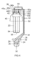
Fig. 3 eingeführten Bezugszeichen für die inFig. 4 dargestellte zweite Ausführungsform eines erfindungsgemäßen Adapters übernommen. Anstelle eines Anschlusses 44 sind nunmehr zwei Anschlüsse 44a und 44b vorhanden, die zur Verdeutlichung nebeneinander eingezeichnet sind, obwohl sie tatsächlich hintereinander angeordnet sind. Entsprechendes gilt für den Anschluss 46, und die entsprechenden Zuleitungen 60 und 66. - Die in
Fig. 4 dargestellte Ausführungsform eines erfindungsgemäßen Adapters 20 ist für den Betrieb einer Kompaktleuchtstofflampe 22 mit einem Stiftsockel ausgelegt. Sie umfasst weiterhin ein elektronisches Vorschaltgerät 58, das zwischen den ersten 28 und den zweiten Anschluss 30 des Schraubgewindes 26 und die ersten 44a, 44b und die zweiten Anschlüsse 46a, 46b der Koppelvorrichtung 42 gekoppelt ist. Über die Leitungen 60a, 60b und 66a, 66b kann eine Vorheizung der Wendeln der Kompaktleuchtstofflampe 22 realisiert werden. - Der Schirm 48 wird durch das Einclipsen der Kompaktleuchtstofflampe 22 in die Fassung 36 am Adapter 20 fixiert.
- Bei beiden Ausführungsformen kann vorgesehen sein, dass der Schirm bereits mit dem Adapter, bevorzugt mit der Fassung 36 gekoppelt ist, so dass er nicht erst durch das Einsetzen einer Kompaktleuchtstofflampe 22 fixiert wird.
- Durch eine nicht dargestellte Abstützvorrichtung kann der Adapter 20 zur Vermeidung von Schwingungen gegen eine Leuchte abgestützt werden, in die der Adapter 20 eingesetzt ist.
Claims (13)
- Adapter (20) für mindestens eine Kompaktleuchtstofflampe (22), wobei der Adapter (20) umfasst:- einen Schraubgewindesockel (24) zur Befestigung des Adapters (20) in einer Schraubfassung, wobei der Schraubgewindesockel (24) ein Schraubgewinde (26) aufweist mit einem ersten Anschluss (28) zum Anschließen an ein Bezugspotential und einen zweiten Anschluss (30) zum Anschließen an eine Versorgungsspannung sowie eine Befestigungseinheit (32);- mindestens einen Haltebügel (34) mit einem ersten (38) und einem zweiten Abschnitt (40), wobei der erste Abschnitt (38) mit der Befestigungseinheit (32) des Schraubgewindesockels (24) gekoppelt ist; und- mindestens eine Fassung (36) für die Kompaktleuchtstofflampe (22), die mit dem zweiten Abschnitt (40) des Haltebügels (34) gekoppelt ist, wobei die Fassung (36) eine Koppelvorrichtung (42) zum Koppeln mit der Kompaktleuchtstofflampe (22) aufweist, wobei die Koppelvorrichtung (42) eine Kopplungsseite aufweist, die in die Richtung zum Schraubgewindesockel (24) gerichtet ist, wobei die Koppelvorrichtung (42) mindestens einen ersten Anschluss (44) aufweist, der mit dem ersten Anschluss (28) des Schraubgewindes, und mindestens einen zweiten Anschluss (46), der mit dem zweiten Anschluss (30) des Schraubgewindes (26) gekoppelt ist, wobei der Abstand zwischen der Fassung (36) und dem Schraubgewindesockel (24) so bemessen ist, dass ein Einsetzen der Kompaktleuchtstofflampe (22) in die Fassung (36) ermöglicht ist.
- Adapter (20) nach Anspruch 1,
dadurch gekennzeichnet,
dass er weiterhin eine Wärmestauvorrichtung (48), insbesondere eine schirmförmige Wärmestauvorrichtung (48), umfasst. - Adapter (20) nach Anspruch 2,
dadurch gekennzeichnet,
dass die Wärmestauvorrichtung (48) mit der Lampenfassung (36) gekoppelt ist. - Adapter (20) nach Anspruch 2,
dadurch gekennzeichnet,
dass die Wärmestauvorrichtung (48) ausgelegt ist, mit der Lampenfassung (36), insbesondere durch Einsetzen der Kompaktleuchtstofflampe (22), gekoppelt zu werden. - Adapter (20) nach einem der vorhergehenden Ansprüche,
dadurch gekennzeichnet,
dass die Fassung (36) für eine Kompaktleuchtstofflampe (22) mit einem Schraubgewinde (26) ausgelegt ist. - Adapter (20) nach einem der Ansprüche 1 bis 4,
dadurch gekennzeichnet,
dass die Fassung (36) für eine Kompaktleuchtstofflampe (22) mit einem Stiftsockel ausgelegt ist. - Adapter (20) nach einem der vorhergehenden Ansprüche,
dadurch gekennzeichnet,
dass er weiterhin mindestens eine erste (50) und eine zweite Verbindungsleitung (52) umfasst, wobei die erste Verbindungsleitung (50) zwischen den ersten Anschluss (28) des Schraubgewindes (26) und den mindestens einen ersten Anschluss (44) der Koppelvorrichtung (42) gekoppelt ist und wobei die zweite Verbindungsleitung (52) zwischen den mindestens einen zweiten Anschluss (30) des Schraubgewindes (26) und den zweiten Anschluss (46) der Koppelvorrichtung (42) gekoppelt ist. - Adapter (20) nach Anspruch 7,
dadurch gekennzeichnet,
dass die erste (50) und die zweite Verbindungsleitung (52) im oder am Haltebügel (34) geführt sind. - Adapter (20) nach einem der vorhergehenden Ansprüche,
dadurch gekennzeichnet,
dass er weiterhin ein elektronisches Vorschaltgerät (58) umfasst, das zwischen den ersten (28) und den zweiten Anschluss (30) des Schraubgewindes (26) und den mindestens einen ersten (44) und den mindestens einen zweiten Anschluss (46) der Koppelvorrichtung (42) gekoppelt ist. - Adapter (20) nach einem der vorhergehenden Ansprüche,
dadurch gekennzeichnet,
dass er weiterhin eine Isolierung (54) für die Kompaktleuchtstofflampe (22) umfasst. - Adapter (20) nach Anspruch 10,
dadurch gekennzeichnet,
dass die Isolierung (54) auf den Kolbenbogen (56) der Kompaktleuchtstofflampe (22) aufbringbar ist. - Adapter (20) nach einem der Ansprüche 10 oder 11,
dadurch gekennzeichnet,
dass die Isolierung (54) Silikon, insbesondere transparentes Silikon, umfasst. - Adapter (20) nach einem der vorhergehenden Ansprüche,
dadurch gekennzeichnet,
dass er weiterhin eine Abstützvorrichtung umfasst, die ausgelegt ist, den Adapter (20) gegen eine Leuchte abzustützen, in die der Adapter (20) eingesetzt ist.
Applications Claiming Priority (1)
| Application Number | Priority Date | Filing Date | Title |
|---|---|---|---|
| DE102009006549A DE102009006549B3 (de) | 2009-01-29 | 2009-01-29 | Adapter für mindestens eine Kompaktleuchtstofflampe |
Publications (2)
| Publication Number | Publication Date |
|---|---|
| EP2214270A1 true EP2214270A1 (de) | 2010-08-04 |
| EP2214270B1 EP2214270B1 (de) | 2011-05-25 |
Family
ID=42154671
Family Applications (1)
| Application Number | Title | Priority Date | Filing Date |
|---|---|---|---|
| EP10150483A Active EP2214270B1 (de) | 2009-01-29 | 2010-01-12 | Adapter für mindestens eine Kompaktleuchtstofflampe |
Country Status (4)
| Country | Link |
|---|---|
| EP (1) | EP2214270B1 (de) |
| CN (1) | CN101794693A (de) |
| AT (1) | ATE511228T1 (de) |
| DE (1) | DE102009006549B3 (de) |
Citations (4)
| Publication number | Priority date | Publication date | Assignee | Title |
|---|---|---|---|---|
| US5458505A (en) * | 1994-02-03 | 1995-10-17 | Prager; Jay H. | Lamp cooling system |
| US6350046B1 (en) * | 1999-07-22 | 2002-02-26 | Kenneth Lau | Light fixture |
| US20050259419A1 (en) * | 2004-05-22 | 2005-11-24 | Ruben Sandoval | Replacement lighting fixture using multiple florescent bulbs |
| GB2436138A (en) * | 2006-03-16 | 2007-09-19 | George Foster | pendant light adaptor |
Family Cites Families (7)
| Publication number | Priority date | Publication date | Assignee | Title |
|---|---|---|---|---|
| DE8004802U1 (de) * | 1980-02-22 | 1980-06-12 | Patent-Treuhand-Gesellschaft Fuer Elektrische Gluehlampen Mbh, 8000 Muenchen | Adaptervorschaltgeraet fuer eine einsockelige entladungslampe |
| DE8337093U1 (de) * | 1983-12-23 | 1985-05-30 | Patent-Treuhand-Gesellschaft für elektrische Glühlampen mbH, 8000 München | Zwischensockel fuer eine einseitig gesockelte entladungslampe |
| DE4119567A1 (de) * | 1991-06-14 | 1991-10-17 | Czerny Heribert | Adapter fuer die nutzung normaler lampenfassungen fuer niedervolt-halogenlampen |
| CN2319936Y (zh) * | 1998-01-24 | 1999-05-19 | 樊邦弘 | 一种装饰灯连接装置 |
| DE19822460A1 (de) * | 1998-05-19 | 1999-11-25 | Patent Treuhand Ges Fuer Elektrische Gluehlampen Mbh | Adapter für ringförmige Leuchtstofflampen mit integrierter Vorschalt- und Zündanordnung |
| US6059593A (en) * | 1998-08-12 | 2000-05-09 | Angelo Brothers Company | Adapter and socket assembly for a compact fluorescent lamp |
| DE102006006346A1 (de) * | 2006-02-08 | 2007-09-06 | Daniel Stephan | Mittel zur adaptiven Verbindung mit einer Glühbirnenfassung zur Elektrizitätsversorgung von einem Elektrogerät |
-
2009
- 2009-01-29 DE DE102009006549A patent/DE102009006549B3/de not_active Expired - Fee Related
-
2010
- 2010-01-12 AT AT10150483T patent/ATE511228T1/de active
- 2010-01-12 EP EP10150483A patent/EP2214270B1/de active Active
- 2010-01-28 CN CN201010105814A patent/CN101794693A/zh active Pending
Patent Citations (4)
| Publication number | Priority date | Publication date | Assignee | Title |
|---|---|---|---|---|
| US5458505A (en) * | 1994-02-03 | 1995-10-17 | Prager; Jay H. | Lamp cooling system |
| US6350046B1 (en) * | 1999-07-22 | 2002-02-26 | Kenneth Lau | Light fixture |
| US20050259419A1 (en) * | 2004-05-22 | 2005-11-24 | Ruben Sandoval | Replacement lighting fixture using multiple florescent bulbs |
| GB2436138A (en) * | 2006-03-16 | 2007-09-19 | George Foster | pendant light adaptor |
Also Published As
| Publication number | Publication date |
|---|---|
| CN101794693A (zh) | 2010-08-04 |
| ATE511228T1 (de) | 2011-06-15 |
| EP2214270B1 (de) | 2011-05-25 |
| DE102009006549B3 (de) | 2010-12-09 |
Similar Documents
| Publication | Publication Date | Title |
|---|---|---|
| EP2436975B1 (de) | LED-Leuchte | |
| EP1721102B1 (de) | Lampe | |
| DE102008052869B4 (de) | Leuchte mit LED-Tragschiene | |
| DE102009040115B4 (de) | Anordnung von Lampenfassung und Lampensockel | |
| EP2491295B1 (de) | Linienlampe | |
| DE19607208C2 (de) | Leuchtstofflampe mit auswechselbarem Leuchtteil | |
| DE102004011974A1 (de) | Leuchtmittel für eine Beleuchtungseinrichtung | |
| DE102018123968B4 (de) | Beleuchtungsvorrichtung mit einer Light-Engine aus einem Streifen | |
| WO2007099124A1 (de) | Lampe mit einer einbaulampe | |
| EP2214270B1 (de) | Adapter für mindestens eine Kompaktleuchtstofflampe | |
| DE202016107013U1 (de) | Leuchteinheit, insbesondere für eine Schirmleuchte, und Leuchte, insbesondere Schirmleuchte, mit einer Leuchteinheit | |
| DE202021102682U1 (de) | Lampenfassung mit Belüftungskanal | |
| DE102015204716B4 (de) | Röhrenlampe mit einer Lampenröhre | |
| DE102010053654B4 (de) | Beleuchtungseinrichtung | |
| DE102010031008A1 (de) | LED-Leuchte | |
| DE60034284T2 (de) | Lampe mit Schraubsockel und im Sockelgehäuse enthaltene Elektronik, sowie Verfahren zur deren Herstellung | |
| DE102016107147B4 (de) | Schaltschrankleuchte mit verstellbarer Leuchtmittelplatine | |
| EP3027956A1 (de) | Led-modul | |
| DE102013104150B4 (de) | Leuchtmittelhalterung und Verfahren zu deren Montage | |
| DE102013204041A1 (de) | LED-Leuchtmittel | |
| DE102011016763B3 (de) | Beleuchtungseinrichtung, Leuchtkörperhalter und Leuchtkörper dafür | |
| DE202006007819U1 (de) | Elektrische Lampe | |
| DE202009000002U1 (de) | Baugruppe für eine Hochleistungs-LED-Lampe sowie Chipträger für eine solche Lampe | |
| DE202014100030U1 (de) | LED-Nachrüstsatz für Leuchten mit Fluoreszenzröhren | |
| DE102014014005A1 (de) | Vorrichtung zur Erdung eines Leuchtmittels |
Legal Events
| Date | Code | Title | Description |
|---|---|---|---|
| PUAI | Public reference made under article 153(3) epc to a published international application that has entered the european phase |
Free format text: ORIGINAL CODE: 0009012 |
|
| AK | Designated contracting states |
Kind code of ref document: A1 Designated state(s): AT BE BG CH CY CZ DE DK EE ES FI FR GB GR HR HU IE IS IT LI LT LU LV MC MK MT NL NO PL PT RO SE SI SK SM TR |
|
| AX | Request for extension of the european patent |
Extension state: AL BA RS |
|
| 17P | Request for examination filed |
Effective date: 20100906 |
|
| RIC1 | Information provided on ipc code assigned before grant |
Ipc: H01R 33/94 20060101AFI20101011BHEP Ipc: H01R 33/945 20060101ALI20101011BHEP |
|
| GRAP | Despatch of communication of intention to grant a patent |
Free format text: ORIGINAL CODE: EPIDOSNIGR1 |
|
| GRAS | Grant fee paid |
Free format text: ORIGINAL CODE: EPIDOSNIGR3 |
|
| GRAA | (expected) grant |
Free format text: ORIGINAL CODE: 0009210 |
|
| AK | Designated contracting states |
Kind code of ref document: B1 Designated state(s): AT BE BG CH CY CZ DE DK EE ES FI FR GB GR HR HU IE IS IT LI LT LU LV MC MK MT NL NO PL PT RO SE SI SK SM TR |
|
| REG | Reference to a national code |
Ref country code: GB Ref legal event code: FG4D Free format text: NOT ENGLISH |
|
| REG | Reference to a national code |
Ref country code: CH Ref legal event code: EP |
|
| REG | Reference to a national code |
Ref country code: IE Ref legal event code: FG4D Free format text: LANGUAGE OF EP DOCUMENT: GERMAN |
|
| REG | Reference to a national code |
Ref country code: DE Ref legal event code: R096 Ref document number: 502010000026 Country of ref document: DE Effective date: 20110707 |
|
| REG | Reference to a national code |
Ref country code: NL Ref legal event code: VDEP Effective date: 20110525 |
|
| PG25 | Lapsed in a contracting state [announced via postgrant information from national office to epo] |
Ref country code: PT Free format text: LAPSE BECAUSE OF FAILURE TO SUBMIT A TRANSLATION OF THE DESCRIPTION OR TO PAY THE FEE WITHIN THE PRESCRIBED TIME-LIMIT Effective date: 20110926 Ref country code: HR Free format text: LAPSE BECAUSE OF FAILURE TO SUBMIT A TRANSLATION OF THE DESCRIPTION OR TO PAY THE FEE WITHIN THE PRESCRIBED TIME-LIMIT Effective date: 20110525 Ref country code: NO Free format text: LAPSE BECAUSE OF FAILURE TO SUBMIT A TRANSLATION OF THE DESCRIPTION OR TO PAY THE FEE WITHIN THE PRESCRIBED TIME-LIMIT Effective date: 20110825 Ref country code: SE Free format text: LAPSE BECAUSE OF FAILURE TO SUBMIT A TRANSLATION OF THE DESCRIPTION OR TO PAY THE FEE WITHIN THE PRESCRIBED TIME-LIMIT Effective date: 20110525 Ref country code: LT Free format text: LAPSE BECAUSE OF FAILURE TO SUBMIT A TRANSLATION OF THE DESCRIPTION OR TO PAY THE FEE WITHIN THE PRESCRIBED TIME-LIMIT Effective date: 20110525 |
|
| PG25 | Lapsed in a contracting state [announced via postgrant information from national office to epo] |
Ref country code: CY Free format text: LAPSE BECAUSE OF FAILURE TO SUBMIT A TRANSLATION OF THE DESCRIPTION OR TO PAY THE FEE WITHIN THE PRESCRIBED TIME-LIMIT Effective date: 20110525 Ref country code: SI Free format text: LAPSE BECAUSE OF FAILURE TO SUBMIT A TRANSLATION OF THE DESCRIPTION OR TO PAY THE FEE WITHIN THE PRESCRIBED TIME-LIMIT Effective date: 20110525 Ref country code: LV Free format text: LAPSE BECAUSE OF FAILURE TO SUBMIT A TRANSLATION OF THE DESCRIPTION OR TO PAY THE FEE WITHIN THE PRESCRIBED TIME-LIMIT Effective date: 20110525 Ref country code: IS Free format text: LAPSE BECAUSE OF FAILURE TO SUBMIT A TRANSLATION OF THE DESCRIPTION OR TO PAY THE FEE WITHIN THE PRESCRIBED TIME-LIMIT Effective date: 20110925 Ref country code: GR Free format text: LAPSE BECAUSE OF FAILURE TO SUBMIT A TRANSLATION OF THE DESCRIPTION OR TO PAY THE FEE WITHIN THE PRESCRIBED TIME-LIMIT Effective date: 20110826 Ref country code: ES Free format text: LAPSE BECAUSE OF FAILURE TO SUBMIT A TRANSLATION OF THE DESCRIPTION OR TO PAY THE FEE WITHIN THE PRESCRIBED TIME-LIMIT Effective date: 20110905 Ref country code: FI Free format text: LAPSE BECAUSE OF FAILURE TO SUBMIT A TRANSLATION OF THE DESCRIPTION OR TO PAY THE FEE WITHIN THE PRESCRIBED TIME-LIMIT Effective date: 20110525 |
|
| REG | Reference to a national code |
Ref country code: IE Ref legal event code: FD4D |
|
| PG25 | Lapsed in a contracting state [announced via postgrant information from national office to epo] |
Ref country code: NL Free format text: LAPSE BECAUSE OF FAILURE TO SUBMIT A TRANSLATION OF THE DESCRIPTION OR TO PAY THE FEE WITHIN THE PRESCRIBED TIME-LIMIT Effective date: 20110525 |
|
| PG25 | Lapsed in a contracting state [announced via postgrant information from national office to epo] |
Ref country code: IE Free format text: LAPSE BECAUSE OF FAILURE TO SUBMIT A TRANSLATION OF THE DESCRIPTION OR TO PAY THE FEE WITHIN THE PRESCRIBED TIME-LIMIT Effective date: 20110525 Ref country code: EE Free format text: LAPSE BECAUSE OF FAILURE TO SUBMIT A TRANSLATION OF THE DESCRIPTION OR TO PAY THE FEE WITHIN THE PRESCRIBED TIME-LIMIT Effective date: 20110525 Ref country code: CZ Free format text: LAPSE BECAUSE OF FAILURE TO SUBMIT A TRANSLATION OF THE DESCRIPTION OR TO PAY THE FEE WITHIN THE PRESCRIBED TIME-LIMIT Effective date: 20110525 |
|
| REG | Reference to a national code |
Ref country code: DE Ref legal event code: R081 Ref document number: 502010000026 Country of ref document: DE Owner name: OSRAM GMBH, DE Free format text: FORMER OWNER: OSRAM GESELLSCHAFT MIT BESCHRAENKTER HAFTUNG, 81543 MUENCHEN, DE Effective date: 20111214 |
|
| PG25 | Lapsed in a contracting state [announced via postgrant information from national office to epo] |
Ref country code: PL Free format text: LAPSE BECAUSE OF FAILURE TO SUBMIT A TRANSLATION OF THE DESCRIPTION OR TO PAY THE FEE WITHIN THE PRESCRIBED TIME-LIMIT Effective date: 20110525 Ref country code: SK Free format text: LAPSE BECAUSE OF FAILURE TO SUBMIT A TRANSLATION OF THE DESCRIPTION OR TO PAY THE FEE WITHIN THE PRESCRIBED TIME-LIMIT Effective date: 20110525 |
|
| PLBE | No opposition filed within time limit |
Free format text: ORIGINAL CODE: 0009261 |
|
| STAA | Information on the status of an ep patent application or granted ep patent |
Free format text: STATUS: NO OPPOSITION FILED WITHIN TIME LIMIT |
|
| 26N | No opposition filed |
Effective date: 20120228 |
|
| REG | Reference to a national code |
Ref country code: DE Ref legal event code: R097 Ref document number: 502010000026 Country of ref document: DE Effective date: 20120228 |
|
| PGFP | Annual fee paid to national office [announced via postgrant information from national office to epo] |
Ref country code: IT Payment date: 20120131 Year of fee payment: 3 |
|
| BERE | Be: lapsed |
Owner name: OSRAM G.M.B.H. Effective date: 20120131 |
|
| PG25 | Lapsed in a contracting state [announced via postgrant information from national office to epo] |
Ref country code: MC Free format text: LAPSE BECAUSE OF NON-PAYMENT OF DUE FEES Effective date: 20120131 |
|
| PG25 | Lapsed in a contracting state [announced via postgrant information from national office to epo] |
Ref country code: BE Free format text: LAPSE BECAUSE OF NON-PAYMENT OF DUE FEES Effective date: 20120131 |
|
| PG25 | Lapsed in a contracting state [announced via postgrant information from national office to epo] |
Ref country code: MK Free format text: LAPSE BECAUSE OF FAILURE TO SUBMIT A TRANSLATION OF THE DESCRIPTION OR TO PAY THE FEE WITHIN THE PRESCRIBED TIME-LIMIT Effective date: 20110525 |
|
| REG | Reference to a national code |
Ref country code: DE Ref legal event code: R081 Ref document number: 502010000026 Country of ref document: DE Owner name: OSRAM GMBH, DE Free format text: FORMER OWNER: OSRAM AG, 81543 MUENCHEN, DE Effective date: 20130205 |
|
| PGFP | Annual fee paid to national office [announced via postgrant information from national office to epo] |
Ref country code: FR Payment date: 20130213 Year of fee payment: 4 Ref country code: DE Payment date: 20130122 Year of fee payment: 4 |
|
| PG25 | Lapsed in a contracting state [announced via postgrant information from national office to epo] |
Ref country code: BG Free format text: LAPSE BECAUSE OF FAILURE TO SUBMIT A TRANSLATION OF THE DESCRIPTION OR TO PAY THE FEE WITHIN THE PRESCRIBED TIME-LIMIT Effective date: 20110825 |
|
| PG25 | Lapsed in a contracting state [announced via postgrant information from national office to epo] |
Ref country code: MT Free format text: LAPSE BECAUSE OF FAILURE TO SUBMIT A TRANSLATION OF THE DESCRIPTION OR TO PAY THE FEE WITHIN THE PRESCRIBED TIME-LIMIT Effective date: 20110525 |
|
| REG | Reference to a national code |
Ref country code: DE Ref legal event code: R081 Ref document number: 502010000026 Country of ref document: DE Owner name: OSRAM GMBH, DE Free format text: FORMER OWNER: OSRAM GMBH, 81543 MUENCHEN, DE Effective date: 20130829 |
|
| PG25 | Lapsed in a contracting state [announced via postgrant information from national office to epo] |
Ref country code: TR Free format text: LAPSE BECAUSE OF FAILURE TO SUBMIT A TRANSLATION OF THE DESCRIPTION OR TO PAY THE FEE WITHIN THE PRESCRIBED TIME-LIMIT Effective date: 20110525 |
|
| PG25 | Lapsed in a contracting state [announced via postgrant information from national office to epo] |
Ref country code: SM Free format text: LAPSE BECAUSE OF FAILURE TO SUBMIT A TRANSLATION OF THE DESCRIPTION OR TO PAY THE FEE WITHIN THE PRESCRIBED TIME-LIMIT Effective date: 20110525 Ref country code: LU Free format text: LAPSE BECAUSE OF NON-PAYMENT OF DUE FEES Effective date: 20120112 |
|
| PG25 | Lapsed in a contracting state [announced via postgrant information from national office to epo] |
Ref country code: HU Free format text: LAPSE BECAUSE OF FAILURE TO SUBMIT A TRANSLATION OF THE DESCRIPTION OR TO PAY THE FEE WITHIN THE PRESCRIBED TIME-LIMIT Effective date: 20100112 |
|
| REG | Reference to a national code |
Ref country code: DE Ref legal event code: R119 Ref document number: 502010000026 Country of ref document: DE |
|
| REG | Reference to a national code |
Ref country code: CH Ref legal event code: PL |
|
| GBPC | Gb: european patent ceased through non-payment of renewal fee |
Effective date: 20140112 |
|
| REG | Reference to a national code |
Ref country code: DE Ref legal event code: R119 Ref document number: 502010000026 Country of ref document: DE Effective date: 20140801 |
|
| PG25 | Lapsed in a contracting state [announced via postgrant information from national office to epo] |
Ref country code: CH Free format text: LAPSE BECAUSE OF NON-PAYMENT OF DUE FEES Effective date: 20140131 Ref country code: LI Free format text: LAPSE BECAUSE OF NON-PAYMENT OF DUE FEES Effective date: 20140131 Ref country code: DE Free format text: LAPSE BECAUSE OF NON-PAYMENT OF DUE FEES Effective date: 20140801 |
|
| REG | Reference to a national code |
Ref country code: FR Ref legal event code: ST Effective date: 20140930 |
|
| PG25 | Lapsed in a contracting state [announced via postgrant information from national office to epo] |
Ref country code: GB Free format text: LAPSE BECAUSE OF NON-PAYMENT OF DUE FEES Effective date: 20140112 Ref country code: FR Free format text: LAPSE BECAUSE OF NON-PAYMENT OF DUE FEES Effective date: 20140131 |
|
| REG | Reference to a national code |
Ref country code: AT Ref legal event code: MM01 Ref document number: 511228 Country of ref document: AT Kind code of ref document: T Effective date: 20150112 |
|
| PG25 | Lapsed in a contracting state [announced via postgrant information from national office to epo] |
Ref country code: AT Free format text: LAPSE BECAUSE OF NON-PAYMENT OF DUE FEES Effective date: 20150112 |
|
| PG25 | Lapsed in a contracting state [announced via postgrant information from national office to epo] |
Ref country code: IT Free format text: LAPSE BECAUSE OF NON-PAYMENT OF DUE FEES Effective date: 20140112 |