EP2214052A2 - Flüssigkristallanzeigevorrichtung - Google Patents
Flüssigkristallanzeigevorrichtung Download PDFInfo
- Publication number
- EP2214052A2 EP2214052A2 EP10001067A EP10001067A EP2214052A2 EP 2214052 A2 EP2214052 A2 EP 2214052A2 EP 10001067 A EP10001067 A EP 10001067A EP 10001067 A EP10001067 A EP 10001067A EP 2214052 A2 EP2214052 A2 EP 2214052A2
- Authority
- EP
- European Patent Office
- Prior art keywords
- liquid crystal
- cooler
- detector
- temperature
- output
- Prior art date
- Legal status (The legal status is an assumption and is not a legal conclusion. Google has not performed a legal analysis and makes no representation as to the accuracy of the status listed.)
- Withdrawn
Links
- 239000004973 liquid crystal related substance Substances 0.000 title claims abstract description 83
- 230000007423 decrease Effects 0.000 claims abstract description 5
- 230000003213 activating effect Effects 0.000 claims abstract description 3
- 238000001816 cooling Methods 0.000 claims abstract description 3
- 238000000034 method Methods 0.000 description 10
- 238000005286 illumination Methods 0.000 description 7
- 239000002826 coolant Substances 0.000 description 6
- 238000001514 detection method Methods 0.000 description 5
- 239000006200 vaporizer Substances 0.000 description 5
- 238000010586 diagram Methods 0.000 description 4
- 238000009434 installation Methods 0.000 description 4
- 230000000694 effects Effects 0.000 description 3
- 239000011521 glass Substances 0.000 description 3
- 230000007613 environmental effect Effects 0.000 description 2
- 238000001704 evaporation Methods 0.000 description 2
- 230000008020 evaporation Effects 0.000 description 2
- 230000017525 heat dissipation Effects 0.000 description 2
- 239000007788 liquid Substances 0.000 description 2
- 238000005070 sampling Methods 0.000 description 2
- 238000009423 ventilation Methods 0.000 description 2
- 238000004078 waterproofing Methods 0.000 description 2
- 239000000428 dust Substances 0.000 description 1
- 230000001678 irradiating effect Effects 0.000 description 1
- 239000010687 lubricating oil Substances 0.000 description 1
- 239000000203 mixture Substances 0.000 description 1
- 239000003921 oil Substances 0.000 description 1
- 239000007787 solid Substances 0.000 description 1
- 230000000007 visual effect Effects 0.000 description 1
Images


Classifications
-
- G—PHYSICS
- G02—OPTICS
- G02F—OPTICAL DEVICES OR ARRANGEMENTS FOR THE CONTROL OF LIGHT BY MODIFICATION OF THE OPTICAL PROPERTIES OF THE MEDIA OF THE ELEMENTS INVOLVED THEREIN; NON-LINEAR OPTICS; FREQUENCY-CHANGING OF LIGHT; OPTICAL LOGIC ELEMENTS; OPTICAL ANALOGUE/DIGITAL CONVERTERS
- G02F1/00—Devices or arrangements for the control of the intensity, colour, phase, polarisation or direction of light arriving from an independent light source, e.g. switching, gating or modulating; Non-linear optics
- G02F1/01—Devices or arrangements for the control of the intensity, colour, phase, polarisation or direction of light arriving from an independent light source, e.g. switching, gating or modulating; Non-linear optics for the control of the intensity, phase, polarisation or colour
- G02F1/13—Devices or arrangements for the control of the intensity, colour, phase, polarisation or direction of light arriving from an independent light source, e.g. switching, gating or modulating; Non-linear optics for the control of the intensity, phase, polarisation or colour based on liquid crystals, e.g. single liquid crystal display cells
- G02F1/133—Constructional arrangements; Operation of liquid crystal cells; Circuit arrangements
- G02F1/1333—Constructional arrangements; Manufacturing methods
- G02F1/133382—Heating or cooling of liquid crystal cells other than for activation, e.g. circuits or arrangements for temperature control, stabilisation or uniform distribution over the cell
- G02F1/133385—Heating or cooling of liquid crystal cells other than for activation, e.g. circuits or arrangements for temperature control, stabilisation or uniform distribution over the cell with cooling means, e.g. fans
-
- G—PHYSICS
- G02—OPTICS
- G02F—OPTICAL DEVICES OR ARRANGEMENTS FOR THE CONTROL OF LIGHT BY MODIFICATION OF THE OPTICAL PROPERTIES OF THE MEDIA OF THE ELEMENTS INVOLVED THEREIN; NON-LINEAR OPTICS; FREQUENCY-CHANGING OF LIGHT; OPTICAL LOGIC ELEMENTS; OPTICAL ANALOGUE/DIGITAL CONVERTERS
- G02F2201/00—Constructional arrangements not provided for in groups G02F1/00 - G02F7/00
- G02F2201/36—Airflow channels, e.g. constructional arrangements facilitating the flow of air
Definitions
- the present invention relates to a liquid crystal display apparatus, especially, a liquid crystal display apparatus for outdoor installation.
- the liquid crystal has a character between a solid and a liquid state.
- images are displayed by controlling the orientation of a liquid crystal by varying a voltage applied to the liquid crystal.
- the images can not be displayed correctly since the liquid crystal liquefies and lose its orientation.
- a composition adapted for outdoor installation for example, a waterproofing structure or a dustproof structure.
- a waterproofing structure for example, a waterproofing structure or a dustproof structure.
- the air can not circulate inside and outside of the display apparatus, it is difficult to emit a heat generated inside the apparatus, and it may cause a temperature rise inside its housing. Thereby, the temperature of the liquid crystal of the panel may rise.
- a transmissive liquid crystal display in order to improve visibility in outdoor, where under a strong light such as direct rays of the sun, it is necessary to make a display portion (screen) brighter than the usual. To make the display portion brighter, it is necessary to raise an output from the illuminating device (backlight etc.), accordingly the heat quantity from the illuminating device get larger. Thereby, the temperature of the liquid crystal may rise easily.
- the display when the liquid crystal display is installed outdoors, the display may be exposed to direct rays. When a strong outdoor daylight is irradiated on its display surface, the temperature of the liquid crystal of the display rises.
- a first liquid crystal display apparatus of the present invention comprises:
- a second liquid crystal display apparatus of the present invention comprises:
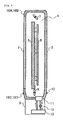
- Fig.1 is an outlined longitudinal sectional view of the liquid crystal display apparatus of the first embodiment.
- the liquid crystal display apparatus has a front glass 1 arranged at the front side of the display, a housing 2, and a cooler 3.
- a liquid crystal panel 5 In an interior space 4 surrounded by the front glass 1, the housing 2, and the cooler 3, a liquid crystal panel 5, a back light 6, ventilation fans 7 and 8 for circulating the air in the space 4, and the first temperature sensors 9A-9D detecting a surrounding temperature of the panel 5 are arranged.
- the panel 5 is arranged so that its display screen is located in the front side of the display, and thus a user can see the screen through the front glass 1.
- the back light 6 is arranged behind the panel 5, and irradiates the panel 5.
- the fan 7 is arranged at the upper part of the space 4, and the fan 8 is arranged at the lower part of the space 4.
- Each of the sensors 9A-9D is arranged near the corner of the front inner side of the housing 2.
- a second temperature sensor 10 for detecting the temperature of the setting position of a liquid crystal display is arranged in the back side of and outside of the housing 2.
- the cooler 3 has a vaporizer 11, a compressor 12, a radiator 13, and a coolant course.
- the coolant vaporized by the vaporizer 11 is sent to the compressor 12 through the coolant course, then compressed by the compressor 12, and becomes a hot gas.
- the coolant which is turned to a hot gas by the compressor 12 is sent to the radiator 13 through the coolant course, and is liquefied by a heat dissipation of the radiator 13 under a high pressure.
- the radiator 13 emits heat outside the liquid crystal display apparatus.
- the high pressure liquid liquefied at the radiator 13 is sent to the vaporizer 11 through a coolant course, and then evaporated by lowering its pressure in the vaporizer 11.
- the vaporizer 11 absorbs a heat of the interior space 4 as an evaporation heat.
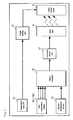
- FIG.2 an outlined block diagram of the above liquid crystal display apparatus is shown in Fig.2 .
- same marks are given to the portions already described in Fig.1 , and for such portions, detailed explanations are omitted hereafter.
- the liquid crystal display apparatus has an image signal input unit 14, an image display part 15, first temperature sensors 9A-9D, a second temperature sensor 10, a microcomputer 16, a luminosity control part 17, a backlight 6, and a liquid crystal panel 5.
- the image signal input unit 14 is connected to LAN (Local Area Network) for example, and when an image signal is input from LAN to the unit 14, it outputs an image signal of a DVI (Digital Visual Interface) format.
- the image display part 15 converts a signal from the unit 14 into a suitable format for the liquid crystal display panel 5 and outputs the signal to the panel 5. Then, an image is displayed in the panel 5.
- the backlight 6 irradiates a light from the back side of the liquid crystal display panel 5 in order to display an image by the panel 5.
- the backlight 6 is consisted by CCFL (Cold Cathode Fluorescent Lamp) for example.
- the microcomputer 16 outputs a backlight control signal which indicates a luminosity of the backlight 6 to the luminosity control part 17.
- the control part 17 outputs the PWM (Pulse Width Modulation) drive signal to the backlight 6 according to the backlight control signal from the microcomputer 16.
- the backlight 6 emits a light according to the PWM drive signal from the control part 17.
- the first temperature sensors 9A-9D and the second temperature sensor 10 are connected to the microcomputer 16, and the microcomputer 16 converts analog temperature detection signals from the sensors 9A-9D and the sensor 10 to digital signals. Further, the microcomputer 16 executes on/off controls of the ventilation fans 7 and 8, and the cooler 3.
- guaranteed operating temperature is defined in coolers, and the operation of the cooler is not guaranteed when a surrounding temperature (an air temperature on the emitting side of the cooler) is less than the lower limit of, or higher than the upper limit of the guaranteed temperature.
- the lower limit of the guaranteed temperature is defined considering that the lubricating oil used inside the cooler does not serve as a lubricator in low temperatures (for example, under 10 degrees Celsius) because the viscosity of the oil become too high.
- the temperature of the interior space 4 does not rise such that the liquid crystal of the liquid crystal panel 5 liquefies even if the cooler 3 is not operated, because the temperature of the space 4 does not raise so much in such cases.
- the liquid crystal display apparatus installed outdoors may be exposed to a direct sunlight and when the sunlight irradiates the display surface of the liquid crystal panel 5, the temperature of the liquid crystal of the panel 5 rises.
- the display apparatus has a waterproofing structure or a dust proofing structure, since the air-tightness of the interior space 4 is high, the temperature of the interior space 4 may become high is high even if the surrounding temperature of the apparatus is low because of a greenhouse effect. As a result, the temperature of the liquid crystal may rise to a liquefying temperature (approximately 70 degrees Celsius).
- the display surface of the liquid crystal panel 5 may receive direct sunlight entering perpendicularly for a long time when the display apparatus is installed facing its display screen southward because an outside temperature is low and the solar altitude is low. In this case, there is a possibility that the temperature of the liquid crystal of the panel 5 rise to a liquefaction temperature, even if the surrounding temperature of the apparatus is low.
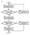
- the liquid crystal display apparatus of this embodiment executes a procedure shown in a flow chart of Fig.3 .
- the microcomputer 16 acquires a temperature information of four points inside the interior space 4 based on temperature detection signals from each of the first temperature sensors 9A-9D (step S10), and then determines whether at least one of four acquired temperature is equal to or more than a first threshold value (step S20).
- the microcomputer 16 sets the cooler off. In detail, under an assumption that the liquid crystal of the panel 5 does not liquefy even if the output of the backlight 6 is set to a normal setting, the microcomputer 16 keeps the cooler 3 off when the cooler 3 is currently off. When the cooler is currently on, the microcomputer 16 turns the cooler 3 to longer its operating life and to conserve energy. Further, when the output of the backlight 6 is currently in the normal setting, the microcomputer 16 maintains the normal setting. When the output is not in the normal setting, the microcomputer 16 turns it to the normal setting so that the visibility of the image screen improves (step S30). Then, it returns to step S10.
- step S20 If one of the temperature of the interior space 4 is equal to or more than the first threshold value ("yes" in step S20), presuming that the outdoor daylight is irradiated on a display surface of the panel 5 for a predetermined period, the microcomputer 16 acquires a surrounding temperature of the display apparatus based on the detecting signal from the second temperature sensor 10 (step S40), and determines whether the acquired temperature is less than a second threshold value or not (step S50).
- the second threshold value is set to a minimum guaranteed operating temperature of the cooler 3 or a predetermined temperature which is somewhat higher than the guaranteed temperature.
- the microcomputer sets the cooler 3 on. In detail, if the cooler 3 is currently on, the microcomputer keeps the cooler 3 on. If the cooler is currently off, the microcomputer turns the cooler in order not to liquefy the liquid crystal. Further, if the output of the backlight 6 is set to a normal setting, the microcomputer 16 keeps the setting normal. If the output level of the backlight 6 is set lower than the normal setting, the microcomputer turn the setting to the normal in order to assure a visibility under a strong sunlight (step S60). Then the procedure shown in the flow chart ends.
- the microcomputer sets the cooler 3 off. In detail, if the cooler 3 is currently off, the microcomputer 16 keeps the cooler 3 off, and if the cooler 3 is currently on, the microcomputer 16 turns the cooler 3 off. Further, if the output level of the backlight 6 is currently in the normal setting, the microcomputer 16 sets the output level lower than the normal setting because the liquid crystal of the panel 5 might liquefy if the cooler 3 is kept off while the output level of the backlight 6 is kept normal setting. If the level of the backlight 6 is currently in a level lower than the normal setting, the microcomputer 16 maintains the setting of backlight 6 (step S70). Then the procedure shown in the flow chart ends.
- step S10 the temperature information of four points of the interior space 4 may be acquired in a form of either momentary temperature or the average temperature in a predetermined period. If the average temperature is adapted, it can reduce effects from momentary noise or environmental change etc.
- the microcomputer 16 may keep on sampling the temperature detection signal from the first temperature sensors 9A-9D every second, then compute the average value acquired in the last 100 seconds.
- the surrounding temperature information of the display apparatus may be acquired in a form of either momentary temperature or the average temperature in a predetermined period. If the average temperature is adapted, it can reduce effects from momentary noise or environmental change as well.
- the microcomputer 16 may keep on sampling the temperature detection signal from the second temperature sensor 10 every second, then compute the average value acquired in the last 100 seconds.
- the temperature of the liquid crystal of the liquid crystal panel 5 rises is a heat emitted from the display apparatus itself (especially a heat from the backlight 6) or a heat caused by the irradiation of strong outdoor light (such as direct sunlight) to the display surface of the panel 5.
- a heat emitted from the display apparatus itself especially a heat from the backlight 6
- a heat caused by the irradiation of strong outdoor light such as direct sunlight
- the liquid crystal liquefies if the outdoor light irradiates the panel for a long time period.
- liquid crystal display apparatus of the present embodiment it is judged that the liquid crystal of the liquid crystal panel 5 might liquefy if the outdoor light irradiates the display surface of the panel for a predetermined period unless the backlight level is not lowered from the normal setting.
- Fig.4 is a longitudinal sectional view of the liquid crystal display of this embodiment.
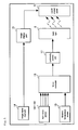
- Fig.5 is a block diagram of the liquid crystal display of this embodiment.
- same marks are given to the portions already described in Fig.1 .
- same marks are given to the portions already described in Fig.2 or Fig.4 .
- detailed explanations are omitted hereafter.
- the illumination sensors 18A-18D are newly arranged in the four corners of the front side perimeter side of the housing 2 instead of the first temperature sensors 9A-9D in the first embodiment.
- Fig.6 is a flow chart showing a procedure which the display apparatus of the present embodiment executes.
- same marks are given to the steps already described in Fig.3 , and for such steps, detailed explanations are omitted hereafter.
- steps S10 and S20 are omitted from the flow chart of Fig.3 and steps S15 and S25 are added instead.
- Step S15 the microcomputer 16 acquires the illumination information on the four corners of housing 2, based on the illumination detection signal from the sensors 18A-18D.
- Step S25 the microcomputer 16 determines whether one of the illumination detected at each corners is more than a third threshold value for a predetermined period or not.
- step S25 When it is determined “no” in step S25, assuming that the liquid crystal of the panel 5 does not liquefy even if the output level of the backlight is kept in normal setting, the microcomputer 16 turns the cooler 3 off, and then goes to step S30.
- step S40 When it is determined “yes” in step S25, assuming that the outdoor light is irradiating the display surface of the panel 5 for more than a predetermined time, it goes to step S40.
- the visibility of the display screen under a strong daylight can be secured, or liquefaction of the liquid crystal can be suppressed.
- the illumination information of four corners acquired in step S15 may be either momentary illumination or average illumination during a predetermined period.
Landscapes
- Physics & Mathematics (AREA)
- Nonlinear Science (AREA)
- Mathematical Physics (AREA)
- Chemical & Material Sciences (AREA)
- Crystallography & Structural Chemistry (AREA)
- General Physics & Mathematics (AREA)
- Optics & Photonics (AREA)
- Liquid Crystal (AREA)
- Devices For Indicating Variable Information By Combining Individual Elements (AREA)
- Liquid Crystal Display Device Control (AREA)
- Control Of Indicators Other Than Cathode Ray Tubes (AREA)
Applications Claiming Priority (1)
| Application Number | Priority Date | Filing Date | Title |
|---|---|---|---|
| JP2009022918A JP5219864B2 (ja) | 2009-02-03 | 2009-02-03 | 液晶表示装置 |
Publications (2)
| Publication Number | Publication Date |
|---|---|
| EP2214052A2 true EP2214052A2 (de) | 2010-08-04 |
| EP2214052A3 EP2214052A3 (de) | 2011-09-28 |
Family
ID=42139009
Family Applications (1)
| Application Number | Title | Priority Date | Filing Date |
|---|---|---|---|
| EP10001067A Withdrawn EP2214052A3 (de) | 2009-02-03 | 2010-02-02 | Flüssigkristallanzeigevorrichtung |
Country Status (3)
| Country | Link |
|---|---|
| US (1) | US20100194675A1 (de) |
| EP (1) | EP2214052A3 (de) |
| JP (1) | JP5219864B2 (de) |
Families Citing this family (6)
| Publication number | Priority date | Publication date | Assignee | Title |
|---|---|---|---|---|
| JP2012118130A (ja) * | 2010-11-29 | 2012-06-21 | Sanyo Electric Co Ltd | 表示装置及び電子機器 |
| JP2013160502A (ja) * | 2012-02-01 | 2013-08-19 | Panasonic Liquid Crystal Display Co Ltd | 温度センサを備える表示装置 |
| JP6171383B2 (ja) * | 2013-02-15 | 2017-08-02 | セイコーエプソン株式会社 | 電気光学装置及び電子機器 |
| US10117364B2 (en) | 2016-02-07 | 2018-10-30 | Display Logic USA Inc. | Display device with optically clear fluid disposed between display panel and display cover |
| CN109407377A (zh) * | 2018-10-26 | 2019-03-01 | 蚌埠国显科技有限公司 | 一种具有避免残像功能的液晶显示器 |
| TWI820976B (zh) * | 2022-10-20 | 2023-11-01 | 達擎股份有限公司 | 顯示裝置 |
Citations (1)
| Publication number | Priority date | Publication date | Assignee | Title |
|---|---|---|---|---|
| WO2009022918A1 (en) | 2007-08-10 | 2009-02-19 | Duke Engines Limited | Advance-retard mechanism for axial piston machine and axial piston machine incorporating such |
Family Cites Families (18)
| Publication number | Priority date | Publication date | Assignee | Title |
|---|---|---|---|---|
| JPH087338B2 (ja) * | 1990-04-17 | 1996-01-29 | パイオニア株式会社 | 画像表示装置 |
| JPH07154725A (ja) * | 1993-11-26 | 1995-06-16 | Sony Corp | 液晶映像表示装置 |
| US5502582A (en) * | 1994-09-02 | 1996-03-26 | Aavid Laboratories, Inc. | Light source cooler for LCD monitor |
| JP3212818B2 (ja) * | 1994-12-28 | 2001-09-25 | シャープ株式会社 | 電子冷却装置 |
| JPH0980393A (ja) * | 1995-09-19 | 1997-03-28 | Kokusai Electric Co Ltd | 液晶表示装置及びその制御方法 |
| JP3226450B2 (ja) * | 1995-11-30 | 2001-11-05 | ウエスト電気株式会社 | 遊戯機用液晶プロジェクタ |
| JP2000171773A (ja) * | 1998-12-02 | 2000-06-23 | Sharp Corp | 液晶表示装置 |
| US6825828B2 (en) * | 2001-02-23 | 2004-11-30 | General Digital Corporation | Backlit LCD monitor |
| JP2003043577A (ja) * | 2001-08-01 | 2003-02-13 | Sanyo Electric Co Ltd | 液晶プロジェクタ |
| JP2003315762A (ja) * | 2002-04-22 | 2003-11-06 | Ikegami Tsushinki Co Ltd | 保温冷却機能を有する液晶テレビモニタ装置 |
| JP2004325568A (ja) * | 2003-04-22 | 2004-11-18 | Fujitsu Hitachi Plasma Display Ltd | プラズマディスプレイ装置およびパワーモジュール |
| JP4462904B2 (ja) * | 2003-11-19 | 2010-05-12 | Necディスプレイソリューションズ株式会社 | 冷却機構、電子機器、プロジェクタ、および筐体内の冷却方法 |
| US20050212824A1 (en) * | 2004-03-25 | 2005-09-29 | Marcinkiewicz Walter M | Dynamic display control of a portable electronic device display |
| US8400607B2 (en) * | 2005-10-11 | 2013-03-19 | Barco N.V. | Display assemblies and methods of display |
| TWI331741B (en) * | 2006-10-14 | 2010-10-11 | Au Optronics Corp | System and driving method for color sequencial liquid crystal display (lcd) |
| JP5010311B2 (ja) * | 2007-02-28 | 2012-08-29 | Necディスプレイソリューションズ株式会社 | 投写型表示装置 |
| TWI354823B (en) * | 2007-09-17 | 2011-12-21 | Au Optronics Corp | Display device, manufacturing method thereof, cont |
| JP4766499B2 (ja) * | 2009-01-19 | 2011-09-07 | 三洋電機株式会社 | 屋外用画像表示装置 |
-
2009
- 2009-02-03 JP JP2009022918A patent/JP5219864B2/ja active Active
-
2010
- 2010-02-02 EP EP10001067A patent/EP2214052A3/de not_active Withdrawn
- 2010-02-03 US US12/699,293 patent/US20100194675A1/en not_active Abandoned
Patent Citations (1)
| Publication number | Priority date | Publication date | Assignee | Title |
|---|---|---|---|---|
| WO2009022918A1 (en) | 2007-08-10 | 2009-02-19 | Duke Engines Limited | Advance-retard mechanism for axial piston machine and axial piston machine incorporating such |
Also Published As
| Publication number | Publication date |
|---|---|
| US20100194675A1 (en) | 2010-08-05 |
| JP2010181486A (ja) | 2010-08-19 |
| EP2214052A3 (de) | 2011-09-28 |
| JP5219864B2 (ja) | 2013-06-26 |
Similar Documents
| Publication | Publication Date | Title |
|---|---|---|
| US9867253B2 (en) | Backlight adjustment system | |
| AU2022238796B2 (en) | Fan control for electronic display assemblies | |
| US20100194675A1 (en) | Liquid Crystal Display Apparatus | |
| JP5405908B2 (ja) | 表示装置 | |
| US8319936B2 (en) | Display device with cooling control | |
| US12105370B2 (en) | Fan control for electronic display assemblies | |
| EP2214462B1 (de) | Anzeigevorrichtung und Anzeigesystem | |
| US8700226B2 (en) | Method for driving a cooling fan within an electronic display | |
| US20120131936A1 (en) | Display apparatus and electronic equipment | |
| CN117095653B (zh) | 一种投影lcd屏保护系统 | |
| CN102768427A (zh) | 户外lcd显示设备及其温度调节系统 | |
| JP2011253057A (ja) | 表示装置 | |
| JP2010144975A (ja) | 屋外用表示装置およびこれを備えた空気調和装置の室外機 | |
| JP7026849B2 (ja) | 冷蔵庫 | |
| JP2012118131A (ja) | 表示装置 | |
| EP2954510B1 (de) | Displaygehäuse | |
| CN104122908B (zh) | 一种控温装置和方法 | |
| JP2008124284A (ja) | Led制御装置 | |
| JP2019149232A (ja) | 照明装置、照明装置を備える表示装置及び制御方法 | |
| WO2014147790A1 (ja) | 電子機器、電子機器の設定方法 | |
| CN103471206A (zh) | 一种户外广告机及其变频空调的变频控制方法 |
Legal Events
| Date | Code | Title | Description |
|---|---|---|---|
| PUAI | Public reference made under article 153(3) epc to a published international application that has entered the european phase |
Free format text: ORIGINAL CODE: 0009012 |
|
| AK | Designated contracting states |
Kind code of ref document: A2 Designated state(s): AT BE BG CH CY CZ DE DK EE ES FI FR GB GR HR HU IE IS IT LI LT LU LV MC MK MT NL NO PL PT RO SE SI SK SM TR |
|
| AX | Request for extension of the european patent |
Extension state: AL BA RS |
|
| PUAL | Search report despatched |
Free format text: ORIGINAL CODE: 0009013 |
|
| AK | Designated contracting states |
Kind code of ref document: A3 Designated state(s): AT BE BG CH CY CZ DE DK EE ES FI FR GB GR HR HU IE IS IT LI LT LU LV MC MK MT NL NO PL PT RO SE SI SK SM TR |
|
| AX | Request for extension of the european patent |
Extension state: AL BA RS |
|
| RIC1 | Information provided on ipc code assigned before grant |
Ipc: G02F 1/133 20060101AFI20110824BHEP |
|
| 17P | Request for examination filed |
Effective date: 20120130 |
|
| RIC1 | Information provided on ipc code assigned before grant |
Ipc: G02F 1/1333 20060101AFI20130603BHEP |
|
| GRAP | Despatch of communication of intention to grant a patent |
Free format text: ORIGINAL CODE: EPIDOSNIGR1 |
|
| INTG | Intention to grant announced |
Effective date: 20140702 |
|
| RAP1 | Party data changed (applicant data changed or rights of an application transferred) |
Owner name: SANYO ELECTRIC CO., LTD. |
|
| RIN1 | Information on inventor provided before grant (corrected) |
Inventor name: KONDO, TAKAHIRO Inventor name: YOSHIDA, TOMONORI Inventor name: SATO, HIDENORI |
|
| STAA | Information on the status of an ep patent application or granted ep patent |
Free format text: STATUS: THE APPLICATION IS DEEMED TO BE WITHDRAWN |
|
| 18D | Application deemed to be withdrawn |
Effective date: 20141113 |