EP2213435B1 - Dispositif de chauffage pour ébauches en plastique - Google Patents
Dispositif de chauffage pour ébauches en plastique Download PDFInfo
- Publication number
- EP2213435B1 EP2213435B1 EP10160126.8A EP10160126A EP2213435B1 EP 2213435 B1 EP2213435 B1 EP 2213435B1 EP 10160126 A EP10160126 A EP 10160126A EP 2213435 B1 EP2213435 B1 EP 2213435B1
- Authority
- EP
- European Patent Office
- Prior art keywords
- preforms
- resonator
- heating
- microwave
- preform
- Prior art date
- Legal status (The legal status is an assumption and is not a legal conclusion. Google has not performed a legal analysis and makes no representation as to the accuracy of the status listed.)
- Not-in-force
Links
- 238000010438 heat treatment Methods 0.000 title claims description 106
- 239000004033 plastic Substances 0.000 title description 16
- 229920003023 plastic Polymers 0.000 title description 16
- 238000000034 method Methods 0.000 claims description 37
- 239000004020 conductor Substances 0.000 claims description 19
- 230000005855 radiation Effects 0.000 claims description 17
- 238000009826 distribution Methods 0.000 claims description 12
- 238000000071 blow moulding Methods 0.000 claims description 11
- 239000012815 thermoplastic material Substances 0.000 claims 1
- 230000008901 benefit Effects 0.000 description 13
- XLYOFNOQVPJJNP-UHFFFAOYSA-N water Substances O XLYOFNOQVPJJNP-UHFFFAOYSA-N 0.000 description 11
- 230000008569 process Effects 0.000 description 10
- 238000012546 transfer Methods 0.000 description 7
- 238000007664 blowing Methods 0.000 description 6
- 238000001816 cooling Methods 0.000 description 6
- 238000011161 development Methods 0.000 description 6
- 238000004519 manufacturing process Methods 0.000 description 5
- 230000006978 adaptation Effects 0.000 description 3
- 238000009529 body temperature measurement Methods 0.000 description 3
- 230000000694 effects Effects 0.000 description 3
- 230000001681 protective effect Effects 0.000 description 3
- 230000001105 regulatory effect Effects 0.000 description 3
- 206010001497 Agitation Diseases 0.000 description 2
- IJGRMHOSHXDMSA-UHFFFAOYSA-N Atomic nitrogen Chemical compound N#N IJGRMHOSHXDMSA-UHFFFAOYSA-N 0.000 description 2
- 239000011324 bead Substances 0.000 description 2
- 235000013361 beverage Nutrition 0.000 description 2
- 239000000969 carrier Substances 0.000 description 2
- 238000013461 design Methods 0.000 description 2
- 230000005670 electromagnetic radiation Effects 0.000 description 2
- 238000005516 engineering process Methods 0.000 description 2
- 238000002372 labelling Methods 0.000 description 2
- 239000000463 material Substances 0.000 description 2
- 229920001296 polysiloxane Polymers 0.000 description 2
- 229920001169 thermoplastic Polymers 0.000 description 2
- 239000004416 thermosoftening plastic Substances 0.000 description 2
- 238000011144 upstream manufacturing Methods 0.000 description 2
- 229920001634 Copolyester Polymers 0.000 description 1
- 229920000219 Ethylene vinyl alcohol Polymers 0.000 description 1
- 239000004952 Polyamide Substances 0.000 description 1
- 239000004809 Teflon Substances 0.000 description 1
- 229920006362 Teflon® Polymers 0.000 description 1
- 230000009471 action Effects 0.000 description 1
- 239000000654 additive Substances 0.000 description 1
- 239000003570 air Substances 0.000 description 1
- 230000000712 assembly Effects 0.000 description 1
- 238000000429 assembly Methods 0.000 description 1
- 230000005540 biological transmission Effects 0.000 description 1
- 230000001143 conditioned effect Effects 0.000 description 1
- 230000001276 controlling effect Effects 0.000 description 1
- 239000002826 coolant Substances 0.000 description 1
- 239000000498 cooling water Substances 0.000 description 1
- 230000008878 coupling Effects 0.000 description 1
- 238000010168 coupling process Methods 0.000 description 1
- 238000005859 coupling reaction Methods 0.000 description 1
- 230000006378 damage Effects 0.000 description 1
- UFRKOOWSQGXVKV-UHFFFAOYSA-N ethene;ethenol Chemical compound C=C.OC=C UFRKOOWSQGXVKV-UHFFFAOYSA-N 0.000 description 1
- 239000004715 ethylene vinyl alcohol Substances 0.000 description 1
- 239000000835 fiber Substances 0.000 description 1
- 239000000945 filler Substances 0.000 description 1
- 239000012530 fluid Substances 0.000 description 1
- 230000001939 inductive effect Effects 0.000 description 1
- 238000003780 insertion Methods 0.000 description 1
- 230000037431 insertion Effects 0.000 description 1
- 238000005259 measurement Methods 0.000 description 1
- 239000007769 metal material Substances 0.000 description 1
- 229910052757 nitrogen Inorganic materials 0.000 description 1
- 230000000149 penetrating effect Effects 0.000 description 1
- 229920000058 polyacrylate Polymers 0.000 description 1
- 229920002647 polyamide Polymers 0.000 description 1
- 229920000515 polycarbonate Polymers 0.000 description 1
- 239000004417 polycarbonate Substances 0.000 description 1
- 229920000728 polyester Polymers 0.000 description 1
- 229920000098 polyolefin Polymers 0.000 description 1
- 230000004044 response Effects 0.000 description 1
- 238000000926 separation method Methods 0.000 description 1
- 239000007858 starting material Substances 0.000 description 1
- 238000003860 storage Methods 0.000 description 1
- 230000003797 telogen phase Effects 0.000 description 1
- 238000005496 tempering Methods 0.000 description 1
- 229920002554 vinyl polymer Polymers 0.000 description 1
- 238000010792 warming Methods 0.000 description 1
- 229910000859 α-Fe Inorganic materials 0.000 description 1
Images


Classifications
-
- B—PERFORMING OPERATIONS; TRANSPORTING
- B29—WORKING OF PLASTICS; WORKING OF SUBSTANCES IN A PLASTIC STATE IN GENERAL
- B29C—SHAPING OR JOINING OF PLASTICS; SHAPING OF MATERIAL IN A PLASTIC STATE, NOT OTHERWISE PROVIDED FOR; AFTER-TREATMENT OF THE SHAPED PRODUCTS, e.g. REPAIRING
- B29C49/00—Blow-moulding, i.e. blowing a preform or parison to a desired shape within a mould; Apparatus therefor
- B29C49/42—Component parts, details or accessories; Auxiliary operations
- B29C49/64—Heating or cooling preforms, parisons or blown articles
- B29C49/6409—Thermal conditioning of preforms
- B29C49/6418—Heating of preforms
-
- B—PERFORMING OPERATIONS; TRANSPORTING
- B29—WORKING OF PLASTICS; WORKING OF SUBSTANCES IN A PLASTIC STATE IN GENERAL
- B29B—PREPARATION OR PRETREATMENT OF THE MATERIAL TO BE SHAPED; MAKING GRANULES OR PREFORMS; RECOVERY OF PLASTICS OR OTHER CONSTITUENTS OF WASTE MATERIAL CONTAINING PLASTICS
- B29B13/00—Conditioning or physical treatment of the material to be shaped
- B29B13/02—Conditioning or physical treatment of the material to be shaped by heating
- B29B13/023—Half-products, e.g. films, plates
- B29B13/024—Hollow bodies, e.g. tubes or profiles
-
- B—PERFORMING OPERATIONS; TRANSPORTING
- B29—WORKING OF PLASTICS; WORKING OF SUBSTANCES IN A PLASTIC STATE IN GENERAL
- B29C—SHAPING OR JOINING OF PLASTICS; SHAPING OF MATERIAL IN A PLASTIC STATE, NOT OTHERWISE PROVIDED FOR; AFTER-TREATMENT OF THE SHAPED PRODUCTS, e.g. REPAIRING
- B29C49/00—Blow-moulding, i.e. blowing a preform or parison to a desired shape within a mould; Apparatus therefor
- B29C49/42—Component parts, details or accessories; Auxiliary operations
- B29C49/64—Heating or cooling preforms, parisons or blown articles
- B29C49/68—Ovens specially adapted for heating preforms or parisons
-
- B—PERFORMING OPERATIONS; TRANSPORTING
- B29—WORKING OF PLASTICS; WORKING OF SUBSTANCES IN A PLASTIC STATE IN GENERAL
- B29C—SHAPING OR JOINING OF PLASTICS; SHAPING OF MATERIAL IN A PLASTIC STATE, NOT OTHERWISE PROVIDED FOR; AFTER-TREATMENT OF THE SHAPED PRODUCTS, e.g. REPAIRING
- B29C49/00—Blow-moulding, i.e. blowing a preform or parison to a desired shape within a mould; Apparatus therefor
- B29C49/42—Component parts, details or accessories; Auxiliary operations
- B29C49/78—Measuring, controlling or regulating
- B29C49/786—Temperature
-
- H—ELECTRICITY
- H05—ELECTRIC TECHNIQUES NOT OTHERWISE PROVIDED FOR
- H05B—ELECTRIC HEATING; ELECTRIC LIGHT SOURCES NOT OTHERWISE PROVIDED FOR; CIRCUIT ARRANGEMENTS FOR ELECTRIC LIGHT SOURCES, IN GENERAL
- H05B6/00—Heating by electric, magnetic or electromagnetic fields
- H05B6/64—Heating using microwaves
- H05B6/80—Apparatus for specific applications
-
- B—PERFORMING OPERATIONS; TRANSPORTING
- B29—WORKING OF PLASTICS; WORKING OF SUBSTANCES IN A PLASTIC STATE IN GENERAL
- B29C—SHAPING OR JOINING OF PLASTICS; SHAPING OF MATERIAL IN A PLASTIC STATE, NOT OTHERWISE PROVIDED FOR; AFTER-TREATMENT OF THE SHAPED PRODUCTS, e.g. REPAIRING
- B29C35/00—Heating, cooling or curing, e.g. crosslinking or vulcanising; Apparatus therefor
- B29C35/02—Heating or curing, e.g. crosslinking or vulcanizing during moulding, e.g. in a mould
- B29C35/08—Heating or curing, e.g. crosslinking or vulcanizing during moulding, e.g. in a mould by wave energy or particle radiation
- B29C35/0805—Heating or curing, e.g. crosslinking or vulcanizing during moulding, e.g. in a mould by wave energy or particle radiation using electromagnetic radiation
- B29C2035/0855—Heating or curing, e.g. crosslinking or vulcanizing during moulding, e.g. in a mould by wave energy or particle radiation using electromagnetic radiation using microwave
-
- B—PERFORMING OPERATIONS; TRANSPORTING
- B29—WORKING OF PLASTICS; WORKING OF SUBSTANCES IN A PLASTIC STATE IN GENERAL
- B29C—SHAPING OR JOINING OF PLASTICS; SHAPING OF MATERIAL IN A PLASTIC STATE, NOT OTHERWISE PROVIDED FOR; AFTER-TREATMENT OF THE SHAPED PRODUCTS, e.g. REPAIRING
- B29C2949/00—Indexing scheme relating to blow-moulding
- B29C2949/07—Preforms or parisons characterised by their configuration
- B29C2949/0715—Preforms or parisons characterised by their configuration the preform having one end closed
-
- B—PERFORMING OPERATIONS; TRANSPORTING
- B29—WORKING OF PLASTICS; WORKING OF SUBSTANCES IN A PLASTIC STATE IN GENERAL
- B29C—SHAPING OR JOINING OF PLASTICS; SHAPING OF MATERIAL IN A PLASTIC STATE, NOT OTHERWISE PROVIDED FOR; AFTER-TREATMENT OF THE SHAPED PRODUCTS, e.g. REPAIRING
- B29C49/00—Blow-moulding, i.e. blowing a preform or parison to a desired shape within a mould; Apparatus therefor
- B29C49/02—Combined blow-moulding and manufacture of the preform or the parison
- B29C49/06—Injection blow-moulding
-
- B—PERFORMING OPERATIONS; TRANSPORTING
- B29—WORKING OF PLASTICS; WORKING OF SUBSTANCES IN A PLASTIC STATE IN GENERAL
- B29C—SHAPING OR JOINING OF PLASTICS; SHAPING OF MATERIAL IN A PLASTIC STATE, NOT OTHERWISE PROVIDED FOR; AFTER-TREATMENT OF THE SHAPED PRODUCTS, e.g. REPAIRING
- B29C49/00—Blow-moulding, i.e. blowing a preform or parison to a desired shape within a mould; Apparatus therefor
- B29C49/08—Biaxial stretching during blow-moulding
- B29C49/10—Biaxial stretching during blow-moulding using mechanical means for prestretching
- B29C49/12—Stretching rods
-
- B—PERFORMING OPERATIONS; TRANSPORTING
- B29—WORKING OF PLASTICS; WORKING OF SUBSTANCES IN A PLASTIC STATE IN GENERAL
- B29C—SHAPING OR JOINING OF PLASTICS; SHAPING OF MATERIAL IN A PLASTIC STATE, NOT OTHERWISE PROVIDED FOR; AFTER-TREATMENT OF THE SHAPED PRODUCTS, e.g. REPAIRING
- B29C49/00—Blow-moulding, i.e. blowing a preform or parison to a desired shape within a mould; Apparatus therefor
- B29C49/28—Blow-moulding apparatus
- B29C49/30—Blow-moulding apparatus having movable moulds or mould parts
- B29C49/36—Blow-moulding apparatus having movable moulds or mould parts rotatable about one axis
-
- B—PERFORMING OPERATIONS; TRANSPORTING
- B29—WORKING OF PLASTICS; WORKING OF SUBSTANCES IN A PLASTIC STATE IN GENERAL
- B29C—SHAPING OR JOINING OF PLASTICS; SHAPING OF MATERIAL IN A PLASTIC STATE, NOT OTHERWISE PROVIDED FOR; AFTER-TREATMENT OF THE SHAPED PRODUCTS, e.g. REPAIRING
- B29C49/00—Blow-moulding, i.e. blowing a preform or parison to a desired shape within a mould; Apparatus therefor
- B29C49/42—Component parts, details or accessories; Auxiliary operations
- B29C49/4205—Handling means, e.g. transfer, loading or discharging means
-
- B—PERFORMING OPERATIONS; TRANSPORTING
- B29—WORKING OF PLASTICS; WORKING OF SUBSTANCES IN A PLASTIC STATE IN GENERAL
- B29C—SHAPING OR JOINING OF PLASTICS; SHAPING OF MATERIAL IN A PLASTIC STATE, NOT OTHERWISE PROVIDED FOR; AFTER-TREATMENT OF THE SHAPED PRODUCTS, e.g. REPAIRING
- B29C49/00—Blow-moulding, i.e. blowing a preform or parison to a desired shape within a mould; Apparatus therefor
- B29C49/42—Component parts, details or accessories; Auxiliary operations
- B29C49/64—Heating or cooling preforms, parisons or blown articles
- B29C49/6409—Thermal conditioning of preforms
- B29C49/6436—Thermal conditioning of preforms characterised by temperature differential
- B29C49/6445—Thermal conditioning of preforms characterised by temperature differential through the preform length
-
- B—PERFORMING OPERATIONS; TRANSPORTING
- B29—WORKING OF PLASTICS; WORKING OF SUBSTANCES IN A PLASTIC STATE IN GENERAL
- B29C—SHAPING OR JOINING OF PLASTICS; SHAPING OF MATERIAL IN A PLASTIC STATE, NOT OTHERWISE PROVIDED FOR; AFTER-TREATMENT OF THE SHAPED PRODUCTS, e.g. REPAIRING
- B29C49/00—Blow-moulding, i.e. blowing a preform or parison to a desired shape within a mould; Apparatus therefor
- B29C49/42—Component parts, details or accessories; Auxiliary operations
- B29C49/64—Heating or cooling preforms, parisons or blown articles
- B29C49/6409—Thermal conditioning of preforms
- B29C49/6436—Thermal conditioning of preforms characterised by temperature differential
- B29C49/6454—Thermal conditioning of preforms characterised by temperature differential through the preform thickness
-
- B—PERFORMING OPERATIONS; TRANSPORTING
- B29—WORKING OF PLASTICS; WORKING OF SUBSTANCES IN A PLASTIC STATE IN GENERAL
- B29K—INDEXING SCHEME ASSOCIATED WITH SUBCLASSES B29B, B29C OR B29D, RELATING TO MOULDING MATERIALS OR TO MATERIALS FOR MOULDS, REINFORCEMENTS, FILLERS OR PREFORMED PARTS, e.g. INSERTS
- B29K2023/00—Use of polyalkenes or derivatives thereof as moulding material
- B29K2023/04—Polymers of ethylene
- B29K2023/08—Copolymers of ethylene
- B29K2023/086—EVOH, i.e. ethylene vinyl alcohol copolymer
-
- B—PERFORMING OPERATIONS; TRANSPORTING
- B29—WORKING OF PLASTICS; WORKING OF SUBSTANCES IN A PLASTIC STATE IN GENERAL
- B29K—INDEXING SCHEME ASSOCIATED WITH SUBCLASSES B29B, B29C OR B29D, RELATING TO MOULDING MATERIALS OR TO MATERIALS FOR MOULDS, REINFORCEMENTS, FILLERS OR PREFORMED PARTS, e.g. INSERTS
- B29K2027/00—Use of polyvinylhalogenides or derivatives thereof as moulding material
- B29K2027/06—PVC, i.e. polyvinylchloride
-
- B—PERFORMING OPERATIONS; TRANSPORTING
- B29—WORKING OF PLASTICS; WORKING OF SUBSTANCES IN A PLASTIC STATE IN GENERAL
- B29K—INDEXING SCHEME ASSOCIATED WITH SUBCLASSES B29B, B29C OR B29D, RELATING TO MOULDING MATERIALS OR TO MATERIALS FOR MOULDS, REINFORCEMENTS, FILLERS OR PREFORMED PARTS, e.g. INSERTS
- B29K2033/00—Use of polymers of unsaturated acids or derivatives thereof as moulding material
- B29K2033/18—Polymers of nitriles
- B29K2033/20—PAN, i.e. polyacrylonitrile
-
- B—PERFORMING OPERATIONS; TRANSPORTING
- B29—WORKING OF PLASTICS; WORKING OF SUBSTANCES IN A PLASTIC STATE IN GENERAL
- B29K—INDEXING SCHEME ASSOCIATED WITH SUBCLASSES B29B, B29C OR B29D, RELATING TO MOULDING MATERIALS OR TO MATERIALS FOR MOULDS, REINFORCEMENTS, FILLERS OR PREFORMED PARTS, e.g. INSERTS
- B29K2067/00—Use of polyesters or derivatives thereof, as moulding material
-
- B—PERFORMING OPERATIONS; TRANSPORTING
- B29—WORKING OF PLASTICS; WORKING OF SUBSTANCES IN A PLASTIC STATE IN GENERAL
- B29K—INDEXING SCHEME ASSOCIATED WITH SUBCLASSES B29B, B29C OR B29D, RELATING TO MOULDING MATERIALS OR TO MATERIALS FOR MOULDS, REINFORCEMENTS, FILLERS OR PREFORMED PARTS, e.g. INSERTS
- B29K2069/00—Use of PC, i.e. polycarbonates or derivatives thereof, as moulding material
-
- B—PERFORMING OPERATIONS; TRANSPORTING
- B29—WORKING OF PLASTICS; WORKING OF SUBSTANCES IN A PLASTIC STATE IN GENERAL
- B29K—INDEXING SCHEME ASSOCIATED WITH SUBCLASSES B29B, B29C OR B29D, RELATING TO MOULDING MATERIALS OR TO MATERIALS FOR MOULDS, REINFORCEMENTS, FILLERS OR PREFORMED PARTS, e.g. INSERTS
- B29K2077/00—Use of PA, i.e. polyamides, e.g. polyesteramides or derivatives thereof, as moulding material
Definitions
- the invention relates to a method according to the preamble of claim 1 and a device according to the preamble of claim 12.
- thermoplastic preforms in the container.
- the radiant heaters for heating the preforms can be realized as IR radiators, RF radiators or microwave generators.
- the WO 03/055665 A1 describes a method and a device for the tempering of preforms.
- the preforms are at least temporarily acted upon by an electromagnetic radiation having a frequency of 1 MHz to 900 GHz.
- the JP 63 307 928 A also describes a device for heating plastic preforms.
- the object with respect to the method is achieved by the features of claim 1 and the object with respect to the device by the features of claim 12.
- the method is used to heat preforms, which are understood by preforms mainly consisting of plastic body, which are formed after heating, in particular blown or stretch blown.
- these are plastic preforms, from which containers for the food industry, in particular bottles for the beverage industry are produced.
- the plastic is a thermoplastic, preferably PET.
- PET thermoplastic
- other materials such as PET derivatives / copolyesters, other polyesters, polyamides, polyacrylates, polycarbonates, polyvinyls (such as PVC, EVOH, PVA) or polyolefins.
- the main focus in the selection of plastics must be placed on a good excitability. A measure of such good excitability is a high dielectric loss factor. This means that it is also possible to heat plastics which, although they do not have a high dielectric dissipation factor, obtain such by the addition of additives or targeted changes to the plastic.
- plastic preforms consist of a mouth of a trunk and a bottom portion, wherein the mouth region preferably has a thread and one or more beads, wherein at least one bead is preferably formed as a support ring.
- the mouth region preferably has a thread and one or more beads, wherein at least one bead is preferably formed as a support ring.
- the mouth area it is not desirable that the upper part of the preform, so the mouth area, is heated with, since this area is finally not to be transformed.
- preforms that are to be shaped are often divided into different areas which either should not be heated at all or only slightly heated. However, a little or not to be heated area can also be one that is very thin and therefore does not need much deformation.
- the regions of the preforms to be heated can be heated completely in one step using the new heating method, ie the entire area of the preforms to be heated is simultaneously heated, a preferred development of the invention being that the To be heated areas of the preforms gradually or in sections (successively) are heated.
- stepwise means that the area of the preforms to be heated is heated one after the other step by step.
- the preform is divided into several subregions, preferably 3 to 9, which are heated successively.
- Sectional heating means that, although the area to be heated is heated differently at the same time, it is heated differently with regard to a height or thickness profile.
- heating in sections may also be understood as meaning a different heating with respect to the circumference of the preforms.
- the heating of the preforms is carried out in a resonator.
- a resonator is to be understood as a component into which electromagnetic radiation is introduced and in which this radiation is kept for a certain period of time by constant reflection. It is desirable to produce in the resonator a suitable microwave field with a suitable field strength distribution.
- the field strength distribution depends on the resonator geometry and the other components (for example microwave compact head). Suitable means that it is as similar as possible for an isotropic warming, while for an anisotropic heating a non-uniform field strength distribution is sought. To achieve an optimal field strength distribution, it is also possible to superimpose several microwaves, wherein the microwaves can have both the same as well as different frequencies.
- the resonator is designed such that the resonator height and thus also the extent of the microwave field preferably corresponds only to a part of the height of the preforms to be heated.
- the height is 0.01 cm to 20 cm, more preferably 0.5 cm to 1 cm.
- the resonator is an open, annular or disk-shaped system, in that the preforms can be introduced.
- it has a preferably round opening whose diameter corresponds approximately to 1.1 to 2 times the diameter of the preform and thus surrounds the preform in sections, at least in sections, at least in its entirety. In this way, the preform can be moved into and out of the resonator.
- the resonator width is between 1 cm and 15 cm, preferably about 4 cm.
- the opening of the resonator is chosen so that the diameter is smaller than the wavelength of the preform to be heated radiation in order to avoid leakage of radiation from the resonator.
- the opening of the resonator is preferably mounted so that the preform is moved in the direction of its longitudinal axis in or through the resonator.
- the resonator has an opening which allows the preform to move into the resonator transversely to its longitudinal axis.
- each preform in the heating device is assigned a resonator.
- An embodiment of the invention is that the Preforms are transported along a path, as it is often found today in the prior art, namely along two straight lines, which are connected to each other at the ends by deflection.
- a particularly preferred development of the invention consists in that the resonators circulate in a circle around a fixed machine axis.
- the preforms thus describe a circular path with respect to a plane perpendicular to the machine axis.
- This variant has the advantage that very high machine speeds can be realized.
- This heating device preferably has 10 to 80 resonators, more preferably 20 to 40 resonators.
- the heating of the regions to be heated preferably takes place such that the preform is moved through the resonator in a direction of its longitudinal axis and exclusively in an opposite direction. But it is also conceivable that the preforms are moved through not only once or twice, but several times through the resonator. It is an even movement, such. B. a double, quadruple or six-fold movement through the resonator particularly useful.
- the process of heating without moving the preforms can take place with respect to their longitudinal axis, namely by the preforms, for example radially in the cavity be introduced.
- the preforms for example radially in the cavity be introduced.
- vertical insertion or removal of the preforms into / out of the cavity is also conceivable.
- the cavity moves in a substantially circular path.
- a resonator stack in which a different number of resonators are stacked on one another, thus creating a "cavity" into which a preform can be almost completely or completely inserted with respect to its length.
- a particularly preferred development of the method is that the temperature of the preform is measured at least once before and / or during and / or after the heating.
- the measurement is carried out by means of a suitable sensor, e.g. a pyrometer or a fiber optic sensor, the latter having the advantage that it is not affected by microwaves and that the microwaves are not affected by the sensor.
- the pyrometer has the advantage that it works very fast and without contact.
- the measured temperature values are preferably forwarded to a control and regulating device, so that the preforms can be conditioned as precisely as possible, with a particularly preferred development of the invention being that, in the case of a multiple feedthrough of the preforms by the resonator Temperature is measured after the first passage, so that in a second pass through the preform already an adjustment of the heating process can be made. In this way it is on the one hand possible to produce a very accurate temperature profile, on the other hand, can on external circumstances such. B. the moisture of the preforms are particularly well received.
- the subsequent heating processes can be regulated.
- the heating process of the same it would also be possible for the heating process of the same to be regulated with the at least one measured temperature value of a preform.
- a particular embodiment of the heating method including the temperature measurement is that the preform is moved in a first step in the direction of its longitudinal axis through the resonator that in a second step (in particular after the first passage through the resonator and / or during this heating phase) the temperature While the preforms are still within the range of influence of the microwave field, the actual temperature profile of the preforms is compared with a desired temperature profile in a third step and the microwave power / field strength distribution in the resonator is adjusted immediately in a fourth step that during the further movement through the area of influence of the microwave field, the preforms are already subjected to an adapted radiation power, wherein the Adjustment can be made even before the preforms leave the resonator again.
- a further variant of the method for heating consists in that, in a first step, the preform is moved in the direction of its longitudinal axis through the resonator (in particular charged with microwaves), that in a second step the movement of the preform in the direction of its longitudinal axis is stopped third step, the determination of a temperature profile of the preform by means of height-movable temperature sensors or by means of movable temperature sensors from inside and / or outside, that in a further step, the actual temperature profile of the preform is compared with a desired temperature profile that in a penultimate step, the resonator with respect Radiation power / field strength distribution is adjusted and that in a final step, the preform is moved in the opposite direction through the matched resonator.
- One of the advantages of this variant of the method is that before the temperature measurement the preform remains in equilibrium, in which the introduced heat can be better distributed. This gives more accurate values regarding the desired temperature profile of the preform.
- Another possible heating is that the preforms are retracted with the microwave off in the resonator and moved out with the microwave off the resonator.
- the preforms during heating (at least partially) rotated about its own longitudinal axis On the one hand, the rotation can take place uniformly, which-with a uniform field strength distribution-leads to a uniform temperature profile with respect to the circumference, but on the other hand can also be uneven, which then leads to a temperature profiling with respect to the circumference of the preforms.
- the second variant of the method may, for. B. in the manufacture of mold containers, such. As oval container, are used.
- molded containers can be supported by anisotropic in the resonator or in the cavity Field strength distribution is generated, whereby a differential heating takes place even if the preforms are not rotated or moved.
- Another possibility of producing different temperature ranges in preforms is that of the different residence time in the microwave field.
- a microwave heating unit has at least one microwave generator, a microwave conductor and a resonator.
- the microwave generator may e.g. a magnetron, a klystron or a gyrotron, wherein the generation of the waves can be done in any way.
- the microwave conductors are preferably waveguides, with round or rectangular cross sections being particularly preferred. A use of coaxial conductors can not be ruled out.
- the microwave generator is located in a microwave compact head, which further comprises at least one water load, a circulator, a microwave conductor and a heating transformer and connecting lines for the microwave generator and the heating transformer.
- the water load in the microwave compact head is needed to absorb excess microwave energy and render it harmless.
- This water load is preferably a silicone or plastic tube filled with water, the water circulating in order to be able to absorb enough residual energy at all times.
- a circulator which preferably consists of three crossed coaxial conductors, and whose task is microwave in the compact head respectively in the to guide right direction.
- the circulator is necessary, among other things, because microwaves, which are returned from the place of their generation to the resonator and back again, must not flow back into the magnetron, otherwise a destruction of the same threatens. In this case, a transfer to the water load must therefore be carried out.
- ferrites are integrated in the circulator, which forward the microwaves to the correct output.
- a microwave tuner is also provided, which allows the adjustment of the power in the resonator.
- the use of a manual tuner is just as possible as that of an automatic tuner.
- the device preferably also has at least one temperature sensor.
- a preform heating furnace has a central microwave generator which forwards the generated microwaves to the respective resonators.
- Another embodiment of the invention provides several microwave generators each serving a few resonators with microwaves. For example, it is possible that four microwave generators are available for the resonators. This solution has the advantage that in case of failure of a microwave generator still at least three quarters of the heating distance can continue to operate. According to a particularly preferred development of the invention, each resonator has its own microwave compact head with microwave generator. Through this expression succeeds to give each preform as individual a treatment as possible.
- a further advantageous embodiment of the invention is that the resonators with their associated microwave generators are on a carousel, which rotates about a central axis.
- This carousel arrangement has the advantage that very high machine performance and thereby preform discharge performance can be realized.
- the resonators are attached to carriers that do not describe a circular path, but an at least partially rectilinear path, such as. in linear ovens.
- the power of the at least one microwave generator is preferably in the range between 1kW and 10kW, with particularly good results being achieved with a generator power of 2kW to 3kW.
- the frequency range of the microwaves to be used for heating is between 300 MHz and 300 GHz, with particularly preferred frequency ranges being 915 MHz, 2.45 GHz and 5.8 GHz.
- each resonator has a receiving unit for preforms.
- This receiving unit can preferably be rotated so that the preform moves about its own axis.
- movement along the longitudinal axis of the preform is also necessary to move it in and out of the resonator.
- a moving unit has a combined lifting / lowering / rotary drive.
- the preform is not rotated about its longitudinal axis, but rather that the preform performs an oscillating movement about an axis through the resonator.
- This embodiment has the advantage that a more arbitrary heat distribution in the preform by the microwaves.
- the resonator can also be moved relative to the preform.
- each preform is associated with a microwave heating unit.
- Other arrangements in which less heating units are present as find preforms in the device, are also conceivable.
- heating levels are located one above the other. These heating levels can be fed either independently, but it is also a run conceivable in which the preforms are introduced in one plane in the device, while they are led out in the other plane of the device.
- a further advantageous heating variant is that the preforms do not experience any movement with respect to their longitudinal axis, but that the resonators are moved along the preforms.
- the heating can be set absolutely individually for individual or for different groups of preforms. Independent parameters to be set are e.g. Stroke, lifting speed, rotation speed, microwave power, microwave tuning settings, high-fidelity distributions in the resonator or impedance matching as a function of a measured dielectric constant. Individual adjustments may be necessary for various reasons, e.g. because of the different moisture contents of the preforms.
- the device is preferably a heating device for preforms from which PET bottles are produced.
- An arrangement of such a heating device in a machine arrangement comprising e.g. a stretch blow molder, a filler, a capper, a labeller or the like is therefore useful.
- a further advantageous embodiment is that the heating device has a slip ring transformer for high voltage, so that the transmission of energy from stationary parts can be done in the moving parts.
- the preforms are acted upon not only with microwaves, but also with infrared radiation. It is therefore conceivable, for example, that the preform is impressed by the infrared radiation, a base heat profile and the exact temperature profiling is made only by the microwave. But this process is also conceivable vice versa, so so only with the help of microwaves a basic temperature profile is impressed, so then with the help infrared radiation can produce a more accurate temperature profiling in the preform.
- in a microwave oven in addition infrared radiators are mounted so that the two heating methods can be combined in any order, in any zone and in any intensity with each other.
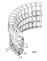
- FIG. 1 shows a circular heater for preforms 1, which are moved in the course of heating in accordance with the circumference of the heating device in a circular path.
- the heating device has a support 4, which simultaneously represents a rectangular waveguide. Attached to this carrier 4 are various assemblies, such as eight microwave compact heads 20 and forty microwave heating units 3. These units mounted on the carrier 4 rotate together about the machine axis 5. The transfer from an upstream unit to the oven 40 by means of a star, such as. B. a sawtooth or a staple star.
- a star such as. B. a sawtooth or a staple star.
- FIG. 2 shows a section of the oven 40 according to FIG. 1 , in which case the microwave heating unit 3 can be better explained.
- the microwaves compacting heads 20 that produce the microwaves are to be seen, which are connected directly to the carrier 4, which here represents a waveguide 22.
- the carrier 4 which here represents a waveguide 22.
- a coupling element 8 is mounted, which couples the microwaves generated by microwave compact head 20 from the carrier 4 in the microwave heating unit 3.
- the microwave heating unit 3 consists of an S-shaped rectangular microwave microwave waveguide whose first end is fixed to the carrier 4 and at the second end of a resonator 11 is attached.
- the resonator 11 is a disk-shaped, plate-shaped, hollow element inside, in the middle of which a circular hole is present. The dimensions of the hole are chosen so that the respective preforms 1 to be heated can be passed without any problems, wherein the resonator 11 has a height which corresponds to only a part of the height of the preforms.
- the hollow resonator 11 is an extension of the microwave heating unit 3 and is - as the waveguide - flows through microwaves.
- a temperature sensor 24 is attached to the microwave heating unit 3, which measures the temperature of preforms 1 which enter or exit the resonator 11 or are led out of it.
- a microwave tuner 23 is attached to the microwave heating unit 3, by means of which, by changing the conductor space of the microwave heating unit 3, it is possible to influence the microwaves - i. to optimize the field strength distribution with imported preform so that the reflected and not absorbed by the preform 1 amount of energy is minimized - and thus also to control the heating process of the preforms 1 and.
- the pickup unit 25 consists of a preform holding unit 26 and a moving unit 27 (for the preforms).
- the preform holding unit 26 is a mandrel which penetrates into the mouth of the preform 1 and thus holds it.
- at least a part of the preform holding unit is to be manufactured from a suitable non-metallic material, since otherwise leakage radiation may escape from the cavity.
- Preferred materials are plastics with low dielectric loss factor, such as Teflon.
- the movement unit 27 is preferably a multifunctional drive, wherein either different drives are fused to the movement unit 27, or wherein the movement unit 27 is formed by a drive which fulfills all movement requirements.
- a lowering movement is required, which introduces the preform 1 along its longitudinal axis A from above into the resonator 11.
- a lifting movement is required, which leads out the preform 1 along its longitudinal axis again from the resonator 11.
- Another movement that makes the heating process enormously more flexible is a rotational movement that causes the preform 1 to rotate about its longitudinal axis A.
- FIG. 3 has another embodiment of the heating unit for preforms 1.
- each microwave heating unit 3 has its own Microwave compact head 20 is assigned.
- the microwave heating unit 3 which is also formed here again as rectangular microwave waveguide is bent radially outwardly c-shaped. The one end opens in the microwave compact head 20, while at the other end again a resonator 11 is attached.
- the microwave heating unit 3 again has a microwave tuner 23, which performs the same task as in accordance with FIG. 2 ,
- the preform 1 is held by a receiving unit 25 comprising a preform holding unit 26 and a moving unit 27.
- FIG. 4 shows a section through the microwave compact head 20.
- a microwave generator 21 such.
- Example a magnetron or a klystron are generated by the microwaves and directed by a microwave conductor 22 to the circulator 29 and to the applicator 30.
- the microwave compact head 20 has two terminals 32, one terminal being the heating voltage plug-in terminal and the other terminal being the high-voltage terminal for the microwave generator 21.
- the circulator 29 is able to selectively transmit reflected radiation in the direction of the water load 28.
- the water load 28 is formed here by a U-shaped silicone tube, which is traversed by the cooling water.
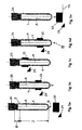
- FIG. 5 shows in five steps different positions of the preform 1 during its heating in the heating unit.
- the preform 1 has a region 2 to be heated, a region 10 which is not to be heated and a support ring 9 located in the region 10.
- the preform 1 is placed concentrically on a preform holding unit 26.
- movement unit 27 By in the Figures 2 and 3 described movement unit 27, it is now possible to move the preform 1 in the direction of the arrow 17 and 18 through the resonator 11.
- the black bar 33 represents the microwave influence region 23 of the resonator 11, not shown here.
- a first step according to FIG. 5a begun to move the preform 1 along its longitudinal axis A in the direction of the arrow 17 in the Mikrowellenein Let Scotland.
- FIG. 5B already shows a position in which the preform 1 has been moved a little way through the microwave influence region 33.
- FIG. 5C shows a position in which already the entire area to be heated of the preform 1 in the Microwave influence region 33 was or is. This is also the reversal point, after which an achievement of the preform 1 takes place from the microwave influence region 33 along the longitudinal axis A in the direction of the arrow 18.
- FIG. 5D shows a position that of FIG. 5B corresponds, in which case the preform 1 is moved along its longitudinal axis A in the direction of the arrow 18.
- an adaptation of the heating by means of microwaves is also carried out so that the setpoint temperature of the preform 1 can be exactly reached.
- the preform holding unit 26 may be provided with a hole, not shown here, through which, for example, a temperature sensor penetrates into the interior of the preform 1 to be heated, or through which certain media, for example, a cooling medium for temperature compensation can penetrate.
- FIG. 5E shows a position that the FIG. 5A corresponds, in which case the heating process is already completed.
- a second or third heating operation may also be performed by passing through the microwave influence region 33.
- FIG. 6 shows an apparatus for producing containers. This device has a preform storage 34 into which the preforms 1 are added unsorted.
- a roller sorter 35 takes over the separation and sorting of the preforms 1, which are then fed to a feed chute 36, which performs the supply to the oven 40.
- the preforms 1 are heated as described. After heating, a transfer takes place in the stretch blow molding machine 14, which produces finished containers. After the container is a transfer to the filling machine 15 and in a capper and / or a labeling machine not shown here. In this way, a completely filled and sealed container, such as e.g. a beverage bottle.
- a completely filled and sealed container such as e.g. a beverage bottle.
- at least two transport stars are preferably mounted, which effect an active and / or passive cooling of the heated preforms 1.
- a compensation or cooling time may also be necessary again after the stretch blow molding process.
- Active cooling may e.g. with water, air, nitrogen or other media from inside or outside.
- Passive cooling can be achieved by providing a transport path between the stretch blow molding machine 14 and the downstream machine.
- FIG. 7 shows a resonator 11, which has a hollow cylinder 11a at its top and bottom.
- This Hollow cylinder has the main effect of shielding microwaves.
- This protective device is cylindrical here, but it is within the scope of expert action to design this protective device in a different way, eg with an angular cross-section.
- a reflector element 19 In the area of effect of the microwave is located in the resonator 11, a reflector element 19.
- the object of this reflector element 19 is to heat the dome of the preform 1 in addition.
- the reflector element 19 is designed such that the microwave radiation is focused in the direction of the dome of the preform 1.
- the reflector element 19 is designed so that it always has the same distance to the tip of the preform 1 during the movement of the preform 1 through the resonator 11 at least in the effective range of the microwave. This can be accomplished, for example, by moving the reflector element 19 in the direction of the longitudinal axis A of the preform 1 through the resonator 11. It would also be conceivable that the reflector element is movable perpendicular to the longitudinal direction of the preform. But it is also conceivable that a plurality of reflector elements 19 are mounted in the effective range of the microwave, and these are conceivable in different heights. It is then possible in each case to pivot the reflector elements 19 laterally into the movement path of the preforms 1. The reflector element 19 is designed so that it is easily replaceable. This has the advantage that different preform geometries in the resonator 11 can each be optimally processed.
- FIG. 8 shows a preferred transfer situation of preforms 1 to the device and at the same time a takeover situation of preforms 1 from the resonator 11 before they are transported on to the next machine.
- the transport of the preforms 1 towards the resonator 11 and away from the resonator 11 is carried out here by grippers 50a, 50b.
- the grippers are preferably part of a transfer or acceptance starter, which are indicated here only schematically by the grippers 50a and 50b and the center column 37.
- the gripper 50a takes over a preform 1 from an upstream machine, e.g. a preform separating device and then passes this to a preform holding unit 26, which then performs the above-described treatment process by the parison 1 is guided at least once along its longitudinal axis A by the resonator 11.
- the preform When the preform exits after its treatment on the lower side of the resonator 11, it can be gripped by a gripper 50b operatively connected to the same center column 37 as the gripper 50a and fed to a downstream positioned machine, e.g. a labeling or filling machine to be handed over.
- a gripper 50b operatively connected to the same center column 37 as the gripper 50a and fed to a downstream positioned machine, e.g. a labeling or filling machine to be handed over.
- this arrangement has the advantage that a very large rotation angle can be used as a process time. With such an arrangement process angles between 300 ° and 355 ° can be achieved.
- this solution is very space-saving, since only one star transport is used as inlet and outlet star, while in conventional solutions two transport stars are installed.
- FIG. 9 shows an isometric view of another embodiment of a Mikrowellenermaschinerrnungsvorraum formed in Rund cramprbauweise.
- the device has a plurality of receiving units 25, wherein in each case a plurality of (at least two) receiving units 25 are attached to a receiving carrier 38.
- the recording media each have a movement unit 27, which is responsible for the lifting movement the preforms 1 in the direction of the resonators 11 is responsible.
- the preform holding units 26 have a drive for inducing a rotational movement in the preforms 1.
- the microwave heating device comprises a plurality of microwave compact heads 20, each consisting of a microwave tuner 23, a water load 28 and a microwave generator 21.
- the microwave conductor 22 is formed as a carrier 4 and has a flat disc shape, which is hollow inside, in order to be able to conduct the microwaves from the microwave generator 21 in the direction of the resonator 11.
- the microwave conductor 22 may be formed so that two disks are mounted on each other, which then form an inner cavity and thereby become the waveguide, but the conductor can also be constructed so that only segments are mounted on each other, so that no continuous circular disk pile is created but that each resonator 11 forms its demarcated waveguide 22.
- FIG. 10 shows a section through the microwave conductor 22 according to FIG. 9 , It can be seen that two waveguide segments 39 are mounted on one another in the resonator plane TE and thus form a microwave conductor 22.
- the two Holleitersegmente 39 are each constructed annularly.
- the resonators 11 are located with the respective hollow cylinders 11a arranged above and below them.
- the individual components are clearly visible.
- the microwave generator 21 and the circulator 29 and the water load 28 By the circulator, the microwaves from the generator 21 in the microwave waveguide 22 and there on the tuner 23 passed in the direction of the resonator 11.
- the tuner is formed so that three tuning pins 23a, 23b and 23c are immersed in the microwave conductor 22, thereby affecting the line cross section. In this way, an adaptation of the heating of the preforms 1 in the resonator 11 can be made. In this illustration, there is currently a preform 1 in the resonator 11.
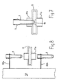
- Fig. 11 shows a further embodiment of a microwave conductor 22.
- the microwave conductor 22 is not constructed here of two ring or disc-shaped waveguide segments 39, but as a waveguide profile, of which a plurality of longitudinal pieces are joined together to form an entire waveguide.
- the microwave tuner 23 with its three pins 23a, 23b and 23c can be seen.
- a diaphragm 41 is provided which causes a diameter jump of the microwave conductor 22.
- a fastening element 42 is provided on which the diaphragm 41 is fastened.
- the fastener 42 has similar passage sizes as the aperture 41.
- the preforms 1 can be moved in a direction perpendicular to their longitudinal axis A in / through the resonator 11.
- the movement path of the preforms 1 projected into a resonator plane TE during the Heating essentially a circular path.
- each section 7 of the preforms 1 to be heated is also moved several times, but at least twice through the resonator 11.
- the plastic preforms and in particular PET preforms are formed by a blowing process, in particular a stretch blow molding process.
- preforms are exposed to both infrared and microwave radiation.
- the movement unit 27 for preforms 1 is preferably at least one lifting / lowering and at least one rotary drive. Furthermore, the preform holding unit 26 preferably comprises an outer and / or an inner gripper for preforms 1.
- each preform 1 is assigned a microwave heating unit 3 and a microwave compact head 20.
- a central microwave generator 21 is advantageously present, which is connected via microwave conductor 22 to the at least one microwave heating unit 3.
- the device includes n microwave generator 21 and m microwave heating units 3, where: m> n. More preferably, the device is designed as a machine rotating design.
- the device advantageously has at least two parallel planes in which preforms 1 can be heated.
- the device for heating preforms 1 described above is made of plastic, in particular for preforms 1 made of PET.
- the device is integrated in a machine arrangement, which further contains at least one stretch blow molding machine 14, wherein particularly preferably the stretch blow molding machine 14 is a rotary stretch blow molding machine.
- an infrared heating device is particularly preferably present before and / or after the oven 40.
- 40 infrared heating devices are present at the periphery of the furnace.
- the present invention is, as mentioned above, further directed to an arrangement for producing containers, at least consisting of a device for heating preforms 1 of the type described above, and a stretch blow molding machine 14. Preferably between the device for heating preforms 1 and the stretch blow molding machine 14 attached devices for active and / or passive cooling. Furthermore, the arrangement has at least one filling machine 15 and a closing machine 16.
Landscapes
- Physics & Mathematics (AREA)
- Engineering & Computer Science (AREA)
- Mechanical Engineering (AREA)
- Thermal Sciences (AREA)
- Manufacturing & Machinery (AREA)
- Electromagnetism (AREA)
- Blow-Moulding Or Thermoforming Of Plastics Or The Like (AREA)
- Processing And Handling Of Plastics And Other Materials For Molding In General (AREA)
- Constitution Of High-Frequency Heating (AREA)
Claims (14)
- Procédé de chauffage de préformes (1) en matière thermoplastique, présentant une zone à chauffer (2) et une zone à ne pas chauffer (6), les préformes (1) étant soumises à un processus de formage après leur chauffage, la zone à chauffer (2) des préformes (1) étant alimentée à des micro-ondes dans un résonateur (11) au moins pendant une partie de la durée du chauffage, caracterisée en ce qu'une cavité du résonateur est utilisée pour le chauffage des préformes, où la zone des préformes à chauffer est entièrement introduite, et en ce que la cavité du résonateur se déplace sur une trajectoire sensiblement circulaire.
- Procédé selon la revendication 1, caractérisé en ce que chaque préforme (1) est chauffée dans une cavité entourant complètement sa zone à chauffer (2).
- Procédé selon la revendication 1, caractérisé en ce que les préformes sont déplacées dans la direction de leur axe longitudinal (A) dans / par un résonateur (11) sensiblement en forme de disque ou de plateau respectivement, lequel entoure complètement les préformes (1).
- Procédé selon la revendication 1, caractérisé en ce que, projetée sur un plan de résonateur (TE), la trajectoire de déplacement des préformes (1) pendant le chauffage est sensiblement circulaire.
- Procédé selon la revendication 1, caractérisé en ce que les préformes (1) sont guidées dans le résonateur (11) au cours d'un déplacement sur une trajectoire sensiblement circulaire dans la direction de leur axe longitudinal (A), pour être ensuite ressorties du résonateur (11) dans la direction opposée.
- Procédé selon la revendication 1, caractérisé en ce que les préformes (1) tournent au moins partiellement autour de leur axe longitudinal (A).
- Procédé selon la revendication 1, caractérisé en ce que les préformes (1) sont tournées irrégulièrement autour de leur axe longitudinal (A) pendant le chauffage.
- Procédé selon la revendication 1, caractérisé en ce que la longueur et / ou l'épaisseur des préformes (1) sont chauffées de manière non homogène.
- Procédé selon la revendication 1, caractérisé en ce que la circonférence des préformes (1) est chauffée de manière non homogène.
- Procédé selon la revendication 1, caractérisé en ce que les préformes sont exposés à un rayonnement infrarouge ainsi qu'à un rayonnement micro-ondes.
- Procédé selon la revendication 1, caractérisé en ce qu'une répartition anisotrope d'intensité de champ est générée dans le résonateur (11) ou dans la cavité.
- Installation pour l'exécution du procédé selon l'une des revendications 1 à 11, pour le chauffage de préformes (1) au moyen de micro-ondes, comprenant au moins un générateur de micro-ondes (21), un microguide d'ondes (22) et un résonateur (11), le résonateur (11) comportant une cavité de résonateur où la zone des préformes (1) à chauffer est entièrement introduite, et l'installation étant réalisée comme machine de type rotatif,
une unité de chauffage par micro-ondes (3) étant associée à chaque préforme (1). - Installation selon la revendication 12, caractérisée en ce que le résonateur (11) est sensiblement en forme d'anneau, une ouverture étant prévue, par laquelle peut passer une préforme (1).
- Installation selon au moins la revendication 12, caractérisée en ce qu'elle est intégrée à un agencement de machines qui comporte en outre au moins une machine d'étirage-soufflage (14).
Applications Claiming Priority (2)
| Application Number | Priority Date | Filing Date | Title |
|---|---|---|---|
| DE102006022207 | 2006-05-11 | ||
| EP07725075.1A EP2021161B1 (fr) | 2006-05-11 | 2007-05-10 | Procédé de chauffe par micro-ondes d'ébauches en plastique |
Related Parent Applications (3)
| Application Number | Title | Priority Date | Filing Date |
|---|---|---|---|
| EP07725075.1A Division EP2021161B1 (fr) | 2006-05-11 | 2007-05-10 | Procédé de chauffe par micro-ondes d'ébauches en plastique |
| EP07725075.1A Division-Into EP2021161B1 (fr) | 2006-05-11 | 2007-05-10 | Procédé de chauffe par micro-ondes d'ébauches en plastique |
| EP07725075.1 Division | 2007-05-10 |
Publications (3)
| Publication Number | Publication Date |
|---|---|
| EP2213435A2 EP2213435A2 (fr) | 2010-08-04 |
| EP2213435A3 EP2213435A3 (fr) | 2012-08-22 |
| EP2213435B1 true EP2213435B1 (fr) | 2014-09-10 |
Family
ID=38442183
Family Applications (9)
| Application Number | Title | Priority Date | Filing Date |
|---|---|---|---|
| EP10160130.0A Active EP2210728B1 (fr) | 2006-05-11 | 2007-05-10 | Procédé et dispositif pour chauffer des ébauches en plastique |
| EP15164794.8A Active EP2937204B1 (fr) | 2006-05-11 | 2007-05-10 | Procede et dispositif de chauffage des ébauches en plastique avec des micro-ondes |
| EP16166840.5A Ceased EP3098057A3 (fr) | 2006-05-11 | 2007-05-10 | Procédé de chauffage et dispositif de chauffage pour ébauches en plastique |
| EP07725075.1A Not-in-force EP2021161B1 (fr) | 2006-05-11 | 2007-05-10 | Procédé de chauffe par micro-ondes d'ébauches en plastique |
| EP15164845.8A Not-in-force EP2939816B1 (fr) | 2006-05-11 | 2007-05-10 | Dispositif de chauffage par micro-ondes pour ébauches en plastique |
| EP10160125A Withdrawn EP2213434A3 (fr) | 2006-05-11 | 2007-05-10 | Dispositif de chauffage pour ébauches en plastique |
| EP10160127.6A Active EP2210731B1 (fr) | 2006-05-11 | 2007-05-10 | Dispositif de chauffe par micro-ondes d'ébauches en plastique et procédé de chauffe par micro-ondes d'ébauches en plastique |
| EP10160126.8A Not-in-force EP2213435B1 (fr) | 2006-05-11 | 2007-05-10 | Dispositif de chauffage pour ébauches en plastique |
| EP10160129.2A Active EP2258535B1 (fr) | 2006-05-11 | 2007-05-10 | Dispositif de chauffage pour ébauches en plastique |
Family Applications Before (7)
| Application Number | Title | Priority Date | Filing Date |
|---|---|---|---|
| EP10160130.0A Active EP2210728B1 (fr) | 2006-05-11 | 2007-05-10 | Procédé et dispositif pour chauffer des ébauches en plastique |
| EP15164794.8A Active EP2937204B1 (fr) | 2006-05-11 | 2007-05-10 | Procede et dispositif de chauffage des ébauches en plastique avec des micro-ondes |
| EP16166840.5A Ceased EP3098057A3 (fr) | 2006-05-11 | 2007-05-10 | Procédé de chauffage et dispositif de chauffage pour ébauches en plastique |
| EP07725075.1A Not-in-force EP2021161B1 (fr) | 2006-05-11 | 2007-05-10 | Procédé de chauffe par micro-ondes d'ébauches en plastique |
| EP15164845.8A Not-in-force EP2939816B1 (fr) | 2006-05-11 | 2007-05-10 | Dispositif de chauffage par micro-ondes pour ébauches en plastique |
| EP10160125A Withdrawn EP2213434A3 (fr) | 2006-05-11 | 2007-05-10 | Dispositif de chauffage pour ébauches en plastique |
| EP10160127.6A Active EP2210731B1 (fr) | 2006-05-11 | 2007-05-10 | Dispositif de chauffe par micro-ondes d'ébauches en plastique et procédé de chauffe par micro-ondes d'ébauches en plastique |
Family Applications After (1)
| Application Number | Title | Priority Date | Filing Date |
|---|---|---|---|
| EP10160129.2A Active EP2258535B1 (fr) | 2006-05-11 | 2007-05-10 | Dispositif de chauffage pour ébauches en plastique |
Country Status (7)
| Country | Link |
|---|---|
| US (1) | US8231823B2 (fr) |
| EP (9) | EP2210728B1 (fr) |
| JP (2) | JP5227949B2 (fr) |
| CN (1) | CN101454142B (fr) |
| AU (1) | AU2007251881B2 (fr) |
| CA (1) | CA2652020C (fr) |
| WO (1) | WO2007131701A2 (fr) |
Families Citing this family (43)
| Publication number | Priority date | Publication date | Assignee | Title |
|---|---|---|---|---|
| EP2210728B1 (fr) | 2006-05-11 | 2015-08-26 | Krones AG | Procédé et dispositif pour chauffer des ébauches en plastique |
| DE102009037172A1 (de) | 2008-02-11 | 2011-02-17 | Krones Ag | Behältnis - Behandlungsanlage mit rückwirkender Korrekturmöglichkeit |
| DE102008014215A1 (de) * | 2008-03-13 | 2009-09-17 | Krones Ag | Vorrichtung zum Erwärmen von Behältnissen |
| DE102008024108A1 (de) * | 2008-05-17 | 2009-11-19 | Krones Ag | Vorrichtung und Verfahren zum gesteuerten Erwärmen von Kunststoffbehältnissen |
| DE102008056346A1 (de) * | 2008-11-07 | 2010-05-12 | Krones Ag | Verfahren zur Vorbehandlung von Vorformlingen und Streckblasmaschine zur Vorbehandlung und zum Streckblasen von Vorformlingen zu Behältern |
| DE102008057403A1 (de) * | 2008-11-14 | 2010-05-20 | Krones Ag | Vorrichtung und Verfahren zum Herstellen von Kunststoffbehältnissen |
| DE102008060572A1 (de) * | 2008-12-04 | 2010-06-10 | Krones Ag | Vorrichtung zum Erwärmen von Kunststoffbehältnissen und Resonator hierfür |
| DE102009005358A1 (de) * | 2009-01-16 | 2010-07-22 | Krones Ag | Resonatoreinheit, Expansionsverfahren und Vorrichtung zur Erwärmung von Behältnissen |
| DE102009015519A1 (de) * | 2009-04-02 | 2010-10-07 | Krones Ag | Vorrichtung zum Umformen von Kunststoffvorformlingen mit Heizeinrichtung |
| DE102009025839A1 (de) * | 2009-05-19 | 2010-11-25 | Krones Ag | Verfahren und Temperiervorrichtung zur Erwärmung von Vorformlingen vor deren Umformung zu Behältern |
| DE102009035868A1 (de) * | 2009-07-31 | 2011-02-03 | Krones Ag | Vorrichtung zum Umformen von Kunststoffvorformlingen mit synchroner Erwärmung und Reckung |
| DE102009037200A1 (de) * | 2009-08-12 | 2011-02-17 | Krones Ag | Vorrichtung zum Zuführen von Preforms |
| DE202009019170U1 (de) * | 2009-09-07 | 2017-07-07 | Krones Ag | Vorrichtung zum Herstellen von Kunstoffflaschen |
| DE102009040559A1 (de) * | 2009-09-08 | 2011-03-10 | Krones Ag | Verfahren und Vorrichtung zum Blasformen von Behältern |
| DE102009047536A1 (de) * | 2009-12-04 | 2011-06-09 | Krones Ag | Ofen zum Konditionieren von Vorformlingen |
| DE102010011799A1 (de) * | 2010-03-17 | 2011-09-22 | Medi Gmbh & Co. Kg | Erwärmungsvorrichtung für einen thermoplastischen Prothesenschaftrohling |
| DE102010022131A1 (de) | 2010-05-20 | 2011-11-24 | Krones Ag | Sterilisierbare Blasform |
| DE102010021445A1 (de) * | 2010-05-25 | 2011-12-01 | Krones Ag | Verfahren und Vorrichtung zur Temperatursteuerung und/oder -regelung einer Heizvorrichtung für Vorformlinge |
| DE102010021446A1 (de) * | 2010-05-25 | 2011-12-01 | Krones Ag | Verfahren und Vorrichtung zur Temperierung von Vorformlingen |
| DE102010047223A1 (de) * | 2010-10-04 | 2012-04-05 | Krones Aktiengesellschaft | Vorrichtung und Verfahren zum Erwärmen von Kunststoffvorformlingen |
| DE102010047914A1 (de) * | 2010-10-11 | 2012-04-12 | Krones Aktiengesellschaft | Vorrichtung und Verfahren zum Erwärmen von Kunststoffvorformlingen |
| JP5563095B2 (ja) | 2010-10-25 | 2014-07-30 | 日精エー・エス・ビー機械株式会社 | 射出延伸ブロー成形装置 |
| EP2447172A1 (fr) * | 2010-11-02 | 2012-05-02 | Stefano Boido | Dispositif pour chauffer des récipients |
| FR2976514B1 (fr) * | 2011-06-17 | 2013-07-12 | Sidel Participations | Procede de chauffe d'ebauches de recipients |
| KR101290570B1 (ko) * | 2012-03-06 | 2013-07-31 | 삼성코닝정밀소재 주식회사 | 고주파 가열 장치 |
| ITPR20120020A1 (it) * | 2012-04-06 | 2013-10-07 | Gea Procomac Spa | Dispositivo e metodo per il riscaldamento di una preforma in materiale plastico |
| DE102012112370A1 (de) * | 2012-12-17 | 2014-06-18 | Krones Ag | Vorrichtung zum Erwärmen von Kunststoffvorformlingen |
| DE102013100627A1 (de) | 2013-01-22 | 2014-07-24 | Krones Aktiengesellschaft | Verfahren zum betreiben einer behälterbehandlungsanlage und behälterbehandlungsanlage |
| DE102013111528A1 (de) | 2013-10-18 | 2015-04-23 | Krones Ag | Vorrichtung und Verfahren zum Erwärmen von Kunststoffvorformlingen mit motorisch gesteuerten Halteelementen für die Kunststoffvorformlinge |
| FR3017325B1 (fr) | 2014-02-13 | 2016-04-22 | Sidel Participations | Installation de conditionnement thermique de preformes avec refroidissement d'une portion de la preforme par une lame d'air pulse |
| FR3031928A1 (fr) * | 2015-01-28 | 2016-07-29 | Sidel Participations | Installation de formage comportant un dispositif de mesure dont au moins une partie est montee conjointement en deplacement avec un organe de maintien d'un corps creux |
| DE102015101769A1 (de) | 2015-02-06 | 2016-08-11 | Krones Ag | Verfahren zum Kalibrieren zumindest eines Behandlungselementes |
| DE102015105925A1 (de) * | 2015-04-17 | 2016-10-20 | Krones Ag | Vorrichtung zum Erwärmen von Kunststoffvorformlingen mittels Mikrowellen |
| DE102015106744A1 (de) * | 2015-04-30 | 2016-11-03 | Krones Ag | Vorrichtung und Verfahren zum Erwärmen von Kunststoffvorformlingen mittels Mikrowellen mit anpassbarem Bodenreflektor |
| FR3037851B1 (fr) * | 2015-06-26 | 2017-07-07 | Sidel Participations | Procede de conditionnement thermique de preformes par micro-ondes avec detection de conformite des preformes |
| FR3037850B1 (fr) | 2015-06-26 | 2018-01-19 | Sidel Participations | Procede de chauffe hybride infrarouge et micro-ondes d'ebauches de recipients |
| DE102015112590A1 (de) * | 2015-07-31 | 2017-02-02 | Krones Ag | Verfahren und Vorrichtung zum Erwärmen von Kunststoffvorformlingen mit Abstimmung bei geringerer Leistung |
| US10071521B2 (en) | 2015-12-22 | 2018-09-11 | Mks Instruments, Inc. | Method and apparatus for processing dielectric materials using microwave energy |
| JP6619681B2 (ja) * | 2016-03-31 | 2019-12-11 | 株式会社吉野工業所 | ブロー成形方法 |
| IT201700019857A1 (it) * | 2017-02-22 | 2018-08-22 | Smi Spa | Sistema di movimentazione di contenitori tra unita' operative |
| EP3769935B1 (fr) * | 2019-07-22 | 2021-09-15 | SMI S.p.A. | Système de chauffage d'une préforme |
| CN111773762B (zh) * | 2020-06-09 | 2022-03-08 | 江苏恒科新材料有限公司 | 一种节能紧凑型聚酯切片结晶干燥系统 |
| CN117098644A (zh) * | 2021-03-03 | 2023-11-21 | 赫斯基注塑系统有限公司 | 塑料坯料加热方法和装置 |
Family Cites Families (24)
| Publication number | Priority date | Publication date | Assignee | Title |
|---|---|---|---|---|
| US3830893A (en) * | 1972-04-25 | 1974-08-20 | Monsanto Co | Method of processing high nitrile preforms |
| GB1380447A (en) * | 1971-04-29 | 1975-01-15 | Monsanto Co | Method of heating |
| JPS5333986B2 (fr) * | 1972-09-28 | 1978-09-18 | ||
| US4144434A (en) | 1976-06-14 | 1979-03-13 | Societe Lignes Telegraphiques Et Telephoniques | Microwave heating devices |
| JPS546370U (fr) * | 1977-06-14 | 1979-01-17 | ||
| US4156806A (en) | 1977-12-30 | 1979-05-29 | Raytheon Company | Concentrated energy microwave appliance |
| US4342895A (en) * | 1979-11-27 | 1982-08-03 | The Continental Group, Inc. | Method of processing polyethylene terephthalate preforms and apparatus |
| US4407651A (en) * | 1982-02-05 | 1983-10-04 | The Continental Group, Inc. | Hybrid reheating system and method for polymer preforms |
| JPS60179223A (ja) * | 1984-02-27 | 1985-09-13 | Toyobo Co Ltd | マイクロ波加熱延伸/熱処理装置 |
| JPH0622874B2 (ja) * | 1987-06-10 | 1994-03-30 | 東洋製罐株式会社 | 高分子樹脂成型品の加熱方法 |
| JP2591242Y2 (ja) * | 1992-07-30 | 1999-03-03 | 新日本無線株式会社 | マイクロ波加熱装置 |
| AR002773A1 (es) * | 1995-07-07 | 1998-04-29 | Continental Pet Technologies | Metodo para el moldeado por inyeccion de un articulo plastico y aparato para llevarlo a cabo. |
| JP4126090B2 (ja) * | 1996-04-19 | 2008-07-30 | 株式会社吉野工業所 | プリフォームの口頸部を結晶化する方法 |
| JP3758233B2 (ja) * | 1996-05-07 | 2006-03-22 | 東洋製罐株式会社 | 熱可塑性樹脂成形品の加熱方法と装置 |
| JPH11235751A (ja) * | 1998-02-20 | 1999-08-31 | Ueno Hiroshi | プラスチック成形体の結晶化方法 |
| JP4134473B2 (ja) * | 2000-01-11 | 2008-08-20 | 松下電器産業株式会社 | 高周波加熱装置 |
| DE10153045A1 (de) * | 2001-10-26 | 2003-05-08 | Sig Corpoplast Gmbh & Co Kg | Verfahren und Vorrichtung zur Steuerung eines Blasvorganges |
| WO2003055665A1 (fr) | 2001-12-13 | 2003-07-10 | Sig Corpoplast Gmbh & Co. Kg | Procede et dispositif d'equilibrage de temperature de preformes |
| US20030171889A1 (en) * | 2002-03-04 | 2003-09-11 | Shelby Marcus David | Method and device for predicting temperature profiles throughout the thickness of a polymer preform |
| US6979420B2 (en) * | 2002-03-28 | 2005-12-27 | Scimed Life Systems, Inc. | Method of molding balloon catheters employing microwave energy |
| US7163655B2 (en) | 2002-03-28 | 2007-01-16 | Scimed Life Systems, Inc. | Method and apparatus for extruding polymers employing microwave energy |
| DE102004037937B4 (de) * | 2004-08-04 | 2007-05-24 | Dorma Gmbh + Co. Kg | Türschloss, insbesondere mit Panikfunktion |
| EP1868785A1 (fr) * | 2005-04-07 | 2007-12-26 | SIG Technology Ltd. | Procede et dispositif servant a equilibrer la temperature de preformes |
| EP2210728B1 (fr) | 2006-05-11 | 2015-08-26 | Krones AG | Procédé et dispositif pour chauffer des ébauches en plastique |
-
2007
- 2007-05-10 EP EP10160130.0A patent/EP2210728B1/fr active Active
- 2007-05-10 EP EP15164794.8A patent/EP2937204B1/fr active Active
- 2007-05-10 EP EP16166840.5A patent/EP3098057A3/fr not_active Ceased
- 2007-05-10 JP JP2009508252A patent/JP5227949B2/ja active Active
- 2007-05-10 CN CN2007800177349A patent/CN101454142B/zh active Active
- 2007-05-10 EP EP07725075.1A patent/EP2021161B1/fr not_active Not-in-force
- 2007-05-10 WO PCT/EP2007/004154 patent/WO2007131701A2/fr active Application Filing
- 2007-05-10 EP EP15164845.8A patent/EP2939816B1/fr not_active Not-in-force
- 2007-05-10 CA CA2652020A patent/CA2652020C/fr not_active Expired - Fee Related
- 2007-05-10 EP EP10160125A patent/EP2213434A3/fr not_active Withdrawn
- 2007-05-10 US US12/300,589 patent/US8231823B2/en active Active
- 2007-05-10 AU AU2007251881A patent/AU2007251881B2/en not_active Ceased
- 2007-05-10 EP EP10160127.6A patent/EP2210731B1/fr active Active
- 2007-05-10 EP EP10160126.8A patent/EP2213435B1/fr not_active Not-in-force
- 2007-05-10 EP EP10160129.2A patent/EP2258535B1/fr active Active
-
2012
- 2012-09-18 JP JP2012204473A patent/JP5567085B2/ja active Active
Also Published As
Similar Documents
| Publication | Publication Date | Title |
|---|---|---|
| EP2213435B1 (fr) | Dispositif de chauffage pour ébauches en plastique | |
| DE102007022386A1 (de) | Erwärmungsvorrichtung für Kunststoffrohlinge | |
| DE4212248C2 (de) | Verfahren und Vorrichtung zur Erhitzung von, einem Vorrat entnommenen, im Spritzverfahren hergestellten Vorformlingen aus teilkristallinen Kunststoffen | |
| EP2428347B1 (fr) | Dispositif et procédé destinés à la fabrication de récipients ovales en matière plastique | |
| EP2208597B2 (fr) | Unité de résonateur, procédé d'expansion et dispositif de chauffage de récipients | |
| WO2016180510A1 (fr) | Procédé de thermorégulation non homogène de préformes | |
| DE2845407A1 (de) | Verfahren und vorrichtung zum nachwaermen von vorformlingen | |
| EP1868785A1 (fr) | Procede et dispositif servant a equilibrer la temperature de preformes | |
| EP2425959A1 (fr) | Dispositif et procédé de chauffage de préformes | |
| EP3423254A1 (fr) | Dispositif de chauffage et procédé pour le conditionnement thermique de préformes destinées au moulage par soufflage | |
| EP2799210A1 (fr) | Dispositif de chauffage et procédé de chauffage pour souffleuse ainsi que souffleuse | |
| EP3088162B1 (fr) | Dispositif et procede destines au chauffage d'ebauches en plastique a l'aide de micro-ondes ayant des reflecteurs de sol pouvant etre adaptes | |
| EP2439047A2 (fr) | Dispositif et procédé destinés au chauffage d'ébauches en plastique | |
| EP3679767A1 (fr) | Dispositif de chauffage de préformes en matière plastique avec un applicateur stationnaire | |
| DE202013012870U1 (de) | Ofen zum Erwärmen von Kunststoffvorformlingen mit Mehrfachumlauf der Kunststoffvorformlinge | |
| EP2628584B1 (fr) | Installation de transport et procédé de transport pour installation de traitement de récipients et souffleuse | |
| WO2003055665A1 (fr) | Procede et dispositif d'equilibrage de temperature de preformes | |
| WO2019048533A1 (fr) | Dispositif de chauffage de préformes en matière plastique, muni d'un applicateur fixe et d'un dispositif rotatif | |
| DE102017100613A1 (de) | Vorrichtung und Verfahren zum Erwärmen und Temperieren von Kunststoffvorformlingen | |
| DE102013105688B4 (de) | Ofen zum Erwärmen von Kunststoffvorformlingen mit Mehrfachumlauf der Kunststoffvorformlinge |
Legal Events
| Date | Code | Title | Description |
|---|---|---|---|
| PUAI | Public reference made under article 153(3) epc to a published international application that has entered the european phase |
Free format text: ORIGINAL CODE: 0009012 |
|
| AC | Divisional application: reference to earlier application |
Ref document number: 2021161 Country of ref document: EP Kind code of ref document: P |
|
| AK | Designated contracting states |
Kind code of ref document: A2 Designated state(s): AT BE BG CH CY CZ DE DK EE ES FI FR GB GR HU IE IS IT LI LT LU LV MC MT NL PL PT RO SE SI SK TR |
|
| RIN1 | Information on inventor provided before grant (corrected) |
Inventor name: SCHLOEGL, DR. MARTIN Inventor name: HUMELE, HEINZ Inventor name: FORSTHOEVEL, JOCHEN Inventor name: DETROIS, CHRISTIAN Inventor name: ZIMMERER, JOHANN |
|
| PUAL | Search report despatched |
Free format text: ORIGINAL CODE: 0009013 |
|
| AK | Designated contracting states |
Kind code of ref document: A3 Designated state(s): AT BE BG CH CY CZ DE DK EE ES FI FR GB GR HU IE IS IT LI LT LU LV MC MT NL PL PT RO SE SI SK TR |
|
| RIC1 | Information provided on ipc code assigned before grant |
Ipc: B29C 35/08 20060101ALI20120719BHEP Ipc: B29C 49/64 20060101AFI20120719BHEP |
|
| RIN1 | Information on inventor provided before grant (corrected) |
Inventor name: ZIMMERER, JOHANN Inventor name: FORSTHOEVEL, JOCHEN Inventor name: HUMELE, HEINZ Inventor name: SCHLOEGL, DR. MARTIN Inventor name: DETROIS, CHRISTIAN |
|
| 17P | Request for examination filed |
Effective date: 20130220 |
|
| 17Q | First examination report despatched |
Effective date: 20130905 |
|
| REG | Reference to a national code |
Ref country code: DE Ref legal event code: R079 Ref document number: 502007013457 Country of ref document: DE Free format text: PREVIOUS MAIN CLASS: B29B0013020000 Ipc: B29C0049640000 |
|
| GRAP | Despatch of communication of intention to grant a patent |
Free format text: ORIGINAL CODE: EPIDOSNIGR1 |
|
| INTG | Intention to grant announced |
Effective date: 20140320 |
|
| RIC1 | Information provided on ipc code assigned before grant |
Ipc: B29K 33/20 20060101ALI20140307BHEP Ipc: H05B 6/80 20060101ALI20140307BHEP Ipc: B29C 49/68 20060101ALI20140307BHEP Ipc: B29C 35/08 20060101ALI20140307BHEP Ipc: B29C 49/64 20060101AFI20140307BHEP Ipc: B29C 49/12 20060101ALI20140307BHEP |
|
| GRAS | Grant fee paid |
Free format text: ORIGINAL CODE: EPIDOSNIGR3 |
|
| GRAA | (expected) grant |
Free format text: ORIGINAL CODE: 0009210 |
|
| AC | Divisional application: reference to earlier application |
Ref document number: 2021161 Country of ref document: EP Kind code of ref document: P |
|
| AK | Designated contracting states |
Kind code of ref document: B1 Designated state(s): AT BE BG CH CY CZ DE DK EE ES FI FR GB GR HU IE IS IT LI LT LU LV MC MT NL PL PT RO SE SI SK TR |
|
| REG | Reference to a national code |
Ref country code: GB Ref legal event code: FG4D Free format text: NOT ENGLISH |
|
| REG | Reference to a national code |
Ref country code: CH Ref legal event code: EP |
|
| REG | Reference to a national code |
Ref country code: IE Ref legal event code: FG4D Free format text: LANGUAGE OF EP DOCUMENT: GERMAN |
|
| REG | Reference to a national code |
Ref country code: AT Ref legal event code: REF Ref document number: 686427 Country of ref document: AT Kind code of ref document: T Effective date: 20141015 |
|
| REG | Reference to a national code |
Ref country code: DE Ref legal event code: R096 Ref document number: 502007013457 Country of ref document: DE Effective date: 20141023 |
|
| PG25 | Lapsed in a contracting state [announced via postgrant information from national office to epo] |
Ref country code: FI Free format text: LAPSE BECAUSE OF FAILURE TO SUBMIT A TRANSLATION OF THE DESCRIPTION OR TO PAY THE FEE WITHIN THE PRESCRIBED TIME-LIMIT Effective date: 20140910 Ref country code: ES Free format text: LAPSE BECAUSE OF FAILURE TO SUBMIT A TRANSLATION OF THE DESCRIPTION OR TO PAY THE FEE WITHIN THE PRESCRIBED TIME-LIMIT Effective date: 20140910 Ref country code: SE Free format text: LAPSE BECAUSE OF FAILURE TO SUBMIT A TRANSLATION OF THE DESCRIPTION OR TO PAY THE FEE WITHIN THE PRESCRIBED TIME-LIMIT Effective date: 20140910 Ref country code: LT Free format text: LAPSE BECAUSE OF FAILURE TO SUBMIT A TRANSLATION OF THE DESCRIPTION OR TO PAY THE FEE WITHIN THE PRESCRIBED TIME-LIMIT Effective date: 20140910 Ref country code: GR Free format text: LAPSE BECAUSE OF FAILURE TO SUBMIT A TRANSLATION OF THE DESCRIPTION OR TO PAY THE FEE WITHIN THE PRESCRIBED TIME-LIMIT Effective date: 20141211 |
|
| REG | Reference to a national code |
Ref country code: NL Ref legal event code: VDEP Effective date: 20140910 |
|
| REG | Reference to a national code |
Ref country code: LT Ref legal event code: MG4D |
|
| PG25 | Lapsed in a contracting state [announced via postgrant information from national office to epo] |
Ref country code: CY Free format text: LAPSE BECAUSE OF FAILURE TO SUBMIT A TRANSLATION OF THE DESCRIPTION OR TO PAY THE FEE WITHIN THE PRESCRIBED TIME-LIMIT Effective date: 20140910 Ref country code: LV Free format text: LAPSE BECAUSE OF FAILURE TO SUBMIT A TRANSLATION OF THE DESCRIPTION OR TO PAY THE FEE WITHIN THE PRESCRIBED TIME-LIMIT Effective date: 20140910 |
|
| PG25 | Lapsed in a contracting state [announced via postgrant information from national office to epo] |
Ref country code: NL Free format text: LAPSE BECAUSE OF FAILURE TO SUBMIT A TRANSLATION OF THE DESCRIPTION OR TO PAY THE FEE WITHIN THE PRESCRIBED TIME-LIMIT Effective date: 20140910 |
|
| PG25 | Lapsed in a contracting state [announced via postgrant information from national office to epo] |
Ref country code: SK Free format text: LAPSE BECAUSE OF FAILURE TO SUBMIT A TRANSLATION OF THE DESCRIPTION OR TO PAY THE FEE WITHIN THE PRESCRIBED TIME-LIMIT Effective date: 20140910 Ref country code: PT Free format text: LAPSE BECAUSE OF FAILURE TO SUBMIT A TRANSLATION OF THE DESCRIPTION OR TO PAY THE FEE WITHIN THE PRESCRIBED TIME-LIMIT Effective date: 20150112 Ref country code: IS Free format text: LAPSE BECAUSE OF FAILURE TO SUBMIT A TRANSLATION OF THE DESCRIPTION OR TO PAY THE FEE WITHIN THE PRESCRIBED TIME-LIMIT Effective date: 20150110 Ref country code: EE Free format text: LAPSE BECAUSE OF FAILURE TO SUBMIT A TRANSLATION OF THE DESCRIPTION OR TO PAY THE FEE WITHIN THE PRESCRIBED TIME-LIMIT Effective date: 20140910 Ref country code: CZ Free format text: LAPSE BECAUSE OF FAILURE TO SUBMIT A TRANSLATION OF THE DESCRIPTION OR TO PAY THE FEE WITHIN THE PRESCRIBED TIME-LIMIT Effective date: 20140910 Ref country code: RO Free format text: LAPSE BECAUSE OF FAILURE TO SUBMIT A TRANSLATION OF THE DESCRIPTION OR TO PAY THE FEE WITHIN THE PRESCRIBED TIME-LIMIT Effective date: 20140910 |
|
| PG25 | Lapsed in a contracting state [announced via postgrant information from national office to epo] |
Ref country code: PL Free format text: LAPSE BECAUSE OF FAILURE TO SUBMIT A TRANSLATION OF THE DESCRIPTION OR TO PAY THE FEE WITHIN THE PRESCRIBED TIME-LIMIT Effective date: 20140910 |
|
| REG | Reference to a national code |
Ref country code: DE Ref legal event code: R026 Ref document number: 502007013457 Country of ref document: DE |
|
| PLBI | Opposition filed |
Free format text: ORIGINAL CODE: 0009260 |
|
| PLAX | Notice of opposition and request to file observation + time limit sent |
Free format text: ORIGINAL CODE: EPIDOSNOBS2 |
|
| 26 | Opposition filed |
Opponent name: GEA PROCOMAC S.P.A. Effective date: 20150609 |
|
| PG25 | Lapsed in a contracting state [announced via postgrant information from national office to epo] |
Ref country code: DK Free format text: LAPSE BECAUSE OF FAILURE TO SUBMIT A TRANSLATION OF THE DESCRIPTION OR TO PAY THE FEE WITHIN THE PRESCRIBED TIME-LIMIT Effective date: 20140910 |
|
| PLBB | Reply of patent proprietor to notice(s) of opposition received |
Free format text: ORIGINAL CODE: EPIDOSNOBS3 |
|
| PG25 | Lapsed in a contracting state [announced via postgrant information from national office to epo] |
Ref country code: SI Free format text: LAPSE BECAUSE OF FAILURE TO SUBMIT A TRANSLATION OF THE DESCRIPTION OR TO PAY THE FEE WITHIN THE PRESCRIBED TIME-LIMIT Effective date: 20140910 |
|
| REG | Reference to a national code |
Ref country code: CH Ref legal event code: PL |
|
| GBPC | Gb: european patent ceased through non-payment of renewal fee |
Effective date: 20150510 |
|
| PG25 | Lapsed in a contracting state [announced via postgrant information from national office to epo] |
Ref country code: MC Free format text: LAPSE BECAUSE OF FAILURE TO SUBMIT A TRANSLATION OF THE DESCRIPTION OR TO PAY THE FEE WITHIN THE PRESCRIBED TIME-LIMIT Effective date: 20140910 Ref country code: CH Free format text: LAPSE BECAUSE OF NON-PAYMENT OF DUE FEES Effective date: 20150531 Ref country code: LI Free format text: LAPSE BECAUSE OF NON-PAYMENT OF DUE FEES Effective date: 20150531 Ref country code: LU Free format text: LAPSE BECAUSE OF FAILURE TO SUBMIT A TRANSLATION OF THE DESCRIPTION OR TO PAY THE FEE WITHIN THE PRESCRIBED TIME-LIMIT Effective date: 20150510 |
|
| REG | Reference to a national code |
Ref country code: IE Ref legal event code: MM4A |
|
| REG | Reference to a national code |
Ref country code: FR Ref legal event code: PLFP Year of fee payment: 10 |
|
| PG25 | Lapsed in a contracting state [announced via postgrant information from national office to epo] |
Ref country code: IE Free format text: LAPSE BECAUSE OF NON-PAYMENT OF DUE FEES Effective date: 20150510 Ref country code: GB Free format text: LAPSE BECAUSE OF NON-PAYMENT OF DUE FEES Effective date: 20150510 |
|
| REG | Reference to a national code |
Ref country code: AT Ref legal event code: MM01 Ref document number: 686427 Country of ref document: AT Kind code of ref document: T Effective date: 20150510 |
|
| PG25 | Lapsed in a contracting state [announced via postgrant information from national office to epo] |
Ref country code: AT Free format text: LAPSE BECAUSE OF NON-PAYMENT OF DUE FEES Effective date: 20150510 |
|
| PLCK | Communication despatched that opposition was rejected |
Free format text: ORIGINAL CODE: EPIDOSNREJ1 |
|
| APBM | Appeal reference recorded |
Free format text: ORIGINAL CODE: EPIDOSNREFNO |
|
| APBP | Date of receipt of notice of appeal recorded |
Free format text: ORIGINAL CODE: EPIDOSNNOA2O |
|
| APAH | Appeal reference modified |
Free format text: ORIGINAL CODE: EPIDOSCREFNO |
|
| PG25 | Lapsed in a contracting state [announced via postgrant information from national office to epo] |
Ref country code: MT Free format text: LAPSE BECAUSE OF FAILURE TO SUBMIT A TRANSLATION OF THE DESCRIPTION OR TO PAY THE FEE WITHIN THE PRESCRIBED TIME-LIMIT Effective date: 20140910 |
|
| REG | Reference to a national code |
Ref country code: DE Ref legal event code: R100 Ref document number: 502007013457 Country of ref document: DE |
|
| APBU | Appeal procedure closed |
Free format text: ORIGINAL CODE: EPIDOSNNOA9O |
|
| PLBN | Opposition rejected |
Free format text: ORIGINAL CODE: 0009273 |
|
| STAA | Information on the status of an ep patent application or granted ep patent |
Free format text: STATUS: OPPOSITION REJECTED |
|
| 27O | Opposition rejected |
Effective date: 20170206 |
|
| REG | Reference to a national code |
Ref country code: FR Ref legal event code: PLFP Year of fee payment: 11 |
|
| PG25 | Lapsed in a contracting state [announced via postgrant information from national office to epo] |
Ref country code: BG Free format text: LAPSE BECAUSE OF FAILURE TO SUBMIT A TRANSLATION OF THE DESCRIPTION OR TO PAY THE FEE WITHIN THE PRESCRIBED TIME-LIMIT Effective date: 20140910 Ref country code: HU Free format text: LAPSE BECAUSE OF FAILURE TO SUBMIT A TRANSLATION OF THE DESCRIPTION OR TO PAY THE FEE WITHIN THE PRESCRIBED TIME-LIMIT; INVALID AB INITIO Effective date: 20070510 |
|
| PG25 | Lapsed in a contracting state [announced via postgrant information from national office to epo] |
Ref country code: BE Free format text: LAPSE BECAUSE OF NON-PAYMENT OF DUE FEES Effective date: 20150531 |
|
| PG25 | Lapsed in a contracting state [announced via postgrant information from national office to epo] |
Ref country code: TR Free format text: LAPSE BECAUSE OF FAILURE TO SUBMIT A TRANSLATION OF THE DESCRIPTION OR TO PAY THE FEE WITHIN THE PRESCRIBED TIME-LIMIT Effective date: 20140910 |
|
| REG | Reference to a national code |
Ref country code: FR Ref legal event code: PLFP Year of fee payment: 12 |
|
| PGFP | Annual fee paid to national office [announced via postgrant information from national office to epo] |
Ref country code: FR Payment date: 20210412 Year of fee payment: 15 Ref country code: IT Payment date: 20210412 Year of fee payment: 15 Ref country code: DE Payment date: 20210413 Year of fee payment: 15 |
|
| REG | Reference to a national code |
Ref country code: DE Ref legal event code: R119 Ref document number: 502007013457 Country of ref document: DE |
|
| PG25 | Lapsed in a contracting state [announced via postgrant information from national office to epo] |
Ref country code: FR Free format text: LAPSE BECAUSE OF NON-PAYMENT OF DUE FEES Effective date: 20220531 |
|
| PG25 | Lapsed in a contracting state [announced via postgrant information from national office to epo] |
Ref country code: DE Free format text: LAPSE BECAUSE OF NON-PAYMENT OF DUE FEES Effective date: 20221201 |
|
| PG25 | Lapsed in a contracting state [announced via postgrant information from national office to epo] |
Ref country code: IT Free format text: LAPSE BECAUSE OF NON-PAYMENT OF DUE FEES Effective date: 20220510 |