EP2212731B1 - Image sensing apparatus - Google Patents
Image sensing apparatus Download PDFInfo
- Publication number
- EP2212731B1 EP2212731B1 EP08841526.0A EP08841526A EP2212731B1 EP 2212731 B1 EP2212731 B1 EP 2212731B1 EP 08841526 A EP08841526 A EP 08841526A EP 2212731 B1 EP2212731 B1 EP 2212731B1
- Authority
- EP
- European Patent Office
- Prior art keywords
- image
- image sensor
- mode
- pixels
- lines
- Prior art date
- Legal status (The legal status is an assumption and is not a legal conclusion. Google has not performed a legal analysis and makes no representation as to the accuracy of the status listed.)
- Active
Links
- 238000001514 detection method Methods 0.000 claims description 18
- 230000003287 optical effect Effects 0.000 claims description 3
- 210000001747 pupil Anatomy 0.000 claims description 3
- 238000000034 method Methods 0.000 description 59
- 230000008569 process Effects 0.000 description 44
- 238000006243 chemical reaction Methods 0.000 description 16
- 238000012545 processing Methods 0.000 description 5
- 238000010586 diagram Methods 0.000 description 3
- 238000012937 correction Methods 0.000 description 2
- 238000005286 illumination Methods 0.000 description 2
- 238000003384 imaging method Methods 0.000 description 2
- 238000013459 approach Methods 0.000 description 1
- 230000008901 benefit Effects 0.000 description 1
- 230000015572 biosynthetic process Effects 0.000 description 1
- 230000008859 change Effects 0.000 description 1
- 230000006835 compression Effects 0.000 description 1
- 238000007906 compression Methods 0.000 description 1
- 239000000284 extract Substances 0.000 description 1
- 230000004907 flux Effects 0.000 description 1
- 230000006870 function Effects 0.000 description 1
- 230000007274 generation of a signal involved in cell-cell signaling Effects 0.000 description 1
- 239000004973 liquid crystal related substance Substances 0.000 description 1
- 239000011159 matrix material Substances 0.000 description 1
- 238000005259 measurement Methods 0.000 description 1
- 238000012986 modification Methods 0.000 description 1
- 230000004048 modification Effects 0.000 description 1
- 230000010363 phase shift Effects 0.000 description 1
- 229910052709 silver Inorganic materials 0.000 description 1
- 239000004332 silver Substances 0.000 description 1
- -1 silver halide Chemical class 0.000 description 1
- 239000007787 solid Substances 0.000 description 1
- 230000009466 transformation Effects 0.000 description 1
Images


Classifications
-
- G—PHYSICS
- G02—OPTICS
- G02B—OPTICAL ELEMENTS, SYSTEMS OR APPARATUS
- G02B7/00—Mountings, adjusting means, or light-tight connections, for optical elements
- G02B7/28—Systems for automatic generation of focusing signals
- G02B7/34—Systems for automatic generation of focusing signals using different areas in a pupil plane
-
- G—PHYSICS
- G02—OPTICS
- G02B—OPTICAL ELEMENTS, SYSTEMS OR APPARATUS
- G02B7/00—Mountings, adjusting means, or light-tight connections, for optical elements
- G02B7/28—Systems for automatic generation of focusing signals
- G02B7/36—Systems for automatic generation of focusing signals using image sharpness techniques, e.g. image processing techniques for generating autofocus signals
-
- G—PHYSICS
- G03—PHOTOGRAPHY; CINEMATOGRAPHY; ANALOGOUS TECHNIQUES USING WAVES OTHER THAN OPTICAL WAVES; ELECTROGRAPHY; HOLOGRAPHY
- G03B—APPARATUS OR ARRANGEMENTS FOR TAKING PHOTOGRAPHS OR FOR PROJECTING OR VIEWING THEM; APPARATUS OR ARRANGEMENTS EMPLOYING ANALOGOUS TECHNIQUES USING WAVES OTHER THAN OPTICAL WAVES; ACCESSORIES THEREFOR
- G03B13/00—Viewfinders; Focusing aids for cameras; Means for focusing for cameras; Autofocus systems for cameras
- G03B13/32—Means for focusing
- G03B13/34—Power focusing
- G03B13/36—Autofocus systems
-
- H—ELECTRICITY
- H04—ELECTRIC COMMUNICATION TECHNIQUE
- H04N—PICTORIAL COMMUNICATION, e.g. TELEVISION
- H04N23/00—Cameras or camera modules comprising electronic image sensors; Control thereof
- H04N23/60—Control of cameras or camera modules
- H04N23/63—Control of cameras or camera modules by using electronic viewfinders
-
- H—ELECTRICITY
- H04—ELECTRIC COMMUNICATION TECHNIQUE
- H04N—PICTORIAL COMMUNICATION, e.g. TELEVISION
- H04N23/00—Cameras or camera modules comprising electronic image sensors; Control thereof
- H04N23/60—Control of cameras or camera modules
- H04N23/67—Focus control based on electronic image sensor signals
- H04N23/672—Focus control based on electronic image sensor signals based on the phase difference signals
-
- H—ELECTRICITY
- H04—ELECTRIC COMMUNICATION TECHNIQUE
- H04N—PICTORIAL COMMUNICATION, e.g. TELEVISION
- H04N25/00—Circuitry of solid-state image sensors [SSIS]; Control thereof
- H04N25/70—SSIS architectures; Circuits associated therewith
- H04N25/703—SSIS architectures incorporating pixels for producing signals other than image signals
- H04N25/704—Pixels specially adapted for focusing, e.g. phase difference pixel sets
-
- H—ELECTRICITY
- H04—ELECTRIC COMMUNICATION TECHNIQUE
- H04N—PICTORIAL COMMUNICATION, e.g. TELEVISION
- H04N2101/00—Still video cameras
-
- H—ELECTRICITY
- H04—ELECTRIC COMMUNICATION TECHNIQUE
- H04N—PICTORIAL COMMUNICATION, e.g. TELEVISION
- H04N23/00—Cameras or camera modules comprising electronic image sensors; Control thereof
- H04N23/80—Camera processing pipelines; Components thereof
- H04N23/84—Camera processing pipelines; Components thereof for processing colour signals
- H04N23/843—Demosaicing, e.g. interpolating colour pixel values
-
- H—ELECTRICITY
- H04—ELECTRIC COMMUNICATION TECHNIQUE
- H04N—PICTORIAL COMMUNICATION, e.g. TELEVISION
- H04N25/00—Circuitry of solid-state image sensors [SSIS]; Control thereof
- H04N25/10—Circuitry of solid-state image sensors [SSIS]; Control thereof for transforming different wavelengths into image signals
- H04N25/11—Arrangement of colour filter arrays [CFA]; Filter mosaics
- H04N25/13—Arrangement of colour filter arrays [CFA]; Filter mosaics characterised by the spectral characteristics of the filter elements
- H04N25/134—Arrangement of colour filter arrays [CFA]; Filter mosaics characterised by the spectral characteristics of the filter elements based on three different wavelength filter elements
Definitions
- the present invention relates to an image sensing apparatus such as a digital still camera.
- the digital still camera using a high-pixel-density image sensor adopts a driving method as the operation mode of the image sensor during EVF display or moving image sensing.
- this driving method signal lines other than those necessary for display on a liquid-crystal display device are thinned out to increase the finder rate.
- a high-resolution digital still camera has been strongly required to sense a still image as instantaneously as a silver halide camera.
- the time from when the release switch is pressed until image sensing must be short sufficiently.
- AF requires only a short time until focusing
- a variety of inventions associated with the phase difference AF scheme have been proposed.
- Japanese Patent Laid-Open No. 2000-156823 discloses a technique associated with an AF scheme. This technique arranges photoelectric conversion elements for phase difference AF on the image sensor and uses a signal output from the image sensor in order to perform phase difference AF without any mechanical phase difference detection structure.
- Japanese Patent Laid-Open No. 2003-198925 discloses a technique of switching lines to be read out between the AF time and the image generation time when the lines of the image sensor are thinned out and read out in EVF display or moving image sensing in an image sensing apparatus in which the image sensor includes photoelectric conversion elements for phase difference AF.
- US 2007/237511 discloses an image sensor includes imaging a first focus detection pixel group and a second focus detection pixel group respectively made up with an array of first focus detection pixels and an array of second focus detection pixels, with the first focus detection pixels and the second focus detection pixels used to receive an image light flux via an optical system to detect a focus adjustment state at the optical system through a pupil division-type method.
- An image detection pitch of the first and second focus detection pixel groups is different from each other.
- US 2003/011693 discloses an image sensor and a digital camera capable of executing accurate image-shooting adjustment even in a low illumination environment.
- a charge coupled device type of image sensor includes red, green and blue pixel cells provided with color filter segments and control cells not provided with color filter segments.
- a digital signal processor When a controller determines that the illumination of a scene to be picked up is short, a digital signal processor generates estimated luminance and contrast values for automatic exposure and automatic focus controls in accordance with the outputs of the control cells.
- US2005/068455 discloses a solid state image pickup device, comprising a photoelectrical conversion element array and a pixel-data-reading-out control unit.
- the pixel-data-reading-out control unit controls execution of: a whole-pixel-reading-out mode for picking up still pictures, which outputs the read-out pixel data of the whole pixels in order by a data unit of a single pixel in order; a vertically/horizontally-mixed-pixel-reading-out mode for recording moving pictures, which outputs the pixel data after mixing a plurality of pixels in the vertical and horizontal directions of the photoelectrical conversion element array; and a one-directionally-mixed-pixel-reading-out mode for auto-focus, which, at the time of controlling the auto-focus, outputs pixel data mixed in only one direction by canceling mixing of pixel data for a plurality of pixels read out from the photoelectrical conversion element array in either the vertical direction or the horizontal direction of the array.
- an image sensing apparatus as claimed in claim 1 herein.
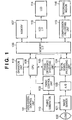
- Fig. 1 is a block diagram showing an image sensing apparatus according to the first preferred embodiment of the present invention.
- An object image which has entered the image sensing apparatus via a lens 100 is photoelectrically converted into an electrical signal by an image sensor 101.
- image sensing pixels R, G, and B for image data formation and focus detecting pixels S1 and S2 for phase difference AF are arrayed on the image sensor 101, as shown in Fig. 2 .
- This embodiment will exemplify an image sensor in which the focus detecting pixels S1 and S2 are paired and arranged and a different number of focus detecting pixels are arranged for each line, as shown in Fig. 2 .
- first lines in each of which N (N is an integer equal to or more than 2) focus detecting pixels are arranged, and second lines in each of which M (M is an integer greater than zero and less than N) focus detecting pixels are arranged are arranged periodically.
- lines (corresponding to the arrows of "EVF") in each of which two focus detecting pixels are arranged, and lines (corresponding to the arrows of "Moving Image") in each of which one focus detecting pixel is arranged are arranged periodically.
- An A/D conversion unit 103 converts the electrical signal output from the image sensor 101 into a digital signal.
- a digital signal processing unit 104 converts the digital signal output from the A/D conversion unit 103 into image data in the YUV data format.
- the A/D conversion unit 103 can comprise, e.g., a WB circuit, ⁇ correction circuit, and matrix transformation circuit.
- the digital signal processing unit 104 extracts AF data from the digital signal output from the A/D conversion unit 103, in accordance with the readout mode of the image sensor 101.
- a CPU 108 determines the positions of the focus detecting pixels S1 and S2 on the basis of the position pattern information of distance measurement cells that is recorded in a built-in ROM, and interpolates pixel signals corresponding to these positions with their surrounding pixels. For example, the pixels S1 shown in Fig. 2 need only be interpolated using pixel signals from their surrounding R pixels by, e.g., the known bicubic method. After that, the resultant image data is converted into image data in the YUV data format. Furthermore, processes such as ⁇ correction are performed for the image data in the YUV data format.
- a phase difference detecting unit 105 performs phase difference detection on the basis of the AF data output from the digital signal processing unit 104.
- the phase difference detection by the image sensor is described in detail in Japanese Patent Laid-Open No. 2000-156823 , and a detailed description thereof will not be given herein.
- an approximate image which assumes that the rows of the pixels S1 and S2 are nearly identical to each other is formed on a microlens. If the camera lens which focuses onto an image on the image sensor is in focus on the image sensor, an image signal from an S1 group in each row including the pixels S1 matches that from an S2 group in each row including the pixels S2.
- an image signal from an S1 group in each row including the pixels S1 is out of phase from that from an S2 group in each row including the pixels S2.
- the phase shift direction reverses depending on whether the imaging point lies at the front or rear side of the image plane.
- this scheme is the same as the pupil division phase difference AF in this point.
- an image formed in accordance with the array of the pixels S1 (a signal line which depends on the light intensity), and that formed in accordance with the array of the pixels S2 match each other if the camera lens is in focus, and they shift from each other if the camera lens is out of focus.
- the phase difference detection result obtained by the phase difference detecting unit 105 is sent to the CPU 108.
- the CPU 108 outputs a control signal to a lens barrel control unit 111 on the basis of the detection result sent from the phase difference detecting unit 105.
- An operation unit 112 includes, e.g., a button for switching the image sensing mode between still image sensing and moving image sensing, and setting switches such as a shutter switch.
- the CPU 108 sends a control signal to a timing control unit 109 in accordance with the image sensing mode set by the operation unit 112.
- a timing generator 110 serves as a driving signal generation means for generating an image data readout driving signal on the basis of the control signal from the timing control unit 109.
- a method of reading out data from the image sensor 101 changes upon switching the readout driving signal in accordance with the image sensing mode.
- the image data in the YUV data format output from the digital signal processing unit 104 is temporarily saved in a memory 107 via a memory I/F 106 as image data for EVF display.
- An LCD I/F 113 converts the image data in the YUV data format saved in the memory 107 into that in the display format of a readout LCD 114 via the memory I/F 106.
- the readout LCD 114 performs EVF display on the basis of the image data output from the LCD I/F 113.
- the image data in the YUV data format output from the digital signal processing unit 104 is compressed in accordance with a standard such as JPEG, and recorded on a recording medium 116 by a compression/recording unit 115 via the memory I/F 106.
- a standard such as JPEG
- a first readout mode of reading out all the lines is a still image mode.
- a second readout mode of reading out lines having a large number of focus detecting pixels is an EVF mode, as shown in Fig. 2 .
- a third readout mode of reading out lines having a small number of focus detecting pixels is a moving image mode.
- the process sequence starts and the image sensing mode is set to the still image sensing mode by the operation unit 112.
- the CPU 108 performs the following process unless otherwise specified.
- step S100 the timing generator 110 is set to the EVF mode. With this operation, lines having a large number of focus detecting pixels are read out from the image sensor 101.
- step S101 it is checked whether the shutter switch of the operation unit 112 is pressed halfway. If the shutter switch is not pressed halfway ("NO” in step S101), step S101 is repeated. If the shutter switch is pressed halfway ("YES” in step S101), the process advances to step S102.
- step S102 phase difference detection is performed using AF data extracted from the image data read out from the image sensor 101. Then, the lens position is moved by moving the lens barrel by the lens barrel control unit 111 so as to reduce the phase difference, thereby adjusting the focus.
- step S103 the state of the shutter switch is checked. If the shutter switch is kept pressed halfway, step S103 is repeated. If the shutter switch is released, the process returns to step S101. If the shutter switch is pressed fully, the process advances to step S104.
- step S104 the timing generator 110 is set to the still image mode.
- the still image mode a sensed image is read out from all the lines of the image sensor 101.
- step S105 the readout sensed image (still image) is captured and recorded on the recording medium 116.
- step S100 After that, the process sequence from step S100 is repeated until the power supply is turned off by the operation unit 112.
- the above-described process sequence can increase the AF accuracy for high resolution in the still image sensing according to this embodiment.
- autofocus and EVF display are performed by reading out lines having a large number of focus detecting pixels from the image sensor 101 during EVF display.
- recording a still image all the lines of the image sensor 101 are read out. This makes it possible to record a high-resolution image.
- the process sequence starts and the image sensing mode is set to the still image sensing mode by the operation unit 112.
- the CPU 108 performs the following process unless otherwise specified.
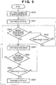
- step S200 the timing generator 110 is set to the moving image mode. With this operation, lines having a small number of focus detecting pixels are read out from the image sensor 101.
- step S201 autofocus is performed.
- phase difference detection is performed using AF data extracted from the image data read out from the image sensor 101, as in the still image sensing.
- the lens position is moved by moving the lens barrel by the lens barrel control unit 111 so as to reduce the phase difference, thereby adjusting the focus.
- step S202 it is checked whether the moving image sensing start button is pressed in the operation unit 112. If the moving image sensing start button is not pressed ("NO” in step S202), the process advances to step S203. If the moving image sensing start button is pressed ("YES” in step S202), the process advances to step S204.
- step S203 the timer value is compared with a preset value to check the time which has elapsed from the previous autofocus.
- Fig. 5 exemplifies a case in which the timer value is compared with 0.2 sec
- the present invention is not particularly limited to this. If 0.2 sec or more has elapsed already ("YES" in step S203), the process returns to step S201 and autofocus is performed again. If 0.2 sec or more has not elapsed yet ("NO" in step S203), step S202 is repeated.
- step S204 a moving image is captured and the image data is recorded on the recording medium 116.
- step S205 it is checked whether the moving image sensing end button is pressed in the operation unit 112. If the moving image sensing end button is pressed ("YES” in step S205), the process returns to step S202. If the moving image sensing end button is not pressed ("NO” in step S205), the process advances to step S206.
- step S206 it is checked whether a preset time (e.g., 0.2 sec in Fig. 5 ) or more has elapsed from the previous autofocus until the process shifts to step S206. If 0.2 sec or more has elapsed already ("YES" in step S206), the process advances to step S207 and autofocus is performed again. After that, the process returns to step S204, and a moving image is captured and the image data is recorded on the recording medium 116.
- a preset time e.g., 0.2 sec in Fig. 5
- step S206 If 0.2 sec or more has not elapsed yet ("NO" in step S206), autofocus is not performed.
- the process returns to step S204, and a moving image is captured and the image data is recorded on the recording medium 116. After that, the process sequence from step S200 is repeated until the power supply is turned off by the operation unit 112.
- lines having a small number of focus detecting pixels are read out from the image sensor 101 by the above-described process sequence in order to record a moving image with a quality better than that of the EVF image in the still image sensing. This makes it possible to record a moving image with a quality better than that of the EVF image.
- all the lines of the image sensor 101 include focus detecting pixels, as shown in Fig. 2 .
- the second embodiment provides third lines (corresponding to the arrows of "Recording/display") including no focus detecting pixels in an image sensor 101. The switching of the readout mode of an image sensor according to this embodiment will be explained below.
- a block diagram of an image sensing apparatus according to this embodiment is the same as in Fig. 1 .
- a first readout mode of reading out all the lines without thinning is a still image mode.
- a second readout mode of reading out lines having a large number of focus detecting pixels for phase difference AF is an EVF_AF mode.
- a third readout mode of reading out lines having a small number of focus detecting pixels is a moving image_AF mode.
- a fourth readout mode of reading out lines including no focus detecting pixels is a recording/display mode.
- step S300 a timing generator 110 is set to the recording/display mode. With this operation, lines including no focus detecting pixels are read out from the image sensor 101.
- step S301 it is checked whether the shutter switch of the operation unit 112 is pressed halfway. If the shutter switch is not pressed halfway ("NO” in step S301), step S301 is repeated. If the shutter switch is pressed halfway ("YES” in step S301), the process advances to step S302.
- step S302 the timing generator 110 is set to the EVF_AF mode. With this operation, lines having a large number of focus detecting pixels are read out from the image sensor 101.
- step S303 phase difference detection is performed using AF data extracted from the image data read out from the image sensor 101. Then, the lens position is moved by moving the lens barrel by a lens barrel control unit 111 so as to reduce the phase difference, thereby adjusting the focus.
- step S304 the state of the shutter switch is checked. If the shutter switch is kept pressed halfway, step S304 is repeated. If the shutter switch is released, the process returns to step S300. If the shutter switch is pressed fully, the process advances to step S305.
- step S305 the timing generator 110 is set to the still image mode.
- image data is read out from all the lines of the image sensor 101.
- step S306 the readout image data is captured and recorded on a recording medium 116. After that, the process sequence from step S300 is repeated until the power supply is turned off by the operation unit 112.
- the following process is performed by the above-described process sequence in order to attain an EVF image with a good quality when AF is not performed. That is, if AF is not performed, lines including no focus detecting pixels for phase difference AF on the image sensor are read out, and EVF display is performed. If AF is performed, lines having a large number of focus detecting pixels are read out from the image sensor, and autofocus and EVF display are performed, in order to increase the AF accuracy for high resolution. In recording a still image, reading out all the lines of the image sensor makes it possible to record a high-resolution image.
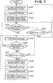
- step S400 the timing generator 110 is set to the moving image_AF mode. With this operation, lines having a small number of focus detecting pixels are read out from the image sensor 101.
- step S401 autofocus is performed.
- phase difference detection is performed using AF data extracted from the image data read out from the image sensor 101, as in the still image sensing.
- the lens position is moved by moving the lens barrel by a lens barrel control unit 111 so as to reduce the phase difference, thereby adjusting the focus.
- step S402 the timing generator 110 is set to the recording/display mode. With this operation, lines including no focus detecting pixels are read out from the image sensor 101.
- step S403 it is checked whether the moving image sensing start button is pressed in the operation unit 112. If the moving image sensing start button is not pressed ("NO" in step S403), the process advances to step S404.
- step S404 the timer value is compared with a preset value to check the time which has elapsed from the previous autofocus.
- Fig. 7 exemplifies a case in which the timer value is compared with 0.2 sec
- the present invention is not particularly limited to this. If 0.2 sec or more has elapsed already ("YES" in step S404), the process returns to step S400. If 0.2 sec or more has not elapsed yet ("NO" in step S404), step S403 is repeated.
- step S405 a moving image is captured and the image data is recorded on the recording medium 116.
- step S406 it is checked whether the moving image sensing end button is pressed in the operation unit 112. If the moving image sensing end button is pressed ("YES” in step S406), the process returns to step S403. If the moving image sensing end button is not pressed ("NO” in step S406), the process advances to step S407.
- step S407 it is checked whether a preset time (e.g., 0.2 sec in Fig. 7 ) or more has elapsed from the previous autofocus until the process shifts to step S407. If 0.2 sec or more has not elapsed yet ("NO" in step S407), the process returns to step S405, and a moving image is captured and the image data is recorded on the recording medium 116. If 0.2 sec or more has elapsed already ("YES" in step S407), the process advances to step S408.
- a preset time e.g., 0.2 sec in Fig. 7
- step S408 the timing generator 110 is set to the moving image_AF mode. With this operation, lines having a small number of focus detecting pixels are read out from the image sensor 101.
- step S409 autofocus is performed.
- step S410 a moving image is captured and the image data is recorded on the recording medium 116.
- the image recorded at this time is the one generated from the image data read out by setting the timing generator 110 to the moving image_AF mode.
- step S411 the timing generator 110 is set to the recording/display mode. The process then returns to step S405, and the process sequence is repeated. After that, the process sequence from step S400 is repeated until the power supply is turned off by the operation unit 112.
- lines including no photoelectric conversion elements for phase difference AF are read out from the image sensor 101 by the above-described process sequence if autofocus is not performed. If autofocus is performed, lines having a small number of focus detecting pixels are read out from the image sensor 101 in order to record a moving image with a quality better than that of the EVF image in the still image sensing. This makes it possible to record a moving image with a quality better than that of the EVF image.
Landscapes
- Physics & Mathematics (AREA)
- Engineering & Computer Science (AREA)
- Multimedia (AREA)
- Signal Processing (AREA)
- General Physics & Mathematics (AREA)
- Optics & Photonics (AREA)
- Computer Vision & Pattern Recognition (AREA)
- Studio Devices (AREA)
- Focusing (AREA)
- Automatic Focus Adjustment (AREA)
Applications Claiming Priority (2)
| Application Number | Priority Date | Filing Date | Title |
|---|---|---|---|
| JP2007276757A JP5002412B2 (ja) | 2007-10-24 | 2007-10-24 | 撮像装置 |
| PCT/JP2008/068251 WO2009054263A1 (en) | 2007-10-24 | 2008-10-01 | Image sensing apparatus |
Publications (3)
| Publication Number | Publication Date |
|---|---|
| EP2212731A1 EP2212731A1 (en) | 2010-08-04 |
| EP2212731A4 EP2212731A4 (en) | 2012-07-04 |
| EP2212731B1 true EP2212731B1 (en) | 2017-05-31 |
Family
ID=40579369
Family Applications (1)
| Application Number | Title | Priority Date | Filing Date |
|---|---|---|---|
| EP08841526.0A Active EP2212731B1 (en) | 2007-10-24 | 2008-10-01 | Image sensing apparatus |
Country Status (5)
| Country | Link |
|---|---|
| US (1) | US8405761B2 (ja) |
| EP (1) | EP2212731B1 (ja) |
| JP (1) | JP5002412B2 (ja) |
| CN (1) | CN101836150B (ja) |
| WO (1) | WO2009054263A1 (ja) |
Families Citing this family (12)
| Publication number | Priority date | Publication date | Assignee | Title |
|---|---|---|---|---|
| JP5361535B2 (ja) * | 2009-05-25 | 2013-12-04 | キヤノン株式会社 | 撮像装置 |
| JP5279638B2 (ja) * | 2009-07-08 | 2013-09-04 | キヤノン株式会社 | 撮像装置 |
| JP5595014B2 (ja) * | 2009-11-09 | 2014-09-24 | キヤノン株式会社 | 撮像装置 |
| JP5693082B2 (ja) | 2010-08-09 | 2015-04-01 | キヤノン株式会社 | 撮像装置 |
| JP5835996B2 (ja) * | 2011-08-08 | 2015-12-24 | オリンパス株式会社 | 撮像装置 |
| KR20130104756A (ko) * | 2012-03-15 | 2013-09-25 | 삼성전자주식회사 | 영상 촬영 장치 및 이에 포함된 이미지 센서 |
| CN104221365B (zh) * | 2012-03-30 | 2018-11-06 | 株式会社尼康 | 拍摄元件、摄影方法及拍摄装置 |
| US9191566B2 (en) * | 2012-03-30 | 2015-11-17 | Samsung Electronics Co., Ltd. | Image pickup apparatus, method for image pickup and computer-readable recording medium |
| JP5501405B2 (ja) * | 2012-05-18 | 2014-05-21 | キヤノン株式会社 | 制御装置 |
| JP6127869B2 (ja) * | 2013-09-25 | 2017-05-17 | ソニー株式会社 | 固体撮像素子及びその駆動方法、並びに電子機器 |
| CN106161958A (zh) * | 2016-08-24 | 2016-11-23 | 广西小草信息产业有限责任公司 | 一种电子控制的摄像方法及其装置 |
| JPWO2021010070A1 (ja) * | 2019-07-12 | 2021-01-21 |
Family Cites Families (11)
| Publication number | Priority date | Publication date | Assignee | Title |
|---|---|---|---|---|
| JP3592147B2 (ja) | 1998-08-20 | 2004-11-24 | キヤノン株式会社 | 固体撮像装置 |
| JP4421793B2 (ja) * | 2001-07-13 | 2010-02-24 | 富士フイルム株式会社 | ディジタルカメラ |
| JP2003198925A (ja) | 2001-12-25 | 2003-07-11 | Canon Inc | 撮像装置及び撮像方法及び制御プログラム及び記録媒体 |
| CN1464737A (zh) * | 2002-06-27 | 2003-12-31 | 力捷电脑股份有限公司 | 具有多种像素尺寸的图像传感器 |
| CN1412595A (zh) * | 2002-12-02 | 2003-04-23 | 中国科学院上海技术物理研究所 | 光瞳分割分光的双波段光学成像系统 |
| JP2004222062A (ja) * | 2003-01-16 | 2004-08-05 | Canon Inc | 撮像装置 |
| JP4458236B2 (ja) * | 2003-09-30 | 2010-04-28 | パナソニック株式会社 | 固体撮像装置 |
| JP4564831B2 (ja) * | 2004-11-26 | 2010-10-20 | キヤノン株式会社 | 撮像装置及びその制御方法 |
| JP4967296B2 (ja) * | 2005-10-03 | 2012-07-04 | 株式会社ニコン | 撮像素子、焦点検出装置、および、撮像システム |
| JP4807131B2 (ja) * | 2006-04-05 | 2011-11-02 | 株式会社ニコン | 撮像素子および撮像装置 |
| US7989745B2 (en) * | 2007-10-01 | 2011-08-02 | Nikon Corporation | Solid-state imaging device with focus detection and electronic camera with focus adjustment |
-
2007
- 2007-10-24 JP JP2007276757A patent/JP5002412B2/ja not_active Expired - Fee Related
-
2008
- 2008-10-01 EP EP08841526.0A patent/EP2212731B1/en active Active
- 2008-10-01 CN CN2008801131671A patent/CN101836150B/zh not_active Expired - Fee Related
- 2008-10-01 WO PCT/JP2008/068251 patent/WO2009054263A1/en active Application Filing
- 2008-10-01 US US12/680,529 patent/US8405761B2/en active Active
Also Published As
| Publication number | Publication date |
|---|---|
| EP2212731A1 (en) | 2010-08-04 |
| WO2009054263A1 (en) | 2009-04-30 |
| US8405761B2 (en) | 2013-03-26 |
| JP5002412B2 (ja) | 2012-08-15 |
| CN101836150B (zh) | 2013-01-16 |
| US20100214431A1 (en) | 2010-08-26 |
| JP2009103997A (ja) | 2009-05-14 |
| CN101836150A (zh) | 2010-09-15 |
| EP2212731A4 (en) | 2012-07-04 |
Similar Documents
| Publication | Publication Date | Title |
|---|---|---|
| EP2212731B1 (en) | Image sensing apparatus | |
| EP2181349B1 (en) | Image sensing apparatus | |
| JP5241355B2 (ja) | 撮像装置とその制御方法 | |
| US8964061B2 (en) | Image capturing apparatus with selection of thinning and readout mode in accordance with moving image recording mode | |
| US8817165B2 (en) | Image capturing apparatus | |
| US20140340565A1 (en) | Image capturing apparatus and control method thereof | |
| JP3395770B2 (ja) | デジタルスチルカメラ | |
| US9357121B2 (en) | Image capturing apparatus and control method thereof | |
| JP4019235B2 (ja) | 撮像デバイスの駆動方法及び電子カメラ | |
| US9888165B2 (en) | Image capturing apparatus, control method therefor and storage medium | |
| JP2006261929A (ja) | 撮像装置 | |
| JP6960755B2 (ja) | 撮像装置及びその制御方法、プログラム、記憶媒体 | |
| JPH0943507A (ja) | 電子スチルカメラおよびそのフォーカス制御方法 | |
| JP3551932B2 (ja) | 測距装置及びそれを用いた撮像装置 | |
| JP2009031343A (ja) | カメラ | |
| US11025884B2 (en) | Image capturing apparatus, control method thereof, and storage medium | |
| JP2008187614A (ja) | 撮影装置 | |
| JPH09181954A (ja) | 電子スチルカメラおよびそのフォーカス制御方法 | |
| JP2001230966A (ja) | 電子カメラ | |
| JP5550333B2 (ja) | 撮像装置、現像方法及びプログラム | |
| JP5501405B2 (ja) | 制御装置 | |
| JP2007226141A (ja) | 撮影装置及び方法 | |
| JP4618280B2 (ja) | 電子カメラ | |
| JP2001069516A (ja) | カラー撮像装置およびそれを用いたデジタルスチルカメラ | |
| JP2001083405A (ja) | 焦点検出装置及び焦点検出方法並びに記憶媒体 |
Legal Events
| Date | Code | Title | Description |
|---|---|---|---|
| PUAI | Public reference made under article 153(3) epc to a published international application that has entered the european phase |
Free format text: ORIGINAL CODE: 0009012 |
|
| 17P | Request for examination filed |
Effective date: 20100525 |
|
| AK | Designated contracting states |
Kind code of ref document: A1 Designated state(s): AT BE BG CH CY CZ DE DK EE ES FI FR GB GR HR HU IE IS IT LI LT LU LV MC MT NL NO PL PT RO SE SI SK TR |
|
| AX | Request for extension of the european patent |
Extension state: AL BA MK RS |
|
| DAX | Request for extension of the european patent (deleted) | ||
| A4 | Supplementary search report drawn up and despatched |
Effective date: 20120601 |
|
| RIC1 | Information provided on ipc code assigned before grant |
Ipc: H04N 101/00 20060101ALI20120525BHEP Ipc: G02B 7/28 20060101AFI20120525BHEP Ipc: H04N 5/232 20060101ALI20120525BHEP Ipc: G02B 7/34 20060101ALI20120525BHEP Ipc: G03B 13/36 20060101ALI20120525BHEP Ipc: H04N 5/335 20110101ALI20120525BHEP |
|
| 17Q | First examination report despatched |
Effective date: 20131007 |
|
| GRAP | Despatch of communication of intention to grant a patent |
Free format text: ORIGINAL CODE: EPIDOSNIGR1 |
|
| INTG | Intention to grant announced |
Effective date: 20161213 |
|
| GRAS | Grant fee paid |
Free format text: ORIGINAL CODE: EPIDOSNIGR3 |
|
| GRAA | (expected) grant |
Free format text: ORIGINAL CODE: 0009210 |
|
| AK | Designated contracting states |
Kind code of ref document: B1 Designated state(s): AT BE BG CH CY CZ DE DK EE ES FI FR GB GR HR HU IE IS IT LI LT LU LV MC MT NL NO PL PT RO SE SI SK TR |
|
| REG | Reference to a national code |
Ref country code: CH Ref legal event code: EP Ref country code: GB Ref legal event code: FG4D |
|
| REG | Reference to a national code |
Ref country code: AT Ref legal event code: REF Ref document number: 897985 Country of ref document: AT Kind code of ref document: T Effective date: 20170615 |
|
| REG | Reference to a national code |
Ref country code: IE Ref legal event code: FG4D |
|
| REG | Reference to a national code |
Ref country code: DE Ref legal event code: R096 Ref document number: 602008050507 Country of ref document: DE |
|
| REG | Reference to a national code |
Ref country code: NL Ref legal event code: MP Effective date: 20170531 |
|
| REG | Reference to a national code |
Ref country code: LT Ref legal event code: MG4D |
|
| REG | Reference to a national code |
Ref country code: AT Ref legal event code: MK05 Ref document number: 897985 Country of ref document: AT Kind code of ref document: T Effective date: 20170531 |
|
| PG25 | Lapsed in a contracting state [announced via postgrant information from national office to epo] |
Ref country code: ES Free format text: LAPSE BECAUSE OF FAILURE TO SUBMIT A TRANSLATION OF THE DESCRIPTION OR TO PAY THE FEE WITHIN THE PRESCRIBED TIME-LIMIT Effective date: 20170531 Ref country code: HR Free format text: LAPSE BECAUSE OF FAILURE TO SUBMIT A TRANSLATION OF THE DESCRIPTION OR TO PAY THE FEE WITHIN THE PRESCRIBED TIME-LIMIT Effective date: 20170531 Ref country code: FI Free format text: LAPSE BECAUSE OF FAILURE TO SUBMIT A TRANSLATION OF THE DESCRIPTION OR TO PAY THE FEE WITHIN THE PRESCRIBED TIME-LIMIT Effective date: 20170531 Ref country code: AT Free format text: LAPSE BECAUSE OF FAILURE TO SUBMIT A TRANSLATION OF THE DESCRIPTION OR TO PAY THE FEE WITHIN THE PRESCRIBED TIME-LIMIT Effective date: 20170531 Ref country code: NO Free format text: LAPSE BECAUSE OF FAILURE TO SUBMIT A TRANSLATION OF THE DESCRIPTION OR TO PAY THE FEE WITHIN THE PRESCRIBED TIME-LIMIT Effective date: 20170831 Ref country code: LT Free format text: LAPSE BECAUSE OF FAILURE TO SUBMIT A TRANSLATION OF THE DESCRIPTION OR TO PAY THE FEE WITHIN THE PRESCRIBED TIME-LIMIT Effective date: 20170531 Ref country code: GR Free format text: LAPSE BECAUSE OF FAILURE TO SUBMIT A TRANSLATION OF THE DESCRIPTION OR TO PAY THE FEE WITHIN THE PRESCRIBED TIME-LIMIT Effective date: 20170901 |
|
| PG25 | Lapsed in a contracting state [announced via postgrant information from national office to epo] |
Ref country code: BG Free format text: LAPSE BECAUSE OF FAILURE TO SUBMIT A TRANSLATION OF THE DESCRIPTION OR TO PAY THE FEE WITHIN THE PRESCRIBED TIME-LIMIT Effective date: 20170831 Ref country code: SE Free format text: LAPSE BECAUSE OF FAILURE TO SUBMIT A TRANSLATION OF THE DESCRIPTION OR TO PAY THE FEE WITHIN THE PRESCRIBED TIME-LIMIT Effective date: 20170531 Ref country code: IS Free format text: LAPSE BECAUSE OF FAILURE TO SUBMIT A TRANSLATION OF THE DESCRIPTION OR TO PAY THE FEE WITHIN THE PRESCRIBED TIME-LIMIT Effective date: 20170930 Ref country code: LV Free format text: LAPSE BECAUSE OF FAILURE TO SUBMIT A TRANSLATION OF THE DESCRIPTION OR TO PAY THE FEE WITHIN THE PRESCRIBED TIME-LIMIT Effective date: 20170531 Ref country code: NL Free format text: LAPSE BECAUSE OF FAILURE TO SUBMIT A TRANSLATION OF THE DESCRIPTION OR TO PAY THE FEE WITHIN THE PRESCRIBED TIME-LIMIT Effective date: 20170531 |
|
| PG25 | Lapsed in a contracting state [announced via postgrant information from national office to epo] |
Ref country code: CZ Free format text: LAPSE BECAUSE OF FAILURE TO SUBMIT A TRANSLATION OF THE DESCRIPTION OR TO PAY THE FEE WITHIN THE PRESCRIBED TIME-LIMIT Effective date: 20170531 Ref country code: EE Free format text: LAPSE BECAUSE OF FAILURE TO SUBMIT A TRANSLATION OF THE DESCRIPTION OR TO PAY THE FEE WITHIN THE PRESCRIBED TIME-LIMIT Effective date: 20170531 Ref country code: SK Free format text: LAPSE BECAUSE OF FAILURE TO SUBMIT A TRANSLATION OF THE DESCRIPTION OR TO PAY THE FEE WITHIN THE PRESCRIBED TIME-LIMIT Effective date: 20170531 Ref country code: RO Free format text: LAPSE BECAUSE OF FAILURE TO SUBMIT A TRANSLATION OF THE DESCRIPTION OR TO PAY THE FEE WITHIN THE PRESCRIBED TIME-LIMIT Effective date: 20170531 Ref country code: DK Free format text: LAPSE BECAUSE OF FAILURE TO SUBMIT A TRANSLATION OF THE DESCRIPTION OR TO PAY THE FEE WITHIN THE PRESCRIBED TIME-LIMIT Effective date: 20170531 |
|
| PG25 | Lapsed in a contracting state [announced via postgrant information from national office to epo] |
Ref country code: PL Free format text: LAPSE BECAUSE OF FAILURE TO SUBMIT A TRANSLATION OF THE DESCRIPTION OR TO PAY THE FEE WITHIN THE PRESCRIBED TIME-LIMIT Effective date: 20170531 Ref country code: IT Free format text: LAPSE BECAUSE OF FAILURE TO SUBMIT A TRANSLATION OF THE DESCRIPTION OR TO PAY THE FEE WITHIN THE PRESCRIBED TIME-LIMIT Effective date: 20170531 |
|
| PGFP | Annual fee paid to national office [announced via postgrant information from national office to epo] |
Ref country code: GB Payment date: 20171101 Year of fee payment: 10 |
|
| REG | Reference to a national code |
Ref country code: DE Ref legal event code: R097 Ref document number: 602008050507 Country of ref document: DE |
|
| PLBE | No opposition filed within time limit |
Free format text: ORIGINAL CODE: 0009261 |
|
| STAA | Information on the status of an ep patent application or granted ep patent |
Free format text: STATUS: NO OPPOSITION FILED WITHIN TIME LIMIT |
|
| 26N | No opposition filed |
Effective date: 20180301 |
|
| PG25 | Lapsed in a contracting state [announced via postgrant information from national office to epo] |
Ref country code: MC Free format text: LAPSE BECAUSE OF FAILURE TO SUBMIT A TRANSLATION OF THE DESCRIPTION OR TO PAY THE FEE WITHIN THE PRESCRIBED TIME-LIMIT Effective date: 20170531 Ref country code: SI Free format text: LAPSE BECAUSE OF FAILURE TO SUBMIT A TRANSLATION OF THE DESCRIPTION OR TO PAY THE FEE WITHIN THE PRESCRIBED TIME-LIMIT Effective date: 20170531 |
|
| REG | Reference to a national code |
Ref country code: CH Ref legal event code: PL |
|
| REG | Reference to a national code |
Ref country code: IE Ref legal event code: MM4A |
|
| REG | Reference to a national code |
Ref country code: FR Ref legal event code: ST Effective date: 20180629 |
|
| PG25 | Lapsed in a contracting state [announced via postgrant information from national office to epo] |
Ref country code: LU Free format text: LAPSE BECAUSE OF NON-PAYMENT OF DUE FEES Effective date: 20171001 Ref country code: CH Free format text: LAPSE BECAUSE OF NON-PAYMENT OF DUE FEES Effective date: 20171031 Ref country code: LI Free format text: LAPSE BECAUSE OF NON-PAYMENT OF DUE FEES Effective date: 20171031 |
|
| REG | Reference to a national code |
Ref country code: BE Ref legal event code: MM Effective date: 20171031 |
|
| PG25 | Lapsed in a contracting state [announced via postgrant information from national office to epo] |
Ref country code: FR Free format text: LAPSE BECAUSE OF NON-PAYMENT OF DUE FEES Effective date: 20171031 Ref country code: BE Free format text: LAPSE BECAUSE OF NON-PAYMENT OF DUE FEES Effective date: 20171031 |
|
| PG25 | Lapsed in a contracting state [announced via postgrant information from national office to epo] |
Ref country code: MT Free format text: LAPSE BECAUSE OF NON-PAYMENT OF DUE FEES Effective date: 20171001 |
|
| PG25 | Lapsed in a contracting state [announced via postgrant information from national office to epo] |
Ref country code: IE Free format text: LAPSE BECAUSE OF NON-PAYMENT OF DUE FEES Effective date: 20171001 |
|
| GBPC | Gb: european patent ceased through non-payment of renewal fee |
Effective date: 20181001 |
|
| PG25 | Lapsed in a contracting state [announced via postgrant information from national office to epo] |
Ref country code: HU Free format text: LAPSE BECAUSE OF FAILURE TO SUBMIT A TRANSLATION OF THE DESCRIPTION OR TO PAY THE FEE WITHIN THE PRESCRIBED TIME-LIMIT; INVALID AB INITIO Effective date: 20081001 |
|
| PG25 | Lapsed in a contracting state [announced via postgrant information from national office to epo] |
Ref country code: CY Free format text: LAPSE BECAUSE OF NON-PAYMENT OF DUE FEES Effective date: 20170531 Ref country code: GB Free format text: LAPSE BECAUSE OF NON-PAYMENT OF DUE FEES Effective date: 20181001 |
|
| PG25 | Lapsed in a contracting state [announced via postgrant information from national office to epo] |
Ref country code: TR Free format text: LAPSE BECAUSE OF FAILURE TO SUBMIT A TRANSLATION OF THE DESCRIPTION OR TO PAY THE FEE WITHIN THE PRESCRIBED TIME-LIMIT Effective date: 20170531 |
|
| PG25 | Lapsed in a contracting state [announced via postgrant information from national office to epo] |
Ref country code: PT Free format text: LAPSE BECAUSE OF FAILURE TO SUBMIT A TRANSLATION OF THE DESCRIPTION OR TO PAY THE FEE WITHIN THE PRESCRIBED TIME-LIMIT Effective date: 20170531 |
|
| PGFP | Annual fee paid to national office [announced via postgrant information from national office to epo] |
Ref country code: DE Payment date: 20230920 Year of fee payment: 16 |