EP2212479B1 - Aufgehängter unterwassertunnel - Google Patents
Aufgehängter unterwassertunnel Download PDFInfo
- Publication number
- EP2212479B1 EP2212479B1 EP07815921A EP07815921A EP2212479B1 EP 2212479 B1 EP2212479 B1 EP 2212479B1 EP 07815921 A EP07815921 A EP 07815921A EP 07815921 A EP07815921 A EP 07815921A EP 2212479 B1 EP2212479 B1 EP 2212479B1
- Authority
- EP
- European Patent Office
- Prior art keywords
- tunnel
- shaft
- section
- tunnel section
- ties
- Prior art date
- Legal status (The legal status is an assumption and is not a legal conclusion. Google has not performed a legal analysis and makes no representation as to the accuracy of the status listed.)
- Not-in-force
Links
Images


Classifications
-
- E—FIXED CONSTRUCTIONS
- E21—EARTH DRILLING; MINING
- E21D—SHAFTS; TUNNELS; GALLERIES; LARGE UNDERGROUND CHAMBERS
- E21D9/00—Tunnels or galleries, with or without linings; Methods or apparatus for making thereof; Layout of tunnels or galleries
- E21D9/14—Layout of tunnels or galleries; Constructional features of tunnels or galleries, not otherwise provided for, e.g. portals, day-light attenuation at tunnel openings
-
- E—FIXED CONSTRUCTIONS
- E02—HYDRAULIC ENGINEERING; FOUNDATIONS; SOIL SHIFTING
- E02D—FOUNDATIONS; EXCAVATIONS; EMBANKMENTS; UNDERGROUND OR UNDERWATER STRUCTURES
- E02D29/00—Independent underground or underwater structures; Retaining walls
- E02D29/063—Tunnels submerged into, or built in, open water
- E02D29/067—Floating tunnels; Submerged bridge-like tunnels, i.e. tunnels supported by piers or the like above the water-bed
Definitions
- This invention relates to an underwater suspended tunnel connecting two land masses separated by a body of water.
- Bridges are common structures for carrying pedestrian, vehicular, rail traffic and the like over a body of water. If it is neither feasible nor cost effective to construct a bridge, or if an alternate transportation link is desired to alleviate congestion on an existing bridge, an underwater tunnel may be constructed to carry traffic between two land masses separated by a body of water. Underwater tunnels have been constructed by boring a tunnel through the earth beneath the sea bed ("sea" is used herein to refer to any body of water including oceans, lakes and rivers).
- Underwater tunnels have also been constructed by dredging a trench in the sea bed, lowering preformed tubular sections into the trench, joining the sections together to form one continuous tunnel, backfilling exposed portions of the trench and covering the tunnel with concrete, rock, dirt, mud or other material to hold the tunnel permanently in place on the sea bed.
- the latter type of tunnel is often referred to as an "immersed tunnel”.
- immersed tunnels include:
- JP 7 048849 A discloses an underwater tunnel according to the preamble of claim 1 with tube bodies set with the tare weight value and tunnel volume value so that the ratio obtained when the sum of the estimated maximum traffic load value and the tare weight value is divided by the tunnel volume value is made smaller than the specific gravity of water. Mooring members are fixed to the sea bottom via anchor bodies.
- FIG. 1 shows a suspended underwater tunnel 6 extending between two opposing land masses 2a, 2b separated by a body of water 3 having a bed 4 and a sea level 5 which may vary according to tides.
- Tunnel 6 has an elongate, positively buoyant shaft 10 which is maintained at a generally uniform depth d below sea level 5 by a series of anchors 30 tethering shaft 10 to bed 4.
- Anchors 30 include ties 32 coupled between the sides of shaft 10 and anchor blocks 34 on bed 4.
- Tunnel 6 also has entrances 17a, 17b at either end connecting to entry/exit tunnels (not shown in Figure 1 ) at land masses 2a, 2b for entry/exit of vehicular or other traffic.
- Shaft 10 may slope downwardly from entrances 17a, 17b to reach depth d.
- the top of shaft 10 is preferably submerged at least 20 meters below low tide level to avoid collision with boats passing over tunnel 6.
- shaft 10 remains substantially level over undulating sea bed terrain, given that the height of anchors 30 varies along the length of tunnel 6 to accommodate varying levels in bed 4. Since shaft 10 is suspended above bed 4 rather than being immersed in bed 4, shaft 10 may be constructed in deeper water than is generally feasible for immersed tunnels, and shaft 10 may be constructed above many different kinds of sea bed terrain, including rocky sea bed terrain.
- Shaft 10 is formed of a plurality of longitudinally interconnected sections 11, which are generally identical to one another in shape and size.
- the length of each section 11 may be selected taking into account the costs of installing and interconnecting sections 11, the costs of creating a facility to construct sections 11 of the proposed length, etc.
- Each section 11 may be about 500 meters in length.
- shaft 10 (and each section 11) is streamlined in transversely opposed directions.
- Shaft 10 has generally convex outer upper and lower surfaces 12,13 meeting along longitudinally-extending, transversely streamlined sides 14, 15.
- Shaft 10 is formed of material which is strong in compression, such as reinforced, high-density concrete (represented as the cross-hatched portion of shaft 10 in Figure 2 ).
- Shaft 10 has at least two longitudinally extending apertures for passage of vehicular or other traffic.
- upper and lower vehicle apertures 20 a , 20 b extend parallel to one another through a central longitudinal portion of shaft 10.
- Vehicle apertures 20 a , 20 b are wide enough to accommodate at least two lanes of traffic each, so that if there is a stall or breakdown in one lane, vehicles may pass in the other lane and emergency vehicles may access the problem vehicle.
- Each vehicle aperture may be approximately 5 meters high by 8 meters wide (allowing for two lanes of traffic each 4 meters wide).
- At least one additional aperture may extend longitudinally through shaft 10 to accommodate extra lanes of traffic or other transportation systems (e.g. light rail or rapid transit). These additional apertures may also be used for ventilation systems, electrical systems, equipment storage, emergency access, maintenance access and the like.
- Figure 2 shows first and second lateral apertures 22 a , 22 b extending adjacent sides 14, 15 respectively, and alongside vehicle apertures 20 a , 20 b .
- Apertures 22a, 22b may be each 5 metres high by 4 metres wide.
- Passageways (not shown) provided at spaced intervals along shaft 10 may extend transversely between apertures 22 a , 22 b and central vehicle apertures 20 a , 20 b to permit emergency and maintenance crews to access vehicle apertures 20 a , 20 b .
- Shaft 10 (and each tunnel section 11) is designed to have positive net buoyancy.
- the buoyancy is sufficient to offset the maximum expected load of traffic and equipment, while maintaining tension in ties 32 for greater stability of tunnel 6.
- a sufficient volume of air is contained in the apertures of shaft 10 such that the overall weight of shaft 10, including any load that it is carrying, is less than the weight of the water displaced by shaft 10.
- the requirement for net buoyancy places design constraints on the amount of concrete used to form shaft 10 and the number and size of the apertures.
- the total volume of the apertures is approximately 120 cubic metres per meter of tunnel length, which would require approximately 86 cubic metres of high-density concrete per metre of tunnel length to offset the volume of air in the apertures to achieve neutral buoyancy (assuming that the concrete has a specific density of about 2.4).
- an expected traffic and equipment load of 5 or 6 tonnes per meter of tunnel length
- shaft 10 and arrangement of the apertures are also constrained by the need to withstand significant hydrostatic pressure acting on shaft 10.
- the hydrostatic pressure is approximately 35 tonnes per square meter.
- aperture 20b is 8 metres wide, a force of about 280 tonnes is imposed per metre of tunnel length on the bottom of aperture 20b.
- the expected traffic and equipment load is only about 2.5 tonnes per metre of tunnel length, or about 1% of the hydrostatic bending stress.
- hydrostatic pressure is handled by compression stresses in the concrete instead of bending stresses.
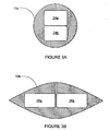
- tunnel 6 is cylindrical in cross-section, as shown by shaft 10a in Figure 3A
- upper and lower vehicle apertures 24a, 24b may be provided to accommodate two lanes of traffic each.
- Hydrostatic pressure results in compression stresses acting around the cylindrical surface, with relatively low bending stresses as compared with other tunnel shapes and aperture configurations.
- shaft 10a may have a tendency to be somewhat unstable in currents, as the cylindrical shape may lead to turbulence in the waters surrounding shaft 10a which would cause shaft 10a to oscillate.
- Figure 3B illustrates a streamlined shaft 10b having two vehicle apertures 26a, 26b arranged side-by-side to accommodate two lanes of traffic each.
- Shaft 10b which is streamlined in transversely opposed directions, has improved stability in currents in comparison to cylindrical shaft 10a.
- hydrostatic pressure introduces significant bending stresses across shaft 10b.
- a substantial amount of reinforcement would be required to counteract these bending stresses (e.g. reinforcing bars and concrete especially around the top and bottom of apertures 26a, 26b).
- Such reinforcement can be expensive and adds to the weight of shaft 10b, making it impractical to achieve positive net buoyancy of shaft 10b.
- Shaft 10 is symmetrical about a vertical plane V-V ( Figure 2 ) both with respect to the outside shape of shaft 10 and the interior aperture arrangement.
- the outside shape of shaft 10 is also symmetrical about a horizontal plane H-H passing through the axis of the shaft.
- the interior arrangement of apertures is not necessarily symmetrical about horizontal plane H-H.
- the position of vehicle apertures 20a, 20b may be elevated so that there is more concrete below aperture 20b than above aperture 20a.
- apertures 22a, 22b may be elevated.
- shaft 10 is maintained at a generally uniform depth d below sea level 5 by a plurality of anchors 30 which are longitudinally spaced along shaft 10. Pairs of opposing anchors 30 (one on each side 14, 15) are provided along the length of shaft 10 to offset eccentric loads in shaft 10.
- Each anchor 30 includes a generally vertical tie 32 coupled between an anchor block 34 on bed 4 and one of shaft 10' s sides 14, 15. Ties 32 may be rods, a plurality of longitudinally linked rods, cables or chain-links. The length of each tie 32 is variable to maintain shaft 10 at its desired depth below sea level 5 despite variations in the level of bed 4.
- the height of anchor blocks 34 may also be variable. At certain locations along shaft 10 (e.g. deep water locations) it may be desirable to provide tall anchor blocks 34 to reduce the length of ties 32, thereby making it easier to install and maintain ties 32.
- each tie 32 is advantageously adjustable.
- a possible mechanism for adjusting the tension in ties 32 is shown in Figure 2 .
- a pair of ties 32 are inserted through channels in sides 14, 15 respectively, and a nut 25 is screwed to the top end of each tie 32. Tightening of nut 25 increases the tension in tie 32.
- Ties 32 are subject to tension which is equal and opposite to the positive net buoyancy of shaft 10.
- the tension in ties 32 is reduced when shaft 10 is carrying a load from the passage of traffic.
- pairs of opposing anchors 30 are spaced apart longitudinally along the shaft by approximately 50 meters. If the positive net buoyancy of shaft 10 without a traffic load is 5 to 6 tonnes per meter of tunnel length, every 50 meter length of the shaft therefore has a maximum net buoyancy of 250 to 300 tonnes, and the upward buoyancy force exerted on each anchor 30 is 125 to 150 tonnes.
- Each anchor block 34 should have an overall weight on bed 4 which is at least equal to the buoyancy force of 125 to 150 tonnes exerted on each anchor 30 in order to tether shaft 10 at a fixed height above bed 4.
- lateral forces acting on shaft 10 due to tidal currents, tsunamis and the like. These forces are relatively small in comparison to the net buoyancy of 2500 to 3000 tonnes per 500 metre length of shaft 10. For example, it is estimated that a tidal current of 2 knots results in a lateral force of 20 tonnes on each 500 metre-long section, a tidal current of 4 knots results in a lateral force of 80 tonnes per 500 metre-long section, and a tidal current of 8 knots results in a lateral force of 320 tonnes per 500 metre-long section.
- the lateral forces may be resisted by pairs of crossties 36 extending diagonally between opposing anchors 30 as shown in Figure 2 .
- Crossties 36 are secured to a side 14 or 15 and to an anchor block 34 of an anchor 30 on the opposite side.
- Crossties 36 are not necessarily attached between every pair of opposing anchors 30. However, at least two pairs of crossties 36 should be provided for each tunnel section 11.
- Crossties 36 may be rods, a plurality of longitudinally linked rods, cables or chain-links, and the tension in crossties 36 is advantageously adjustable.
- each crosstie 36 may be secured to a separate crosstie block on bed 4.
- Ties 32 and crossties 36, and any attachment or coupling devices used may be made of corrosion-resistant materials such as stainless steel, or may be treated with a corrosion-resistant coating.
- the outer surface of each section 11 may advantageously have a waterproofing and corrosion-resistant coating.
- Ventilation systems; electrical systems; lighting; fire suppression systems; remote camera systems; emergency warning systems; and leak detection systems, pumps and pimping may be installed in shaft 10.
- tunnel seals are typically made of elastomeric material (such as rubber) and may, for example, include an O-ring and/or interlocking flanges in the gap between two abutting portions of section 11.
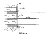
- FIG. 4 shows expansion joints at a land-tunnel interface between shaft 10 and land mass 2b.
- a connecting wall 50 is constructed at the interface with an aperture for receiving shaft 11 and joining it to entranceway 17b.
- Expansion joints 56 are installed at the interface between connecting wall 50 and the outer walls of shaft 10. Expansion joints 56 may be smooth pads (such as Teflon pads) which slide against one other as shaft 10 longitudinally expands and contracts.
- Figure 4 illustrates one example of a land-tunnel interface.
- Various other configurations are possible for the land-tunnel interface, and appropriate tunnel expansion joints may be provided for such configurations.
- anchor blocks 34 are placed on bed 4. This may be accomplished by tremie pour methods or by other methods known to a person of skill in the art.
- each anchor block 34 may be precast with a preformed aperture to permit the block to be floated to a site above its proposed location on bed 4. At the site, the aperture may be filled with concrete to sink the block to bed 4.
- Each tunnel section 11 may be precast in a floodable dry dock, having its gates closed and all the water pumped out. Removeable bulkheads may be installed toward each end of section 11 so that section 11 will float when the dry dock gates are opened to flood the dry dock. The bulkheads are installed as close to the ends of each section 11 as possible without interfering with the coupling of adjacent sections 11. After each section 11 is made, it may be floated to a temporary storage location until shaft 10 is ready to be constructed.
- each section 11 in turn is floated to its planned installation site.
- a pair of floating gantry cranes may be attached to section 11 using winches and cables, so as to provide a platform for positioning and installing section 11.
- Section 11 is subsequently sunk to the desired depth below sea level 5. This may be accomplished by placing ballast bags (or other containers) in the apertures of section 11 and pumping water into the bags.
- Sections 11 are aligned next to a previously installed, adjacent section 11.
- Sections 11 may have locating pins for aligning and coupling adjacent sections 11 to each other, and for preventing movement in the joints between sections 11.
- clamping devices may be used to hold adjacent sections 11 together during and after installation.
- ties 32 are secured to sides 14, 15 of section 11 and to anchor blocks 34 on bed 4.
- Crossties 36 may also be attached between pairs of ties 32 as shown in Figure 2 .
- the tension in ties 32 and crossties 36 may be adjusted to provide generally uniform tension in ties 32 and crossties 36 along the length of shaft 10.
- the water in the ballast bags may be pumped out. Eventually all of the water is removed from the bags so that section 11 has positive net buoyancy and is tethered to bed 4 by anchors 30.
- Adjacent sections 11 are joined together and sealed. The water is then removed from between the two bulkheads of the adjacent sections, and the seal between the sections is checked for leaks. If there are no leaks, the bulkheads may be removed, and electrical systems, lighting, ventilation fans, leak detection systems, and other systems and equipment may be installed inside section 11.
- tunnel 6 The steps used to construct tunnel 6 are not necessarily performed in the order described above but always according to claim 8. Certain steps may be performed simultaneously or divided into sub-tasks performed in combination with other steps but always according to claim 8. For example, tension in ties 32 and cross-ties 36 may be adjusted preliminarily during installation of each section 11, and fine-tuned after all of sections 11 have been interconnected to form shaft 10.
Claims (15)
- Unterwassertunnel (6), der zwei Landmassen (2a, 2b) verbindet, die durch ein Gewässer (3) getrennt sind, wobei der Tunnel (6) Folgendes umfasst:- eine längliche Röhre (10) mit einer oberen und einer unteren Außenfläche (12, 13) von allgemein konvexer Form, die sich entlang einer ersten und einer zweiten Seite (14, 15), die sich in Längsrichtung erstrecken und einander in Querrichtung gegenüber liegen, schneiden; und- eine vorspannung (30), die zwischen der Röhre (10) und einem Bett (4) des Gewässers (3) gekoppelt ist, um die Röhre (10) in einer allgemein gleichmäßigen Tiefe unter einer Oberfläche (5) des Gewässers (3) zu halten;wobei die Röhre (10) mehrere in Längsrichtung miteinander verbundene Segmente (11) umfasst, wobei jedes Segment (11) einstückig aus Stahlbeton besteht, um sowohl Ballast als auch das Tragwerk für die Röhre (10) zu bilden, und wobei ein kombiniertes Gewicht der Röhre (10) und einer erwarteten Fahrzeugbelastung in der Röhre (10) geringer ist als ein Gewicht des von der Röhre (10) verdrängten Wassers;
dadurch gekennzeichnet, dass sich die erste und die zweite Seite der Röhre in entgegengesetzten Richtungen von einer Längsachse des Tunnels (6) fort verjüngen; und dass der Tunnel eine obere und eine untere Fahrzeuggasse (20a, 20b) umfasst, die sich in Längsrichtung durch einen mittigen Teil der Röhre (10) erstreckt, damit ein Fahrzeugverkehr durch jede der Fahrzeuggassen (20a, 20b) fließen kann, wobei die obere Fahrzeuggasse (20a) parallel zu der, und oberhalb der, unteren Fahrzeuggasse (20b) verläuft und jede der Fahrzeuggassen (20a, 20b) dafür bemessen ist, mindestens zwei Fahrspuren aufzunehmen. - Tunnel nach Anspruch 1, der des Weiteren einen ersten und einen zweiten seitlichen Kanal (22a, 22b) umfasst, die in Längsrichtung durch die Röhre (10) neben der ersten und der zweiten Seite (14, 15) der Röhre (10) verlaufen.
- Tunnel nach einem der Ansprüche 1 oder 2, wobei die erste und die zweite Seite (14, 15) der Röhre (10) in quer entgegengesetzten Richtungen stromlinienförmig gestaltet sind.
- Tunnel nach einem der Ansprüche 1 bis 3, wobei die Verspannung (30) mehrere erste und mehrere zweite Zuganker (32) umfasst, wobei die mehreren ersten Zuganker in Längsrichtung entlang der ersten Seite (14) der Röhre (10) beabstandet sind und die mehreren zweiten Zuganker in Längsrichtung entlang der zweiten Seite (15) der Röhre (10) beabstandet sind, wobei jeder Zuganker (32) mit seinem unteren Ende in dem Bett (4) verankert ist.
- Tunnel nach Anspruch 4, wobei die Verspannung (30) des Weiteren mehrere erste und mehrere zweite Queranker (36) umfasst, wobei die mehreren ersten Queranker in Längsrichtung entlang der ersten Seite (14) der Röhre (10) beabstandet sind, die mehreren zweiten Queranker in Längsrichtung entlang der zweiten Seite (15) der Röhre (10) beabstandet, jeder der mehreren ersten Queranker mit dem unteren Ende an einem Ankerblock (34) eines entsprechenden der mehreren zweiten Zuganker verankert ist und jeder der mehreren zweiten Queranker mit dem unteren Ende an einem Ankerblock (34) eines entsprechenden der mehreren ersten Zuganker verankert ist.
- Tunnel nach Anspruch 5, wobei eine seitliche Kraft, die durch jeden der Queranker (36) aufgenommen wird, geringer ist als eine Auftriebskraft, die auf die mehreren ersten und die mehreren zweiten Zuganker (32) wirkt.
- Tunnel nach Anspruch 1, wobei jedes Ende des Tunnels über mindestens eine Dehnungsfuge (56) mit einer entsprechenden Tunneleinfahrt (17a, 17b) gekoppelt ist.
- Verfahren zum Bau eines Unterwassertunnels (6), der zwei Landmassen (2a, 2b) verbindet, die durch ein Gewässer (3) getrennt sind, wobei das Verfahren Folgendes umfasst:- Versenken mehrerer Tunnel-Fertigsegmente (11) auf einer Tunnelbaustelle auf eine allgemein gleichmäßige Tiefe unter einer Oberfläche (5) des Gewässers (3), wobei jedes Tunnelsegment (11) einstückig aus Stahlbeton besteht, um sowohl Ballast als auch das Tragwerk für das Tunnelsegment (11) zu bilden, und wobei jedes Tunnelsegment (11) Folgendes aufweist:• eine obere und eine untere Außenfläche (12, 13) von allgemein konvexer Form, die sich entlang einer ersten und einer zweiten Seite (14, 15), die sich in Längsrichtung erstrecken und einander in Querrichtung gegenüber liegen, schneiden und in entgegengesetzten Richtungen von einer Längsachse des Tunnels (6) fort verjüngen, und• eine obere und eine untere Fahrzeuggasse (20a, 20b), die sich in Längsrichtung durch einen mittigen Teil des Tunnelsegment (11) erstreckt, damit ein Fahrzeugverkehr durch jede der Fahrzeuggassen (20a, 20b) fließen kann, wobei die obere Fahrzeuggasse (20a) parallel zu der, und oberhalb der, unteren Fahrzeuggasse (20b) verläuft und jede der Fahrzeuggassen (20a, 20b) dafür bemessen ist, mindestens zwei Fahrspuren aufzunehmen,- Verspannen jedes Tunnelsegments (11) mit einem Bett (4) des Gewässers (3); und- Verkoppeln benachbarter Tunnelsegmente (11) in Längsrichtung, um eine längliche Röhre (10) zu bilden, wobei ein kombiniertes Gewicht der Röhre (10) und einer erwarteten Fahrzeugbelastung in der Röhre (10) geringer ist als ein Gewicht des von der Röhre (10) verdrängten Wassers.
- Verfahren nach Anspruch 8, wobei die erste und die zweite Seite (14, 15) jedes Tunnelsegments (11) in quer entgegengesetzten Richtungen stromlinienförmig gestaltet sind.
- Verfahren nach einem der Ansprüche 8 oder 9, wobei das Versenken der Tunnelsegmente (11) des Weiteren umfasst, Wasser in Behälter innerhalb jedes Tunnelsegments (11) zu pumpen.
- Verfahren nach Anspruch 10, das des Weiteren umfasst, das Wasser aus den Behältern in jedem Tunnelsegment (11) zu entfernen, nachdem das Tunnelsegment (11) mit dem Bett verspannt und mit dem benachbarten Tunnelsegment (11) gekoppelt wurde.
- Verfahren nach einem der Ansprüche 8 bis 11, wobei das Verspannen jedes Tunnelsegments (11) Folgendes umfasst:- Koppeln mehrerer erster Zuganker mit der ersten Seite (14) des Tunnelsegments (11) in in Längsrichtung beabstandeten Intervallen entlang des Tunnelsegments (11);- Koppeln mehrerer zweiter Zuganker mit der zweiten Seite (15) des Tunnelsegments (11) in in Längsrichtung beabstandeten Intervallen entlang des Tunnelsegments (11);- Verankern des unteren Endes eines jeden der mehreren ersten Zuganker an dem Bett (4) unter der ersten Seite (14) des Tunnelsegments (11); und- Verankern des unteren Endes eines jeden der mehreren zweiten Zuganker an dem Bett (4) unter der zweiten Seite (15) des Tunnelsegments (11).
- Verfahren nach Anspruch 12, wobei das Verspannen jedes Tunnelsegments (11) des Weiteren Folgendes umfasst:- Koppeln mehrerer erster Zuganker mit der ersten Seite (14) des Tunnelsegments (11) in in Längsrichtung beabstandeten Intervallen entlang des Tunnelsegments (11);- Koppeln mehrerer zweiter Queranker mit der zweiten Seite (15) des Tunnelsegments (11) in in Längsrichtung beabstandeten Intervallen entlang des Tunnelsegments (11);- Verankern des unteren Endes eines jeden der mehreren ersten Queranker an dem Bett (4) unter der zweiten Seite (15) des Tunnelsegments (11); und- Verankern des unteren Endes eines jeden der mehreren zweiten Zuganker an dem Bett (4) unter der ersten Seite (14) des Tunnelsegments (11).
- Verfahren nach einem der Ansprüche 8 bis 13, wobei die Tunnelsegmente (11) in einem Trockendock vorgefertigt und schwimmend zu der Tunnelbaustelle transportiert werden.
- Verfahren nach einem der Ansprüche 8 bis 14, wobei das Verkoppeln benachbarter Tunnelsegmente (11) umfasst, eine Dichtung zwischen benachbarte Tunnelsegmente (11) einzusetzen.
Applications Claiming Priority (1)
| Application Number | Priority Date | Filing Date | Title |
|---|---|---|---|
| PCT/CA2007/001733 WO2009039605A1 (en) | 2007-09-25 | 2007-09-25 | Underwater suspended tunnel |
Publications (3)
| Publication Number | Publication Date |
|---|---|
| EP2212479A1 EP2212479A1 (de) | 2010-08-04 |
| EP2212479A4 EP2212479A4 (de) | 2010-09-15 |
| EP2212479B1 true EP2212479B1 (de) | 2012-02-29 |
Family
ID=40510693
Family Applications (1)
| Application Number | Title | Priority Date | Filing Date |
|---|---|---|---|
| EP07815921A Not-in-force EP2212479B1 (de) | 2007-09-25 | 2007-09-25 | Aufgehängter unterwassertunnel |
Country Status (5)
| Country | Link |
|---|---|
| US (1) | US7942607B2 (de) |
| EP (1) | EP2212479B1 (de) |
| AT (1) | ATE547568T1 (de) |
| CA (1) | CA2679281C (de) |
| WO (1) | WO2009039605A1 (de) |
Cited By (1)
| Publication number | Priority date | Publication date | Assignee | Title |
|---|---|---|---|---|
| KR20210019717A (ko) * | 2019-08-13 | 2021-02-23 | 한국해양과학기술원 | 사장식 수중터널 계류 장치 및 그 계류 방법 |
Families Citing this family (18)
| Publication number | Priority date | Publication date | Assignee | Title |
|---|---|---|---|---|
| CN101851933B (zh) * | 2010-06-11 | 2011-12-07 | 许是勇 | 一种可潜式水下景观隧道 |
| KR101710565B1 (ko) * | 2014-05-29 | 2017-02-27 | 지에스건설 주식회사 | 해저 터널 구조물의 시공방법 |
| WO2016126502A1 (en) | 2015-02-08 | 2016-08-11 | Hyperloop Technologies, Inc | Power supply system and method for a movable vehicle within a structure |
| US9566987B2 (en) | 2015-02-08 | 2017-02-14 | Hyperloop Technologies, Inc. | Low-pressure environment structures |
| RU2643904C1 (ru) | 2015-02-08 | 2018-02-06 | Гиперлуп Текнолоджис, Инк., | Запорные клапаны и воздушные шлюзы для транспортной системы |
| AU2016215689A1 (en) * | 2015-02-08 | 2017-07-20 | Hyperloop Technologies, Inc | Transportation system |
| US9533697B2 (en) | 2015-02-08 | 2017-01-03 | Hyperloop Technologies, Inc. | Deployable decelerator |
| US9641117B2 (en) | 2015-02-08 | 2017-05-02 | Hyperloop Technologies, Inc. | Dynamic linear stator segment control |
| WO2016126494A1 (en) | 2015-02-08 | 2016-08-11 | Hyperloop Technologies, Inc. | Continuous winding for electric motors |
| WO2017075512A1 (en) | 2015-10-29 | 2017-05-04 | Hyperloop Technologies, Inc. | Variable frequency drive system |
| AT519368B1 (de) * | 2017-02-21 | 2018-06-15 | Sdo Zt Gmbh | Unterwassertunnel |
| EE05838B1 (et) * | 2018-02-02 | 2021-10-15 | Tõnu Ader | Survestatavate tihenditega moodultunnel ja selle vette paigaldamise meetod |
| GB2575850B (en) * | 2018-07-26 | 2020-08-05 | Abdulkadir Omer Bndean | Transport system using renewable energy |
| CN109183850B (zh) * | 2018-09-20 | 2019-10-08 | 杜地 | 一种海上隧道 |
| CN109653248B (zh) * | 2018-11-07 | 2020-08-04 | 浙江大学 | 一种用于锚固悬浮隧道管体的可调式锚索装置 |
| CN109610511B (zh) * | 2018-12-14 | 2019-08-23 | 黄夏羿 | 跨海水中悬浮高铁隧道结构、建造及其控制方法 |
| CN111877401B (zh) * | 2020-07-28 | 2022-03-08 | 杜同 | 一种水中交通隧道 |
| CN114960756B (zh) * | 2021-02-26 | 2024-01-09 | 宝山钢铁股份有限公司 | 一种水下挂网掩蔽式隧道及其建造方法 |
Family Cites Families (18)
| Publication number | Priority date | Publication date | Assignee | Title |
|---|---|---|---|---|
| US262524A (en) * | 1882-08-08 | John t | ||
| US131322A (en) * | 1872-09-17 | Improvement in subaqueous tunnels | ||
| US447735A (en) * | 1891-03-03 | moesee | ||
| FR522112A (fr) * | 1918-09-06 | 1921-07-25 | Robert Culmet | Procédé de sustentation de construction sur ou dans l'eau, et applications |
| GB1036441A (en) * | 1962-01-23 | 1966-07-20 | Dragan Rudolf Petrik | A transport system for high speed travel including a jet propelled locomotive |
| US3738112A (en) * | 1971-02-10 | 1973-06-12 | Grant Alan & Partners | Bridging or spanning of bodies of water |
| NO125286B (de) * | 1971-04-02 | 1972-08-14 | Norconsult As | |
| DE2423854A1 (de) * | 1974-05-16 | 1975-12-04 | Josef Boessner | Meerestunnel |
| FR2424364A1 (fr) * | 1978-03-09 | 1979-11-23 | Sfp Structures | Procede et dispositif de lancement d'un tunnel immerge |
| US4444526A (en) * | 1981-03-02 | 1984-04-24 | Dimitris Foundoukos | Submerged tunnel and a method of and means for constructing a submerged tunnel |
| GB2175944A (en) * | 1985-04-11 | 1986-12-10 | Martin James Tomlinson | Construction of submerged roadways |
| JPH04258494A (ja) * | 1991-02-08 | 1992-09-14 | Shimizu Corp | 水平長尺躯体の建造方法 |
| CA2087382A1 (en) * | 1992-01-17 | 1993-07-18 | Masateru Niimura | Underwater tunnel and an underwater mooring apparatus to moor the underwater tunnel |
| JPH0742182A (ja) * | 1992-04-28 | 1995-02-10 | Eng Shinko Kyokai | 有脚式水中トンネル及び有脚式水中トンネル工法 |
| JPH0748849A (ja) * | 1993-08-05 | 1995-02-21 | Mitsui Constr Co Ltd | 水中トンネル |
| IT1283017B1 (it) * | 1996-05-15 | 1998-04-03 | Giulio Cambiuzzi | Tunnel sommerso a sospensione galleggiante. |
| US5899635A (en) * | 1997-05-09 | 1999-05-04 | Kuja; Michael W. | Transportation underwater tunnel system |
| KR100993631B1 (ko) * | 2008-06-12 | 2010-11-11 | 삼성중공업 주식회사 | 부유식 교량 구조 |
-
2007
- 2007-09-25 WO PCT/CA2007/001733 patent/WO2009039605A1/en active Application Filing
- 2007-09-25 EP EP07815921A patent/EP2212479B1/de not_active Not-in-force
- 2007-09-25 CA CA2679281A patent/CA2679281C/en not_active Expired - Fee Related
- 2007-09-25 AT AT07815921T patent/ATE547568T1/de active
- 2007-09-25 US US12/528,874 patent/US7942607B2/en not_active Expired - Fee Related
Cited By (1)
| Publication number | Priority date | Publication date | Assignee | Title |
|---|---|---|---|---|
| KR20210019717A (ko) * | 2019-08-13 | 2021-02-23 | 한국해양과학기술원 | 사장식 수중터널 계류 장치 및 그 계류 방법 |
Also Published As
| Publication number | Publication date |
|---|---|
| CA2679281A1 (en) | 2009-04-02 |
| US7942607B2 (en) | 2011-05-17 |
| EP2212479A1 (de) | 2010-08-04 |
| EP2212479A4 (de) | 2010-09-15 |
| WO2009039605A1 (en) | 2009-04-02 |
| US20100092243A1 (en) | 2010-04-15 |
| CA2679281C (en) | 2010-04-06 |
| ATE547568T1 (de) | 2012-03-15 |
Similar Documents
| Publication | Publication Date | Title |
|---|---|---|
| EP2212479B1 (de) | Aufgehängter unterwassertunnel | |
| EP3865627B1 (de) | Getauchte, seilgespannte, schwimmende tunnelstruktur | |
| US4661014A (en) | Prefabricated civil engineering module, method for the construction of a structure including said module and resulting structure | |
| EP3882399B1 (de) | Herstellungsverfahren für einen in einem gewässer schwimmenden und mittels seilen abgespannten tunnel | |
| CN111254984B (zh) | 一种水下斜拉式悬浮隧道的管节连接结构 | |
| CN113585302A (zh) | 用于深水裸岩地质无封底混凝土双壁钢围堰的施工方法 | |
| CN111424716B (zh) | 一种人工岛接力延伸的斜拉锚碇式悬浮隧道结构 | |
| CN111254979B (zh) | 一种水下斜拉式悬浮隧道的拉索锚锭系统 | |
| US3624702A (en) | Offshore platform support | |
| KR20110107888A (ko) | 임시 물막이 공사를 생략하는 수중교각공사공법. | |
| WO2016042173A1 (es) | Cimentación por gravedad para la instalación de aerogeneradores offshore y torres meteorológicas | |
| CN111254983B (zh) | 一种水下斜拉式悬浮隧道的接岸结构 | |
| US11566392B2 (en) | Scaled hydropower | |
| CN110735394B (zh) | 索塔结构及其建造方法 | |
| CN111485579B (zh) | 一种悬浮隧道与深水悬索桥之间的桥隧过渡转换结构 | |
| JP7389893B2 (ja) | 海上構造及び建設方法 | |
| RU2586345C2 (ru) | Способ сооружения тоннельного транспортного перехода | |
| KR100403641B1 (ko) | 교각의 기초 시공용 일체형 우물통 시공방법 | |
| JPH0748849A (ja) | 水中トンネル | |
| JP2000265450A (ja) | 通水可能な函体からなる人工地盤とその施工方法 | |
| CN111485481B (zh) | 一种具有悬浮隧道和深水悬索桥的跨海通道 | |
| WO1990015223A1 (en) | Submerged bridge tunnel | |
| CN212128811U (zh) | 一种深远海悬索桥的主塔人工岛结构 | |
| RU2465408C1 (ru) | Способ строительства и ремонта водоводов и коллекторов сточных вод мелкого заложения на дне рек и водоемов | |
| CN116464099A (zh) | 一种用于锚固式悬浮隧道水下逐节安装的接岸结构 |
Legal Events
| Date | Code | Title | Description |
|---|---|---|---|
| PUAI | Public reference made under article 153(3) epc to a published international application that has entered the european phase |
Free format text: ORIGINAL CODE: 0009012 |
|
| 17P | Request for examination filed |
Effective date: 20090903 |
|
| AK | Designated contracting states |
Kind code of ref document: A1 Designated state(s): AT BE BG CH CY CZ DE DK EE ES FI FR GB GR HU IE IS IT LI LT LU LV MC MT NL PL PT RO SE SI SK TR |
|
| AX | Request for extension of the european patent |
Extension state: AL BA HR MK RS |
|
| A4 | Supplementary search report drawn up and despatched |
Effective date: 20100812 |
|
| DAX | Request for extension of the european patent (deleted) | ||
| 17Q | First examination report despatched |
Effective date: 20110407 |
|
| GRAP | Despatch of communication of intention to grant a patent |
Free format text: ORIGINAL CODE: EPIDOSNIGR1 |
|
| GRAS | Grant fee paid |
Free format text: ORIGINAL CODE: EPIDOSNIGR3 |
|
| GRAA | (expected) grant |
Free format text: ORIGINAL CODE: 0009210 |
|
| AK | Designated contracting states |
Kind code of ref document: B1 Designated state(s): AT BE BG CH CY CZ DE DK EE ES FI FR GB GR HU IE IS IT LI LT LU LV MC MT NL PL PT RO SE SI SK TR |
|
| REG | Reference to a national code |
Ref country code: GB Ref legal event code: FG4D Ref country code: CH Ref legal event code: EP |
|
| REG | Reference to a national code |
Ref country code: AT Ref legal event code: REF Ref document number: 547568 Country of ref document: AT Kind code of ref document: T Effective date: 20120315 |
|
| REG | Reference to a national code |
Ref country code: IE Ref legal event code: FG4D |
|
| REG | Reference to a national code |
Ref country code: DE Ref legal event code: R096 Ref document number: 602007021041 Country of ref document: DE Effective date: 20120426 |
|
| REG | Reference to a national code |
Ref country code: NL Ref legal event code: VDEP Effective date: 20120229 |
|
| LTIE | Lt: invalidation of european patent or patent extension |
Effective date: 20120229 |
|
| PG25 | Lapsed in a contracting state [announced via postgrant information from national office to epo] |
Ref country code: NL Free format text: LAPSE BECAUSE OF FAILURE TO SUBMIT A TRANSLATION OF THE DESCRIPTION OR TO PAY THE FEE WITHIN THE PRESCRIBED TIME-LIMIT Effective date: 20120229 Ref country code: IS Free format text: LAPSE BECAUSE OF FAILURE TO SUBMIT A TRANSLATION OF THE DESCRIPTION OR TO PAY THE FEE WITHIN THE PRESCRIBED TIME-LIMIT Effective date: 20120629 Ref country code: LT Free format text: LAPSE BECAUSE OF FAILURE TO SUBMIT A TRANSLATION OF THE DESCRIPTION OR TO PAY THE FEE WITHIN THE PRESCRIBED TIME-LIMIT Effective date: 20120229 |
|
| PG25 | Lapsed in a contracting state [announced via postgrant information from national office to epo] |
Ref country code: LV Free format text: LAPSE BECAUSE OF FAILURE TO SUBMIT A TRANSLATION OF THE DESCRIPTION OR TO PAY THE FEE WITHIN THE PRESCRIBED TIME-LIMIT Effective date: 20120229 Ref country code: BE Free format text: LAPSE BECAUSE OF FAILURE TO SUBMIT A TRANSLATION OF THE DESCRIPTION OR TO PAY THE FEE WITHIN THE PRESCRIBED TIME-LIMIT Effective date: 20120229 Ref country code: FI Free format text: LAPSE BECAUSE OF FAILURE TO SUBMIT A TRANSLATION OF THE DESCRIPTION OR TO PAY THE FEE WITHIN THE PRESCRIBED TIME-LIMIT Effective date: 20120229 Ref country code: GR Free format text: LAPSE BECAUSE OF FAILURE TO SUBMIT A TRANSLATION OF THE DESCRIPTION OR TO PAY THE FEE WITHIN THE PRESCRIBED TIME-LIMIT Effective date: 20120530 Ref country code: PT Free format text: LAPSE BECAUSE OF FAILURE TO SUBMIT A TRANSLATION OF THE DESCRIPTION OR TO PAY THE FEE WITHIN THE PRESCRIBED TIME-LIMIT Effective date: 20120629 |
|
| REG | Reference to a national code |
Ref country code: AT Ref legal event code: MK05 Ref document number: 547568 Country of ref document: AT Kind code of ref document: T Effective date: 20120229 |
|
| PG25 | Lapsed in a contracting state [announced via postgrant information from national office to epo] |
Ref country code: CY Free format text: LAPSE BECAUSE OF FAILURE TO SUBMIT A TRANSLATION OF THE DESCRIPTION OR TO PAY THE FEE WITHIN THE PRESCRIBED TIME-LIMIT Effective date: 20120229 |
|
| PG25 | Lapsed in a contracting state [announced via postgrant information from national office to epo] |
Ref country code: DK Free format text: LAPSE BECAUSE OF FAILURE TO SUBMIT A TRANSLATION OF THE DESCRIPTION OR TO PAY THE FEE WITHIN THE PRESCRIBED TIME-LIMIT Effective date: 20120229 Ref country code: SE Free format text: LAPSE BECAUSE OF FAILURE TO SUBMIT A TRANSLATION OF THE DESCRIPTION OR TO PAY THE FEE WITHIN THE PRESCRIBED TIME-LIMIT Effective date: 20120229 Ref country code: EE Free format text: LAPSE BECAUSE OF FAILURE TO SUBMIT A TRANSLATION OF THE DESCRIPTION OR TO PAY THE FEE WITHIN THE PRESCRIBED TIME-LIMIT Effective date: 20120229 Ref country code: CZ Free format text: LAPSE BECAUSE OF FAILURE TO SUBMIT A TRANSLATION OF THE DESCRIPTION OR TO PAY THE FEE WITHIN THE PRESCRIBED TIME-LIMIT Effective date: 20120229 Ref country code: RO Free format text: LAPSE BECAUSE OF FAILURE TO SUBMIT A TRANSLATION OF THE DESCRIPTION OR TO PAY THE FEE WITHIN THE PRESCRIBED TIME-LIMIT Effective date: 20120229 Ref country code: PL Free format text: LAPSE BECAUSE OF FAILURE TO SUBMIT A TRANSLATION OF THE DESCRIPTION OR TO PAY THE FEE WITHIN THE PRESCRIBED TIME-LIMIT Effective date: 20120229 Ref country code: SI Free format text: LAPSE BECAUSE OF FAILURE TO SUBMIT A TRANSLATION OF THE DESCRIPTION OR TO PAY THE FEE WITHIN THE PRESCRIBED TIME-LIMIT Effective date: 20120229 |
|
| PG25 | Lapsed in a contracting state [announced via postgrant information from national office to epo] |
Ref country code: SK Free format text: LAPSE BECAUSE OF FAILURE TO SUBMIT A TRANSLATION OF THE DESCRIPTION OR TO PAY THE FEE WITHIN THE PRESCRIBED TIME-LIMIT Effective date: 20120229 Ref country code: IT Free format text: LAPSE BECAUSE OF FAILURE TO SUBMIT A TRANSLATION OF THE DESCRIPTION OR TO PAY THE FEE WITHIN THE PRESCRIBED TIME-LIMIT Effective date: 20120229 |
|
| PLBE | No opposition filed within time limit |
Free format text: ORIGINAL CODE: 0009261 |
|
| STAA | Information on the status of an ep patent application or granted ep patent |
Free format text: STATUS: NO OPPOSITION FILED WITHIN TIME LIMIT |
|
| PG25 | Lapsed in a contracting state [announced via postgrant information from national office to epo] |
Ref country code: AT Free format text: LAPSE BECAUSE OF FAILURE TO SUBMIT A TRANSLATION OF THE DESCRIPTION OR TO PAY THE FEE WITHIN THE PRESCRIBED TIME-LIMIT Effective date: 20120229 |
|
| 26N | No opposition filed |
Effective date: 20121130 |
|
| REG | Reference to a national code |
Ref country code: DE Ref legal event code: R097 Ref document number: 602007021041 Country of ref document: DE Effective date: 20121130 |
|
| PG25 | Lapsed in a contracting state [announced via postgrant information from national office to epo] |
Ref country code: MC Free format text: LAPSE BECAUSE OF NON-PAYMENT OF DUE FEES Effective date: 20120930 Ref country code: ES Free format text: LAPSE BECAUSE OF FAILURE TO SUBMIT A TRANSLATION OF THE DESCRIPTION OR TO PAY THE FEE WITHIN THE PRESCRIBED TIME-LIMIT Effective date: 20120609 |
|
| REG | Reference to a national code |
Ref country code: CH Ref legal event code: PL |
|
| GBPC | Gb: european patent ceased through non-payment of renewal fee |
Effective date: 20120925 |
|
| REG | Reference to a national code |
Ref country code: IE Ref legal event code: MM4A |
|
| PG25 | Lapsed in a contracting state [announced via postgrant information from national office to epo] |
Ref country code: CH Free format text: LAPSE BECAUSE OF NON-PAYMENT OF DUE FEES Effective date: 20120930 Ref country code: IE Free format text: LAPSE BECAUSE OF NON-PAYMENT OF DUE FEES Effective date: 20120925 Ref country code: BG Free format text: LAPSE BECAUSE OF FAILURE TO SUBMIT A TRANSLATION OF THE DESCRIPTION OR TO PAY THE FEE WITHIN THE PRESCRIBED TIME-LIMIT Effective date: 20120529 Ref country code: GB Free format text: LAPSE BECAUSE OF NON-PAYMENT OF DUE FEES Effective date: 20120925 Ref country code: LI Free format text: LAPSE BECAUSE OF NON-PAYMENT OF DUE FEES Effective date: 20120930 |
|
| PG25 | Lapsed in a contracting state [announced via postgrant information from national office to epo] |
Ref country code: MT Free format text: LAPSE BECAUSE OF FAILURE TO SUBMIT A TRANSLATION OF THE DESCRIPTION OR TO PAY THE FEE WITHIN THE PRESCRIBED TIME-LIMIT Effective date: 20120229 |
|
| PG25 | Lapsed in a contracting state [announced via postgrant information from national office to epo] |
Ref country code: TR Free format text: LAPSE BECAUSE OF FAILURE TO SUBMIT A TRANSLATION OF THE DESCRIPTION OR TO PAY THE FEE WITHIN THE PRESCRIBED TIME-LIMIT Effective date: 20120229 |
|
| PG25 | Lapsed in a contracting state [announced via postgrant information from national office to epo] |
Ref country code: LU Free format text: LAPSE BECAUSE OF NON-PAYMENT OF DUE FEES Effective date: 20120925 |
|
| PG25 | Lapsed in a contracting state [announced via postgrant information from national office to epo] |
Ref country code: HU Free format text: LAPSE BECAUSE OF FAILURE TO SUBMIT A TRANSLATION OF THE DESCRIPTION OR TO PAY THE FEE WITHIN THE PRESCRIBED TIME-LIMIT Effective date: 20070925 |
|
| REG | Reference to a national code |
Ref country code: FR Ref legal event code: PLFP Year of fee payment: 10 |
|
| REG | Reference to a national code |
Ref country code: FR Ref legal event code: PLFP Year of fee payment: 11 |
|
| REG | Reference to a national code |
Ref country code: FR Ref legal event code: PLFP Year of fee payment: 12 |
|
| PGFP | Annual fee paid to national office [announced via postgrant information from national office to epo] |
Ref country code: FR Payment date: 20190925 Year of fee payment: 13 |
|
| PGFP | Annual fee paid to national office [announced via postgrant information from national office to epo] |
Ref country code: DE Payment date: 20190927 Year of fee payment: 13 |
|
| REG | Reference to a national code |
Ref country code: DE Ref legal event code: R119 Ref document number: 602007021041 Country of ref document: DE |
|
| PG25 | Lapsed in a contracting state [announced via postgrant information from national office to epo] |
Ref country code: DE Free format text: LAPSE BECAUSE OF NON-PAYMENT OF DUE FEES Effective date: 20210401 Ref country code: FR Free format text: LAPSE BECAUSE OF NON-PAYMENT OF DUE FEES Effective date: 20200930 |