EP2211225A1 - Brillenfassung - Google Patents
Brillenfassung Download PDFInfo
- Publication number
- EP2211225A1 EP2211225A1 EP09014859A EP09014859A EP2211225A1 EP 2211225 A1 EP2211225 A1 EP 2211225A1 EP 09014859 A EP09014859 A EP 09014859A EP 09014859 A EP09014859 A EP 09014859A EP 2211225 A1 EP2211225 A1 EP 2211225A1
- Authority
- EP
- European Patent Office
- Prior art keywords
- spectacle frame
- thread
- spectacle
- frame according
- lens
- Prior art date
- Legal status (The legal status is an assumption and is not a legal conclusion. Google has not performed a legal analysis and makes no representation as to the accuracy of the status listed.)
- Granted
Links
Images


Classifications
-
- G—PHYSICS
- G02—OPTICS
- G02C—SPECTACLES; SUNGLASSES OR GOGGLES INSOFAR AS THEY HAVE THE SAME FEATURES AS SPECTACLES; CONTACT LENSES
- G02C1/00—Assemblies of lenses with bridges or browbars
- G02C1/04—Bridge or browbar secured to or integral with partial rims, e.g. with partially-flexible rim for holding lens
-
- G—PHYSICS
- G02—OPTICS
- G02C—SPECTACLES; SUNGLASSES OR GOGGLES INSOFAR AS THEY HAVE THE SAME FEATURES AS SPECTACLES; CONTACT LENSES
- G02C2200/00—Generic mechanical aspects applicable to one or more of the groups G02C1/00 - G02C5/00 and G02C9/00 - G02C13/00 and their subgroups
- G02C2200/12—Frame or frame portions made from sheet type material
Definitions
- the invention relates to a spectacle frame for two spectacle lenses, from a glass holder for each of the two spectacle lenses, with a holding force generating thread high tensile and low elasticity, the ends of which are fixed to the frame or in the edge region of a spectacle lens.
- Such glasses frames are for example from the DE 27 15 755 A1 known having two sockets for two lenses and two threads, each comprising the lower half of the circumference of a lens and are fixed at the ends of the sockets.
- the object of the invention is to provide a novel spectacle frame with a glass holder available, which is technically simplest and further easy to handle. Likewise, a simple thread should be used, which can be cut to length according to its required length of a roll.
- the thread end in a known simple manner by one or more holes in the eyeglass frame or in the edge of the lens can be made, the thread itself may consist of a simple circular nylon thread in the required length of a roll can be separated. Accordingly, no differently long threads or threads with a certain cross-sectional shape must be kept ready for the production.
- the clamping device is so simple and clear constructed that their function is not only immediately recognizable for everyone, but it can be operated without the use of other tools with your fingers.
- This novel glass holder is thus extremely simple and very easy to handle and also the release of a spectacle lens is done by simply relaxing the clamping device, which is also essentially feasible without the use of tools.
- a simple tool here, for example, serve a thin plastic strip, which can be guided along the thread and bent into a loop through which the thread acted upon with a lateral pulling force can be lifted out of the jig.
- the tensioning device consists of a simple thread deflection, around which the thread is laid after the insertion of a glass to produce elastic holding forces.
- the thread deflection is particularly easy to produce, since it can be formed from an inwardly to the face of the spectacle wearer out of a plane of the spectacle frame projecting projection, wherein in this projection a receiving groove is introduced for the thread so that it remains at every possible stress of the spectacle frame in the clamping device.
- the projection can be made of the base material of the spectacle frame by being molded onto it or folded in the case of a made of a metal sheet spectacle frame from the plane inwards, wherein in the upper edge of the projection in the rebate and the receiving groove can be provided.
- the one-piece frame with the clamping device manufacturable embodiments are extremely diverse.
- the spectacle frame is equipped with a separate holding part, which provides the projection available in which it is introduced, for example, from the front through an opening in the spectacle frame in this and an inwardly projecting paragraph of the holding member the Projection forms, which is also provided again with a receiving groove.
- the separate holding part is locked on slipping out of the spectacle frame against the insertion.
- both lenses are defined by only one common thread in the spectacle frame, wherein the ends of the thread are fixed in a conventional manner either in the lens or in the spectacle frame associated parts and the thread is held by a tensioning device, which are formed for example by two nose wings or other hook-shaped receptacles of the spectacle frame or provided by a continuous receptacle for the thread available.
- the thread extends over a majority of the lower edge of a spectacle lens and thus forms itself a part of the glass holder, wherein in another advantageous embodiment of the invention, the thread essentially serves the closely opposite areas of a a spectacle lens almost completely enclosing spectacle frame against each other so that a lens is held firmly in it.
- any conceivable intermediate solution with a spectacle lens or both lenses more or less enclosing thread or more or less a spectacle lens or spectacle lenses comprehensive spectacle frame is conceivable here, as well as many different variants of the clamping device can be realized constructively, all a completely new glass holder for Make available, which is technically simple and easy to handle by anyone, be it when attaching the lenses or when loosening the glass holder, which is essentially feasible without tools.
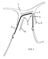
- a pair of spectacles according to the invention consists of a spectacle frame 1 for two spectacle lenses with a glass holder for each of the two spectacle lenses by means of a thread of high tensile and low elasticity generating the holding forces, the ends of which are fixed directly to the spectacle frame 1 or in a spectacle lens to simplify the understanding in the figures to the different embodiments similar basic components are provided with the same reference numerals.
- All figures is equal to a molded from thin titanium sheet spectacle frame 1 with at least the lenses on their upper sides receiving edges with a connecting this connecting web, the variants of the in the Fig. 1 to 5 and 10 to 12 illustrated spectacle frames 1 respectively from a plane of the titanium sheet 1 inwardly or to the face of a spectacle wearer bent projections 5, which are formed as Nasenhoffl 6 and form on their upwardly directed end faces ramps 7, over which a thread 2 can be pushed , where this rests directly on the inside of the spectacle frame 1 and engaged in receiving grooves 4 of the projections 5, which holds spectacle lenses in the spectacle frame.
- the projections 5 thus form the tensioning device for the thread 2, which is deflected around the projections 5.
- the nostrils 6 can, as in the Fig. 3 and 5 is clarified, be designed differently sized or, as in the Fig. 7 and 9 is shown, also missing completely.
- a projection 5, as well as the nosepiece 6 in the Fig. 1 to 5 be integrally formed on the spectacle frame 1, here for each spectacle lens but as a short, a groove forming section with a receiving groove 4, in which the thread 2 must be inserted to achieve the required voltage.
- An embodiment of the spectacle frame 1, as in the 8 and 9 is shown, is equipped with a separate holding part 15 which is inserted from the front through an opening 16 in the spectacle frame 1 through and forms a back projection 5, with a receiving groove 4 for the thread 2 and an upward, the ramp. 7 forming end face over which the thread 2 must be moved to produce the elastic clamping force.
- the 10 to 12 show different spectacle frames 1, where in the Fig. 10 a single thread 2 is fixed to the lateral outer regions of the spectacle frame 1 which comprises the spectacle lenses along their underside and is guided over the tensioning device 3 in the region of the bridge web of the spectacle frame 1.
- the spectacle frame 1 of Fig. 11 has on the left side a further attachment variant of the thread 2 in the spectacle lens, and in each case a thread 2 per spectacle lens to illustrate that the inventive glass holder is also suitable for attachment of individual spectacle lenses.
- the spectacle frame 1 of Fig. 12 shows again, similar to the 4 and 5 , a spectacle frame 1, which almost completely surrounds the lenses and in which the thread 2 essentially serves to brace the converging parts of the spectacle frame 1 in the nose region against one another in order to ensure the firm hold of the spectacle lenses in the spectacle frame 1.
Landscapes
- Physics & Mathematics (AREA)
- Health & Medical Sciences (AREA)
- General Physics & Mathematics (AREA)
- Ophthalmology & Optometry (AREA)
- Optics & Photonics (AREA)
- Eyeglasses (AREA)
Abstract
Description
- Die Erfindung betrifft eine Brillenfassung für zwei Brillengläser, aus einer Glashalterung für jedes der beiden Brillengläser, mit einem Haltekräfte erzeugenden Faden hoher Zug- und geringer Dehnfähigkeit, dessen Enden am Gestell oder im Randbereich eines Brillenglases festgelegt sind.
- Solche Brillengestelle sind beispielsweise aus der
DE 27 15 755 A1 bekannt, die zwei Fassungen für zwei Brillengläser aufweisen sowie zwei Fäden, die jeweils die untere Hälfte des Umfangs eines Brillenglases umfassen und an den Enden an den Fassungen festgelegt sind. - Nachteilig an diesem bekannten Brillengestell ist, dass die Fäden einen V-förmigen bzw. einen keilnutartigen Querschnitt sowie als Spannwülste ausgebildete Enden aufweisen müssen, so dass zur Variation von Glasgrößen unterschiedlich lange Fäden vorgehalten werden müssen, ebenso wie die Montage und Demontage der Brillengläser eine erhöhte Aufmerksamkeit und gesteigerte handwerkliche Fertigkeit verlangt.
- Aufgabe der Erfindung ist es, eine neuartige Brillenfassung mit einer Glashalterung zur Verfügung zu stellen, die technisch einfachst aufgebaut und des Weiteren leicht zu handhaben ist. Ebenso soll ein einfacher Faden Verwendung finden können, der entsprechend seiner benötigten Länge von einer Rolle abgelängt werden kann.
- Die Lösung dieser Aufgabe ergibt sich in Verbindung mit den Oberbegriffsmerkmalen erfindungsgemäß aus dem kennzeichnenden Teil des ersten Patentanspruchs insbesondere dadurch, dass der Faden ein Längenmaß aufweist, welches größer ist als die tatsächliche Länge zwischen seinen endseitigen Befestigungen und dem Umschlingungsweg um ein Brillenglas und dass an der Brillenfassung eine Spannvorrichtung für den Faden vorgesehen ist. Hierdurch lässt sich ein Brillenglas zunächst ohne Vorspannung in eine Brillenfassung einsetzen, der Faden ggf. in eine Längsausnehmung in den Rand eines Brillenglases einlegen und erst anschließend durch Betätigung der Spannvorrichtung das Brillenglas in der Brillenfassung befestigen.
- Besonders vorteilhaft ist, dass die Befestigung des Fadenendes in bekannter einfacher Art und Weise durch eine oder mehrere Bohrungen in der Brillenfassung oder im Rand des Brillenglases vorgenommen werden kann, wobei der Faden selber aus einem schlichten kreisrunden Nylonfaden bestehen kann, der in der erforderlichen Länge von einer Rolle abgetrennt werden kann. Es müssen demnach für die Fertigung keine unterschiedlich langen Fäden oder Fäden mit einer bestimmten Querschnittsform bereitgehalten werden.
- Die Spannvorrichtung ist dabei so einfach und einsichtig aufgebaut, dass ihre Funktion nicht nur sofort für jeden erkennbar ist, sondern sie lässt sich auch ohne die Verwendung von weiteren Werkzeugen mit den Fingern betätigen. Diese neuartige Glashalterung ist damit höchst einfach und sehr leicht handzuhaben und auch das Lösen eines Brillenglases erfolgt durch einfaches Entspannen der Spannvorrichtung, welches ebenfalls im Wesentlichen ohne die Verwendung von Werkzeugen durchführbar ist. Als einfaches Hilfsmittel kann hier beispielsweise ein dünner Plastikstreifen dienen, der unter den Faden entlang geführt und zu einer Schlaufe geknickt werden kann, über die der Faden mit einer seitlichen Zugkraft beaufschlagt aus der Spannvorrichtung herausgehoben werden kann.
- Weitere vorteilhafte Ausführungen des Gegenstandes der Erfindung ergeben sich mit und in Kombination aus den nachfolgenden Unteransprüchen.
- Gemäß einer besonders bevorzugten Ausführungsform der Erfindung besteht die Spannvorrichtung aus einer einfachen Fadenumlenkung, um die der Faden nach dem Einsetzen eines Glases unter Erzeugung elastischer Haltekräfte herumgelegt wird.
- Die Fadenumlenkung ist dabei besonders einfach herstellbar, da sie aus einem nach innen, zum Gesicht des Brillenträgers hin aus einer Ebene der Brillenfassung hervorstehenden Vorsprung ausgebildet sein kann, wobei in diesem Vorsprung eine Aufnahmenut für den Faden eingebracht ist, damit dieser bei jeder möglichen Beanspruchung der Brillenfassung in der Spannvorrichtung verbleibt.
- Der Vorsprung lässt sich aus dem Grundmaterial der Brillenfassung herstellen, indem er an diese angeformt ist oder bei einer aus einem Metallblech gefertigten Brillenfassung aus deren Ebene nach innen umgefalzt ist, wobei in der oberen Kante des Vorsprunges im Falzbereich auch die Aufnahmenut vorgesehen sein kann. Die auf Grundlage dieser Gestaltungsvariante, der mit der Spannvorrichtung einteiligen Brillenfassung, herstellbaren Ausführungsformen sind extrem vielfältig.
- Bei einer weiteren grundsätzlichen und ebenso vorteilhaften Gestaltungsvariante ist die Brillenfassung mit einem separaten Halteteil ausgestattet ist, welches den Vorsprung zur Verfügung stellt, in dem es beispielsweise von vorne durch eine Durchbrechung in der Brillenfassung in diese eingeführt ist und ein nach innen hervorstehender Absatz des Halteteiles den Vorsprung bildet, der ebenso wieder mit einer Aufnahmenut versehen ist. Hierdurch wird gleichzeitig das separate Halteteil am Herausrutschen aus der Brillenfassung entgegen der Einsteckrichtung verriegelt. Auch diese Gestaltungsvariante erlaubt eine Vielzahl von vorteilhaften Ausführungsformen.
- Von besonderem Vorteil ist weiterhin eine Ausführungsform der Erfindung, bei der die nach innen umgebogenen oder angeformten Teile der aus einem flachen Metallblech gefertigten Brillenfassung Nasenbügel bilden, die vorteilhafterweise so gestaltet sind, dass ihre Oberseiten in Form einer Rampe ausgeführt sind und am Ende der Rampe die Aufnahmenuten eingebracht sind, so dass zur Erzeugung der elastischen Haltekräfte der Faden ohne mechanische Beschädigungen zu erfahren einfach über die Rampen der Nasenbügel bis in die Aufnahmenuten bewegt werden kann, was insbesondere auch ohne die Verwendung von Werkzeug, sozusagen "kinderleicht" ausgeführt werden kann.
- Bei einer besonders vorteilhaften Ausgestaltung des Gegenstandes der Erfindung sind beide Brillengläser von nur einem gemeinsamen Faden in der Brillenfassung festgelegt, wobei die Enden des Fadens in herkömmlicher Art und Weise entweder im Brillenglas oder in zu der Brillenfassung zugehörigen Teilen festgelegt sind und der Faden von einer Spannvorrichtung gehalten ist, die beispielsweise von jeweils zwei Nasenflügeln oder anderen hakenförmigen Aufnahmen der Brillenfassung gebildet werden oder von einer durchgängigen Aufnahme für den Faden zur Verfügung gestellt wird.
- Bei einer bevorzugten Ausführungsform des Gegenstandes der Erfindung erstreckt sich der Faden über einen Großteil des unteren Randes eines Brillenglases und bildet somit selber einen Teil der Glashalterung, wobei bei einer anderen vorteilhaften Ausführungsform der Erfindung der Faden im Wesentlichen dazu dient, die sich nah gegenüberliegenden Bereiche einer ein Brillenglas fast vollständig umschließenden Brillenfassung so gegeneinander zu verspannen, dass ein Brillenglas fest darin gehalten wird.
- Jede denkbare Zwischenlösung mit einem ein Brillenglas oder beide Brillengläser mehr oder weniger umschließenden Faden oder einer mehr oder weniger ein Brillenglas oder die Brillengläser umfassenden Brillenfassung ist hier denkbar, ebenso wie viele unterschiedliche Varianten der Spannvorrichtung konstruktiv verwirklicht werden können, wobei alle eine vollkommen neuartige Glashalterung zur Verfügung stellen, die technisch einfachst ausgeführt und von jedermann leicht zu handhaben ist, sei es beim Befestigen der Brillengläser oder beim Lösen der Glashalterung, welches im Wesentlichen ohne Werkzeuge durchführbar ist.
- Nachfolgend sind einige Beispiele der Erfindung anhand von Zeichnungen näher beschrieben. Es zeigen:
- Fig. 1
- eine räumliche Teilansicht einer Brillenfassung mit einem gleichzeitig zwei Brillengläser haltenden Faden,
- Fig. 2
- eine Teilansicht der Brillenfassung gem.
Fig. 1 , - Fig. 3
- eine geschnittene Seitenansicht der Brillenfassung gem. den
Fig. 1 und2 , - Fig. 4
- eine Teilansicht einer Brillenfassung mit variiertem Nasenbügel,
- Fig. 5
- eine geschnittene Seitenansicht der Brillenfassung gem.
Fig. 4 , - Fig. 6
- eine Teilansicht einer Brillenfassung mit angeformter rinnenförmigen Spannvorrichtung,
- Fig. 7
- eine geschnittene Seitenansicht der Brillenfassung gem.
Fig. 6 , - Fig. 8
- eine Teilansicht einer Brillenfassung mit einer als separatem Bauteil ausgebildeten Spannvorrichtung,
- Fig. 9
- eine geschnittene Seitenansicht der Brillenfassung gem.
Fig. 8 , - Fig. 10
- eine Ansicht einer Brillenfassung mit einem die Unterseiten zweier Brillengläser haltenden einzelnen Faden,
- Fig. 11
- eine Ansicht einer Brillenfassung mit je einem Faden je Brillenglas und variierenden endseitigen Befestigungen des Fadens, und
- Fig. 12
- eine Ansicht einer Brillenfassung mit die Brillengläser fast vollständig umgebenden Fassung und einem diese miteinander verspannenden Faden.
- Eine entsprechend dem Erfindungsgedanken hergestellte Brille besteht aus einer Brillenfassung 1 für zwei Brillengläser mit einer Glashalterung für jedes der beiden Brillengläser mittels eines die Haltekräfte erzeugenden Fadens hoher Zug- und geringer Dehnfähigkeit, dessen Enden unmittelbar an der Brillenfassung 1 oder in einem Brillenglas festgelegt sind, wobei zur Vereinfachung des Verständnisses in den Figuren zu den unterschiedlichen Ausführungsformen ähnliche Grundbauteile mit den selben Bezugsziffern versehen sind.
- Allen Figuren gleich ist eine aus dünnem Titanblech ausgeformte Brillenfassung 1 mit zumindest die Brillengläser an ihren Oberseiten aufnehmenden Rändern mit einem diese verbindenden Verbindungssteg, wobei die Varianten der in den
Fig. 1 bis 5 und10 bis 12 dargestellten Brillenfassungen 1 jeweils aus einer Ebene des Titanbleches 1 nach innen bzw. zum Gesicht eines Brillenträgers hin umgebogene Vorsprünge 5 aufweist, die als Nasenflügel 6 ausgebildet sind und die an ihren nach oben gerichteten Stirnseiten Rampen 7 bilden, über die ein Faden 2 aufgeschoben werden kann, wo dieser unmittelbar von innen an der Brillenfassung 1 anliegt und in Aufnahmenuten 4 der Vorsprünge 5 eingerastet, die Brillengläser in der Brillenfassung hält. - Die Vorsprünge 5 bilden somit die Spannvorrichtung für den Faden 2, der um die Vorsprünge 5 umgelenkt ist. Die Nasenflügel 6 können, wie in den
Fig. 3 und5 verdeutlicht ist, unterschiedlich groß ausgebildet sein oder, wie in denFig. 7 und9 gezeigt ist, auch ganz fehlen. - Wie in den
Fig. 6 und 7 dargestellt ist, kann ein Vorsprung 5, wie auch die Nasenbügel 6 in denFig. 1 bis 5 , einteilig an der Brillenfassung 1 angeformt sein, hier für jedes Brillenglas jedoch als kurzer, eine Rinne bildender Abschnitt mit einer Aufnahmenut 4, in die der Faden 2 eingelegt werden muss, um die erforderliche Spannung zu erzielen. - Eine Ausführungsform der Brillenfassung 1, wie sie in den
Fig. 8 und 9 dargestellt ist, ist mit einem separaten Halteteil 15 ausgestattet, welches von vorne durch eine Durchbrechung 16 in der Brillenfassung 1 hindurch gesteckt ist und nach hinten einen Vorsprung 5 bildet, mit einer Aufnahmenut 4 für den Faden 2 und einer nach oben gerichteten, die Rampe 7 bildenden Stirnseite, über die der Faden 2 zur Erzeugung der elastischen Spannkraft bewegt werden muss. - Die
Fig. 10 bis 12 zeigen unterschiedliche Brillenfassungen 1, wobei in derFig. 10 ein einzelner Faden 2 an den seitlichen Außenbereichen der Brillenfassung 1 festgelegt ist der die Brillengläser entlang ihrer Unterseite umfasst und im Bereich des Brückensteges der Brillenfassung 1 über die Spannvorrichtung 3 geführt ist. Die Brillenfassung 1 derFig. 11 weist auf der linken Seite eine weitere Befestigungsvariante des Fadens 2 im Brillenglas auf, sowie jeweils einen Faden 2 je Brillenglas, um darzustellen, dass die erfinderische Glashalterung sich ebenfalls zur Befestigung einzelner Brillengläser eignet. - Das Brillengestell 1 der
Fig. 12 zeigt nochmals, ähnlich wie dieFig. 4 und 5 , eine Brillenfassung 1, die die Brillengläser fast vollständig umgibt und bei denen der Faden 2 im Wesentlichen dazu dient, die im Nasenbereich aufeinander zulaufenden Teile der Brillenfassung 1 gegeneinander zu verspannen, um den festen Halt der Brillengläser in der Brillenfassung 1 zu gewährleisten.
Claims (14)
- Brillenfassung für zwei Brillengläser, aus einer Glashalterung für jedes der beiden Brillengläser mit einem Haltekräfte erzeugenden Faden (2) hoher Zug- und geringer Dehnfähigkeit, dessen Enden am Gestell oder an einem Brillenglas festgelegt sind, dadurch gekennzeichnet, dass der Faden (2) ein Längenmaß aufweist, welches größer ist als die tatsächlich Länge zwischen seiner endseitigen Befestigung und dem Umschlingungsweg um ein Brillenglas und dass an der Brillenfassung (1) eine Spannvorrichtung (3) für den Faden (2) vorgesehen ist.
- Brillenfassung nach Anspruch 1, dadurch gekennzeichnet, dass die Spannvorrichtung (3) aus einer Fadenumlenkung besteht, um die der Faden (2) nach dem Einsetzen eines Glases unter Erzeugung elastischer Haltekräfte herumgelegt ist.
- Brillenfassung nach einem der vorgenannten Ansprüche, dadurch gekennzeichnet, dass die Fadenumlenkung eine Aufnahmenut (4) für den Faden (2) aufweist.
- Brillenfassung nach einem der vorgenannten Ansprüche, dadurch gekennzeichnet, dass die Fadenumlenkung aus mindestens einem nach innen, zum Gesicht des Brillenträgers hin aus einer Ebene der Brillefifassung (1) hervorstehenden Vorsprung (5) ausgebildet ist.
- Brillenfassung nach Anspruch 4, dadurch gekennzeichnet, dass der Vorsprung (5) einteilig an dem Brillenfassung (1) angeformt ist.
- Brillenfassung nach Anspruch 4, dadurch gekennzeichnet, dass der Vorsprung (5) als separates, an der Brillenfassung (1) festgelegtes Halteteil (15) ausgebildet ist.
- Brillenfassung nach Anspruch 6, dadurch gekennzeichnet, dass in der Brillenfassung (1) eine Durchbrechung (16) vorgesehen ist, durch die sich das separate Halteteil (15) von außen nach innen erstreckt, welches einen frei nach innen hin hervorstehenden Vorsprung (5) aufweist, der mit der Aufnahmenut (4) versehen ist.
- Brillenfassung nach Anspruch 4, dadurch gekennzeichnet, dass sie aus einer dünnen Platte, wie aus Metall oder Kunststoff ausgestanzt ist, und Nasenbügel (6) nach innen umgefalzt sind, wobei die oberen Kanten der Nasenbügel (6) im Falzbereich mit den Aufnahmenuten (4) versehen sind.
- Brillenfassung nach Anspruch 8, dadurch gekennzeichnet, dass der Nasenbügel (6) auf derjenigen Seite, über die ein freier Abschnitt des Fadens (2) zur Erzeugung der elastischen Haltekräfte schiebbar ist, die Form einer Rampe (7) aufweist und am Ende der Rampe (7) die Aufnahmenut (4) eingebracht ist.
- Brillenfassung nach einem der vorgenannten Ansprüche, dadurch gekennzeichnet, dass beide Brillengläser von nur einem gemeinsamen Faden (4) in der Brillenfassung (1) festgelegt sind.
- Brillenfassung nach einem der vorgenannten Ansprüche, dadurch gekennzeichnet, dass für jedes Brillenglas eine Fadenumlenkung an der Brillenfassung (1) vorgesehen ist.
- Brillenfassung nach einem der vorgenannten Ansprüche, dadurch gekennzeichnet, dass der Faden (4) selber einen Teil der Glashalterung bildet und ein Glas oder beide Gläser teilweise umspannt.
- Brillenfassung nach einem der vorgenannten Ansprüche 1 bis 11, dadurch gekennzeichnet, dass der Faden (4) der Glashalterung dienenden Teile der Brillenfassung (1) gegeneinander verspannt.
- Brillenfassung nach Anspruch 12 und 13, dadurch gekennzeichnet, dass der Faden (4) die Brillengläser teilweise umspannt und teilweise der Glashalterung dienenden Teile der Brillenfassung (1) gegeneinander verspannt.
Applications Claiming Priority (1)
| Application Number | Priority Date | Filing Date | Title |
|---|---|---|---|
| DE200910005633 DE102009005633A1 (de) | 2009-01-21 | 2009-01-21 | Brillenfassung |
Publications (3)
| Publication Number | Publication Date |
|---|---|
| EP2211225A1 true EP2211225A1 (de) | 2010-07-28 |
| EP2211225B1 EP2211225B1 (de) | 2013-04-17 |
| EP2211225B8 EP2211225B8 (de) | 2013-07-03 |
Family
ID=41615592
Family Applications (1)
| Application Number | Title | Priority Date | Filing Date |
|---|---|---|---|
| EP20090014859 Active EP2211225B8 (de) | 2009-01-21 | 2009-12-01 | Brillenfassung |
Country Status (3)
| Country | Link |
|---|---|
| EP (1) | EP2211225B8 (de) |
| DE (1) | DE102009005633A1 (de) |
| DK (1) | DK2211225T3 (de) |
Cited By (1)
| Publication number | Priority date | Publication date | Assignee | Title |
|---|---|---|---|---|
| EP2857889A3 (de) * | 2013-09-12 | 2015-06-24 | Markus Temming Holding GmbH, | Brillenbügelscharnier |
Citations (5)
| Publication number | Priority date | Publication date | Assignee | Title |
|---|---|---|---|---|
| DE2715755A1 (de) | 1976-08-05 | 1978-02-09 | Hoya Lens Corp | Brillengestell |
| EP0096112B1 (de) * | 1982-06-08 | 1986-07-16 | OPTYL HOLDING GMBH & CO. VERWALTUNGS-KG | Brille mit auswechselbaren Sichtscheiben |
| WO1995018986A1 (fr) | 1994-01-07 | 1995-07-13 | Px Holding S.A. | Lunettes et leur procede de fabrication |
| EP0896112A1 (de) | 1997-08-05 | 1999-02-10 | L'industrielle Regionale Du Batiment | Rauchgasrohrelement insbesondere zum Anbringen in einem Dachdurchführungsbereich |
| US20010017686A1 (en) | 2000-02-28 | 2001-08-30 | Isao Hyoi | High-tension thread fastening structure for eyeglasses frame |
Family Cites Families (4)
| Publication number | Priority date | Publication date | Assignee | Title |
|---|---|---|---|---|
| US1358200A (en) * | 1919-03-31 | 1920-11-09 | Max Siegel | Eyeglasses or spectacles |
| US7104645B2 (en) * | 2002-07-10 | 2006-09-12 | Pilat Jr James F | Eyeglass frame assembly |
| DE20300607U1 (de) * | 2003-01-10 | 2003-04-10 | Concave-Optic GmbH, 75323 Bad Wildbad | Brillenfassung |
| US7063420B2 (en) * | 2004-05-14 | 2006-06-20 | Isl Technologies, Llc | Adjustable tensioning system for rimless eyewear |
-
2009
- 2009-01-21 DE DE200910005633 patent/DE102009005633A1/de not_active Ceased
- 2009-12-01 EP EP20090014859 patent/EP2211225B8/de active Active
- 2009-12-01 DK DK09014859T patent/DK2211225T3/da active
Patent Citations (5)
| Publication number | Priority date | Publication date | Assignee | Title |
|---|---|---|---|---|
| DE2715755A1 (de) | 1976-08-05 | 1978-02-09 | Hoya Lens Corp | Brillengestell |
| EP0096112B1 (de) * | 1982-06-08 | 1986-07-16 | OPTYL HOLDING GMBH & CO. VERWALTUNGS-KG | Brille mit auswechselbaren Sichtscheiben |
| WO1995018986A1 (fr) | 1994-01-07 | 1995-07-13 | Px Holding S.A. | Lunettes et leur procede de fabrication |
| EP0896112A1 (de) | 1997-08-05 | 1999-02-10 | L'industrielle Regionale Du Batiment | Rauchgasrohrelement insbesondere zum Anbringen in einem Dachdurchführungsbereich |
| US20010017686A1 (en) | 2000-02-28 | 2001-08-30 | Isao Hyoi | High-tension thread fastening structure for eyeglasses frame |
Cited By (1)
| Publication number | Priority date | Publication date | Assignee | Title |
|---|---|---|---|---|
| EP2857889A3 (de) * | 2013-09-12 | 2015-06-24 | Markus Temming Holding GmbH, | Brillenbügelscharnier |
Also Published As
| Publication number | Publication date |
|---|---|
| EP2211225B8 (de) | 2013-07-03 |
| DK2211225T3 (da) | 2013-07-22 |
| EP2211225B1 (de) | 2013-04-17 |
| DE102009005633A1 (de) | 2010-07-29 |
Similar Documents
| Publication | Publication Date | Title |
|---|---|---|
| DE3134992C2 (de) | Brillengestell | |
| EP3244847B1 (de) | Vorrichtung zur nagelkorrektur | |
| DE3227813C2 (de) | Brillengestell mit abnehmbarem Fassungsteil | |
| EP1877853B1 (de) | Vorrichtung zum wechseln von bügeln, backen und steg für randlosbrillen sowie von bügeln und backen für metall- und kunststoff-brillengestelle | |
| EP2840978A1 (de) | Einteiliger chirurgischer clip | |
| EP2730688A1 (de) | Weblitze vorzugsweise zum Verarbeiten von bandförmigem Material und Verfahren zum Herstellen derselben | |
| EP0232462B1 (de) | Bügel für eine Brille | |
| WO2011107410A1 (de) | Brille | |
| EP2211225B1 (de) | Brillenfassung | |
| WO1997019384A1 (de) | Randloser vorhänger für brillen | |
| DE3413827C2 (de) | Brille mit Brillengläsern ohne Einfassung und ohne Tragebalken | |
| EP2851736A1 (de) | Brillenbügel | |
| DE2906516A1 (de) | Brillenscharnier | |
| DE102012111073B4 (de) | Vorrichtung zum Wechseln von Backen oder Backenbügeln eines Brillengestells | |
| EP1992779A2 (de) | Auszugsprofil für Fensterblende | |
| EP1820415B1 (de) | Vorrichtung zum Verbinden eines Endteils eines Bandes mit einem weiteren Teil | |
| DE102023116829B3 (de) | Brille | |
| WO2017121807A1 (de) | Vorrichtung zur befestigung eines bügels, einer backe und/oder einer brücke eines brillengestells an einem brillenglas einer randlosbrille | |
| DE9113044U1 (de) | Konstruktionsprofil mit einer Einrichtung zum Eingriff und zum Einsatz einer kraftschlüssigen Verbindung mit einem anderen, parallelverlaufenden Konstruktionsprofil, insbesondere für flexible Montagesysteme | |
| AT521327B1 (de) | Brillengestell | |
| DE8802518U1 (de) | Brille | |
| EP2177807A2 (de) | Bandschelle | |
| EP3419845A1 (de) | Kraftfahrzeuganordnung, vormontageeinheit, profilleiste und verfahren zur montage einer kraftfahrzeuganordnung | |
| EP1312316A2 (de) | Fixationselement zur Herstellung einer Fixationsverbindung auseinandergebrochener Knochenteile | |
| DE2450476B2 (de) | Brillengestell mit mindestens einer loesbaren verbindung, insbesondere gelenkverbindung, zwischen je zwei teilen des brillengestells |
Legal Events
| Date | Code | Title | Description |
|---|---|---|---|
| PUAI | Public reference made under article 153(3) epc to a published international application that has entered the european phase |
Free format text: ORIGINAL CODE: 0009012 |
|
| AK | Designated contracting states |
Kind code of ref document: A1 Designated state(s): AT BE BG CH CY CZ DE DK EE ES FI FR GB GR HR HU IE IS IT LI LT LU LV MC MK MT NL NO PL PT RO SE SI SK SM TR |
|
| AX | Request for extension of the european patent |
Extension state: AL BA RS |
|
| 17P | Request for examination filed |
Effective date: 20101209 |
|
| 17Q | First examination report despatched |
Effective date: 20110413 |
|
| GRAP | Despatch of communication of intention to grant a patent |
Free format text: ORIGINAL CODE: EPIDOSNIGR1 |
|
| GRAS | Grant fee paid |
Free format text: ORIGINAL CODE: EPIDOSNIGR3 |
|
| GRAA | (expected) grant |
Free format text: ORIGINAL CODE: 0009210 |
|
| RAP1 | Party data changed (applicant data changed or rights of an application transferred) |
Owner name: MARKUS TEMMING HOLDING GMBH, |
|
| RIN1 | Information on inventor provided before grant (corrected) |
Inventor name: MARKUS TEMMING |
|
| AK | Designated contracting states |
Kind code of ref document: B1 Designated state(s): AT BE BG CH CY CZ DE DK EE ES FI FR GB GR HR HU IE IS IT LI LT LU LV MC MK MT NL NO PL PT RO SE SI SK SM TR |
|
| REG | Reference to a national code |
Ref country code: GB Ref legal event code: FG4D Free format text: NOT ENGLISH |
|
| REG | Reference to a national code |
Ref country code: CH Ref legal event code: EP |
|
| REG | Reference to a national code |
Ref country code: IE Ref legal event code: FG4D Free format text: LANGUAGE OF EP DOCUMENT: GERMAN |
|
| REG | Reference to a national code |
Ref country code: AT Ref legal event code: REF Ref document number: 607642 Country of ref document: AT Kind code of ref document: T Effective date: 20130515 |
|
| REG | Reference to a national code |
Ref country code: DE Ref legal event code: R096 Ref document number: 502009006860 Country of ref document: DE Effective date: 20130613 |
|
| REG | Reference to a national code |
Ref country code: DK Ref legal event code: T3 |
|
| REG | Reference to a national code |
Ref country code: NL Ref legal event code: T3 |
|
| REG | Reference to a national code |
Ref country code: LT Ref legal event code: MG4D |
|
| PG25 | Lapsed in a contracting state [announced via postgrant information from national office to epo] |
Ref country code: LT Free format text: LAPSE BECAUSE OF FAILURE TO SUBMIT A TRANSLATION OF THE DESCRIPTION OR TO PAY THE FEE WITHIN THE PRESCRIBED TIME-LIMIT Effective date: 20130417 Ref country code: FI Free format text: LAPSE BECAUSE OF FAILURE TO SUBMIT A TRANSLATION OF THE DESCRIPTION OR TO PAY THE FEE WITHIN THE PRESCRIBED TIME-LIMIT Effective date: 20130417 Ref country code: IS Free format text: LAPSE BECAUSE OF FAILURE TO SUBMIT A TRANSLATION OF THE DESCRIPTION OR TO PAY THE FEE WITHIN THE PRESCRIBED TIME-LIMIT Effective date: 20130817 Ref country code: SI Free format text: LAPSE BECAUSE OF FAILURE TO SUBMIT A TRANSLATION OF THE DESCRIPTION OR TO PAY THE FEE WITHIN THE PRESCRIBED TIME-LIMIT Effective date: 20130417 Ref country code: PT Free format text: LAPSE BECAUSE OF FAILURE TO SUBMIT A TRANSLATION OF THE DESCRIPTION OR TO PAY THE FEE WITHIN THE PRESCRIBED TIME-LIMIT Effective date: 20130819 Ref country code: GR Free format text: LAPSE BECAUSE OF FAILURE TO SUBMIT A TRANSLATION OF THE DESCRIPTION OR TO PAY THE FEE WITHIN THE PRESCRIBED TIME-LIMIT Effective date: 20130718 Ref country code: ES Free format text: LAPSE BECAUSE OF FAILURE TO SUBMIT A TRANSLATION OF THE DESCRIPTION OR TO PAY THE FEE WITHIN THE PRESCRIBED TIME-LIMIT Effective date: 20130728 Ref country code: SE Free format text: LAPSE BECAUSE OF FAILURE TO SUBMIT A TRANSLATION OF THE DESCRIPTION OR TO PAY THE FEE WITHIN THE PRESCRIBED TIME-LIMIT Effective date: 20130417 Ref country code: NO Free format text: LAPSE BECAUSE OF FAILURE TO SUBMIT A TRANSLATION OF THE DESCRIPTION OR TO PAY THE FEE WITHIN THE PRESCRIBED TIME-LIMIT Effective date: 20130717 |
|
| PG25 | Lapsed in a contracting state [announced via postgrant information from national office to epo] |
Ref country code: BG Free format text: LAPSE BECAUSE OF FAILURE TO SUBMIT A TRANSLATION OF THE DESCRIPTION OR TO PAY THE FEE WITHIN THE PRESCRIBED TIME-LIMIT Effective date: 20130717 Ref country code: PL Free format text: LAPSE BECAUSE OF FAILURE TO SUBMIT A TRANSLATION OF THE DESCRIPTION OR TO PAY THE FEE WITHIN THE PRESCRIBED TIME-LIMIT Effective date: 20130417 Ref country code: HR Free format text: LAPSE BECAUSE OF FAILURE TO SUBMIT A TRANSLATION OF THE DESCRIPTION OR TO PAY THE FEE WITHIN THE PRESCRIBED TIME-LIMIT Effective date: 20130417 Ref country code: CY Free format text: LAPSE BECAUSE OF FAILURE TO SUBMIT A TRANSLATION OF THE DESCRIPTION OR TO PAY THE FEE WITHIN THE PRESCRIBED TIME-LIMIT Effective date: 20130417 Ref country code: LV Free format text: LAPSE BECAUSE OF FAILURE TO SUBMIT A TRANSLATION OF THE DESCRIPTION OR TO PAY THE FEE WITHIN THE PRESCRIBED TIME-LIMIT Effective date: 20130417 |
|
| PG25 | Lapsed in a contracting state [announced via postgrant information from national office to epo] |
Ref country code: CZ Free format text: LAPSE BECAUSE OF FAILURE TO SUBMIT A TRANSLATION OF THE DESCRIPTION OR TO PAY THE FEE WITHIN THE PRESCRIBED TIME-LIMIT Effective date: 20130417 Ref country code: SK Free format text: LAPSE BECAUSE OF FAILURE TO SUBMIT A TRANSLATION OF THE DESCRIPTION OR TO PAY THE FEE WITHIN THE PRESCRIBED TIME-LIMIT Effective date: 20130417 Ref country code: EE Free format text: LAPSE BECAUSE OF FAILURE TO SUBMIT A TRANSLATION OF THE DESCRIPTION OR TO PAY THE FEE WITHIN THE PRESCRIBED TIME-LIMIT Effective date: 20130417 |
|
| PLBE | No opposition filed within time limit |
Free format text: ORIGINAL CODE: 0009261 |
|
| STAA | Information on the status of an ep patent application or granted ep patent |
Free format text: STATUS: NO OPPOSITION FILED WITHIN TIME LIMIT |
|
| PG25 | Lapsed in a contracting state [announced via postgrant information from national office to epo] |
Ref country code: RO Free format text: LAPSE BECAUSE OF FAILURE TO SUBMIT A TRANSLATION OF THE DESCRIPTION OR TO PAY THE FEE WITHIN THE PRESCRIBED TIME-LIMIT Effective date: 20130417 |
|
| 26N | No opposition filed |
Effective date: 20140120 |
|
| REG | Reference to a national code |
Ref country code: DE Ref legal event code: R097 Ref document number: 502009006860 Country of ref document: DE Effective date: 20140120 |
|
| BERE | Be: lapsed |
Owner name: TEMMING HOLDING GMBH, Effective date: 20131231 |
|
| GBPC | Gb: european patent ceased through non-payment of renewal fee |
Effective date: 20131201 |
|
| PG25 | Lapsed in a contracting state [announced via postgrant information from national office to epo] |
Ref country code: MC Free format text: LAPSE BECAUSE OF FAILURE TO SUBMIT A TRANSLATION OF THE DESCRIPTION OR TO PAY THE FEE WITHIN THE PRESCRIBED TIME-LIMIT Effective date: 20130417 Ref country code: LU Free format text: LAPSE BECAUSE OF FAILURE TO SUBMIT A TRANSLATION OF THE DESCRIPTION OR TO PAY THE FEE WITHIN THE PRESCRIBED TIME-LIMIT Effective date: 20131201 |
|
| REG | Reference to a national code |
Ref country code: IE Ref legal event code: MM4A |
|
| PG25 | Lapsed in a contracting state [announced via postgrant information from national office to epo] |
Ref country code: BE Free format text: LAPSE BECAUSE OF NON-PAYMENT OF DUE FEES Effective date: 20131231 Ref country code: IE Free format text: LAPSE BECAUSE OF NON-PAYMENT OF DUE FEES Effective date: 20131201 |
|
| PG25 | Lapsed in a contracting state [announced via postgrant information from national office to epo] |
Ref country code: GB Free format text: LAPSE BECAUSE OF NON-PAYMENT OF DUE FEES Effective date: 20131201 |
|
| PG25 | Lapsed in a contracting state [announced via postgrant information from national office to epo] |
Ref country code: SM Free format text: LAPSE BECAUSE OF FAILURE TO SUBMIT A TRANSLATION OF THE DESCRIPTION OR TO PAY THE FEE WITHIN THE PRESCRIBED TIME-LIMIT Effective date: 20130417 |
|
| PG25 | Lapsed in a contracting state [announced via postgrant information from national office to epo] |
Ref country code: HU Free format text: LAPSE BECAUSE OF FAILURE TO SUBMIT A TRANSLATION OF THE DESCRIPTION OR TO PAY THE FEE WITHIN THE PRESCRIBED TIME-LIMIT; INVALID AB INITIO Effective date: 20091201 Ref country code: MK Free format text: LAPSE BECAUSE OF FAILURE TO SUBMIT A TRANSLATION OF THE DESCRIPTION OR TO PAY THE FEE WITHIN THE PRESCRIBED TIME-LIMIT Effective date: 20130417 |
|
| PG25 | Lapsed in a contracting state [announced via postgrant information from national office to epo] |
Ref country code: MT Free format text: LAPSE BECAUSE OF FAILURE TO SUBMIT A TRANSLATION OF THE DESCRIPTION OR TO PAY THE FEE WITHIN THE PRESCRIBED TIME-LIMIT Effective date: 20130417 |
|
| REG | Reference to a national code |
Ref country code: FR Ref legal event code: PLFP Year of fee payment: 7 |
|
| REG | Reference to a national code |
Ref country code: AT Ref legal event code: MM01 Ref document number: 607642 Country of ref document: AT Kind code of ref document: T Effective date: 20141201 |
|
| PG25 | Lapsed in a contracting state [announced via postgrant information from national office to epo] |
Ref country code: AT Free format text: LAPSE BECAUSE OF NON-PAYMENT OF DUE FEES Effective date: 20141201 |
|
| REG | Reference to a national code |
Ref country code: FR Ref legal event code: PLFP Year of fee payment: 8 |
|
| REG | Reference to a national code |
Ref country code: FR Ref legal event code: PLFP Year of fee payment: 9 |
|
| PGFP | Annual fee paid to national office [announced via postgrant information from national office to epo] |
Ref country code: TR Payment date: 20231123 Year of fee payment: 15 |
|
| REG | Reference to a national code |
Ref country code: CH Ref legal event code: U11 Free format text: ST27 STATUS EVENT CODE: U-0-0-U10-U11 (AS PROVIDED BY THE NATIONAL OFFICE) Effective date: 20260101 |
|
| PGFP | Annual fee paid to national office [announced via postgrant information from national office to epo] |
Ref country code: DK Payment date: 20251217 Year of fee payment: 17 |
|
| PGFP | Annual fee paid to national office [announced via postgrant information from national office to epo] |
Ref country code: NL Payment date: 20251217 Year of fee payment: 17 Ref country code: FR Payment date: 20251218 Year of fee payment: 17 |
|
| PGFP | Annual fee paid to national office [announced via postgrant information from national office to epo] |
Ref country code: DE Payment date: 20251222 Year of fee payment: 17 |
|
| PGFP | Annual fee paid to national office [announced via postgrant information from national office to epo] |
Ref country code: IT Payment date: 20251231 Year of fee payment: 17 |
|
| PGFP | Annual fee paid to national office [announced via postgrant information from national office to epo] |
Ref country code: CH Payment date: 20260101 Year of fee payment: 17 |