EP2210835A1 - Dispositif de séparation à billes d'objets plats - Google Patents
Dispositif de séparation à billes d'objets plats Download PDFInfo
- Publication number
- EP2210835A1 EP2210835A1 EP10150934A EP10150934A EP2210835A1 EP 2210835 A1 EP2210835 A1 EP 2210835A1 EP 10150934 A EP10150934 A EP 10150934A EP 10150934 A EP10150934 A EP 10150934A EP 2210835 A1 EP2210835 A1 EP 2210835A1
- Authority
- EP
- European Patent Office
- Prior art keywords
- flexible bag
- flat objects
- separating
- mail items
- separation
- Prior art date
- Legal status (The legal status is an assumption and is not a legal conclusion. Google has not performed a legal analysis and makes no representation as to the accuracy of the status listed.)
- Granted
Links
- 239000000463 material Substances 0.000 claims abstract description 8
- 239000004677 Nylon Substances 0.000 claims abstract description 4
- 239000000806 elastomer Substances 0.000 claims abstract description 4
- 229920001971 elastomer Polymers 0.000 claims abstract description 4
- 239000011521 glass Substances 0.000 claims abstract description 4
- 229920001778 nylon Polymers 0.000 claims abstract description 4
- 239000004753 textile Substances 0.000 claims abstract description 4
- 239000002184 metal Substances 0.000 claims abstract description 3
- 238000000926 separation method Methods 0.000 claims description 25
- 239000011324 bead Substances 0.000 claims description 5
- 239000000725 suspension Substances 0.000 abstract description 6
- 241000826860 Trapezium Species 0.000 description 4
- 230000006978 adaptation Effects 0.000 description 1
- 230000006835 compression Effects 0.000 description 1
- 238000007906 compression Methods 0.000 description 1
- 230000001627 detrimental effect Effects 0.000 description 1
- 238000010586 diagram Methods 0.000 description 1
- 230000000694 effects Effects 0.000 description 1
- 239000007769 metal material Substances 0.000 description 1
- 238000000034 method Methods 0.000 description 1
- 230000000284 resting effect Effects 0.000 description 1
- 230000000717 retained effect Effects 0.000 description 1
- 238000005303 weighing Methods 0.000 description 1
Images
Classifications
-
- B—PERFORMING OPERATIONS; TRANSPORTING
- B65—CONVEYING; PACKING; STORING; HANDLING THIN OR FILAMENTARY MATERIAL
- B65H—HANDLING THIN OR FILAMENTARY MATERIAL, e.g. SHEETS, WEBS, CABLES
- B65H3/00—Separating articles from piles
- B65H3/46—Supplementary devices or measures to assist separation or prevent double feed
- B65H3/52—Friction retainers acting on under or rear side of article being separated
- B65H3/5207—Non-driven retainers, e.g. movable retainers being moved by the motion of the article
- B65H3/523—Non-driven retainers, e.g. movable retainers being moved by the motion of the article the retainers positioned over articles separated from the bottom of the pile
-
- B—PERFORMING OPERATIONS; TRANSPORTING
- B65—CONVEYING; PACKING; STORING; HANDLING THIN OR FILAMENTARY MATERIAL
- B65H—HANDLING THIN OR FILAMENTARY MATERIAL, e.g. SHEETS, WEBS, CABLES
- B65H1/00—Supports or magazines for piles from which articles are to be separated
- B65H1/04—Supports or magazines for piles from which articles are to be separated adapted to support articles substantially horizontally, e.g. for separation from top of pile
- B65H1/06—Supports or magazines for piles from which articles are to be separated adapted to support articles substantially horizontally, e.g. for separation from top of pile for separation from bottom of pile
-
- B—PERFORMING OPERATIONS; TRANSPORTING
- B65—CONVEYING; PACKING; STORING; HANDLING THIN OR FILAMENTARY MATERIAL
- B65H—HANDLING THIN OR FILAMENTARY MATERIAL, e.g. SHEETS, WEBS, CABLES
- B65H3/00—Separating articles from piles
- B65H3/02—Separating articles from piles using friction forces between articles and separator
- B65H3/04—Endless-belt separators
- B65H3/042—Endless-belt separators separating from the bottom of the pile
-
- B—PERFORMING OPERATIONS; TRANSPORTING
- B65—CONVEYING; PACKING; STORING; HANDLING THIN OR FILAMENTARY MATERIAL
- B65H—HANDLING THIN OR FILAMENTARY MATERIAL, e.g. SHEETS, WEBS, CABLES
- B65H3/00—Separating articles from piles
- B65H3/02—Separating articles from piles using friction forces between articles and separator
- B65H3/06—Rollers or like rotary separators
- B65H3/063—Rollers or like rotary separators separating from the bottom of pile
-
- B—PERFORMING OPERATIONS; TRANSPORTING
- B65—CONVEYING; PACKING; STORING; HANDLING THIN OR FILAMENTARY MATERIAL
- B65H—HANDLING THIN OR FILAMENTARY MATERIAL, e.g. SHEETS, WEBS, CABLES
- B65H2301/00—Handling processes for sheets or webs
- B65H2301/40—Type of handling process
- B65H2301/42—Piling, depiling, handling piles
- B65H2301/423—Depiling; Separating articles from a pile
- B65H2301/4232—Depiling; Separating articles from a pile of horizontal or inclined articles, i.e. wherein articles support fully or in part the mass of other articles in the piles
- B65H2301/42322—Depiling; Separating articles from a pile of horizontal or inclined articles, i.e. wherein articles support fully or in part the mass of other articles in the piles from bottom of the pile
-
- B—PERFORMING OPERATIONS; TRANSPORTING
- B65—CONVEYING; PACKING; STORING; HANDLING THIN OR FILAMENTARY MATERIAL
- B65H—HANDLING THIN OR FILAMENTARY MATERIAL, e.g. SHEETS, WEBS, CABLES
- B65H2701/00—Handled material; Storage means
- B65H2701/10—Handled articles or webs
- B65H2701/19—Specific article or web
- B65H2701/1916—Envelopes and articles of mail
Definitions
- the present invention relates to the field of mail processing and more particularly relates to a device for separating flat objects, such as mail items, used in a franking machine mail items.
- the mail items are generally stacked with mail items of different sizes and weights and thicknesses more or less important, it is necessary to separate one by one to be able to affix a postage stamp.
- this process of separation of mail items is very important to avoid duplicate passages that are highly detrimental because resulting in both a billing (weighing two items instead of one) of one of the two items of mail and a postage of the article below.
- these separation devices are relatively complex with a die mechanism and springs whose adjustment is particularly difficult, especially when it comes to processing mail items at high rates, typically higher at 12,000 envelopes / hour. Indeed, it is necessary to adjust the arrangement, the angle of inclination and the pressure of the die and this regardless of the type of envelopes used, the format, thickness and weight of these envelopes. Indeed, for thin mail items, the force exerted on the die must be important to limit the number of double envelopes while it may be low for mail items of greater thickness. Now, the die being pressed against the mail piece by a compression spring to avoid these double passages, mail items of large thickness, especially those windows, may be damaged or torn.
- the present invention aims to overcome the aforementioned drawbacks by providing a device for separating flat objects such as mail items to separate one by one the flat objects of a stack of flat objects and carry them downstream , characterized in that it comprises at least one flexible bag provided with balls cooperating with at least one drive member for, by its deformation during this transport downstream, separate one by one the flat objects.
- said flexible bag has a parallelepipedal shape trapezoidal section and it may comprise several compartments.
- Said flexible bag may be made of a technical textile material such as nylon.
- said beads have a diameter of less than 10 mm and are made of a material chosen from one of the following: metal, glass, elastomer.
- said drive member comprises at least one series of motorized rollers or at least one motorized belt.
- the present invention also relates to a mailing machine mailing machine feeder comprising a mailpiece separating device as mentioned above.
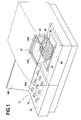
- An automatic mail supply module 12 typically comprises a feed zone formed essentially of a tray 14 for receiving a stack of mail items of different sizes and thicknesses and having first transport rollers 14A for driving these mail items downstream (and against a referencing wall 14B) at a separation zone having a separation device 16 in which these mail items are extracted one by one from the stack of mail items. Second transport rollers (not shown) are generally provided at the exit of this separation zone to convey one by one downstream the mail articles thus extracted.
- Such an automatic feeder is for example illustrated in the European patent EP0 856 483 filed in the name of the plaintiff.
- the device for separating mail items essentially comprises at least one flexible bag 18 provided with a plurality of balls 20 cooperating with a drive member for its deformation during this transport downstream, separate one by one the mail items.
- the flexible bag which has a parallelepipedal shape trapezoidal section is held in position, at the horizontal plane forming the large base of the trapezium, by two suspension arms 22A, 22B extending transversely from a gantry 24. Note that this section trapezoidal allows to find the inclined shape of a conventional selection die.
- the drive member is a simple motorized belt 26 taking almost the entire receiving surface of the mail items.
- the lower portion of the flexible bag 18 (corresponding to the horizontal plane forming the small base of the trapezium) is in direct contact with the motorized belt.
- the marbles are totally free of their movement within this flexible bag and their mobility allows some sort of continuous adaptation depending on the thickness of mail items.
- these beads advantageously have a diameter of less than 10 mm and consist of a metal material, glass or elastomer of sufficient density to allow the separation of mail items.
- the material constituting the flexible bag must have a coefficient of friction with the mail items lower than that existing between the latter and the belt 26, so as not to block the drive.
- the bag may for example be made of a technical textile material such as nylon.
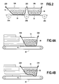
- the transport member consists of three parallel series 28A, 28B, 28C of three motorized rollers and the flexible bag 18 is compartmentalized so that its lower part is not in direct contact with the motorized rollers and therefore subjected to friction ongoing.
- the flexible bag comprises two compartments 18A, 18B held by three suspension arms 22A, 22B, 22C and whose lower parts each rest on the receiving surface 30 of the mail items, one between the first and second rolls of the three sets of rollers and the other between the second and third rolls of these three sets of rollers.
- the first compartment that is in contact with the stack of mail item has a parallelepiped shape trapezoidal section while the second can have a simple rectangular section.
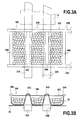
- FIGS 3A and 3B show another example of compartmentalisation of the flexible bag with a drive member comprising two parallel motorized belts 32A, 32B.
- the flexible bag comprises three compartments 18A, 18B, 18C held by four separation bars 34A, 34B, 34C, 34D arranged between the two suspension arms 22A, 22B and whose lower parts each rest on the receiving surface mail items between and on both sides motorized belts.
- These compartments are independent of one another so as not to affect the separation power of each compartment so that the balls can not pass from one compartment to another.
- the flexible bag not being in contact with the drive belts, wear due to permanent friction is limited.
- the Figure 4A illustrates the separation device in its rest position before any separation.
- the mail items 12 of different sizes and thicknesses are arranged on the motorized belt 26 and the flexible bag 22 rests on it. Note its trapezoidal section with the small base of the trapezium resting on the belt 26 and the large base of the trapezium maintained parallel by the suspension arms 22A, 22B.
- the separation has begun and the mailpieces have advanced under the effect of the drive of the motorized belt 26, the one of the bottom having progressed the fastest because of the differential coefficients of friction existing between the belt and the articles of the conveyor belt.
- mail As it moved, the mail item underneath deformed the flexible bag and slid underneath pushing the balls apart and facilitating separation with the next mail item.
- the deformation of the bag is low and the movement of the balls is small while it is more important for items of greater thickness.
- the thick articles are retained very effectively because of the high amount of energy required to move the beads. This energy takes time to be transferred from the training device to the bag, which facilitates the separation.
- thin mail items require less energy but the separation takes place over a greater distance. And the retaining force increases with the length of the path due to the many points of contact with the balls so that these thin mail items are as well separated as the others.
- a simple separation device compact and inexpensive because it has only very few components and especially does not require any adjustment unlike die devices of the prior art.
- it can be implemented with different configurations of drive members, rollers or belts and the constitution of the flexible bag which may comprise one or more compartments arranged between or on these drive members is very flexible.
Landscapes
- Engineering & Computer Science (AREA)
- Mechanical Engineering (AREA)
- Sheets, Magazines, And Separation Thereof (AREA)
- Sorting Of Articles (AREA)
- Cell Separators (AREA)
Abstract
Description
- La présente invention se rapporte au domaine du traitement de courrier et elle concerne plus particulièrement un dispositif de séparation d'objets plats, tels que des articles de courrier, mis en oeuvre dans une machine à affranchir les articles de courrier.
- Dans les machines à affranchir, les articles de courrier se présentent en général par pile avec des articles de courrier de formats et poids différents et d'épaisseurs plus ou moins importantes, qu'il est nécessaire de séparer un à un pour pouvoir y apposer une empreinte postale. Or, ce processus de séparation des articles de courrier est très important pour éviter les doubles passages qui sont forts préjudiciables car entraînant à la fois une sur facturation (pesée de deux articles au lieu d'un seul) de l'un des deux articles de courrier et un non affranchissement de l'article du dessous.
- Aussi, dans les machines à affranchir actuelles, ces dispositifs de séparation sont relativement complexes avec un mécanisme à filière et ressorts dont le réglage est particulièrement délicat, notamment lorsqu'il s'agit de traiter des articles de courrier à des cadences élevées, typiquement supérieure à 12 000 enveloppes/heure. En effet, il est nécessaire de régler la disposition, l'angle d'inclinaison et la pression de la filière et cela quel que soit le type d'enveloppes utilisées, le format, l'épaisseur et le poids de ces enveloppes. En effet, pour les articles de courrier de faible épaisseur, l'effort exercé sur la filière doit être important pour limiter le nombre de doubles enveloppes alors qu'il peut être faible pour les articles de courrier de plus forte épaisseur. Or, la filière étant pressée contre l'article de courrier par un ressort de compression pour éviter ces doubles passages, les articles de courrier de forte épaisseur, et plus particulièrement ceux à fenêtres, risquent d'être endommagés ou déchirés.
- La présente invention a pour but de pallier les inconvénients précités en proposant un dispositif de séparation d'objets plats tels que des articles de courrier pour séparer un à un les objets plats d'une pile d'objets plats et les transporter vers l'aval, caractérisé en ce qu'il comporte au moins un sac flexible muni de billes coopérant avec au moins un organe d'entraînement pour, par sa déformation lors de ce transport vers l'aval, séparer un à un les objets plats.
- Par cette structure simplifiée, on obtient un effort de pression qui s'adapte continûment à l'épaisseur de ces différents objets plats. Lorsque ces objets sont des enveloppes, la qualité de séparation de ces enveloppes quelles soient fines ou épaisses est ainsi grandement améliorée.
- Avantageusement, ledit sac flexible présente une forme parallélépipédique à section trapézoïdale et il peut comporter plusieurs compartiments. Ledit sac flexible peut être réalisé dans un matériau textile technique tel que le nylon.
- De préférence, lesdites billes présentent un diamètre inférieur à 10mm et sont réalisées en un matériau choisi parmi l'un des suivants : métal, verre, élastomère.
- Selon le mode de réalisation envisagé, ledit organe d'entraînement comporte au moins une série de rouleaux motorisés ou au moins une courroie motorisée.
- La présente invention concerne également un alimenteur en articles de courrier pour machine à affranchir comportant un dispositif de séparation d'articles de courrier tel que précité.
- D'autres caractéristiques et avantages de la présente invention ressortiront mieux de la description suivante, faite à titre indicatif et non limitatif, en regard des dessins annexés, sur lesquels :
- la
figure 1 est une vue en perspective d'un alimenteur intégrant un dispositif de séparation d'articles de courrier selon l'invention, - la
figure 2 illustre un deuxième exemple de réalisation du dispositif de séparation d'articles de courrier pouvant être intégré à l'alimenteur de lafigure 1 , - les
figures 3A et 3B sont des vues de face et de dessus d'un troisième exemple de réalisation du dispositif de séparation pouvant être intégré à l'alimenteur de lafigure 1 , et - les
figures 4A et 4B sont des vues en coupe schématiques permettant d'illustrer le fonctionnement du dispositif de séparation selon l'invention. - Un module 10 d'alimentation automatique en articles de courrier 12, tel que celui illustré à la
figure 1 , comporte classiquement une zone d'alimentation formée essentiellement d'un plateau 14 destiné à recevoir une pile d'articles de courrier de différentes tailles et épaisseurs et comportant des premiers rouleaux de transport 14A pour entraîner ces articles de courrier vers l'aval (et contre une paroi de mise en référence 14B) au niveau d'une zone de séparation comportant un dispositif de séparation 16 dans lequel ces articles de courrier sont extraits un par un de la pile d'articles de courrier. Des seconds rouleaux de transport (non représentés) sont en général prévus en sortie de cette zone de séparation pour convoyer un à un vers l'aval les articles de courrier ainsi extraits. Un tel alimenteur automatique est par exemple illustré dans le brevet européenEP0 856 483 déposée au nom de la demanderesse. - Selon l'invention, le dispositif de séparation des articles de courrier comporte essentiellement au moins un sac flexible 18 muni d'une pluralité de billes 20 coopérant avec un organe d'entraînement pour, par sa déformation lors de ce transport vers l'aval, séparer un à un les articles de courrier. Le sac flexible qui présente une forme parallélépipédique à section trapézoïdale est maintenu en position, au niveau du plan horizontal formant la grande base du trapèze, par deux bras de suspension 22A, 22B s'étendant transversalement depuis un portique 24. On notera que cette section trapézoïdale permet de retrouver la forme inclinée d'une filière de sélection classique.
- Sur la
figure 1 , l'organe d'entraînement est une simple courroie motorisée 26 prenant la quasi-totalité de la surface de réception des articles de courrier. La partie inférieure du sac flexible 18 (correspondant au plan horizontal formant la petite base du trapèze) est en contact direct avec la courroie motorisée. Les billes sont totalement libres de leur mouvement à l'intérieur de ce sac flexible et leur mobilité permet en quelque sorte une adaptation continue en fonction de l'épaisseur des articles de courrier. Pour cela, ces billes présentent avantageusement un diamètre inférieur à 10 mm et sont constitués d'un matériau en métal, en verre ou en élastomère d'une densité suffisante pour permettre la séparation des articles de courrier. Bien entendu, le matériau constituant le sac flexible doit présenter un coefficient de friction avec les articles de courrier inférieur à celui existant entre ces derniers et la courroie 26, de façon à ne pas bloquer l'entrainement. Le sac peut par exemple être réalisé dans un matériau textile technique tel que le nylon. - Sur la
figure 2 , l'organe de transport est constitué de trois séries parallèles 28A, 28B, 28C de trois rouleaux motorisés et le sac flexible 18 est compartimenté de sorte que sa partie inférieure ne soit pas en contact direct avec les rouleaux motorisés et donc soumis à une friction continuelle. Plus particulièrement, le sac flexible comporte deux compartiments 18A, 18B maintenus par trois bras de suspension 22A, 22B, 22C et dont les parties inférieures reposent chacune sur la surface de réception 30 des articles de courrier, l'une entre les premiers et deuxièmes rouleaux des trois séries de rouleaux et l'autre entre les deuxièmes et troisièmes rouleaux de ces trois séries de rouleaux. Comme pour la configuration précédente, le premier compartiment qui est en contact avec la pile d'article de courrier présente une forme parallélépipédique à section trapézoïdale alors que le second peut présenter une simple section rectangulaire. - Les
figures 3A et 3B montrent un autre exemple de compartimentage du sac flexible avec un organe d'entraînement comportant deux courroies motorisées parallèles 32A, 32B. Dans cette configuration, le sac flexible comporte trois compartiments 18A, 18B, 18C maintenus par quatre barres de séparation 34A, 34B, 34C, 34D disposées entre les deux bras de suspension 22A, 22B et dont les parties inférieures reposent chacune sur la surface de réception des articles de courrier entre et de part et d'autre des courroies motorisées. Ces compartiments sont indépendants l'un de l'autre pour ne pas affecter le pouvoir de séparation de chaque compartiment de sorte que les billes ne peuvent passer d'un compartiment à l'autre. En outre, le sac flexible n'étant pas en contact avec les courroies d'entraînement, l'usure liée à un frottement permanent est limitée. - Le fonctionnement du dispositif de séparation selon l'invention est maintenant décrit en regard des schémas simplifiés des
figures 4A et 4B . Contrairement à beaucoup de dispositifs de séparation de l'art antérieur, il n'est pas nécessaire de procéder à un tri préalable des articles de courrier en fonction de leur épaisseur, en plaçant les articles de courrier d'épaisseur faible ou standard au dessus, car avec le dispositif de séparation de l'invention, la pression sur les articles de courrier n'est pas fixé au préalable par un réglage prédéterminé mais dépend du poids des billes et est indépendant de la déformation du sac flexible. - La
figure 4A illustre le dispositif de séparation dans sa position de repos avant toute séparation. Les articles de courrier 12 de différents formats et épaisseurs sont disposés sur la courroie motorisée 26 et le sac flexible 22 repose sur lui. On note sa section trapézoïdale avec la petite base du trapèze reposant sur la courroie 26 et la grande base de ce trapèze maintenue parallèlement par les bras de suspension 22A, 22B. Sur lafigure 4B , la séparation a commencé et les articles de courrier ont avancé sous l'effet de l'entrainement de la courroie motorisée 26, celui du dessous ayant progressé le plus rapidement du fait du différentiel des coefficients de friction existant entre la courroie et les articles de courrier. Dans son déplacement, l'article de courrier du dessous a déformé le sac flexible et s'est glissé en dessous repoussant les billes et facilitant ainsi la séparation avec l'article de courrier suivant. - En effet, pour les articles de courrier de faible épaisseur, la déformation du sac est faible et le déplacement des billes est peu important alors qu'il est plus important pour des articles de plus forte épaisseur. Toutefois, les articles de forte épaisseur sont retenus très efficacement du fait de la quantité élevée d'énergie nécessaire pour déplacer les billes. Cette énergie demande du temps pour être transférée de l'organe d'entrainement au sac, ce qui facilite la séparation. Par contre, les articles de courrier de faible épaisseur demandent moins d'énergie mais la séparation s'effectue sur une distance plus importante. Et la force de retenue augmente avec la longueur du trajet du fait des nombreux points de contact avec les billes de sorte que ces articles de courrier de faible épaisseur sont aussi bien séparés que les autres.
- Avec la présente invention, il est proposé un dispositif de séparation simple, compact et peu couteux car il ne comporte que très peu de composants et surtout ne nécessite aucun réglage au contraire des dispositifs à filière de l'art antérieur. En outre, il peut être mis en oeuvre avec différentes configurations d'organes d'entrainement, rouleaux ou courroies et la constitution du sac flexible qui peut comporter un ou plusieurs compartiments disposés entre ou sur ces organes d'entrainement est très souple.
- On aura noté que si l'invention a été décrite préférentiellement en regard d'un alimenteur d'articles de courrier, il est clair que la présente invention peut trouver application dans la séparation de tout autre objet plat que des articles de courrier.
Claims (10)
- Dispositif de séparation d'objets plats pour séparer un à un les objets plats (12) d'une pile d'objets plats et les transporter vers l'aval, caractérisé en ce qu'il comporte au moins un sac flexible (22 ; 22A, 22B, 22C) muni d'une pluralité de billes (24) coopérant avec un organe d'entraînement (26 ; 28A, 28B, 28C ; 32A, 32B) pour, par sa déformation lors de ce transport vers l'aval, séparer un à un lesdits objets plats.
- Dispositif de séparation selon la revendication 1, caractérisé en ce que ledit sac flexible présente une forme parallélépipédique à section trapézoïdale.
- Dispositif de séparation selon la revendication 1, caractérisé en ce que ledit sac flexible comporte plusieurs compartiments (22A, 22B, 22C).
- Dispositif de séparation selon la revendication 1, caractérisé en ce que ledit sac flexible est réalisé dans un matériau textile technique tel que le nylon.
- Dispositif de séparation selon la revendication 1, caractérisé en ce que lesdites billes présentent un diamètre inférieur à 10 mm.
- Dispositif de séparation selon la revendication 5, caractérisé en ce que lesdites billes sont réalisées en un matériau choisi parmi les suivants : métal, verre, élastomère.
- Dispositif de séparation selon la revendication 1, caractérisé en ce que ledit organe d'entraînement comporte au moins une série de rouleaux motorisés (28A, 28B, 28C).
- Dispositif de séparation selon la revendication 1, caractérisé en ce que ledit organe d'entraînement comporte au moins une courroie motorisée (26 ; 32A, 32B).
- Dispositif de séparation selon l'une quelconque des revendications 1 à 8, caractérisé en ce que lesdits objets plats sont des articles de courrier.
- Alimenteur en articles de courrier pour machine à affranchir comportant un dispositif de séparation d'articles de courrier selon la revendication 9.
Applications Claiming Priority (1)
| Application Number | Priority Date | Filing Date | Title |
|---|---|---|---|
| FR0950377A FR2941221A1 (fr) | 2009-01-22 | 2009-01-22 | Dispositif de separation a billes d'objets plats. |
Publications (2)
| Publication Number | Publication Date |
|---|---|
| EP2210835A1 true EP2210835A1 (fr) | 2010-07-28 |
| EP2210835B1 EP2210835B1 (fr) | 2011-11-23 |
Family
ID=40933836
Family Applications (1)
| Application Number | Title | Priority Date | Filing Date |
|---|---|---|---|
| EP10150934A Active EP2210835B1 (fr) | 2009-01-22 | 2010-01-18 | Dispositif de séparation à billes d'objets plats |
Country Status (4)
| Country | Link |
|---|---|
| US (1) | US8205871B2 (fr) |
| EP (1) | EP2210835B1 (fr) |
| AT (1) | ATE534598T1 (fr) |
| FR (1) | FR2941221A1 (fr) |
Families Citing this family (1)
| Publication number | Priority date | Publication date | Assignee | Title |
|---|---|---|---|---|
| JP7156045B2 (ja) * | 2019-01-11 | 2022-10-19 | トヨタ自動車株式会社 | 車両用鋼板の接合構造 |
Citations (4)
| Publication number | Priority date | Publication date | Assignee | Title |
|---|---|---|---|---|
| JPH0445030A (ja) * | 1990-06-11 | 1992-02-14 | Matsushita Graphic Commun Syst Inc | 自動給紙装置 |
| EP0856483A1 (fr) | 1997-01-31 | 1998-08-05 | Neopost Industrie | Dispositif d'alimentation en articles de courrier |
| US20050098940A1 (en) * | 2003-11-06 | 2005-05-12 | James Malatesta | Document separator |
| US20050242487A1 (en) * | 2004-05-03 | 2005-11-03 | Zih Corp. | Feeder device having increased media capacity and multiple media thickness feed capability and associated method |
Family Cites Families (5)
| Publication number | Priority date | Publication date | Assignee | Title |
|---|---|---|---|---|
| US2701662A (en) * | 1951-01-27 | 1955-02-08 | Ernest H Woods Company Inc | Envelope dispensing machine |
| JPS5944236B2 (ja) * | 1977-01-10 | 1984-10-27 | 健司 柘植 | 壁面取付型ホルダ− |
| JP2818963B2 (ja) * | 1990-03-31 | 1998-10-30 | 東海ゴム工業株式会社 | 給紙装置における重送防止用ゴム部材 |
| DE9209615U1 (de) * | 1992-07-17 | 1992-10-22 | Mathias Bäuerle GmbH, 7742 St Georgen | Drehvorrichtung für Papierbogen in einer Förderbahn |
| JP3715943B2 (ja) * | 2002-05-08 | 2005-11-16 | キヤノン株式会社 | 分離部材及びこれを用いたシート給送装置並びに画像処理装置 |
-
2009
- 2009-01-22 FR FR0950377A patent/FR2941221A1/fr active Pending
-
2010
- 2010-01-18 AT AT10150934T patent/ATE534598T1/de active
- 2010-01-18 EP EP10150934A patent/EP2210835B1/fr active Active
- 2010-01-20 US US12/690,666 patent/US8205871B2/en active Active
Patent Citations (4)
| Publication number | Priority date | Publication date | Assignee | Title |
|---|---|---|---|---|
| JPH0445030A (ja) * | 1990-06-11 | 1992-02-14 | Matsushita Graphic Commun Syst Inc | 自動給紙装置 |
| EP0856483A1 (fr) | 1997-01-31 | 1998-08-05 | Neopost Industrie | Dispositif d'alimentation en articles de courrier |
| US20050098940A1 (en) * | 2003-11-06 | 2005-05-12 | James Malatesta | Document separator |
| US20050242487A1 (en) * | 2004-05-03 | 2005-11-03 | Zih Corp. | Feeder device having increased media capacity and multiple media thickness feed capability and associated method |
Also Published As
| Publication number | Publication date |
|---|---|
| ATE534598T1 (de) | 2011-12-15 |
| EP2210835B1 (fr) | 2011-11-23 |
| US20100183421A1 (en) | 2010-07-22 |
| FR2941221A1 (fr) | 2010-07-23 |
| US8205871B2 (en) | 2012-06-26 |
Similar Documents
| Publication | Publication Date | Title |
|---|---|---|
| EP2325120B2 (fr) | Dispositif de sélection d'articles de courrier à doigts multiples pivotants | |
| EP1323653B1 (fr) | Dispositif sélecteur d'articles de courrier | |
| FR2759068A1 (fr) | Dispositif d'alimentation en articles de courrier | |
| EP2413291B1 (fr) | Dispositif de sélection d'articles de courrier en vrac | |
| EP2325808B1 (fr) | Dispositif de sélection d'articles de courrier à leviers perfectionnés | |
| EP2277810B1 (fr) | Dispositif d'alimentation à adhérence améliorée | |
| EP2210835B1 (fr) | Dispositif de séparation à billes d'objets plats | |
| EP2239219B1 (fr) | Dispositif de réception d'articles de courrier à haute capacité | |
| EP2085338B1 (fr) | Dispositif perfectionné de sélection d'articles de courrier | |
| EP2085339B1 (fr) | Dispositif de sélection d'articles de courrier à double filière | |
| EP2085337B1 (fr) | Dispositif de sélection optimisée d'articles de courrier | |
| EP2794131B1 (fr) | Dispositif et procédé d'empilage et de chargement d'objets plats sur chant dans un bac multi-compartiments, machine de tri postal et procédé de tri postal | |
| EP1923340B1 (fr) | Dispositif de chargement automatique d'enveloppes | |
| EP2269929B1 (fr) | Dispositif de chargement automatique à forte capacité | |
| EP3752298A1 (fr) | Installation de tri de courrier avec un convoyeur de bacs et un robot navette manipulateur de bacs | |
| EP2481698A1 (fr) | Dispositif de stockage d'articles de courrier à faible bruit | |
| CA3090209A1 (fr) | Installation de tri de courrier avec un robot navette d'injection de bacs sur convoyeur | |
| EP2481697B1 (fr) | Dispositif de stockage pour machine de traitement de courrier | |
| EP2420462B1 (fr) | Machine de traitement d'objets plats | |
| WO2022079373A1 (fr) | Installation de chargement automatique de sachets dans une boite | |
| EP2041008A1 (fr) | Méthode pour alimenter un dispositif de dépilage d'envois postaux |
Legal Events
| Date | Code | Title | Description |
|---|---|---|---|
| PUAI | Public reference made under article 153(3) epc to a published international application that has entered the european phase |
Free format text: ORIGINAL CODE: 0009012 |
|
| AK | Designated contracting states |
Kind code of ref document: A1 Designated state(s): AT BE BG CH CY CZ DE DK EE ES FI FR GB GR HR HU IE IS IT LI LT LU LV MC MK MT NL NO PL PT RO SE SI SK SM TR |
|
| 17P | Request for examination filed |
Effective date: 20101216 |
|
| GRAP | Despatch of communication of intention to grant a patent |
Free format text: ORIGINAL CODE: EPIDOSNIGR1 |
|
| RIC1 | Information provided on ipc code assigned before grant |
Ipc: B65H 3/04 20060101ALI20110420BHEP Ipc: B65H 3/52 20060101AFI20110420BHEP Ipc: B65H 3/06 20060101ALI20110420BHEP |
|
| GRAS | Grant fee paid |
Free format text: ORIGINAL CODE: EPIDOSNIGR3 |
|
| GRAA | (expected) grant |
Free format text: ORIGINAL CODE: 0009210 |
|
| AK | Designated contracting states |
Kind code of ref document: B1 Designated state(s): AT BE BG CH CY CZ DE DK EE ES FI FR GB GR HR HU IE IS IT LI LT LU LV MC MK MT NL NO PL PT RO SE SI SK SM TR |
|
| REG | Reference to a national code |
Ref country code: GB Ref legal event code: FG4D Free format text: NOT ENGLISH |
|
| REG | Reference to a national code |
Ref country code: CH Ref legal event code: EP |
|
| REG | Reference to a national code |
Ref country code: IE Ref legal event code: FG4D Free format text: LANGUAGE OF EP DOCUMENT: FRENCH |
|
| REG | Reference to a national code |
Ref country code: DE Ref legal event code: R096 Ref document number: 602010000436 Country of ref document: DE Effective date: 20120119 |
|
| REG | Reference to a national code |
Ref country code: NL Ref legal event code: VDEP Effective date: 20111123 |
|
| LTIE | Lt: invalidation of european patent or patent extension |
Effective date: 20111123 |
|
| PG25 | Lapsed in a contracting state [announced via postgrant information from national office to epo] |
Ref country code: NO Free format text: LAPSE BECAUSE OF FAILURE TO SUBMIT A TRANSLATION OF THE DESCRIPTION OR TO PAY THE FEE WITHIN THE PRESCRIBED TIME-LIMIT Effective date: 20120223 Ref country code: IS Free format text: LAPSE BECAUSE OF FAILURE TO SUBMIT A TRANSLATION OF THE DESCRIPTION OR TO PAY THE FEE WITHIN THE PRESCRIBED TIME-LIMIT Effective date: 20120323 Ref country code: LT Free format text: LAPSE BECAUSE OF FAILURE TO SUBMIT A TRANSLATION OF THE DESCRIPTION OR TO PAY THE FEE WITHIN THE PRESCRIBED TIME-LIMIT Effective date: 20111123 |
|
| PG25 | Lapsed in a contracting state [announced via postgrant information from national office to epo] |
Ref country code: GR Free format text: LAPSE BECAUSE OF FAILURE TO SUBMIT A TRANSLATION OF THE DESCRIPTION OR TO PAY THE FEE WITHIN THE PRESCRIBED TIME-LIMIT Effective date: 20120224 Ref country code: SE Free format text: LAPSE BECAUSE OF FAILURE TO SUBMIT A TRANSLATION OF THE DESCRIPTION OR TO PAY THE FEE WITHIN THE PRESCRIBED TIME-LIMIT Effective date: 20111123 Ref country code: HR Free format text: LAPSE BECAUSE OF FAILURE TO SUBMIT A TRANSLATION OF THE DESCRIPTION OR TO PAY THE FEE WITHIN THE PRESCRIBED TIME-LIMIT Effective date: 20111123 Ref country code: NL Free format text: LAPSE BECAUSE OF FAILURE TO SUBMIT A TRANSLATION OF THE DESCRIPTION OR TO PAY THE FEE WITHIN THE PRESCRIBED TIME-LIMIT Effective date: 20111123 Ref country code: PT Free format text: LAPSE BECAUSE OF FAILURE TO SUBMIT A TRANSLATION OF THE DESCRIPTION OR TO PAY THE FEE WITHIN THE PRESCRIBED TIME-LIMIT Effective date: 20120323 Ref country code: SI Free format text: LAPSE BECAUSE OF FAILURE TO SUBMIT A TRANSLATION OF THE DESCRIPTION OR TO PAY THE FEE WITHIN THE PRESCRIBED TIME-LIMIT Effective date: 20111123 Ref country code: LV Free format text: LAPSE BECAUSE OF FAILURE TO SUBMIT A TRANSLATION OF THE DESCRIPTION OR TO PAY THE FEE WITHIN THE PRESCRIBED TIME-LIMIT Effective date: 20111123 |
|
| REG | Reference to a national code |
Ref country code: IE Ref legal event code: FD4D |
|
| PG25 | Lapsed in a contracting state [announced via postgrant information from national office to epo] |
Ref country code: CY Free format text: LAPSE BECAUSE OF FAILURE TO SUBMIT A TRANSLATION OF THE DESCRIPTION OR TO PAY THE FEE WITHIN THE PRESCRIBED TIME-LIMIT Effective date: 20111123 |
|
| BERE | Be: lapsed |
Owner name: NEOPOST TECHNOLOGIES Effective date: 20120131 |
|
| PG25 | Lapsed in a contracting state [announced via postgrant information from national office to epo] |
Ref country code: CZ Free format text: LAPSE BECAUSE OF FAILURE TO SUBMIT A TRANSLATION OF THE DESCRIPTION OR TO PAY THE FEE WITHIN THE PRESCRIBED TIME-LIMIT Effective date: 20111123 Ref country code: SK Free format text: LAPSE BECAUSE OF FAILURE TO SUBMIT A TRANSLATION OF THE DESCRIPTION OR TO PAY THE FEE WITHIN THE PRESCRIBED TIME-LIMIT Effective date: 20111123 Ref country code: BG Free format text: LAPSE BECAUSE OF FAILURE TO SUBMIT A TRANSLATION OF THE DESCRIPTION OR TO PAY THE FEE WITHIN THE PRESCRIBED TIME-LIMIT Effective date: 20120223 Ref country code: IE Free format text: LAPSE BECAUSE OF FAILURE TO SUBMIT A TRANSLATION OF THE DESCRIPTION OR TO PAY THE FEE WITHIN THE PRESCRIBED TIME-LIMIT Effective date: 20111123 Ref country code: EE Free format text: LAPSE BECAUSE OF FAILURE TO SUBMIT A TRANSLATION OF THE DESCRIPTION OR TO PAY THE FEE WITHIN THE PRESCRIBED TIME-LIMIT Effective date: 20111123 Ref country code: DK Free format text: LAPSE BECAUSE OF FAILURE TO SUBMIT A TRANSLATION OF THE DESCRIPTION OR TO PAY THE FEE WITHIN THE PRESCRIBED TIME-LIMIT Effective date: 20111123 |
|
| PG25 | Lapsed in a contracting state [announced via postgrant information from national office to epo] |
Ref country code: RO Free format text: LAPSE BECAUSE OF FAILURE TO SUBMIT A TRANSLATION OF THE DESCRIPTION OR TO PAY THE FEE WITHIN THE PRESCRIBED TIME-LIMIT Effective date: 20111123 Ref country code: PL Free format text: LAPSE BECAUSE OF FAILURE TO SUBMIT A TRANSLATION OF THE DESCRIPTION OR TO PAY THE FEE WITHIN THE PRESCRIBED TIME-LIMIT Effective date: 20111123 Ref country code: IT Free format text: LAPSE BECAUSE OF FAILURE TO SUBMIT A TRANSLATION OF THE DESCRIPTION OR TO PAY THE FEE WITHIN THE PRESCRIBED TIME-LIMIT Effective date: 20111123 Ref country code: MC Free format text: LAPSE BECAUSE OF NON-PAYMENT OF DUE FEES Effective date: 20120131 |
|
| REG | Reference to a national code |
Ref country code: AT Ref legal event code: MK05 Ref document number: 534598 Country of ref document: AT Kind code of ref document: T Effective date: 20111123 |
|
| PLBE | No opposition filed within time limit |
Free format text: ORIGINAL CODE: 0009261 |
|
| STAA | Information on the status of an ep patent application or granted ep patent |
Free format text: STATUS: NO OPPOSITION FILED WITHIN TIME LIMIT |
|
| 26N | No opposition filed |
Effective date: 20120824 |
|
| REG | Reference to a national code |
Ref country code: DE Ref legal event code: R097 Ref document number: 602010000436 Country of ref document: DE Effective date: 20120824 |
|
| PG25 | Lapsed in a contracting state [announced via postgrant information from national office to epo] |
Ref country code: BE Free format text: LAPSE BECAUSE OF NON-PAYMENT OF DUE FEES Effective date: 20120131 |
|
| PG25 | Lapsed in a contracting state [announced via postgrant information from national office to epo] |
Ref country code: AT Free format text: LAPSE BECAUSE OF FAILURE TO SUBMIT A TRANSLATION OF THE DESCRIPTION OR TO PAY THE FEE WITHIN THE PRESCRIBED TIME-LIMIT Effective date: 20111123 |
|
| PG25 | Lapsed in a contracting state [announced via postgrant information from national office to epo] |
Ref country code: MK Free format text: LAPSE BECAUSE OF FAILURE TO SUBMIT A TRANSLATION OF THE DESCRIPTION OR TO PAY THE FEE WITHIN THE PRESCRIBED TIME-LIMIT Effective date: 20111123 |
|
| PG25 | Lapsed in a contracting state [announced via postgrant information from national office to epo] |
Ref country code: ES Free format text: LAPSE BECAUSE OF FAILURE TO SUBMIT A TRANSLATION OF THE DESCRIPTION OR TO PAY THE FEE WITHIN THE PRESCRIBED TIME-LIMIT Effective date: 20120305 |
|
| PG25 | Lapsed in a contracting state [announced via postgrant information from national office to epo] |
Ref country code: FI Free format text: LAPSE BECAUSE OF FAILURE TO SUBMIT A TRANSLATION OF THE DESCRIPTION OR TO PAY THE FEE WITHIN THE PRESCRIBED TIME-LIMIT Effective date: 20111123 |
|
| PG25 | Lapsed in a contracting state [announced via postgrant information from national office to epo] |
Ref country code: MT Free format text: LAPSE BECAUSE OF FAILURE TO SUBMIT A TRANSLATION OF THE DESCRIPTION OR TO PAY THE FEE WITHIN THE PRESCRIBED TIME-LIMIT Effective date: 20111123 |
|
| PG25 | Lapsed in a contracting state [announced via postgrant information from national office to epo] |
Ref country code: TR Free format text: LAPSE BECAUSE OF FAILURE TO SUBMIT A TRANSLATION OF THE DESCRIPTION OR TO PAY THE FEE WITHIN THE PRESCRIBED TIME-LIMIT Effective date: 20111123 |
|
| PG25 | Lapsed in a contracting state [announced via postgrant information from national office to epo] |
Ref country code: SM Free format text: LAPSE BECAUSE OF FAILURE TO SUBMIT A TRANSLATION OF THE DESCRIPTION OR TO PAY THE FEE WITHIN THE PRESCRIBED TIME-LIMIT Effective date: 20111123 Ref country code: LU Free format text: LAPSE BECAUSE OF NON-PAYMENT OF DUE FEES Effective date: 20120118 |
|
| PG25 | Lapsed in a contracting state [announced via postgrant information from national office to epo] |
Ref country code: HU Free format text: LAPSE BECAUSE OF FAILURE TO SUBMIT A TRANSLATION OF THE DESCRIPTION OR TO PAY THE FEE WITHIN THE PRESCRIBED TIME-LIMIT Effective date: 20100118 |
|
| REG | Reference to a national code |
Ref country code: CH Ref legal event code: PL |
|
| PG25 | Lapsed in a contracting state [announced via postgrant information from national office to epo] |
Ref country code: LI Free format text: LAPSE BECAUSE OF NON-PAYMENT OF DUE FEES Effective date: 20140131 Ref country code: CH Free format text: LAPSE BECAUSE OF NON-PAYMENT OF DUE FEES Effective date: 20140131 |
|
| REG | Reference to a national code |
Ref country code: FR Ref legal event code: PLFP Year of fee payment: 7 |
|
| REG | Reference to a national code |
Ref country code: FR Ref legal event code: PLFP Year of fee payment: 8 |
|
| REG | Reference to a national code |
Ref country code: FR Ref legal event code: PLFP Year of fee payment: 9 |
|
| PGFP | Annual fee paid to national office [announced via postgrant information from national office to epo] |
Ref country code: GB Payment date: 20220119 Year of fee payment: 13 Ref country code: DE Payment date: 20220119 Year of fee payment: 13 |
|
| REG | Reference to a national code |
Ref country code: DE Ref legal event code: R082 Ref document number: 602010000436 Country of ref document: DE Representative=s name: CBDL PATENTANWAELTE GBR, DE |
|
| REG | Reference to a national code |
Ref country code: DE Ref legal event code: R119 Ref document number: 602010000436 Country of ref document: DE |
|
| GBPC | Gb: european patent ceased through non-payment of renewal fee |
Effective date: 20230118 |
|
| PG25 | Lapsed in a contracting state [announced via postgrant information from national office to epo] |
Ref country code: GB Free format text: LAPSE BECAUSE OF NON-PAYMENT OF DUE FEES Effective date: 20230118 Ref country code: DE Free format text: LAPSE BECAUSE OF NON-PAYMENT OF DUE FEES Effective date: 20230801 |
|
| PGFP | Annual fee paid to national office [announced via postgrant information from national office to epo] |
Ref country code: FR Payment date: 20250127 Year of fee payment: 16 |