EP2210670B1 - Austragvorrichtung - Google Patents
Austragvorrichtung Download PDFInfo
- Publication number
- EP2210670B1 EP2210670B1 EP09015414.7A EP09015414A EP2210670B1 EP 2210670 B1 EP2210670 B1 EP 2210670B1 EP 09015414 A EP09015414 A EP 09015414A EP 2210670 B1 EP2210670 B1 EP 2210670B1
- Authority
- EP
- European Patent Office
- Prior art keywords
- flow brake
- brake component
- flow
- housing
- discharge device
- Prior art date
- Legal status (The legal status is an assumption and is not a legal conclusion. Google has not performed a legal analysis and makes no representation as to the accuracy of the status listed.)
- Active
Links
- 239000013013 elastic material Substances 0.000 claims description 6
- 238000003860 storage Methods 0.000 claims description 5
- 239000007788 liquid Substances 0.000 claims description 3
- 238000007599 discharging Methods 0.000 claims description 2
- 239000000463 material Substances 0.000 claims description 2
- 230000000717 retained effect Effects 0.000 claims description 2
- 230000000694 effects Effects 0.000 description 17
- 238000011161 development Methods 0.000 description 8
- 230000018109 developmental process Effects 0.000 description 8
- 230000013011 mating Effects 0.000 description 2
- 230000006978 adaptation Effects 0.000 description 1
- 230000015572 biosynthetic process Effects 0.000 description 1
- 230000003247 decreasing effect Effects 0.000 description 1
- 230000001419 dependent effect Effects 0.000 description 1
- 239000006196 drop Substances 0.000 description 1
- 239000003814 drug Substances 0.000 description 1
- 239000003889 eye drop Substances 0.000 description 1
- 229940012356 eye drops Drugs 0.000 description 1
- 238000003754 machining Methods 0.000 description 1
- 238000004519 manufacturing process Methods 0.000 description 1
- 238000000034 method Methods 0.000 description 1
- 230000002093 peripheral effect Effects 0.000 description 1
- 238000005086 pumping Methods 0.000 description 1
- 239000000243 solution Substances 0.000 description 1
- 239000007921 spray Substances 0.000 description 1
Images


Classifications
-
- B—PERFORMING OPERATIONS; TRANSPORTING
- B05—SPRAYING OR ATOMISING IN GENERAL; APPLYING FLUENT MATERIALS TO SURFACES, IN GENERAL
- B05B—SPRAYING APPARATUS; ATOMISING APPARATUS; NOZZLES
- B05B1/00—Nozzles, spray heads or other outlets, with or without auxiliary devices such as valves, heating means
- B05B1/34—Nozzles, spray heads or other outlets, with or without auxiliary devices such as valves, heating means designed to influence the nature of flow of the liquid or other fluent material, e.g. to produce swirl
- B05B1/3402—Nozzles, spray heads or other outlets, with or without auxiliary devices such as valves, heating means designed to influence the nature of flow of the liquid or other fluent material, e.g. to produce swirl to avoid or to reduce turbulencies, e.g. comprising fluid flow straightening means
-
- B—PERFORMING OPERATIONS; TRANSPORTING
- B05—SPRAYING OR ATOMISING IN GENERAL; APPLYING FLUENT MATERIALS TO SURFACES, IN GENERAL
- B05B—SPRAYING APPARATUS; ATOMISING APPARATUS; NOZZLES
- B05B1/00—Nozzles, spray heads or other outlets, with or without auxiliary devices such as valves, heating means
- B05B1/34—Nozzles, spray heads or other outlets, with or without auxiliary devices such as valves, heating means designed to influence the nature of flow of the liquid or other fluent material, e.g. to produce swirl
-
- B—PERFORMING OPERATIONS; TRANSPORTING
- B05—SPRAYING OR ATOMISING IN GENERAL; APPLYING FLUENT MATERIALS TO SURFACES, IN GENERAL
- B05B—SPRAYING APPARATUS; ATOMISING APPARATUS; NOZZLES
- B05B11/00—Single-unit hand-held apparatus in which flow of contents is produced by the muscular force of the operator at the moment of use
- B05B11/0005—Components or details
-
- B—PERFORMING OPERATIONS; TRANSPORTING
- B05—SPRAYING OR ATOMISING IN GENERAL; APPLYING FLUENT MATERIALS TO SURFACES, IN GENERAL
- B05B—SPRAYING APPARATUS; ATOMISING APPARATUS; NOZZLES
- B05B11/00—Single-unit hand-held apparatus in which flow of contents is produced by the muscular force of the operator at the moment of use
- B05B11/01—Single-unit hand-held apparatus in which flow of contents is produced by the muscular force of the operator at the moment of use characterised by the means producing the flow
- B05B11/10—Pump arrangements for transferring the contents from the container to a pump chamber by a sucking effect and forcing the contents out through the dispensing nozzle
- B05B11/1001—Piston pumps
- B05B11/1016—Piston pumps the outlet valve having a valve seat located downstream a movable valve element controlled by a pressure actuated controlling element
-
- B—PERFORMING OPERATIONS; TRANSPORTING
- B05—SPRAYING OR ATOMISING IN GENERAL; APPLYING FLUENT MATERIALS TO SURFACES, IN GENERAL
- B05B—SPRAYING APPARATUS; ATOMISING APPARATUS; NOZZLES
- B05B11/00—Single-unit hand-held apparatus in which flow of contents is produced by the muscular force of the operator at the moment of use
- B05B11/0005—Components or details
- B05B11/0062—Outlet valves actuated by the pressure of the fluid to be sprayed
- B05B11/0064—Lift valves
- B05B11/0067—Lift valves having a valve seat located downstream the valve element (take precedence)
-
- B—PERFORMING OPERATIONS; TRANSPORTING
- B05—SPRAYING OR ATOMISING IN GENERAL; APPLYING FLUENT MATERIALS TO SURFACES, IN GENERAL
- B05B—SPRAYING APPARATUS; ATOMISING APPARATUS; NOZZLES
- B05B11/00—Single-unit hand-held apparatus in which flow of contents is produced by the muscular force of the operator at the moment of use
- B05B11/01—Single-unit hand-held apparatus in which flow of contents is produced by the muscular force of the operator at the moment of use characterised by the means producing the flow
- B05B11/10—Pump arrangements for transferring the contents from the container to a pump chamber by a sucking effect and forcing the contents out through the dispensing nozzle
- B05B11/1028—Pumps having a pumping chamber with a deformable wall
- B05B11/1035—Pumps having a pumping chamber with a deformable wall the pumping chamber being a bellow
-
- B—PERFORMING OPERATIONS; TRANSPORTING
- B05—SPRAYING OR ATOMISING IN GENERAL; APPLYING FLUENT MATERIALS TO SURFACES, IN GENERAL
- B05B—SPRAYING APPARATUS; ATOMISING APPARATUS; NOZZLES
- B05B11/00—Single-unit hand-held apparatus in which flow of contents is produced by the muscular force of the operator at the moment of use
- B05B11/01—Single-unit hand-held apparatus in which flow of contents is produced by the muscular force of the operator at the moment of use characterised by the means producing the flow
- B05B11/10—Pump arrangements for transferring the contents from the container to a pump chamber by a sucking effect and forcing the contents out through the dispensing nozzle
- B05B11/1042—Components or details
- B05B11/1064—Pump inlet and outlet valve elements integrally formed of a deformable material
Definitions
- the invention relates to a discharge device for discharging liquid media with a housing, an outlet opening for the medium, a media storage for storing the medium and a conveyor for transporting the medium from the media reservoir to the outlet opening, wherein in a media channel between the conveyor and the outlet opening Flow brake is provided.
- the object of the invention is therefore to develop a generic discharge to the effect that a simple way is given to adapt the effect of the flow brake specific for a particular application with the least possible design effort.
- the flow brake has a first flow brake component which can be arranged and fixed relative to the housing or to a second flow brake component during assembly in a plurality of different relative positions, wherein depending on the selected relative positions deviating flow resistances of the flow brake are effected ,
- the flow brake can be adapted in such a configuration of a discharge to the specific application. So can be set at higher viscosity media and / or an intended low throttle effect during assembly, a low flow resistance of the flow brake, while in a low-viscosity medium and / or at a desired strong throttle effect, a high flow resistance is set.
- the adjustment of the flow resistance and thus the throttle effect achieved is determined once during assembly by the orientation and / or arrangement of the first flow brake component. This setting remains at least substantially preserved in the mounted state of the discharge. A change of the setting by the user is not desired. Therefore, the first flow brake component is preferably arranged in the housing such that a change in the relative position without disassembly of the discharge device is not possible.
- the varying depending on the relative position of the first flow brake component to the housing or the second flow brake component flow resistance is achieved in that this relative position influences the geometry of the flow path, along which the medium is conveyed to the discharge. This can be achieved, for example, by varying lengths of narrow channel sections and / or varying diameters of passages.
- a simple embodiment provides that the first flow brake component on the one hand and the second flow brake component or the housing on the other hand are translatable relative to each other aligned and fixable during assembly.
- a design is considered to be particularly advantageous in which the first flow brake component on the one hand and the second flow brake component or the housing on the other hand can be aligned with one another in different rotational positions and can be fixed in different rotational positions.
- the axis of rotation about which the first flow brake component is rotatable relative to the second flow brake component or the housing preferably corresponds to the main axis of extension of the discharge device and in particular is preferably aligned coaxially with the outlet opening.
- This use of the main extension axis as a rotation axis for the first flow brake component offers the advantage that an already provided and substantially rotationally symmetrical component can be used as the first flow brake component.
- a valve body component which is clamped on one side firmly in the mounted state of the discharge, as the first flow brake component is appropriate.
- the second flow brake component is provided fixed to the housing and the first flow brake component is movable in the course of assembly relative to the housing-fixed second flow brake component.
- a housing-fixed design of one of the flow brake components is understood to mean that the orientation of this flow brake component is predetermined structurally relative to the housing, for example by a one-piece or positive connection with the housing. This facilitates the assembly process, since an adapted alignment is required in addition to the already customary defined alignment of the housing only with regard to the first flow brake component. It is therefore particularly easy to ensure correct alignment during the machining process.
- the relative position of the first flow brake component to the housing or to the second flow brake component is non-positively retained in the mounted state.
- Such a non-positive design is more tolerant of errors in terms of assembly precision as a non-positive fixation.
- a frictional determination beyond a stepless adjustment of the relative position of the first flow brake component is achieved, which allows depending on the design of the flow brake infinitely adjustable flow resistance and thus the throttle effect.
- a channel section is formed by the two flow brake components, wherein the length of the channel section varies as a function of the relative position of the two flow brake components.
- This flow brake channel section formed by the two flow brake components preferably has a narrow cross-sectional area.
- the cross-sectional area is preferably at most 1 mm 2 , in particular preferably at most 0.1 mm 2 .
- the cross-sectional area may be substantially uniform over the length of the channel portion.
- a tapering or widening channel can also be formed, so that the adjustment of the relative position of the flow brake components to one another not only defines the channel length but also the narrowest channel cross section.
- the flow brake components are in the mounted state at least partially directly to each other.
- the channel section is bounded in common by the two flow brake components.
- the flow brake components can preferably also be brought into a relative position, which results in a bypass possibility for the medium. In this relative position of the flow brake components, the medium is conducted past the flow brake components and therefore experiences no throttle effect through the channel section.
- the first flow brake component can be aligned relative to the second flow brake component in various rotational positions and can be fixed in different rotational positions. This makes it possible to provide a comparatively long channel section with a small space requirement.
- the two flow brake components are preferably designed in this design for the common formation of a channel section which extends around the common axis of rotation of the two parts.
- the channel portion extends equidistantly on a circular arc about the axis of rotation. This makes it possible, depending on the purpose of the channel section to span an angle between 0 ° and approximately 360 °, so that a particularly flexible adaptation is possible.
- one of the flow brake components has a groove, wherein this groove is at least partially closed by the other flow brake component.
- the two flow brake components form a common channel section in that in one of the flow brake components said groove, ie a channel with a cross-section open at one side, is provided.
- the other flow brake component is intended to close this open side of the cross-section over the length of the channel section to be formed.
- the formed channel portion is defined by the part of the groove of the one flow brake member formed, which is closed by the other flow brake component.
- both sides of the groove mutually aligned surface portions are provided on a flow brake component, so that only a flat end surface on the other flow brake components is required to close the flow brake component with the groove.
- the groove is open in the direction of the outlet opening and is closed there by the flow brake component attached from the direction of the outlet opening.
- the groove can also be open in the radial direction, wherein it is preferably open to the inside, where the flow brake component arranged on the inside closes it in sections.
- the access of the medium into the groove and the exit from the groove preferably take place in the same direction. So it is constructively advantageous if the inlet opening in the direction of the discharge in the groove and the medium at the end of the groove in the direction of discharge can escape from this.
- one of the flow brake components is at least partially made of an elastic material, preferably of a material with an E-modulus of less than 100 N / mm 2 .
- the design of one of the flow brake components made of an elastic material has, in particular, two advantages: On the one hand, a secure seal in the region of the channel section is thereby achieved.
- the second flow brake component can be made of an elastic material which forms the mating surface for closing the groove of the first flow brake component which is open on one side. It is already achieved by a low contact force, that this elastic mating surface reliably applies to the groove edges and thus an unwanted escape of the medium in the area of the flow brake is prevented.
- the second advantage of using an elastic material is that the fixation of the flow brake components to each other can be achieved particularly easily. For this purpose, the elastic flow brake component can be pressed against the other flow brake component, so that a reliable frictional connection is achieved.
- a passage is formed by means of the two flow brake components, wherein the two flow brake components define a minimum cross section of the passage as a function of their relative position relative to each other.
- the two flow brake components define a minimum cross section of the passage as a function of their relative position relative to each other.
- the flow brake on a plurality of passage openings depending on the relative position of the first flow brake component to the housing or the second flow brake component each have a different of these passage openings must be traversed by the medium during transport from the media storage to the outlet.
- the same passage is not adapted in terms of its properties by adjusting the length and / or the diameter.
- a plurality of mutually separate passage openings are provided, wherein it can be determined by the relative position of the first flow brake component to the second flow brake component or the housing during assembly, which of the passage openings must be traversed by the medium on the way to the discharge.
- the passage openings may differ from each other by their cross-section and / or by their length.
- the passage openings need not be formed as closed by a circumferential wall openings, but may also be provided as along its extension direction groove-like one-sided open and closed at this open side by a counterpart part depressions. This leads to simpler manufacturing processes.
- the plurality of passage openings in the second flow brake component or fixed to the housing wherein depending on the relative position of the first flow brake component to the housing or to the second flow brake component respectively different passage openings are closed or opened.
- the determination of the flow resistance of the flow brake instead occurs in that some of the passage channels are closed by the first flow brake component, while at least one of the passage openings is not closed by the first flow brake component.
- the passage openings are not closed by the first flow brake component.
- another of the passage openings provided in the first flow brake component is arranged so that the medium has to pass through the relevant passage opening on the way to the outlet opening.
- Fig. 1 shows a first embodiment of a discharge device according to the invention.
- This discharge device has as main components a delivery and discharge unit 10 and a media storage 8 coupled thereto.
- pump device 30 In the delivery and discharge unit 10, which is closed by an outer housing 11, an actuatable via an actuating button 32 pump device 30 is provided with a pump chamber formed by a bellows, which is connected via an inlet channel 12 to the media storage.
- This pump device 30 is intended to suck medium from the media reservoir 20 and to convey it under pressure to an outlet opening 14.
- a connecting channel 16 is provided, which is connected via a flow brake device 40 to a pressure chamber 18.
- the pressure chamber 18 is part of an outlet valve 20, the valve body 22 is displaced at a sufficiently high pressure in the pressure chamber 18 in the direction of the arrow 2, so that the outlet opening 14 is released.
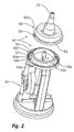
- the invention essential feature lies in the flow brake device 40, which in particular in Fig. 2 is clearly visible.
- This flow brake unit 40 has, in particular, a separate first flow brake component 60 and a second flow brake component 50, which is the front end of an inner component 34 of the discharge device represents.
- This second flow brake component 50 is aligned within the housing 11 in a predetermined position.
- the second flow brake component 50 has a peripheral annular surface 52 which points in the direction of the outlet opening 14 and is bounded on the inside and outside by circumferential webs 53a, 53b extending in the direction of the discharge opening 14.
- a groove 54 is inserted, which for better understanding in Fig. 1 is shown enlarged.
- This groove 54 extends in a circular section over a circular section of about 330 ° equidistant to the main extension axis 4 of the discharge.
- an inlet opening 16 a is provided, which is formed by the end of the channel 16.
- the groove 54 terminates at its opposite end 54b.
- the first flow brake component 60 which in Fig. 2 is shown for a better understanding in a raised position, is formed by an elastic member having the valve body 20 at its end. The elasticity of this component is responsible for the pressure-dependent opening of the exhaust valve 20.
- the first flow brake component 60 On the side 60a facing away from the valve body 20, the first flow brake component 60 has an annular covering surface 62 which points in the direction of the second flow brake component 50 and which is interrupted only in the region of an outlet zone 64 over an angular range of approximately 15 °.
- this first flow brake component 60 is mounted in the mounted state on the second flow brake component 50, so that the lower cover surface 62 of the first flow brake member 60 rests flush on the annular surface of 52 second flow brake component 50.
- the flow brake components 50, 60 are pressed together by a circumferential step 11a of the housing 11. This ensures that the rotational position of the first flow brake member 60th relative to the second flow brake component 50 relative to the main axis of attachment 4 is fixed non-positively.
- a flow brake channel section can be adjusted by varying this rotational position.
- This channel section is formed by the region of the groove 54 which is closed by the covering surface 62. Its length therefore depends on the relative position of the two flow brake components 50, 60 from each other. Depending on how long the sealed portion of the groove 54 is, through which the medium must flow on the way from the pumping device 30 to the pressure chamber 18, the throttling action of the flow brake device 40 changes.
- a specific rotational position of the first flow brake component 60 is selectively selected relative to the second flow brake component 50 in order to effect a length of the channel portion resulting therefrom and thus to achieve a specific discharge characteristic.
- a first extreme state is achieved when the components in the orientation of Fig. 1 be assembled, since in this case the inflow opening 16a is aligned with the exit zone 64.
- this state which is also in the Fig. 3a is shown schematically, therefore, the medium does not flow into the groove 54 to reach the pressure chamber 18. Instead, the medium along the in Fig. 1 dotted represented path 90 directly into the pressure chamber 18 to flow. This state is therefore the state with the lowest throttle effect.
- FIGS. 3a to 3d show different settings of the discharge in a highly schematic representation from above.
- the second flow brake component 50 is shown by dashed lines. Shown here are from this second flow brake component 50 only the edges of the annular surface 52, the inflow opening 16a and the groove 54.
- the first flow brake member 60 is shown by solid lines. Only the lower cover surface 62 and the exit zone 64 are shown by the first flow brake component 60.
- Fig. 3a the same condition as the Fig. 1 In this first extreme state, the inflow opening 16a and the exit zone 64 are aligned, so that the medium can flow past the flow brake device 40 directly without the flow brake device 40 developing a significant throttling effect.
- This path is in Fig. 3a illustrated by the black colored zone 90.
- FIG. 11 shows a state in which the exit zone 64 is spaced 90 ° from the inlet 16a, so that the medium must flow along the black colored area 91 through a channel section formed by the groove 54 and the cover 62 before it reaches the exit zone 64 the flow brake device 40 can leave in the direction of the pressure chamber 18.
- Fig. 4 schematically shows such a design. Also in this configuration, a first and a second flow brake components 160, 150 are provided, which are arranged in a manner not shown within a discharge device.
- the second flow brake component 150 is largely planar and has an elongated groove 154, which is supplied with medium by an inflow channel 116a coming from below.
- the first flow brake component 160 is provided, on the underside of a cover surface 162 is provided.
- This first flow brake component 160 has two retaining pins 168 by means of which it can be positively inserted in variable positions in retaining openings 158 of the second flow brake component 150.
- FIGS. 5a to 5c illustrate these different relative positions. While the throttling effect of the flow brake in the relative position of the flow brake components 150, 160 of the Fig. 5a is relatively low, it is in the relative position of Fig. 5b already significantly larger. The relative position of Fig. 5c has the maximum throttling effect.
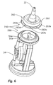
- Fig. 6 shows a further embodiment of a discharge device according to the invention. This agrees with most of the features with the design of the Fig. 1 to 3 match. Unless otherwise described below, the components agree with those of the discharge of the Fig. 1 to 3 match. Substantially identical components are identified by the same reference numerals.
- first flow brake member 260 which, like the flow brake member 60, is made of an elastic material.
- this first flow brake component 260 has a wider covering surface 262, in which five through-openings 263a-263e distributed over the circumference are provided.
- the rotational position of the first flow brake component 260 relative to the second flow brake component 250 is determined during assembly in such a way that a selected passage opening 263a-263e is arranged in alignment with the inflow opening 16a. Since the medium must flow through this aligned passage opening 263a-263e to reach the outlet opening 14, the characteristics of the selected passage opening 263a-263e greatly determine the characteristics of the flow brake 240 of the discharge device.
Landscapes
- Physics & Mathematics (AREA)
- Fluid Mechanics (AREA)
- Containers And Packaging Bodies Having A Special Means To Remove Contents (AREA)
- Braking Arrangements (AREA)
- Closures For Containers (AREA)
- Basic Packing Technique (AREA)
- Infusion, Injection, And Reservoir Apparatuses (AREA)
Description
- Die Erfindung betrifft eine Austragvorrichtung zum Austrag von flüssigen Medien mit einem Gehäuse, einer Auslassöffnung für das Medium, einem Medienspeicher zur Lagerung des Mediums und einer Fördereinrichtung zum Transportieren des Mediums aus dem Medienspeicher zur Auslassöffnung, wobei in einem Medienkanal zwischen der Fördereinrichtung und der Auslassöffnung eine Fließbremse vorgesehen ist.
- Gattungsgemäße Austragvorrichtungen sind aus dem Stand der Technik bekannt, siehe hierzu
US 4 712 738 . Sie dienen insbesondere dem Austrag von Medikamenten in flüssiger Form. Solche Austragvorrichtungen umfassen alle für den Austrag erforderlichen Komponenten und sind aufgrund der üblicherweise kleinen und kompakten Bauweise transportabel. - In Abhängigkeit des Anwendungszwecks sind bei bestimmten gattungsgemäßen Austragvorrichtungen besondere Formen des Austrags gewünscht. So ist beispielsweise bei einer Austragvorrichtung für Augentropfen gewünscht, dass das Medium in Tropfenform aus der Austragöffnung entweicht und dabei keinen Sprühstrahl bildet. Zur Erreichung dieser oder ähnlich angepasster Formen des Austrags ist es aus dem Stand der Technik bekannt, Fließbremsen vorzusehen. Hierbei handelt es sich um enge Durchgangsstellen oder Kanäle, durch die das Medium auf dem Weg zur Austragöffnung hindurch fließen muss, wobei in Abhängigkeit der Querschnittsfläche des Kanals quer zur Fließrichtung und der Länge des Kanals in Fließrichtung eine unterschiedlich starke Drosselwirkung erzielt wird.
- Allerdings ist es häufig erforderlich, für unterschiedliche Anwendungszwecke und/oder unterschiedliche Medien die Fließbremsen konstruktiv neu zu gestalten, um die spezifisch gewünschte Drosselwirkung zu erzielen. Dieser wiederkehrende konstruktive Aufwand wird als nachteilig empfunden.
- Aufgabe der Erfindung ist es daher, eine gattungsgemäße Austragvorrichtung dahingehend weiterzubilden, dass eine einfache Möglichkeit gegeben ist, mit möglichst geringem konstruktivem Aufwand die Wirkung der Fließbremse spezifisch für einen Anwendungsfall anzupassen.
- Erfindungsgemäß wird diese Aufgabe dadurch gelöst, dass die Fließbremse ein erstes Fließbremsenbauteil aufweist, welches relativ zum Gehäuse oder zu einem zweiten Fließbremsenbauteil während der Montage in mehreren voneinander abweichenden Relativstellungen anordenbar und festlegbar ist, wobei in Abhängigkeit der gewählten Relativstellungen voneinander abweichende Strömungswiderstände der Fließbremse bewirkt werden.
- Die Fließbremse kann bei einer solchen Ausgestaltung einer Austragvorrichtung an den konkreten Anwendungszweck angepasst werden. So kann bei höherviskosen Medien und/oder bei einer beabsichtigten geringen Drosselwirkung während der Montage ein geringer Strömungswiderstand der Fließbremse eingestellt werden, während bei einem niederviskosen Medium und/oder bei einer gewünschten starken Drosselwirkung ein hoher Strömungswiderstand eingestellt wird. Die Einstellung des Strömungswiderstandes und damit der erzielten Drosselwirkung wird während der Montage einmalig durch die Ausrichtung und/oder Anordnung des ersten Fließbremsenbauteils festgelegt. Diese Einstellung bleibt im montierten Zustand der Austragvorrichtung zumindest im Wesentlichen erhalten. Eine Veränderung der Einstellung durch den Benutzer ist nicht gewünscht. Daher ist das erste Fließbremsenbauteil vorzugsweise derart im Gehäuse angeordnet, dass eine Änderung der Relativlage ohne Zerlegen der Austragvorrichtung nicht möglich ist.
- Der abhängig von der Relativstellung des ersten Fließbremsenbauteils zum Gehäuse oder zum zweiten Fließbremsenbauteil variierende Strömungswiderstand wird dadurch erzielt, dass diese Relativstellung die Geometrie des Strömungspfades beeinflusst, entlang dessen das Medium zur Austragöffnung gefördert wird. Dies kann beispielsweise durch variierende Längen von engen Kanalabschnitten und/oder variierende Durchmesser von Durchlässen erreicht werden.
- Eine einfache Ausgestaltung sieht vor, dass das erste Fließbremsenbauteil einerseits und das zweite Fließbremsenbauteil oder das Gehäuse andererseits während der Montage translativ relativ zueinander ausrichtbar und festlegbar sind. Als besonders vorteilhaft wird jedoch eine Gestaltung angesehen, bei der das erste Fließbremsenbauteil einerseits und das zweite Fließbremsenbauteil oder das Gehäuse andererseits gegeneinander in verschiedene Drehstellungen ausrichtbar und in verschiedenen Drehstellungen festlegbar sind.
- Eine solche Ausgestaltung ist besonders platzsparend und konstruktiv einfach zu erzielen. Die Drehachse, um die das erste Fließbremsenbauteil relativ zum zweiten Fließbremsenbauteil oder dem Gehäuse verdrehbar ist, entspricht vorzugsweise der Haupterstreckungsachse der Austragvorrichtung und ist insbesondere vorzugsweise koaxial mit der Auslassöffnung ausgerichtet. Diese Nutzung der Haupterstreckungsachse als Drehachse für das erste Fließbremsenbauteil bietet den Vorteil, dass ein ohnehin schon vorgesehenes und im Wesentlichen rotationssymmetrisches Bauteil als erstes Fließbremsenbauteil genutzt werden kann. So ist beispielsweise insbesondere die Nutzung eines Ventilkörperbauteils, welches im montierten Zustand der Austragvorrichtung einseitig fest eingespannt ist, als erstes Fließbremsenbauteil zweckmäßig.
- Besonders von Vorteil ist es, wenn das zweite Fließbremsenbauteil gehäusefest vorgesehen ist und das erste Fließbremsenbauteil im Zuge der Montage gegenüber dem gehäusefesten zweiten Fließbremsenbauteil beweglich ist.
- Unter einer gehäusefesten Gestaltung eines der Fließbremsenbauteile wird dabei verstanden, dass die Ausrichtung dieses Fließbremsenbauteils relativ zum Gehäuse konstruktiv vorgegeben ist, beispielsweise durch eine einstückige oder formschlüssige Verbindung mit dem Gehäuse. Dies erleichtert den Montagevorgang, da eine angepasste Ausrichtung neben der ohnehin üblichen definierten Ausrichtung des Gehäuses nur hinsichtlich des ersten Fließbremsenbauteils erforderlich ist. Es ist daher besonders einfach, eine korrekte Ausrichtung beim maschinellen Herstellungsvorgang zu gewährleisten.
- Besonders von Vorteil ist es, wenn die Relativlage des ersten Fließbremsenbauteils zum Gehäuse oder zum zweiten Fließbremsenbauteil im montierten Zustand kraftschlüssig beibehalten wird. Eine solche kraftschlüssige Gestaltung ist hinsichtlich der Montagepräzision fehlertoleranter als eine kraftschlüssige Fixierung. Bei einer kraftschlüssigen Festlegung ist darüber hinaus eine stufenlose Anpassung der Relativlage des ersten Fließbremsenbauteils erzielbar, was je nach Ausgestaltung der Fließbremse eine stufenlose Einstellbarkeit des Strömungswiderstandes und damit der Drosselwirkung gestattet.
- Neben einer kraftschlüssigen Fixierung des ersten Fließbremsenbauteils relativ zum zweiten Fließbremsenbauteil oder relativ zum Gehäuse sind jedoch auch weitere Varianten denkbar, so zum Beispiel eine formschlüssige Sicherung, bei der eine Relativpositionierung der Fließbremsenbauteile zueinander nur in definierten Fixierlagen möglich ist.
- Bei einer Weiterbildung der Erfindung wird durch die beiden Fließbremsenbauteile ein Kanalabschnitt gebildet wird, wobei die Länge des Kanalabschnitts in Abhängigkeit der Relativstellung der beiden Fließbremsenbauteile variiert.
- Dieser durch die beiden Fließbremsenbauteile gebildete Fließbremsenkanalabschnitt hat vorzugsweise eine enge Querschnittsfläche. An der engsten Stelle beträgt die Querschnittsfläche vorzugsweise maximal 1 mm2, insbesondere vorzugsweise maximal 0,1 mm2. Die Querschnittsfläche kann über die Länge des Kanalabschnitts im Wesentlichen einheitlich sein. Es kann jedoch auch ein sich verjüngender oder aufweitender Kanal gebildet werden, so dass die Einstellung der Relativlage der Fließbremsenbauteile zueinander nicht nur die Kanallänge, sondern auch den engsten Kanalquerschnitt definiert.
- Bei dieser Weiterbildung liegen die Fließbremsenbauteile im montierten Zustand zumindest abschnittsweise unmittelbar aneinander an. Der Kanalabschnitt wird von den beiden Fließbremsenbauteilen gemeinsam begrenzt. Durch eine Vergrößerung oder Verkleinerung des Bereiches, in dem die Bauteile aneinander anliegen, kann ein längerer bzw. kürzerer Kanalabschnitt gebildet werden. Vorzugsweise lassen sich die Fließbremsenbauteile darüber hinaus auch in eine Relativstellung bringen, aus der eine Umgehungsmöglichkeit für das Medium resultiert. In dieser Relativstellung der Fließbremsenbauteile wird das Medium an den Fließbremsenbauteilen vorbeigeleitet und erfährt daher keine Drosselwirkung durch den Kanalabschnitt.
- Insbesondere bei der Weiterbildung mit zwei einen Kanalabschnitt definierenden Fließbremsenbauteilen wird es als vorteilhaft angesehen, wenn das erste Fließbremsenbauteil relativ zum zweiten Fließbremsenbauteil in verschiedene Drehstellungen ausrichtbar und in verschiedenen Drehstellungen festlegbar ist. Dies gestattet es, bei geringem Raumbedarf einen vergleichsweise langen Kanalabschnitt vorzusehen.
- Die beiden Fließbremsenbauteile sind bei dieser Gestaltung vorzugsweise zur gemeinsamen Bildung eines Kanalabschnitts ausgelegt, der um die gemeinsame Drehachse der beiden Teile verläuft. Vorzugsweise erstreckt sich der Kanalabschnitt äquidistant auf einem Kreisbogen um die Drehachse. Dies erlaubt es, je nach Anwendungszweck den Kanalabschnitt einen Winkel zwischen 0° und annähernd 360° überspannen zu lassen, so dass eine besonders flexible Anpassung möglich ist.
- Bei einer Weiterbildung der Erfindung weist eines der Fließbremsenbauteile eine Nut auf, wobei diese Nut durch das andere Fließbremsenbauteil zumindest abschnittsweise verschlossen ist. Bei einer solchen Ausgestaltung bilden die beiden Fließbremsenbauteile dadurch einen gemeinsamen Kanalabschnitt, dass in dem einen der Fließbremsenbauteile die genannte Nut, also ein Kanal mit einem an einer Seite offenen Querschnitt, vorgesehen ist. Das andere Fließbremsenbauteil ist dafür vorgesehen, diese offene Seite des Querschnitts über die Länge des zu bildenden Kanalabschnitts zu verschließen. Bei dieser Gestaltung wird der gebildete Kanalabschnitt durch den Teil der Nut des einen Fließbremsenbauteils gebildet, der durch das andere Fließbremsenbauteil verschlossen ist. Die Nut kann sich zwar jenseits dieses verschlossenen Bereichs weiter erstrecken, da das den verschlossenen Bereich durchströmende Medium jenseits des verschließenden zweiten Fließbremsenbauteils jedoch ungehindert aus der Nut austreten kann, bildet dieser Bereich keinen Teil des drosselnden Kanalabschnitts mehr und beeinflusst den Strömungswiderstand allenfalls in vernachlässigbarem Maße.
- Vorzugsweise sind beidseitig der Nut zueinander fluchtende Flächenabschnitte an einem Fließbremsenbauteil vorgesehen, so dass zum Verschließen des Fließbremsenbauteils mit der Nut lediglich eine plane Abschlussfläche am anderen Fließbremsenbauteile erforderlich ist.
- Als besonders vorteilhaft wird es angesehen, wenn die Nut in Richtung zur Auslassöffnung offen ist und dort durch das aus Richtung der Auslassöffnung aufgesetztes Fließbremsenbauteil verschlossen wird. Alternativ kann die Nut auch in radialer Richtung offen sein, wobei sie vorzugsweise nach innen offen ist, wo das innenseitig angeordnete Fließbremsenbauteil sie abschnittsweise verschließt.
- Der Zugang des Mediums in die Nut und der Austritt aus der Nut erfolgen vorzugsweise in gleicher Richtung. So ist es konstruktiv von Vorteil, wenn die Eintrittsöffnung in Richtung der Austragrichtung in die Nut mündet und das Medium am Ende der Nut in Richtung der Austragrichtung aus dieser austreten kann.
- Bei einer Weiterbildung der Erfindung ist eines der Fließbremsenbauteile zumindest abschnittsweise aus einem elastischen Material gefertigt, vorzugsweise aus einem Material mit einem E-Modul von weniger als 100 N/mm2. Die Gestaltung eines der Fließbremsenbauteile aus einem elastischen Material hat insbesondere zwei Vorteile: Zum einen wird dadurch eine sichere Abdichtung im Bereich des Kanalabschnitts erzielt.
- So kann beispielsweise das zweite Fließbremsenbauteil aus einem elastischen Material gefertigt sein, welches die Gegenfläche zum Verschließen der an einer Seite offenen Nut des ersten Fließbremsenbauteils bildet. Dabei wird bereits durch eine geringe Anpresskraft erreicht, dass diese elastische Gegenfläche sich zuverlässig an die Nutränder anlegt und somit ein ungewolltes Austreten des Mediums im Bereich der Fließbremse unterbunden wird. Der zweite Vorteil bei der Nutzung eines elastischen Materials liegt darin, dass auch die Fixierung der Fließbremsenbauteile zueinander besonders einfach erzielt werden kann. Zu diesem Zweck kann das elastische Fließbremsenbauteil gegen das andere Fließbremsenbauteil gepresst werden, so dass eine zuverlässige kraftschlüssige Verbindung erzielt wird.
- Bei einer Weiterbildung der Erfindung wird ein Durchlass mittels der beiden Fließbremsenbauteile gebildet, wobei die beiden Fließbremsenbauteile in Abhängigkeit ihrer Relativstellung zueinander einen minimalen Querschnitt des Durchlasses festlegen. Bei dieser Gestaltung wird demnach nicht primär die Länge eines Kanalabschnitts beeinflusst, sondern stattdessen der freie Querschnitt eines Durchlasses. Hinsichtlich der Gestaltung und Festlegung der Fließbremsenbauteile dieser Alternativgestaltung wird die Realisierung der Merkmale der oben genannten Weiterbildungen, so beispielsweise die kraftschlüssige oder formschlüssige Fixierung der Fließbremsenbauteile aneinander, ebenfalls als vorteilhaft angesehen.
- Bei einer anderen Weiterbildung der Erfindung weist die Fließbremse eine Mehrzahl von Durchlassöffnungen auf, wobei in Abhängigkeit der Relativstellung des ersten Fließbremsenbauteils zum Gehäuse oder zum zweiten Fließbremsenbauteil jeweils eine andere dieser Durchlassöffnungen von dem Medium beim Transport vom Medienspeicher zur Auslassöffnung durchquert werden muss.
- Bei einer solchen Gestaltung wird demnach nicht der gleiche Durchlass hinsichtlich seiner Eigenschaften durch eine Anpassung der Länge und/oder des Durchmessers angepasst. Stattdessen sind mehrere voneinander getrennte Durchlassöffnungen vorgesehen, wobei durch die Relativlage des ersten Fließbremsenbauteils zum zweiten Fließbremsenbauteil oder dem Gehäuse während der Montage festgelegt werden kann, welche der Durchlassöffnungen vom Medium auf dem Weg zur Austragöffnung durchquert werden muss. Die Durchlassöffnungen können sich voneinander durch ihren Querschnitt und/oder durch ihre Länge unterscheiden. Die Durchlassöffnungen brauchen nicht als von einer umlaufenden Wandung geschlossene Durchbrechungen ausgebildet sein, sondern können auch als entlang ihrer Erstreckungsrichtung nutartig einseitig offene und an dieser offenen Seite durch ein Gegenbauteil verschlossene Vertiefungen vorgesehen sein. Dies führt zu einfacheren Herstellungsprozessen.
- Bei einer ersten Alternative der Gestaltung mit einer Mehrzahl von Durchlassöffnungen ist die Mehrzahl von Durchlassöffnungen im zweiten Fließbremsenbauteil oder ortsfest zum Gehäuse angeordnet, wobei in Abhängigkeit der Relativstellung des ersten Fließbremsenbauteils zum Gehäuse oder zum zweiten Fließbremsenbauteil jeweils unterschiedliche Durchlassöffnungen verschlossen oder geöffnet sind. Bei dieser Ausgestaltung muss demnach während der Montage keine Lageanpassung der Durchlassöffnungen erfolgen. Die Festlegung des Strömungswiderstandes der Fließbremse erfolgt stattdessen dadurch, dass einige der Durchlasskanäle durch das erste Fließbremsenbauteil verschlossen werden, während mindestens einer der Durchlassöffnungen vom ersten Fließbremsenbauteil nicht verschlossen wird.
- Alternativ hierzu kann bei einer anderen Gestaltung mit einer Mehrzahl von Durchlassöffnungen vorgesehen sein, dass die Mehrzahl von Durchlassöffnungen im erstem Fließbremsenbauteil vorgesehen sind, wobei in Abhängigkeit der Relativstellung des ersten Fließbremsenbauteils zum Gehäuse oder zum zweiten Fließbremsenbauteil verschiedene der Durchlassöffnungen im Strömungspfad des Mediums zur Auslassöffnung angeordnet sind. Bei dieser Gestaltung werden demnach nicht die Durchlassöffnungen durch das erste Fließbremsenbauteil verschlossen. Stattdessen wird in Abhängigkeit der Relativstellung des ersten Fließbremsenbauteils jeweils ein anderer der im ersten Fließbremsenbauteil vorgesehenen Durchlassöffnungen so angeordnet, dass das Medium auf dem Weg zur Auslassöffnung die betreffende Durchlassöffnung durchqueren muss.
- Weitere Aspekte und Vorteile der Erfindung ergeben sich außer aus den Ansprüchen auch aus einer nachfolgenden Beschreibung zweier bevorzugter Ausführungsbeispiele der Erfindung, welche in den nachfolgenden Figuren dargestellt sind. Dabei zeigen:
- Fig. 1
- eine erste Ausführungsform einer erfindungsgemäßen Austragvorrichtung in einer geschnittenen Seitendarstellung,
- Fig. 2
- die Austragvorrichtung der
Fig. 1 mit abgenommenem Außengehäuse, - Fig. 3a bis 3d
- verschiedene Konfigurationen der Fließbremse der Austragvorrichtung der
Fig. 1 und2 , - Fig. 4
- eine alternative Form einer einstellbaren Fließbremse,
- Fig. 5
- verschiedene Konfigurationen der Fließbremse gemäß
Fig. 4 und - Fig. 6
- eine weitere Ausführungsform einer erfindungsgemäßen Austragvorrichtung mit abgenommenem Außengehäuse.
-
Fig. 1 zeigt eine erste Ausführungsform einer erfindungsgemäßen Austragvorrichtung. Diese Austragvorrichtung weist als Hauptkomponenten eine Förder- und Austragseinheit 10 sowie einen daran angekoppelten Medienspeicher 8 auf. - In der Förderungs- und Austragseinheit 10, die durch ein Außengehäuse 11 abgeschlossen ist, ist eine über einen Betätigungstaster 32 betätigbare Pumpvorrichtung 30 mit einer durch einen Balg gebildeten Pumpkammer vorgesehen, die über einen Einlasskanal 12 mit dem Medienspeicher verbunden ist. Diese Pumpvorrichtung 30 ist dafür vorgesehen, Medium aus dem Medienspeicher 20 anzusaugen und unter Druck zu einer Austrittsöffnung 14 zu fördern. Hierzu ist ausgehend von der Pumpvorrichtung 30 ein Verbindungskanal 16 vorgesehen, der über eine Fließbremseneinrichtung 40 mit einem Druckraum 18 verbunden ist. Der Druckraum 18 ist Teil eines Auslassventils 20, dessen Ventilkörper 22 bei einem ausreichend hohen Druck in der Druckkammer 18 in Richtung des Pfeils 2 verschoben wird, so dass die Auslassöffnung 14 freigegeben wird.
- Die erfindungswesentliche Besonderheit liegt in der Fließbremseneinrichtung 40, welche insbesondere in
Fig. 2 deutlich zu erkennen ist. Diese Fließbremseneinheit 40 weist insbesondere ein separates erstes Fließbremsenbauteil 60 sowie ein zweites Fließbremsenbauteil 50 auf, welches das Stirnende eines Innenbauteils 34 der Austragvorrichtung darstellt. Dieses zweite Fließbremsenbauteil 50 ist innerhalb des Gehäuses 11 in einer vorgegebenen Position ausgerichtet. - Das zweite Fließbremsenbauteil 50 weist eine in Richtung der Auslassöffnung 14 weisende umlaufende Ringfläche 52 auf, die innenseitig und außenseitig durch in Richtung der Austragöffnung 14 erstreckte umlaufende Stege 53a, 53b begrenzt wird. In diese Ringfläche 52 ist eine Nut 54 eingebracht, die zum besseren Verständnis in
Fig. 1 vergrößert dargestellt ist. Diese Nut 54 erstreckt sich kreisabschnittsförmig über einen Kreisabschnitt von ca. 330° äquidistant zur Haupterstreckungsachse 4 der Austragvorrichtung. An einem Nuteingang 54a ist eine Zuflussöffnung 16a vorgesehen, der durch das Ende des Kanals 16 gebildet wird. Etwa um die genannten 330° von diesem Eingang 54a beabstandet endet die Nut 54 an ihrem gegenüberliegenden Ende 54b. - Das erste Fließbremsenbauteil 60, das in
Fig. 2 zum besseren Verständnis in einer angehobenen Position dargestellt ist, wird durch ein elastisches Bauteil gebildet, welches an seinem Ende den Ventilkörper 20 aufweist. Die Elastizität dieses Bauteils ist für das druckabhängige Öffnen des Auslassventils 20 verantwortlich. An der dem Ventilkörper 20 abgewandten Seite 60a weist das erste Fließbremsenbauteil 60 eine ringförmige Abdeckfläche 62 auf, die in Richtung des zweiten Fließbremsenbauteils 50 weist und die lediglich im Bereich einer Austrittszone 64 über einen Winkelbereich von etwa 15° unterbrochen ist. - Wie aus der
Fig. 1 ersichtlich ist, ist dieses erste Fließbremsenbauteil 60 im montierten Zustand auf das zweite Fließbremsenbauteil 50 aufgesetzt, so dass die untere Abdeckfläche 62 des ersten Fließbremsenbauteils 60 bündig auf der Ringfläche des 52 zweiten Fließbremsenbauteils 50 aufliegt. Dabei werden die Fließbremsenbauteile 50, 60 durch eine umlaufende Stufe 11a des Gehäuses 11 aneinander gepresst. Hierdurch wird erreicht, dass die Drehstellung des ersten Fließbremsenbauteils 60 relativ zum zweiten Fließbremsenbauteil 50 bezogen auf die Hauptersteckungsachse 4 kraftschlüssig fixiert ist. - Während der Montage der Austragvorrichtung kann durch Variieren dieser Drehstellung die Länge eines Fließbremsenkanalabschnitts eingestellt werden. Dieser Kanalabschnitt wird durch den durch die Abdeckfläche 62 verschlossenen Bereich der Nut 54 gebildet. Seine Länge hängt daher von der Relativlage der beiden Fließbremsenbauteile 50, 60 zueinander ab. Abhängig davon, wie lang der verschlossene Abschnitt der Nut 54 ist, durch den hindurch das Medium auf dem Weg von der Pumpvorrichtung 30 bis zur Druckkammer 18 hindurchfließen muss, ändert sich die Drosselwirkung der Fließbremseneinrichtung 40.
- Bei der Montage wird demnach gezielt eine bestimmte Drehstellung des ersten Fließbremsenbauteils 60 relativ zum zweiten Fließbremsenbauteil 50 gewählt, um eine daraus resultierende Länge des Kanalabschnitts zu bewirken und so eine spezifische Austragcharakteristik zu erzielen.
- Ein erster Extremzustand ist dabei erreicht, wenn die Bauteile in der Ausrichtung der
Fig. 1 zusammengesetzt werden, da in diesem Fall die Zuflussöffnung 16a mit der Austrittszone 64 fluchtet. In diesem Zustand, der auch in derFig. 3a schematisch dargestellt ist, muss das Medium daher nicht in die Nut 54 einfließen, um zur Druckkammer 18 zu gelangen. Stattdessen kann das Mediums entlang des inFig. 1 gepunktet dargestellten Pfades 90 direkt in die Druckkammer 18 einströmen. Dieser Zustand ist demnach der Zustand mit der geringsten Drosselwirkung. - Die
Figuren 3a bis 3d zeigen verschiedene Einstellungen der Austragvorrichtung in einer stark schematisierten Darstellung von oben. Dabei ist das zweite Fließbremsenbauteil 50 durch gestrichelte Linien dargestellt. Dargestellt sind dabei von diesem zweiten Fließbremsenbauteil 50 lediglich die Ränder der Ringfläche 52, die Zuflussöffnung 16a sowie die Nut 54. Das erste Fließbremsenbauteil 60 ist mit durchgezogenen Linien dargestellt. Dabei sind vom ersten Fließbremsenbauteil 60 lediglich die untere Abdeckfläche 62 sowie die Austrittszone 64 dargestellt. - Wie bereits erwähnt, stellt die
Fig. 3a denselben Zustand wie dieFig. 1 dar. In diesem ersten Extremzustand fluchten die Zuflussöffnung 16a und die Austrittszone 64, so dass das Medium unmittelbar an der Fließbremseneinrichtung 40 vorbeifließen kann, ohne dass die Fließbremseneinrichtung 40 eine nennenswerte Drosselwirkung entfaltet. Dieser Weg ist inFig. 3a anhand der schwarz eingefärbten Zone 90 verdeutlicht. -
Fig. 3b zeigt einen Zustand, bei dem die Austrittszone 64 um 90° gegenüber dem Zufluss 16a beabstandet ist, so dass das Medium entlang des schwarz eingefärbten Bereichs 91 durch einen durch die Nut 54 und der Abdeckfläche 62 gebildeten Kanalabschnitt strömen muss, bevor es an der Austrittszone 64 die Fließbremseneinrichtung 40 in Richtung der Druckkammer 18 verlassen kann. - Eine weitere Erhöhung der Drosselwirkung ist bei der dargestellten Konfiguration der
Fig. 3c beabsichtigt. Bei dieser Ausgestaltung sind die Austrittszone 64 und die Einlassöffnung 16a um etwa 180° voneinander beabstandet, so dass der vergleichsweise lange Weg 92 vom Medium im Kanalabschnitt zurückgelegt werden muss. - Die höchste Fließbremsenwirkung lässt sich bei einer Ausrichtung gemäß der
Fig. 3d erzielen. Bei dieser Ausrichtung ist die Auslasszone 64 über dem Ende 54b der Nut 54 angeordnet, so dass das Medium über einen Winkelbereich von etwa 330° entlang des Pfades 93 durch die von der Abdeckfläche 62 verschlossene Nut 54 strömen muss, um erst anschließend durch die Auslasszone 64 hindurch in die Druckkammer 18 gelangen zu können. - Auch wenn die Gestaltung mit zwei Fließbremsenbauteilen 50, 60, die gegeneinander um eine Drehachse 4 verdrehbar sind, als in vielerlei Hinsicht vorteilhaft angesehen wird, ist es auch möglich, diese beiden Fließbremsenbauteile translativ gegeneinander beweglich auszugestalten.
Fig. 4 zeigt schematisch eine solche Gestaltung. Auch bei dieser Gestaltung sind ein erstes und ein zweites Fließbremsenbauteile 160, 150 vorgesehen, die in nicht näher dargestellter Art und Weise innerhalb einer Austragvorrichtung angeordnet sind. - Das zweite Fließbremsenbauteil 150 ist weitgehend plan ausgebildet und weist eine längserstreckte Nut 154 auf, die durch einen von unten kommenden Zuflusskanal 116a mit Medium versorgt wird. Korrespondierend zum zweiten Fließbremsenbauteil 150 ist das erste Fließbremsenbauteil 160 vorgesehen, an dessen Unterseite eine Abdeckfläche 162 vorgesehen ist. Dieses erste Fließbremsenbauteil 160 verfügt über zwei Haltestifte 168 mittels derer es formschlüssig in variablen Positionen in Halteöffnungen 158 des zweiten Fließbremsenbauteils 150 eingesetzt werden kann.
- Abhängig davon, welche Relativlage der beiden Fließbremsenbauteile 150, 160 dabei gewählt wird, muss das Medium auf dem Weg von der Zuflussöffnung 116a zum Austritt aus der Nut 154 unterschiedlich lange Abschnitte in der durch die Abdeckfläche 162 verschlossenen Nut 154 durchqueren. Die
Figuren 5a bis 5c verdeutlichen diese unterschiedlichen Relativlagen. Während die Drosselwirkung der Fließbremse bei der Relativlage der Fließbremsenbauteile 150, 160 derFig. 5a relativ gering ist, ist sie bei der Relativlage derFig. 5b bereits deutlich größer. Die Relativlage derFig. 5c weist die maximale Drosselwirkung auf. -
Fig. 6 zeigt eine weitere Ausgestaltung einer erfindungsgemäßen Austragvorrichtung. Diese stimmt hinsichtlich der meisten Merkmale mit der Ausgestaltung derFig. 1 bis 3 überein. Soweit nicht nachfolgend anders beschrieben, stimmen die Komponenten mit denen der Austragvorrichtung derFig. 1 bis 3 überein. Im Wesentlichen identische Komponenten sind mit den gleichen Bezugsziffern gekennzeichnet. - Aus der Darstellung der
Fig. 6 , die im Wesentlichen der Darstellung derFig. 2 entspricht, ist zu ersehen, dass bei dieser Ausgestaltung am zweiten Fließbremsenbauteil 250 keine Nut vorgesehen ist, sondern lediglich die Zuflussöffnung 16a. - Der wesentliche Unterschied zur Ausgestaltung der
Fig. 1 bis 3 liegt jedoch in dem ersten Fließbremsenbauteil 260, welches wie das Fließbremsenbauteil 60 aus einem elastischen Material besteht. Dieses erste Fließbremsenbauteil 260 weist jedoch eine breitere Abdeckfläche 262 auf, in der auf dem Umfang verteilt fünf Durchlassöffnungen 263a - 263e vorgesehen sind. - Um eine spezielle Drosselwirkung zu erzielen, wird während der Montage die Drehstellung des ersten Fließbremsenbauteils 260 gegenüber dem zweiten Fließbremsenbauteil 250 derart festgelegt, dass eine gewählte Durchlassöffnung 263a - 263e mit der Zuflussöffnung 16a fluchtend angeordnet ist. Da das Medium durch diese fluchtend angeordnete Durchlassöffnung 263a - 263e hindurch fließen muss, um zur Auslassöffnung 14 zu gelangen, bestimmen die Eigenschaften der gewählten Durchlassöffnung 263a - 263e in starkem Maße die Eigenschaften der Fließbremse 240 der Austragvorrichtung.
Claims (12)
- Austragvorrichtung zum Austrag von flüssigen Medien mit- einem Gehäuse (11),- einer Auslassöffnung (14) für das Medium,- einem Medienspeicher (8) zur Lagerung des Mediums und- einer Fördereinrichtung (30) zum Transportieren des Mediums aus dem Medienspeicher (8) zur Auslassöffnung (14),wobei in einem Medienkanal (16, 18) zwischen der Fördereinrichtung (30) und der Auslassöffnung (14) eine Fließbremse (40; 240) vorgesehen ist, und wobei
die Fließbremse (40; 240) ein erstes Fließbremsenbauteil (60; 160; 260) aufweist, welches relativ zum Gehäuse (11) oder zu einem zweiten Fließbremsenbauteil (50; 150; 250) während der Montage in mehreren voneinander abweichenden Relativstellungen anordenbar und festlegbar ist, wobei in Abhängigkeit der gewählten Relativstellungen voneinander abweichende Strömungswiderstände der Fließbremse bewirkt werden, dadurch gekennzeichnet, dass die Festlegung derart ist, dass eine Veränderung der Relativstellung nach der Montage für einen Benutzer ohne Zerlegen der Austragvorrichtung nicht möglich ist. - Austragvorrichtung nach Anspruch 1,
dadurch gekennzeichnet, dass
das erste Fließbremsenbauteil (60; 260) einerseits und das zweite Fließbremsenbauteil (50; 150) oder das Gehäuse (11) andererseits relativ zueinander in verschiedene Drehstellungen ausrichtbar und in verschiedenen Drehstellungen festlegbar sind. - Austragvorrichtung nach Anspruch 1 oder 2,
dadurch gekennzeichnet, dass
das zweite Fließbremsenbauteil (50; 150; 250) gehäusefest vorgesehen ist und das erste Fließbremsenbauteil (60; 160; 260) im Zuge der Montage gegenüber dem gehäusefesten zweiten Fließbremsenbauteil (50; 150; 250) beweglich ist. - Austragvorrichtung nach einem der vorstehenden Ansprüche,
dadurch gekennzeichnet, dass
die Relativlage des ersten Fließbremsenbauteils (60; 260) zum Gehäuse (11) oder zum zweiten Fließbremsenbauteil (50; 250) im montierten Zustand kraftschlüssig beibehalten wird. - Austragvorrichtung nach einem der vorstehenden Ansprüche,
dadurch gekennzeichnet, dass
durch die beiden Fließbremsenbauteile (50, 60; 150, 160) ein Kanalabschnitt (54, 62; 154, 162) gebildet wird, wobei die Länge des Kanalabschnitts (54, 62; 154, 162) in Abhängigkeit der Relativstellung der beiden Fließbremsenbauteile (50, 60; 150, 160) variiert. - Austragvorrichtung nach einem der vorstehenden Ansprüche,
dadurch gekennzeichnet, dass
eines der Fließbremsenbauteile (50; 150) eine Nut (54; 154) aufweist, wobei durch das andere Fließbremsenbauteil (60; 160) diese Nut (54; 154) zumindest abschnittsweise verschlossen ist. - Austragvorrichtung nach Anspruch 6,
dadurch gekennzeichnet, dass
die Nut (54; 154) bezogen auf die durch eine Austragrichtung definierte Haupterstreckungsrichtung (4)- in axialer Richtung, vorzugsweise in Richtung der Austragvorrichtung (14), offen ist oder- in radialer Richtung, vorzugsweise nach innen, offen ist. - Austragvorrichtung nach einem der vorstehenden Ansprüche,
dadurch gekennzeichnet, dass
eines der Fließbremsenbauteile (60; 260) zumindest abschnittsweise aus einem elastischen Material besteht, vorzugsweise aus einem Material mit einem E-Modul von weniger als 100 N/mm2. - Austragvorrichtung nach einem der Ansprüche 1 bis 4,
dadurch gekennzeichnet, dass
ein Durchlass mittels der beiden Fließbremsenbauteile gebildet wird, wobei die beiden Fließbremsenbauteile in Abhängigkeit ihrer Relativstellung zueinander einen minimalen Querschnitt des Durchlasses festlegen. - Austragvorrichtung nach einem der Ansprüche 1 bis 4,
dadurch gekennzeichnet, dass
die Fließbremse (240) eine Mehrzahl von Durchlassöffnungen (263a - 263e) aufweist, wobei in Abhängigkeit der Relativstellung des ersten Fließbremsenbauteils (260) zum Gehäuse (11) oder zum zweiten Fließbremsenbauteil (250) jeweils eine andere dieser Durchlassöffnungen (263a - 263e) von dem Medium beim Transport vom Medienspeicher (8) zur Auslassöffnung (14) durchquert werden muss. - Austragvorrichtung nach Anspruch 10,
dadurch gekennzeichnet, dass
die Mehrzahl von Durchlassöffnungen im zweiten Fließbremsenbauteil oder ortsfest zum Gehäuse angeordnet ist, wobei in Abhängigkeit der Relativstellung des ersten Fließbremsenbauteils zum Gehäuse oder zum zweiten Fließbremsenbauteil jeweils unterschiedliche Durchlassöffnungen verschlossen oder geöffnet sind. - Austragvorrichtung nach Anspruch 10,
dadurch gekennzeichnet, dass
die Mehrzahl von Durchlassöffnungen (263a - 263e) im ersten Fließbremsenbauteil (260) vorgesehen ist, wobei in Abhängigkeit der Relativstellung des ersten Fließbremsenbauteils (260) zum Gehäuse (11) oder zum zweiten Fließbremsenbauteil (250) verschiedene der Durchlassöffnungen (263a - 263e) im Strömungspfad des Mediums zur Auslassöffnung (14) angeordnet sind.
Applications Claiming Priority (1)
| Application Number | Priority Date | Filing Date | Title |
|---|---|---|---|
| DE102009006431A DE102009006431B4 (de) | 2009-01-23 | 2009-01-23 | Austragvorrichtung |
Publications (2)
| Publication Number | Publication Date |
|---|---|
| EP2210670A1 EP2210670A1 (de) | 2010-07-28 |
| EP2210670B1 true EP2210670B1 (de) | 2013-08-28 |
Family
ID=41666615
Family Applications (1)
| Application Number | Title | Priority Date | Filing Date |
|---|---|---|---|
| EP09015414.7A Active EP2210670B1 (de) | 2009-01-23 | 2009-12-14 | Austragvorrichtung |
Country Status (4)
| Country | Link |
|---|---|
| US (1) | US8561859B2 (de) |
| EP (1) | EP2210670B1 (de) |
| JP (1) | JP5412302B2 (de) |
| DE (1) | DE102009006431B4 (de) |
Families Citing this family (8)
| Publication number | Priority date | Publication date | Assignee | Title |
|---|---|---|---|---|
| DE102010063587B4 (de) | 2010-12-20 | 2018-03-15 | Aptar Radolfzell Gmbh | Austragvorrichtung für eine Flüssigkeit |
| DE102012210143A1 (de) | 2012-06-15 | 2013-12-19 | Aptar Radolfzell Gmbh | Prüfgerät für einen Flüssigkeitsspender |
| WO2014018847A1 (en) | 2012-07-26 | 2014-01-30 | Allergan, Inc. | Dual cap system for container-closures to maintain tip sterility during shelf storage |
| FR3006967A1 (fr) * | 2013-06-14 | 2014-12-19 | Valeo Systemes Dessuyage | Recipient de fluide lave-glace, organe destine a etre relie a ce recipient et dispositif comprenant les dits recipient et organe |
| DE102016212892C5 (de) | 2016-07-14 | 2020-01-30 | F. Holzer Gmbh | Pumpkopf sowie Dosiervorrichtung |
| US10829276B2 (en) | 2017-02-01 | 2020-11-10 | Silgan Dispensing Systems Hemer Gmbh | Dispenser for a liquid |
| FR3072311A1 (fr) * | 2017-10-12 | 2019-04-19 | Promens Sa | Dispositif de distribution de produits liquides a pateux avec dispositif de fermeture formant un module |
| EP3730220B1 (de) * | 2019-04-26 | 2022-07-06 | Aptar Radolfzell GmbH | Spender zum austrag pharmazeutischer flüssigkeiten |
Family Cites Families (16)
| Publication number | Priority date | Publication date | Assignee | Title |
|---|---|---|---|---|
| US3998427A (en) * | 1975-12-11 | 1976-12-21 | Clarence Bentley | Self-cleaning drip irrigation valve |
| US4598865A (en) * | 1983-10-24 | 1986-07-08 | Siseido Co., Ltd. | Sprayer cap structure |
| US4712738A (en) * | 1984-03-19 | 1987-12-15 | Nomix Manufacturing Co. Limited | Spraying equipment |
| JPS6284439U (de) * | 1985-11-18 | 1987-05-29 | ||
| JPH052195Y2 (de) * | 1987-12-18 | 1993-01-20 | ||
| JPH01122857U (de) * | 1988-01-29 | 1989-08-21 | ||
| DE69017121D1 (de) * | 1989-08-21 | 1995-03-30 | Nomix Chipman Ltd | Kalibrierung einer Flüssigkeitsverteileinrichtung. |
| JPH0354653U (de) * | 1989-10-02 | 1991-05-27 | ||
| EP0687240A1 (de) * | 1993-03-09 | 1995-12-20 | LECOFFRE, Yves | Vorrichtung zum spenden sehr kleiner abgaben einer in einem behälter enthaltenden flüssigkeit |
| KR100311592B1 (ko) * | 1994-11-17 | 2002-11-27 | 가부시키가이샤 요시노 고교쇼 | 거품분출펌프부착용기 |
| US5704550A (en) * | 1995-12-08 | 1998-01-06 | Contico International, Inc. | Liquid dispenser with flow control |
| JP2001061545A (ja) * | 1999-08-30 | 2001-03-13 | Suzuno Kasei Kk | 液状化粧料容器 |
| JP2004345738A (ja) * | 2003-04-28 | 2004-12-09 | Shiseido Co Ltd | 定量吐出容器 |
| DE102004050679A1 (de) * | 2004-10-13 | 2006-04-20 | Ing. Erich Pfeiffer Gmbh | Dosiervorrichtung |
| DE102005056488A1 (de) * | 2005-11-21 | 2007-05-24 | Ing. Erich Pfeiffer Gmbh | Spender und Dosierbaugruppe für die Mediumdosierung |
| JP5528336B2 (ja) * | 2007-07-06 | 2014-06-25 | マンタ デバイシス,エルエルシー | デリバリー装置及び関連方法 |
-
2009
- 2009-01-23 DE DE102009006431A patent/DE102009006431B4/de not_active Withdrawn - After Issue
- 2009-12-14 EP EP09015414.7A patent/EP2210670B1/de active Active
-
2010
- 2010-01-14 US US12/657,127 patent/US8561859B2/en active Active
- 2010-01-18 JP JP2010008106A patent/JP5412302B2/ja active Active
Also Published As
| Publication number | Publication date |
|---|---|
| DE102009006431B4 (de) | 2010-12-30 |
| JP2010168118A (ja) | 2010-08-05 |
| US20100187261A1 (en) | 2010-07-29 |
| DE102009006431A1 (de) | 2010-07-29 |
| JP5412302B2 (ja) | 2014-02-12 |
| EP2210670A1 (de) | 2010-07-28 |
| US8561859B2 (en) | 2013-10-22 |
Similar Documents
| Publication | Publication Date | Title |
|---|---|---|
| EP2210670B1 (de) | Austragvorrichtung | |
| EP2451586B1 (de) | Farbspritzpistole | |
| EP1606539B1 (de) | Teileinheit eines drosselklappenstutzens | |
| DE2430410A1 (de) | Ventil, insbesondere kugelventil | |
| EP0855223A2 (de) | Rotordüsenkopf | |
| EP3290757B1 (de) | Drehschieber mit kompakter dichtungseinheit | |
| DE102016116550B4 (de) | Drehschieberventil mit kompaktem Dichtelement | |
| EP3665399A1 (de) | Fluiddämpfer für gegeneinander verstellbare teile mit einem in einem zylinder verstellbar geführten kolben | |
| WO2000066910A1 (de) | Gummilager mit radialer wegbegrenzung und dämpfungsmittelkanal | |
| DE69727678T2 (de) | Activierungsstift | |
| WO2008043754A1 (de) | Drosselklappenstutzen | |
| EP3618891A1 (de) | Tropfkammeranordnung für ein medizinisches infusionssystem | |
| DE19503445A1 (de) | Hydraulisch dämpfendes Lager | |
| DE3215696C2 (de) | Drosselrückschlagventil | |
| WO2019238711A1 (de) | Zentrifuge | |
| DE10359609A1 (de) | Drosselklappenstutzen | |
| EP3092430B1 (de) | Ventileinrichtung zum steuern eines fluids, insbesondere eines abrasiven dickstoffs | |
| DE202011003941U1 (de) | Farbspritzpistole | |
| EP1811212B1 (de) | Teileinheit eines Drosselklappenstutzens | |
| DE4201959A1 (de) | Schraubendruckfederanordnung | |
| DE1960683C3 (de) | Fliehkraftdruckregler, insbesondere für eine Steueranlage von Kraftfahrzeug Wechselgetrieben | |
| EP2581614A2 (de) | Kugelschwenkmodul | |
| DE202016102769U1 (de) | Wasserflussregelanordnung einer Gartenspritzpistole und Sperrventil-Anschluss dafür | |
| DE4132709C2 (de) | Verstelldrosselventil | |
| DE102014217737A1 (de) | Klappenelement und eine Anordnung von Klappenelementen |
Legal Events
| Date | Code | Title | Description |
|---|---|---|---|
| PUAI | Public reference made under article 153(3) epc to a published international application that has entered the european phase |
Free format text: ORIGINAL CODE: 0009012 |
|
| AK | Designated contracting states |
Kind code of ref document: A1 Designated state(s): AT BE BG CH CY CZ DE DK EE ES FI FR GB GR HR HU IE IS IT LI LT LU LV MC MK MT NL NO PL PT RO SE SI SK SM TR |
|
| AX | Request for extension of the european patent |
Extension state: AL BA RS |
|
| 17P | Request for examination filed |
Effective date: 20100812 |
|
| RAP1 | Party data changed (applicant data changed or rights of an application transferred) |
Owner name: APTAR RADOLFZELL GMBH |
|
| REG | Reference to a national code |
Ref country code: DE Ref legal event code: R079 Ref document number: 502009007863 Country of ref document: DE Free format text: PREVIOUS MAIN CLASS: B05B0001300000 Ipc: B05B0001340000 |
|
| GRAP | Despatch of communication of intention to grant a patent |
Free format text: ORIGINAL CODE: EPIDOSNIGR1 |
|
| RIC1 | Information provided on ipc code assigned before grant |
Ipc: B05B 11/00 20060101ALI20130221BHEP Ipc: B05B 1/34 20060101AFI20130221BHEP |
|
| GRAS | Grant fee paid |
Free format text: ORIGINAL CODE: EPIDOSNIGR3 |
|
| GRAA | (expected) grant |
Free format text: ORIGINAL CODE: 0009210 |
|
| AK | Designated contracting states |
Kind code of ref document: B1 Designated state(s): AT BE BG CH CY CZ DE DK EE ES FI FR GB GR HR HU IE IS IT LI LT LU LV MC MK MT NL NO PL PT RO SE SI SK SM TR |
|
| REG | Reference to a national code |
Ref country code: GB Ref legal event code: FG4D Free format text: NOT ENGLISH |
|
| REG | Reference to a national code |
Ref country code: CH Ref legal event code: EP |
|
| REG | Reference to a national code |
Ref country code: AT Ref legal event code: REF Ref document number: 628986 Country of ref document: AT Kind code of ref document: T Effective date: 20130915 |
|
| REG | Reference to a national code |
Ref country code: IE Ref legal event code: FG4D Free format text: LANGUAGE OF EP DOCUMENT: GERMAN |
|
| REG | Reference to a national code |
Ref country code: DE Ref legal event code: R096 Ref document number: 502009007863 Country of ref document: DE Effective date: 20131024 |
|
| REG | Reference to a national code |
Ref country code: CH Ref legal event code: NV Representative=s name: WAGNER PATENT AG, CH |
|
| REG | Reference to a national code |
Ref country code: LT Ref legal event code: MG4D |
|
| REG | Reference to a national code |
Ref country code: NL Ref legal event code: VDEP Effective date: 20130828 |
|
| PG25 | Lapsed in a contracting state [announced via postgrant information from national office to epo] |
Ref country code: SE Free format text: LAPSE BECAUSE OF FAILURE TO SUBMIT A TRANSLATION OF THE DESCRIPTION OR TO PAY THE FEE WITHIN THE PRESCRIBED TIME-LIMIT Effective date: 20130828 Ref country code: CY Free format text: LAPSE BECAUSE OF FAILURE TO SUBMIT A TRANSLATION OF THE DESCRIPTION OR TO PAY THE FEE WITHIN THE PRESCRIBED TIME-LIMIT Effective date: 20130904 Ref country code: NO Free format text: LAPSE BECAUSE OF FAILURE TO SUBMIT A TRANSLATION OF THE DESCRIPTION OR TO PAY THE FEE WITHIN THE PRESCRIBED TIME-LIMIT Effective date: 20131128 Ref country code: PT Free format text: LAPSE BECAUSE OF FAILURE TO SUBMIT A TRANSLATION OF THE DESCRIPTION OR TO PAY THE FEE WITHIN THE PRESCRIBED TIME-LIMIT Effective date: 20131230 Ref country code: IS Free format text: LAPSE BECAUSE OF FAILURE TO SUBMIT A TRANSLATION OF THE DESCRIPTION OR TO PAY THE FEE WITHIN THE PRESCRIBED TIME-LIMIT Effective date: 20131228 Ref country code: LT Free format text: LAPSE BECAUSE OF FAILURE TO SUBMIT A TRANSLATION OF THE DESCRIPTION OR TO PAY THE FEE WITHIN THE PRESCRIBED TIME-LIMIT Effective date: 20130828 Ref country code: HR Free format text: LAPSE BECAUSE OF FAILURE TO SUBMIT A TRANSLATION OF THE DESCRIPTION OR TO PAY THE FEE WITHIN THE PRESCRIBED TIME-LIMIT Effective date: 20130828 |
|
| REG | Reference to a national code |
Ref country code: NL Ref legal event code: VDEP Effective date: 20130828 |
|
| PG25 | Lapsed in a contracting state [announced via postgrant information from national office to epo] |
Ref country code: SI Free format text: LAPSE BECAUSE OF FAILURE TO SUBMIT A TRANSLATION OF THE DESCRIPTION OR TO PAY THE FEE WITHIN THE PRESCRIBED TIME-LIMIT Effective date: 20130828 Ref country code: GR Free format text: LAPSE BECAUSE OF FAILURE TO SUBMIT A TRANSLATION OF THE DESCRIPTION OR TO PAY THE FEE WITHIN THE PRESCRIBED TIME-LIMIT Effective date: 20131129 Ref country code: LV Free format text: LAPSE BECAUSE OF FAILURE TO SUBMIT A TRANSLATION OF THE DESCRIPTION OR TO PAY THE FEE WITHIN THE PRESCRIBED TIME-LIMIT Effective date: 20130828 Ref country code: PL Free format text: LAPSE BECAUSE OF FAILURE TO SUBMIT A TRANSLATION OF THE DESCRIPTION OR TO PAY THE FEE WITHIN THE PRESCRIBED TIME-LIMIT Effective date: 20130828 Ref country code: FI Free format text: LAPSE BECAUSE OF FAILURE TO SUBMIT A TRANSLATION OF THE DESCRIPTION OR TO PAY THE FEE WITHIN THE PRESCRIBED TIME-LIMIT Effective date: 20130828 Ref country code: ES Free format text: LAPSE BECAUSE OF FAILURE TO SUBMIT A TRANSLATION OF THE DESCRIPTION OR TO PAY THE FEE WITHIN THE PRESCRIBED TIME-LIMIT Effective date: 20130828 |
|
| REG | Reference to a national code |
Ref country code: CH Ref legal event code: PCAR Free format text: NEW ADDRESS: BAECHERSTRASSE 9, 8832 WOLLERAU (CH) |
|
| PG25 | Lapsed in a contracting state [announced via postgrant information from national office to epo] |
Ref country code: CY Free format text: LAPSE BECAUSE OF FAILURE TO SUBMIT A TRANSLATION OF THE DESCRIPTION OR TO PAY THE FEE WITHIN THE PRESCRIBED TIME-LIMIT Effective date: 20130828 |
|
| PG25 | Lapsed in a contracting state [announced via postgrant information from national office to epo] |
Ref country code: CZ Free format text: LAPSE BECAUSE OF FAILURE TO SUBMIT A TRANSLATION OF THE DESCRIPTION OR TO PAY THE FEE WITHIN THE PRESCRIBED TIME-LIMIT Effective date: 20130828 Ref country code: SK Free format text: LAPSE BECAUSE OF FAILURE TO SUBMIT A TRANSLATION OF THE DESCRIPTION OR TO PAY THE FEE WITHIN THE PRESCRIBED TIME-LIMIT Effective date: 20130828 Ref country code: DK Free format text: LAPSE BECAUSE OF FAILURE TO SUBMIT A TRANSLATION OF THE DESCRIPTION OR TO PAY THE FEE WITHIN THE PRESCRIBED TIME-LIMIT Effective date: 20130828 Ref country code: EE Free format text: LAPSE BECAUSE OF FAILURE TO SUBMIT A TRANSLATION OF THE DESCRIPTION OR TO PAY THE FEE WITHIN THE PRESCRIBED TIME-LIMIT Effective date: 20130828 Ref country code: RO Free format text: LAPSE BECAUSE OF FAILURE TO SUBMIT A TRANSLATION OF THE DESCRIPTION OR TO PAY THE FEE WITHIN THE PRESCRIBED TIME-LIMIT Effective date: 20130828 Ref country code: NL Free format text: LAPSE BECAUSE OF FAILURE TO SUBMIT A TRANSLATION OF THE DESCRIPTION OR TO PAY THE FEE WITHIN THE PRESCRIBED TIME-LIMIT Effective date: 20130828 |
|
| REG | Reference to a national code |
Ref country code: DE Ref legal event code: R097 Ref document number: 502009007863 Country of ref document: DE |
|
| BERE | Be: lapsed |
Owner name: APTAR RADOLFZELL G.M.B.H. Effective date: 20131231 |
|
| PLBE | No opposition filed within time limit |
Free format text: ORIGINAL CODE: 0009261 |
|
| STAA | Information on the status of an ep patent application or granted ep patent |
Free format text: STATUS: NO OPPOSITION FILED WITHIN TIME LIMIT |
|
| 26N | No opposition filed |
Effective date: 20140530 |
|
| PG25 | Lapsed in a contracting state [announced via postgrant information from national office to epo] |
Ref country code: MC Free format text: LAPSE BECAUSE OF FAILURE TO SUBMIT A TRANSLATION OF THE DESCRIPTION OR TO PAY THE FEE WITHIN THE PRESCRIBED TIME-LIMIT Effective date: 20130828 Ref country code: LU Free format text: LAPSE BECAUSE OF FAILURE TO SUBMIT A TRANSLATION OF THE DESCRIPTION OR TO PAY THE FEE WITHIN THE PRESCRIBED TIME-LIMIT Effective date: 20131214 |
|
| REG | Reference to a national code |
Ref country code: DE Ref legal event code: R097 Ref document number: 502009007863 Country of ref document: DE Effective date: 20140530 |
|
| REG | Reference to a national code |
Ref country code: IE Ref legal event code: MM4A |
|
| PG25 | Lapsed in a contracting state [announced via postgrant information from national office to epo] |
Ref country code: IE Free format text: LAPSE BECAUSE OF NON-PAYMENT OF DUE FEES Effective date: 20131214 Ref country code: BE Free format text: LAPSE BECAUSE OF NON-PAYMENT OF DUE FEES Effective date: 20131231 |
|
| PG25 | Lapsed in a contracting state [announced via postgrant information from national office to epo] |
Ref country code: SM Free format text: LAPSE BECAUSE OF FAILURE TO SUBMIT A TRANSLATION OF THE DESCRIPTION OR TO PAY THE FEE WITHIN THE PRESCRIBED TIME-LIMIT Effective date: 20130828 |
|
| PG25 | Lapsed in a contracting state [announced via postgrant information from national office to epo] |
Ref country code: TR Free format text: LAPSE BECAUSE OF FAILURE TO SUBMIT A TRANSLATION OF THE DESCRIPTION OR TO PAY THE FEE WITHIN THE PRESCRIBED TIME-LIMIT Effective date: 20130828 |
|
| PG25 | Lapsed in a contracting state [announced via postgrant information from national office to epo] |
Ref country code: BG Free format text: LAPSE BECAUSE OF FAILURE TO SUBMIT A TRANSLATION OF THE DESCRIPTION OR TO PAY THE FEE WITHIN THE PRESCRIBED TIME-LIMIT Effective date: 20130828 Ref country code: MK Free format text: LAPSE BECAUSE OF FAILURE TO SUBMIT A TRANSLATION OF THE DESCRIPTION OR TO PAY THE FEE WITHIN THE PRESCRIBED TIME-LIMIT Effective date: 20130828 Ref country code: HU Free format text: LAPSE BECAUSE OF FAILURE TO SUBMIT A TRANSLATION OF THE DESCRIPTION OR TO PAY THE FEE WITHIN THE PRESCRIBED TIME-LIMIT; INVALID AB INITIO Effective date: 20091214 |
|
| PG25 | Lapsed in a contracting state [announced via postgrant information from national office to epo] |
Ref country code: MT Free format text: LAPSE BECAUSE OF FAILURE TO SUBMIT A TRANSLATION OF THE DESCRIPTION OR TO PAY THE FEE WITHIN THE PRESCRIBED TIME-LIMIT Effective date: 20130828 |
|
| REG | Reference to a national code |
Ref country code: FR Ref legal event code: PLFP Year of fee payment: 7 |
|
| REG | Reference to a national code |
Ref country code: DE Ref legal event code: R082 Ref document number: 502009007863 Country of ref document: DE Representative=s name: WITTE, WELLER & PARTNER PATENTANWAELTE MBB, DE Ref country code: DE Ref legal event code: R082 Ref document number: 502009007863 Country of ref document: DE Representative=s name: PATENTANWALTSKANZLEI CARTAGENA PARTNERSCHAFTSG, DE |
|
| REG | Reference to a national code |
Ref country code: AT Ref legal event code: MM01 Ref document number: 628986 Country of ref document: AT Kind code of ref document: T Effective date: 20141214 |
|
| PG25 | Lapsed in a contracting state [announced via postgrant information from national office to epo] |
Ref country code: AT Free format text: LAPSE BECAUSE OF NON-PAYMENT OF DUE FEES Effective date: 20141214 |
|
| REG | Reference to a national code |
Ref country code: FR Ref legal event code: PLFP Year of fee payment: 8 |
|
| REG | Reference to a national code |
Ref country code: FR Ref legal event code: PLFP Year of fee payment: 9 |
|
| REG | Reference to a national code |
Ref country code: DE Ref legal event code: R082 Ref document number: 502009007863 Country of ref document: DE Representative=s name: WITTE, WELLER & PARTNER PATENTANWAELTE MBB, DE |
|
| PGFP | Annual fee paid to national office [announced via postgrant information from national office to epo] |
Ref country code: IT Payment date: 20221230 Year of fee payment: 14 |
|
| P01 | Opt-out of the competence of the unified patent court (upc) registered |
Effective date: 20230502 |
|
| PGFP | Annual fee paid to national office [announced via postgrant information from national office to epo] |
Ref country code: GB Payment date: 20231220 Year of fee payment: 15 |
|
| PGFP | Annual fee paid to national office [announced via postgrant information from national office to epo] |
Ref country code: FR Payment date: 20231220 Year of fee payment: 15 Ref country code: DE Payment date: 20231004 Year of fee payment: 15 |
|
| PGFP | Annual fee paid to national office [announced via postgrant information from national office to epo] |
Ref country code: CH Payment date: 20240110 Year of fee payment: 15 |