EP2210262B1 - System and method for protecting a coil structure in a controlled switch - Google Patents
System and method for protecting a coil structure in a controlled switch Download PDFInfo
- Publication number
- EP2210262B1 EP2210262B1 EP07864564.5A EP07864564A EP2210262B1 EP 2210262 B1 EP2210262 B1 EP 2210262B1 EP 07864564 A EP07864564 A EP 07864564A EP 2210262 B1 EP2210262 B1 EP 2210262B1
- Authority
- EP
- European Patent Office
- Prior art keywords
- switch
- current
- load
- coil
- limiting device
- Prior art date
- Legal status (The legal status is an assumption and is not a legal conclusion. Google has not performed a legal analysis and makes no representation as to the accuracy of the status listed.)
- Not-in-force
Links
- 238000000034 method Methods 0.000 title claims description 26
- 238000010586 diagram Methods 0.000 description 10
- 230000006378 damage Effects 0.000 description 4
- 238000004378 air conditioning Methods 0.000 description 1
- 230000003247 decreasing effect Effects 0.000 description 1
- 229920000642 polymer Polymers 0.000 description 1
Images


Classifications
-
- H—ELECTRICITY
- H01—ELECTRIC ELEMENTS
- H01H—ELECTRIC SWITCHES; RELAYS; SELECTORS; EMERGENCY PROTECTIVE DEVICES
- H01H47/00—Circuit arrangements not adapted to a particular application of the relay and designed to obtain desired operating characteristics or to provide energising current
- H01H47/02—Circuit arrangements not adapted to a particular application of the relay and designed to obtain desired operating characteristics or to provide energising current for modifying the operation of the relay
- H01H47/04—Circuit arrangements not adapted to a particular application of the relay and designed to obtain desired operating characteristics or to provide energising current for modifying the operation of the relay for holding armature in attracted position, e.g. when initial energising circuit is interrupted; for maintaining armature in attracted position, e.g. with reduced energising current
- H01H47/06—Circuit arrangements not adapted to a particular application of the relay and designed to obtain desired operating characteristics or to provide energising current for modifying the operation of the relay for holding armature in attracted position, e.g. when initial energising circuit is interrupted; for maintaining armature in attracted position, e.g. with reduced energising current by changing number of serially-connected turns or windings
-
- H—ELECTRICITY
- H01—ELECTRIC ELEMENTS
- H01H—ELECTRIC SWITCHES; RELAYS; SELECTORS; EMERGENCY PROTECTIVE DEVICES
- H01H47/00—Circuit arrangements not adapted to a particular application of the relay and designed to obtain desired operating characteristics or to provide energising current
- H01H47/002—Monitoring or fail-safe circuits
-
- H—ELECTRICITY
- H01—ELECTRIC ELEMENTS
- H01H—ELECTRIC SWITCHES; RELAYS; SELECTORS; EMERGENCY PROTECTIVE DEVICES
- H01H47/00—Circuit arrangements not adapted to a particular application of the relay and designed to obtain desired operating characteristics or to provide energising current
- H01H47/02—Circuit arrangements not adapted to a particular application of the relay and designed to obtain desired operating characteristics or to provide energising current for modifying the operation of the relay
- H01H47/04—Circuit arrangements not adapted to a particular application of the relay and designed to obtain desired operating characteristics or to provide energising current for modifying the operation of the relay for holding armature in attracted position, e.g. when initial energising circuit is interrupted; for maintaining armature in attracted position, e.g. with reduced energising current
- H01H47/10—Circuit arrangements not adapted to a particular application of the relay and designed to obtain desired operating characteristics or to provide energising current for modifying the operation of the relay for holding armature in attracted position, e.g. when initial energising circuit is interrupted; for maintaining armature in attracted position, e.g. with reduced energising current by switching-in or -out impedance external to the relay winding
Definitions
- the present invention relates generally to a system and method for protecting a coil structure used in a controlled switch. More specifically, the present invention relates to a system for protecting a coil structure that provides a switching force used to actuate one or more load switches. The coil structure generates the switching force in response to a sizable current. However, continual application of the current at the same level to the coil structure can cause damage to the coil.
- GB 272 012 A discloses a switch circuit according to the preamble of claim 1.
- This document further discloses a method of operating a switch circuit comprising a coil structure (1) configured to actuate at least one load switch (4) and at least one auxiliary switch (2, 3) in response to a control input, the coil structure comprising (1) a main coil (1) and a component coil (extending from b to a), the component coil being a portion of the main coil extending from a first end (b) of the main coil to a tap (a) of the main coil, the coil structure being switchable between an actuating configuration (see page 2, lines 100-107 and the figure) for actuating the at least one load switch and the at least one auxiliary switch from a default position, and a holding configuration (see from page 2, line 107 to page 3, line 6) for holding the at least one load switch (4) and the at least one auxiliary switch (2, 3) in a switched position, the method comprising:providing a switching current to the coil structure;generating, in response
- the coil structure includes a switching configuration and a hold configuration.
- a substantial current can be provided to the coil structure in the switching configuration while a smaller current can be provided in the hold configuration.
- a resettable current limiting device can used to substantially limit current when the current exceeds a threshold over a predetermined period of time.
- the invention relates to a switch circuit according to claim 1.
- a prefered embodiment of the invention relates to a switch circuit for actuating one or more load switches and at least an auxiliary switch, each of the one or more load switches and the auxiliary switches having a default position and a switched position, where the default position of the auxiliary switch is closed, the switch circuit including a main coil configured to receive a current from a control power source and to provide a force for holding the one or more load switches and the auxiliary switch in the switched position, where the main coil comprises a first end, a second end and a tap, a resettable current limiting device connected to the first end of the main coil and to the auxiliary switch, the resettable device configured to limit current flow when the current exceeds a threshold for a predetermined period of time, and a component coil comprising a portion of the main coil from the second end to the tap of the main coil, where the tap is connected to the auxiliary switch, and where the component coil is configured to provide a force for actuating the one or more load switches and the auxiliary switch from the default position.
- a development of this switch circuit may further comprise a power source connected to the one or more load switches, which are connected to a load.
- the resettable device may be configured to substantially limit current flow when the current exceeds the threshold for a predetermined period of time, and/or may be configured to allow current to flow with minimal resistance when the current is below the threshold for a predetermined period of time.
- a resistance of the resettable device may increase at least an order of magnitude when the current exceeds a threshold for a predetermined period of time.
- the resettable device in the switch circuit may be a thermistor or a positive temperature coefficient device.
- the invention relates to a method according to claim 11.
- the switch circuit may further comprise a control power source configured to supply current to the coil structure, wherein the at least one load switch is connected between a power source and a load.
- control power source and the power source may be aircraft electrical power sources, the load being an aircraft electrical load.
- the limiting the switching current flowing through the coil structure using the resettable current limiting device when the switching current exceeds the current threshold for a predetermined period of time may comprise substantially limiting the switching current flowing through the coil structure in the actuating configuration using the resettable current limiting device when the switching current exceeds the threshold for a predetermined period of time.
- the limiting the switching current flowing through the coil structure using the resettable current limiting device when the switching current exceeds the current threshold for a predetermined period of time may be performed by the resettable current limiting device, with the resistance of resettable device increasing at least an order of magnitude when the switching current exceeds the threshold for a predetermined period of time.
- a development of the above method may further comprise allowing the switching current to flow with minimal resistance when the switching current is below the current threshold.
- the switching current supplied by the control input may actuate the at least one load switch and the at least one auxiliary switch from the default position; in this development, a holding current supplied by the control input may hold the at least one load switch and the at least one auxiliary switch in the switched position, and the switching current may be greater than the holding current.
- the default position of the at least one auxiliary switch may be closed, while the default position of the at least one load switch is, in one variant, open, or in another variant, closed.
- Controlled switches can be used to connect or disconnect loads of various sizes and phases from sources of power.
- Such controlled switches typically include a coil acting as an electromagnet to provide a force to switch the load when current is applied to the coil. This force can be used to switch one or more load switches together with an auxiliary switch. Substantial currents are provided to enable the coil to switch the load and the auxiliary switches.
- a hold or "economizer” coil is often used to decrease the amount of current needed to hold the armature(s) of the controlled switch in the switched position once the load and auxiliary switches have been actuated. In such case, a portion of the economizer coil can be used as an actuator or "pull-in" coil.
- the control power source applies a voltage to generate a substantial current in the pull-in coil.
- the hold coil is placed in parallel with the normally closed auxiliary switch, causing it to short during the switching period.
- the pull-in coil can be placed in series with the auxiliary switch and can produce a switching force proportional to that substantial current supplied by the control power source.
- the auxiliary contacts open and the economizer (hold) coil is placed in the current path.
- the economizer coil generally has a larger impedance than the pull-in coil, decreasing the current required from the control power source to keep the controlled switch in the switched position.
- a resettable current limiting device is placed in series with the pull-in coil and auxiliary switch. This resettable current limiting device substantially limits the current passing through the device when the current exceeds a threshold for a predetermined period of time. When the current drops below the threshold, the resettable device returns to its original state in which it conducts current with minimal limitation.
- the controlled switch can control the distribution of power in an aircraft electrical system. Power can be distributed using any of DC or AC (single, two or three phase) systems, or any combination thereof.
- the controlled switch has two load switches that switch DC power sources. In several embodiments, the DC power sources operate at 28 volts, 26 volts or 270 volts. In one embodiment, DC power sources operate in the range of 11 to 28 volts. In other embodiments, the controlled switch has three load switches that switch AC power sources. In one embodiment, the AC power source operates at 115 volts and at a frequency of 400 hertz. In other embodiments, the controlled switch has a single load switch that can switch a DC power source or a single phase of an AC power source.
- the power sources operate at other voltages and other frequencies.
- the DC power sources can include batteries, auxiliary power units and/or external DC power sources.
- the AC power sources can include generators, ram air turbines and/or external AC power sources.
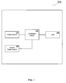
- FIG. 1 A schematic block diagram of a power control system in accordance with an embodiment of the present invention is shown in FIG. 1 .
- the power control system 200 includes a controlled switch 202 connected to a power source 204, a load 206 and a control power source 208. In operation, if the controlled switch 202 receives a signal from the control power source 208, the switch 202 connects or disconnects the load 206 from the power source 204.
- the power control system 200 is a subsystem of an aircraft electrical system.
- the power source 204 can be a generator, a battery or other AC or DC power sources.
- the load 206 can include aircraft flight instruments, essential systems such as landing gear, exterior lights, aircraft motor controls and the like, and/or passenger services such as lights, air conditioning and entertainment systems. In one embodiment, the loads range from requiring 1 to 400 amps. In another embodiment, the loads typically require 50 to 60 amps.
- the control power source 208 can be a signal generated in response to either automated systems or manual systems. In many embodiments, the control power source is capable of supplying an amount of current adequate to operate the controlled switch 202. In one embodiment, 6 to 7 amps from the control power source is sufficient to cause the controlled switch to connect or disconnect the load.
- the controlled switch is a contactor. In another embodiment, the controlled switch is a relay.
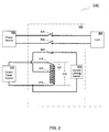
- FIG. 2 A schematic block diagram of a power control system including a controlled switch with a current limiting device in accordance with an embodiment of the present invention is shown in FIG. 2 .
- the power control system 300 includes a controlled switch 302, a power source 304, a load 306 and a control power source 308.
- the controlled switch 302 includes a pull-in coil 310, an economizer coil 312, an auxiliary switch 320, a first load switch 322, a second load switch 324, and a current limiting device 330.
- the economizer coil 312 includes a first end 314, a tap 316, and a second end 318, where the pull-in coil consists of the portion of the economizer coil extending from the second end 318 to the tap 316.
- the power source 304 is connected to the first load switch 322 and the second load switch 324.
- the first load switch 322 and the second load switch 324 are connected to the load 306.
- the control power source 308 is connected to both the first end 314 and the second end 318 of the economizer coil 312.
- the auxiliary switch and first and second load switches each include a switch arm (armature) and a switch contact.
- the tap 316 is connected to the auxiliary switch 320.
- the auxiliary switch 320 is normally closed and operates complimentary to the load switches that are normally open. The three switches are arranged such that all three are switched together.
- the auxiliary switch 320 is connected to the current limiting device 330.
- the first end 314 of the economizer coil 312 is connected to the current limiting device 330.
- the control power source 308 provides a voltage and switching current to the pull-in coil 310 at the second end 318.
- the current limiting device 330 has minimal resistance to current flowing through the device.
- nearly all of the switching current initially travels through the pull-in coil 310 and out of the tap 316, through the auxiliary switch 320 and current limiting device 330, and returns to the current power source 308 via the first end 314.
- the switching current provided by the control power source 308 enters at the first end 314 of the economizer coil 312 and returns via the second end 318.
- the initial switching current can be substantial in order to facilitate switching using the pull-in coil.
- the initial switching current or inrush current is approximately 6 to 7 amps.
- the pull-in coil acts as an electromagnet to create a force that physically switches or actuates the auxiliary switch and both of the load switches.
- the switching current supplied by the control power source can be reduced as the force required to hold the switch in the switched position is generally less than the force required to operate the switch. This is accomplished by opening the auxiliary contact in parallel to the hold coil and therefore placing the hold coil, with greater impedance, in the path of the current.
- the auxiliary switch can fail to open because of failed switch contacts, low voltage from the control power source or another reason.
- the current limiting device senses the continuing switching current and acts to limit the current flowing through the device.
- the current limiting device is a resettable fuse such as a thermistor or a polymer positive temperature coefficient (PPTC) fuse.
- the resettable fuse has a threshold or trip current such that when the threshold is exceeded for a predetermined period of time, the resettable fuse begins to heat up quickly.
- the heat changes the resistive properties of the resettable fuse such that the resistance of the device increases dramatically when the threshold is exceeded.
- the resistance increases by at least an order of magnitude.
- the resistance increases exponentially. However, when the current through the resettable fuse returns to a level below the threshold, the resistance of the fuse becomes minimal again as though it had been reset. In this way, the resettable fuse can be used any number of times to prevent switch failures from destroying the switching coil.
- the current limiting device can be a combination of components capable of comparing an input current level and a threshold over some period of time, and changing the overall impedance seen by the input current based on the comparison.
- the combination can include any number of devices including integrated circuits, processors and/or discrete devices coupled to one another.
- the threshold current must be exceeded for a period of time greater than 20 to 30 milliseconds before the resettable fuse heats up quickly to limit current flow.
- the resettable fuse can be a POLYFUSE® resettable positive temperature coefficient fuse such as any of the 60R250, 60R300, and 60R375 fuses made by Littlefuse, Inc. of Des Plaines, Illinois.
- the threshold current can be 5, 6, and 7.5 amps, respectively.
- the inrush current is greater than 6 to 7 amps.
- the threshold current must be exceeded for a period of time much greater than 20 to 30 milliseconds.
- two or more resettable fuses can be used together in parallel to increase the current capability and to extend the time for the combination of favor to substantially change their impedance.
- two or more resettable fuses can be used together in series.
- the controlled switch 202 functions in the same manner described above for the controlled switch 302 of FIG. 2 , in one embodiment of the invention.
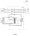
- FIG. 3 A schematic block diagram of a power control system including a controlled switch having normally closed load switches in accordance with an embodiment of the present invention is shown in FIG. 3 .
- the power control system 400 includes a controlled switch 402, a power source 404, a load 406 and a control power source 408.
- the controlled switch 402 includes a pull-in coil 410, an economizer coil 412, an auxiliary switch 420, a first load switch 422, a second load switch 424, and a current limiting device 430.
- the economizer coil 412 includes a first end 414, a tap 416, and a second end 418, where the pull-in coil consists of the portion of the economizer coil extending from the second end 418 to the tap 416.
- the power source 404 is connected to the first load switch 422 and the second load switch 424.
- the first load switch 422 and the second load switch 424 are connected to the load 406.
- the control power source 408 is connected to both the first end 414 and the second end 418 of the economizer coil 412.
- the auxiliary switch and first and second load switches each include a switch arm and a switch contact.
- the tap 416 is connected to the auxiliary switch 420.
- the auxiliary switch 420 and the load switches are normally closed. The three switches are arranged such that all three are switched together.
- the auxiliary switch is connected to the current limiting device 430.
- the first end 414 of the economizer coil 412 is connected to the current limiting device 430.
- the power control system 400 of FIG. 4 is identical to the embodiment shown in FIG. 3 , except that load switch 422 and load switch 424 are normally closed switches.
- the power control system 400 can operate as described previously for the embodiment shown in FIG. 3 .
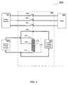
- the power control system 500 includes a controlled switch 502, a power source 504, a load 506 and a control power source 508.
- the controlled switch 502 includes a pull-in coil 510, an economizer coil 512, an auxiliary switch 520, a first load switch 522, a second load switch 524, a third load switch 526, and a current limiting device 530.
- the economizer coil 512 includes a first end 514, a tap 516, and a second end 518, where the pull-in coil consists of the portion of the economizer coil extending from the second end 518 to the tap 516.
- the power source 504 is connected to the first load switch 522, the second load switch 524, and the third load switch 526.
- the first load switch 522, the second load switch 524 and the third load switch 526 are connected to the load 506.
- the control power source 508 is connected to both the first end 514 and the second end 518 of the economizer coil 512.
- the auxiliary switch and first and second load switches each include a switch arm and a switch contact.
- the tap 516 is connected to the auxiliary switch 520.
- the auxiliary switch 520 is normally closed and the load switches are normally open.
- the four switches are arranged such that all three are switched together.
- the auxiliary switch is connected to the current limiting device 530.
- the first end 514 of the economizer coil 512 is connected to the current limiting device 530.
- the power control system 500 of FIG. 5 is nearly identical to the embodiment shown in FIG. 3 , except that it includes an additional load switch.
- the power control system 500 can operate as described previously for the embodiment shown in FIG. 3 .
- FIG. 5 A schematic block diagram of a power control system including a controlled switch having one load switch in accordance with an embodiment of the present invention is shown in FIG. 5 .
- the power control system 600 includes a controlled switch 602, a power source 604, a load 606 and a control power source 608.
- the controlled switch 602 includes a pull-in coil 610, an economizer coil 612, an auxiliary switch 620, a load switch 622, and a current limiting device 630.
- the economizer coil 612 includes a first end 614, a tap 616, and a second end 618, where the pull-in coil consists of the portion of the economizer coil extending from the second end 618 to the tap 616.
- the power source 604 is connected to the load switch 622.
- the load switch 622 is connected to the load 606.
- the control power source 608 is connected to both the first end 614 and the second end 618 of the economizer coil 612.
- the auxiliary switch and the load switch each include a switch arm and a switch contact.
- the tap 616 is connected to the auxiliary switch 620.
- the auxiliary switch 620 is normally closed and the load switch is normally open. The two switches are arranged such that they are both switched together.
- the auxiliary switch is connected to the current limiting device 630.
- the first end 614 of the economizer coil 612 is connected to the current limiting device 630.
- the power control system 600 of FIG. 5 is nearly identical to the embodiment shown in FIG. 2 , except that it includes only one load switch.
- the power control system 600 can operate as described previously for the embodiment shown in FIG. 2 .
- any number of load switches can be used in conjunction with at least one auxiliary switch in any number of arrangements of normally open or normally closed default switch settings.
- FIG. 6 A flowchart of a process for operating a controlled switch in accordance with an embodiment of the present invention is shown in FIG. 6 .
- the process 750 begins when it provides (752) switching current to a coil (e.g. a pull-in coil).
- the process then generates (754) a force for switching one or more load switches and an auxiliary switch.
- the force is proportional to, or a function of, the switching current.
- the process determines (756) whether the auxiliary switch failed to operate. In one embodiment, the determination is made based on the amount of current flowing through the current limiting device and the coil. If the auxiliary switch fails to operate, then the process limits (758) the current flowing through the coil and returns to determining (756) whether the auxiliary switch failed to open. In one embodiment, the current flowing through the coil is limited using a resettable fuse. If the auxiliary switch does not fail to operate, then the process allows (760) the full amount of current to flow through the coil.
- a coil e.g. a
Applications Claiming Priority (1)
| Application Number | Priority Date | Filing Date | Title |
|---|---|---|---|
| PCT/US2007/085026 WO2009064308A1 (en) | 2007-11-16 | 2007-11-16 | System and method for protecting a coil structure in a controlled switch |
Publications (3)
| Publication Number | Publication Date |
|---|---|
| EP2210262A1 EP2210262A1 (en) | 2010-07-28 |
| EP2210262A4 EP2210262A4 (en) | 2013-09-11 |
| EP2210262B1 true EP2210262B1 (en) | 2015-10-21 |
Family
ID=40638980
Family Applications (1)
| Application Number | Title | Priority Date | Filing Date |
|---|---|---|---|
| EP07864564.5A Not-in-force EP2210262B1 (en) | 2007-11-16 | 2007-11-16 | System and method for protecting a coil structure in a controlled switch |
Country Status (5)
| Country | Link |
|---|---|
| EP (1) | EP2210262B1 (xx) |
| CN (1) | CN101868842B (xx) |
| ES (1) | ES2553352T3 (xx) |
| HK (1) | HK1144331A1 (xx) |
| WO (1) | WO2009064308A1 (xx) |
Cited By (1)
| Publication number | Priority date | Publication date | Assignee | Title |
|---|---|---|---|---|
| FR3117664A1 (fr) * | 2020-12-16 | 2022-06-17 | Airbus Operations (S.A.S.) | Dispositif de commutation électromécanique d’un circuit électrique de puissance |
Families Citing this family (3)
| Publication number | Priority date | Publication date | Assignee | Title |
|---|---|---|---|---|
| FR2977706B1 (fr) * | 2011-07-04 | 2014-03-07 | Alstom Grid Ag | Dispositif de commande a ressort d'un appareillage de commutation haute ou moyenne tension |
| EP3525225B1 (en) * | 2018-02-08 | 2022-01-12 | Fico Triad, S.A. | Contactor system for a fluctuating dc power supply and method for stabilising a contactor system fed by a fluctuating dc power supply |
| FR3129767A1 (fr) | 2021-11-29 | 2023-06-02 | Airbus Operations (S.A.S.) | Dispositif de commutation électromécanique d’un circuit électrique de puissance comportant au moins un système de détection de la position en contact ou écartée d’une palette d’un contacteur |
Family Cites Families (13)
| Publication number | Priority date | Publication date | Assignee | Title |
|---|---|---|---|---|
| GB272012A (en) * | 1926-04-30 | 1927-06-09 | Igranic Electric Co Ltd | Improvements in or relating to electromagnetic switches operated by alternating current |
| FR2134081B1 (xx) * | 1971-04-19 | 1974-02-15 | Cem Comp Electro Mec | |
| JPS6142106A (ja) * | 1984-08-03 | 1986-02-28 | Matsushita Electric Works Ltd | 電磁コイル |
| JPS61116071A (ja) * | 1984-11-08 | 1986-06-03 | Nippon Denso Co Ltd | スタ−タ |
| JPS6220440U (xx) * | 1985-07-23 | 1987-02-06 | ||
| JPS62111308A (ja) * | 1985-11-09 | 1987-05-22 | Alps Electric Co Ltd | モ−タアクチユエ−タ |
| CN2030390U (zh) * | 1988-03-26 | 1989-01-04 | 张云祥 | 具有断相保护装置的节电开关 |
| US5120908A (en) * | 1990-11-01 | 1992-06-09 | Gazelle Graphic Systems Inc. | Electromagnetic position transducer |
| US5530613A (en) * | 1994-06-01 | 1996-06-25 | Eaton Corporation | Current limiting circuit controller |
| EP0800193B1 (en) * | 1996-04-04 | 2002-02-20 | Denso Corporation | Power supply terminal structure for starter magnet switch |
| CN2332060Y (zh) * | 1997-04-24 | 1999-08-04 | 乐清市东方节能电器厂 | 消声节能交流接触器 |
| CN100463320C (zh) * | 2003-01-08 | 2009-02-18 | 钱本宁 | 主控自动电器关机装置 |
| US20050180078A1 (en) * | 2004-02-13 | 2005-08-18 | Adams Rite Aerospace, Inc. | Solenoid protection method and apparatus |
-
2007
- 2007-11-16 ES ES07864564.5T patent/ES2553352T3/es active Active
- 2007-11-16 WO PCT/US2007/085026 patent/WO2009064308A1/en active Application Filing
- 2007-11-16 EP EP07864564.5A patent/EP2210262B1/en not_active Not-in-force
- 2007-11-16 CN CN200780101562.3A patent/CN101868842B/zh not_active Expired - Fee Related
-
2010
- 2010-11-23 HK HK10110889.1A patent/HK1144331A1/xx not_active IP Right Cessation
Cited By (3)
| Publication number | Priority date | Publication date | Assignee | Title |
|---|---|---|---|---|
| FR3117664A1 (fr) * | 2020-12-16 | 2022-06-17 | Airbus Operations (S.A.S.) | Dispositif de commutation électromécanique d’un circuit électrique de puissance |
| EP4016570A1 (fr) * | 2020-12-16 | 2022-06-22 | Airbus Operations SAS | Dispositif de commutation électromécanique d'un circuit électrique de puissance |
| US11784484B2 (en) | 2020-12-16 | 2023-10-10 | Airbus Operations Sas | Electromechanical switching device of an electric power circuit |
Also Published As
| Publication number | Publication date |
|---|---|
| ES2553352T3 (es) | 2015-12-07 |
| WO2009064308A1 (en) | 2009-05-22 |
| CN101868842A (zh) | 2010-10-20 |
| EP2210262A4 (en) | 2013-09-11 |
| CN101868842B (zh) | 2013-06-05 |
| EP2210262A1 (en) | 2010-07-28 |
| HK1144331A1 (en) | 2011-02-11 |
Similar Documents
| Publication | Publication Date | Title |
|---|---|---|
| US7710697B2 (en) | Hybrid system for electronically resetable circuit protection | |
| US7586725B2 (en) | Method of providing a secondary means of overload protection and leakage current protection in applications using solid state power controllers | |
| US6490141B2 (en) | Power distribution system | |
| US6738246B1 (en) | Electrical circuit breaker for protecting against overcurrents | |
| JPH11512599A (ja) | 過電流保護回路 | |
| JP2010530208A (ja) | 暖房・換気・空調システムにおける微小電子機械システムベースのスイッチング | |
| EP2210262B1 (en) | System and method for protecting a coil structure in a controlled switch | |
| EP1039611B1 (en) | High-voltage switch gear protection circuit | |
| CN109689438B (zh) | 继电器装置 | |
| PL207875B1 (pl) | Automatyczne urządzenie zabezpieczające i przełączające między obwodami | |
| EP0278719A2 (en) | Solid state current limited power controller for DC circuits | |
| US7995320B2 (en) | System and method for protecting a coil structure in a controlled switch | |
| CN109801817B (zh) | 混合电路配置 | |
| US6597154B2 (en) | Electrical energy distribution system and contactor for such a system | |
| JP2022035412A (ja) | 電池パック | |
| US7345259B2 (en) | Circuit arrangement and method for preventing overheating of a cooking appliance | |
| KR100378627B1 (ko) | 변압기의 전류 생성을 제한하는 회로 | |
| WO2007121053A2 (en) | Open neutral detection circuit | |
| JP2020072010A (ja) | 電気ヒータ装置 | |
| US5875641A (en) | Contactor with solid state protection circuit for a vapor compression air conditioner | |
| JP2000092690A (ja) | 複数の電気負荷用の安全装置及び複数の電気負荷の給電遮断方法 | |
| JP3833747B2 (ja) | 節電装置 | |
| US11984290B2 (en) | Circuit breaker | |
| US20220139644A1 (en) | Circuit breaker | |
| JP2986424B2 (ja) | 電圧制御装置 |
Legal Events
| Date | Code | Title | Description |
|---|---|---|---|
| PUAI | Public reference made under article 153(3) epc to a published international application that has entered the european phase |
Free format text: ORIGINAL CODE: 0009012 |
|
| 17P | Request for examination filed |
Effective date: 20100512 |
|
| AK | Designated contracting states |
Kind code of ref document: A1 Designated state(s): AT BE BG CH CY CZ DE DK EE ES FI FR GB GR HU IE IS IT LI LT LU LV MC MT NL PL PT RO SE SI SK TR |
|
| AX | Request for extension of the european patent |
Extension state: AL BA HR MK RS |
|
| DAX | Request for extension of the european patent (deleted) | ||
| REG | Reference to a national code |
Ref country code: DE Ref legal event code: R079 Ref document number: 602007043634 Country of ref document: DE Free format text: PREVIOUS MAIN CLASS: H01H0019560000 Ipc: H01H0047060000 |
|
| A4 | Supplementary search report drawn up and despatched |
Effective date: 20130808 |
|
| RIC1 | Information provided on ipc code assigned before grant |
Ipc: H01H 47/06 20060101AFI20130802BHEP |
|
| 17Q | First examination report despatched |
Effective date: 20140214 |
|
| GRAP | Despatch of communication of intention to grant a patent |
Free format text: ORIGINAL CODE: EPIDOSNIGR1 |
|
| INTG | Intention to grant announced |
Effective date: 20150511 |
|
| RIN1 | Information on inventor provided before grant (corrected) |
Inventor name: TOFIGH, FARSHID Inventor name: KRUPPA, OTMAR |
|
| GRAS | Grant fee paid |
Free format text: ORIGINAL CODE: EPIDOSNIGR3 |
|
| GRAA | (expected) grant |
Free format text: ORIGINAL CODE: 0009210 |
|
| AK | Designated contracting states |
Kind code of ref document: B1 Designated state(s): AT BE BG CH CY CZ DE DK EE ES FI FR GB GR HU IE IS IT LI LT LU LV MC MT NL PL PT RO SE SI SK TR |
|
| REG | Reference to a national code |
Ref country code: GB Ref legal event code: FG4D Ref country code: NL Ref legal event code: MP Effective date: 20151021 |
|
| REG | Reference to a national code |
Ref country code: CH Ref legal event code: EP |
|
| REG | Reference to a national code |
Ref country code: AT Ref legal event code: REF Ref document number: 757068 Country of ref document: AT Kind code of ref document: T Effective date: 20151115 |
|
| REG | Reference to a national code |
Ref country code: FR Ref legal event code: PLFP Year of fee payment: 9 |
|
| REG | Reference to a national code |
Ref country code: IE Ref legal event code: FG4D |
|
| REG | Reference to a national code |
Ref country code: DE Ref legal event code: R096 Ref document number: 602007043634 Country of ref document: DE |
|
| REG | Reference to a national code |
Ref country code: ES Ref legal event code: FG2A Ref document number: 2553352 Country of ref document: ES Kind code of ref document: T3 Effective date: 20151207 |
|
| REG | Reference to a national code |
Ref country code: LT Ref legal event code: MG4D |
|
| REG | Reference to a national code |
Ref country code: AT Ref legal event code: MK05 Ref document number: 757068 Country of ref document: AT Kind code of ref document: T Effective date: 20151021 |
|
| PG25 | Lapsed in a contracting state [announced via postgrant information from national office to epo] |
Ref country code: LT Free format text: LAPSE BECAUSE OF FAILURE TO SUBMIT A TRANSLATION OF THE DESCRIPTION OR TO PAY THE FEE WITHIN THE PRESCRIBED TIME-LIMIT Effective date: 20151021 Ref country code: IS Free format text: LAPSE BECAUSE OF FAILURE TO SUBMIT A TRANSLATION OF THE DESCRIPTION OR TO PAY THE FEE WITHIN THE PRESCRIBED TIME-LIMIT Effective date: 20160221 Ref country code: NL Free format text: LAPSE BECAUSE OF FAILURE TO SUBMIT A TRANSLATION OF THE DESCRIPTION OR TO PAY THE FEE WITHIN THE PRESCRIBED TIME-LIMIT Effective date: 20151021 Ref country code: IT Free format text: LAPSE BECAUSE OF FAILURE TO SUBMIT A TRANSLATION OF THE DESCRIPTION OR TO PAY THE FEE WITHIN THE PRESCRIBED TIME-LIMIT Effective date: 20151021 |
|
| PG25 | Lapsed in a contracting state [announced via postgrant information from national office to epo] |
Ref country code: PT Free format text: LAPSE BECAUSE OF FAILURE TO SUBMIT A TRANSLATION OF THE DESCRIPTION OR TO PAY THE FEE WITHIN THE PRESCRIBED TIME-LIMIT Effective date: 20160222 Ref country code: SE Free format text: LAPSE BECAUSE OF FAILURE TO SUBMIT A TRANSLATION OF THE DESCRIPTION OR TO PAY THE FEE WITHIN THE PRESCRIBED TIME-LIMIT Effective date: 20151021 Ref country code: GR Free format text: LAPSE BECAUSE OF FAILURE TO SUBMIT A TRANSLATION OF THE DESCRIPTION OR TO PAY THE FEE WITHIN THE PRESCRIBED TIME-LIMIT Effective date: 20160122 Ref country code: FI Free format text: LAPSE BECAUSE OF FAILURE TO SUBMIT A TRANSLATION OF THE DESCRIPTION OR TO PAY THE FEE WITHIN THE PRESCRIBED TIME-LIMIT Effective date: 20151021 Ref country code: LV Free format text: LAPSE BECAUSE OF FAILURE TO SUBMIT A TRANSLATION OF THE DESCRIPTION OR TO PAY THE FEE WITHIN THE PRESCRIBED TIME-LIMIT Effective date: 20151021 Ref country code: PL Free format text: LAPSE BECAUSE OF FAILURE TO SUBMIT A TRANSLATION OF THE DESCRIPTION OR TO PAY THE FEE WITHIN THE PRESCRIBED TIME-LIMIT Effective date: 20151021 Ref country code: AT Free format text: LAPSE BECAUSE OF FAILURE TO SUBMIT A TRANSLATION OF THE DESCRIPTION OR TO PAY THE FEE WITHIN THE PRESCRIBED TIME-LIMIT Effective date: 20151021 |
|
| REG | Reference to a national code |
Ref country code: CH Ref legal event code: PL |
|
| REG | Reference to a national code |
Ref country code: DE Ref legal event code: R097 Ref document number: 602007043634 Country of ref document: DE |
|
| PG25 | Lapsed in a contracting state [announced via postgrant information from national office to epo] |
Ref country code: CZ Free format text: LAPSE BECAUSE OF FAILURE TO SUBMIT A TRANSLATION OF THE DESCRIPTION OR TO PAY THE FEE WITHIN THE PRESCRIBED TIME-LIMIT Effective date: 20151021 Ref country code: LI Free format text: LAPSE BECAUSE OF NON-PAYMENT OF DUE FEES Effective date: 20151130 Ref country code: MC Free format text: LAPSE BECAUSE OF FAILURE TO SUBMIT A TRANSLATION OF THE DESCRIPTION OR TO PAY THE FEE WITHIN THE PRESCRIBED TIME-LIMIT Effective date: 20151021 Ref country code: CH Free format text: LAPSE BECAUSE OF NON-PAYMENT OF DUE FEES Effective date: 20151130 |
|
| REG | Reference to a national code |
Ref country code: IE Ref legal event code: MM4A |
|
| PLBE | No opposition filed within time limit |
Free format text: ORIGINAL CODE: 0009261 |
|
| STAA | Information on the status of an ep patent application or granted ep patent |
Free format text: STATUS: NO OPPOSITION FILED WITHIN TIME LIMIT |
|
| PG25 | Lapsed in a contracting state [announced via postgrant information from national office to epo] |
Ref country code: SK Free format text: LAPSE BECAUSE OF FAILURE TO SUBMIT A TRANSLATION OF THE DESCRIPTION OR TO PAY THE FEE WITHIN THE PRESCRIBED TIME-LIMIT Effective date: 20151021 Ref country code: RO Free format text: LAPSE BECAUSE OF FAILURE TO SUBMIT A TRANSLATION OF THE DESCRIPTION OR TO PAY THE FEE WITHIN THE PRESCRIBED TIME-LIMIT Effective date: 20151021 Ref country code: DK Free format text: LAPSE BECAUSE OF FAILURE TO SUBMIT A TRANSLATION OF THE DESCRIPTION OR TO PAY THE FEE WITHIN THE PRESCRIBED TIME-LIMIT Effective date: 20151021 Ref country code: EE Free format text: LAPSE BECAUSE OF FAILURE TO SUBMIT A TRANSLATION OF THE DESCRIPTION OR TO PAY THE FEE WITHIN THE PRESCRIBED TIME-LIMIT Effective date: 20151021 |
|
| 26N | No opposition filed |
Effective date: 20160722 |
|
| PG25 | Lapsed in a contracting state [announced via postgrant information from national office to epo] |
Ref country code: IE Free format text: LAPSE BECAUSE OF NON-PAYMENT OF DUE FEES Effective date: 20151116 |
|
| REG | Reference to a national code |
Ref country code: FR Ref legal event code: PLFP Year of fee payment: 10 |
|
| PG25 | Lapsed in a contracting state [announced via postgrant information from national office to epo] |
Ref country code: SI Free format text: LAPSE BECAUSE OF FAILURE TO SUBMIT A TRANSLATION OF THE DESCRIPTION OR TO PAY THE FEE WITHIN THE PRESCRIBED TIME-LIMIT Effective date: 20151021 |
|
| PG25 | Lapsed in a contracting state [announced via postgrant information from national office to epo] |
Ref country code: BE Free format text: LAPSE BECAUSE OF FAILURE TO SUBMIT A TRANSLATION OF THE DESCRIPTION OR TO PAY THE FEE WITHIN THE PRESCRIBED TIME-LIMIT Effective date: 20151021 |
|
| PG25 | Lapsed in a contracting state [announced via postgrant information from national office to epo] |
Ref country code: BG Free format text: LAPSE BECAUSE OF FAILURE TO SUBMIT A TRANSLATION OF THE DESCRIPTION OR TO PAY THE FEE WITHIN THE PRESCRIBED TIME-LIMIT Effective date: 20151021 Ref country code: HU Free format text: LAPSE BECAUSE OF FAILURE TO SUBMIT A TRANSLATION OF THE DESCRIPTION OR TO PAY THE FEE WITHIN THE PRESCRIBED TIME-LIMIT; INVALID AB INITIO Effective date: 20071116 |
|
| PG25 | Lapsed in a contracting state [announced via postgrant information from national office to epo] |
Ref country code: CY Free format text: LAPSE BECAUSE OF FAILURE TO SUBMIT A TRANSLATION OF THE DESCRIPTION OR TO PAY THE FEE WITHIN THE PRESCRIBED TIME-LIMIT Effective date: 20151021 |
|
| PG25 | Lapsed in a contracting state [announced via postgrant information from national office to epo] |
Ref country code: MT Free format text: LAPSE BECAUSE OF FAILURE TO SUBMIT A TRANSLATION OF THE DESCRIPTION OR TO PAY THE FEE WITHIN THE PRESCRIBED TIME-LIMIT Effective date: 20151021 Ref country code: TR Free format text: LAPSE BECAUSE OF FAILURE TO SUBMIT A TRANSLATION OF THE DESCRIPTION OR TO PAY THE FEE WITHIN THE PRESCRIBED TIME-LIMIT Effective date: 20151021 |
|
| REG | Reference to a national code |
Ref country code: FR Ref legal event code: PLFP Year of fee payment: 11 |
|
| PG25 | Lapsed in a contracting state [announced via postgrant information from national office to epo] |
Ref country code: LU Free format text: LAPSE BECAUSE OF NON-PAYMENT OF DUE FEES Effective date: 20151116 |
|
| PGFP | Annual fee paid to national office [announced via postgrant information from national office to epo] |
Ref country code: GB Payment date: 20211129 Year of fee payment: 15 Ref country code: ES Payment date: 20211201 Year of fee payment: 15 Ref country code: FR Payment date: 20211124 Year of fee payment: 15 Ref country code: DE Payment date: 20211126 Year of fee payment: 15 |
|
| REG | Reference to a national code |
Ref country code: DE Ref legal event code: R119 Ref document number: 602007043634 Country of ref document: DE |
|
| GBPC | Gb: european patent ceased through non-payment of renewal fee |
Effective date: 20221116 |
|
| PG25 | Lapsed in a contracting state [announced via postgrant information from national office to epo] |
Ref country code: GB Free format text: LAPSE BECAUSE OF NON-PAYMENT OF DUE FEES Effective date: 20221116 Ref country code: DE Free format text: LAPSE BECAUSE OF NON-PAYMENT OF DUE FEES Effective date: 20230601 |
|
| PG25 | Lapsed in a contracting state [announced via postgrant information from national office to epo] |
Ref country code: FR Free format text: LAPSE BECAUSE OF NON-PAYMENT OF DUE FEES Effective date: 20221130 |
|
| REG | Reference to a national code |
Ref country code: ES Ref legal event code: FD2A Effective date: 20240102 |
|
| PG25 | Lapsed in a contracting state [announced via postgrant information from national office to epo] |
Ref country code: ES Free format text: LAPSE BECAUSE OF NON-PAYMENT OF DUE FEES Effective date: 20221117 |
|
| PG25 | Lapsed in a contracting state [announced via postgrant information from national office to epo] |
Ref country code: ES Free format text: LAPSE BECAUSE OF NON-PAYMENT OF DUE FEES Effective date: 20221117 |