EP2210036B1 - Lighting device and method of making - Google Patents
Lighting device and method of making Download PDFInfo
- Publication number
- EP2210036B1 EP2210036B1 EP08837037.4A EP08837037A EP2210036B1 EP 2210036 B1 EP2210036 B1 EP 2210036B1 EP 08837037 A EP08837037 A EP 08837037A EP 2210036 B1 EP2210036 B1 EP 2210036B1
- Authority
- EP
- European Patent Office
- Prior art keywords
- light
- group
- white
- lighting device
- wavelength
- Prior art date
- Legal status (The legal status is an assumption and is not a legal conclusion. Google has not performed a legal analysis and makes no representation as to the accuracy of the status listed.)
- Active
Links
Images


Classifications
-
- F—MECHANICAL ENGINEERING; LIGHTING; HEATING; WEAPONS; BLASTING
- F21—LIGHTING
- F21K—NON-ELECTRIC LIGHT SOURCES USING LUMINESCENCE; LIGHT SOURCES USING ELECTROCHEMILUMINESCENCE; LIGHT SOURCES USING CHARGES OF COMBUSTIBLE MATERIAL; LIGHT SOURCES USING SEMICONDUCTOR DEVICES AS LIGHT-GENERATING ELEMENTS; LIGHT SOURCES NOT OTHERWISE PROVIDED FOR
- F21K9/00—Light sources using semiconductor devices as light-generating elements, e.g. using light-emitting diodes [LED] or lasers
- F21K9/20—Light sources comprising attachment means
- F21K9/23—Retrofit light sources for lighting devices with a single fitting for each light source, e.g. for substitution of incandescent lamps with bayonet or threaded fittings
- F21K9/233—Retrofit light sources for lighting devices with a single fitting for each light source, e.g. for substitution of incandescent lamps with bayonet or threaded fittings specially adapted for generating a spot light distribution, e.g. for substitution of reflector lamps
-
- H—ELECTRICITY
- H05—ELECTRIC TECHNIQUES NOT OTHERWISE PROVIDED FOR
- H05B—ELECTRIC HEATING; ELECTRIC LIGHT SOURCES NOT OTHERWISE PROVIDED FOR; CIRCUIT ARRANGEMENTS FOR ELECTRIC LIGHT SOURCES, IN GENERAL
- H05B45/00—Circuit arrangements for operating light-emitting diodes [LED]
- H05B45/20—Controlling the colour of the light
-
- F—MECHANICAL ENGINEERING; LIGHTING; HEATING; WEAPONS; BLASTING
- F21—LIGHTING
- F21V—FUNCTIONAL FEATURES OR DETAILS OF LIGHTING DEVICES OR SYSTEMS THEREOF; STRUCTURAL COMBINATIONS OF LIGHTING DEVICES WITH OTHER ARTICLES, NOT OTHERWISE PROVIDED FOR
- F21V23/00—Arrangement of electric circuit elements in or on lighting devices
- F21V23/04—Arrangement of electric circuit elements in or on lighting devices the elements being switches
- F21V23/0442—Arrangement of electric circuit elements in or on lighting devices the elements being switches activated by means of a sensor, e.g. motion or photodetectors
- F21V23/0457—Arrangement of electric circuit elements in or on lighting devices the elements being switches activated by means of a sensor, e.g. motion or photodetectors the sensor sensing the operating status of the lighting device, e.g. to detect failure of a light source or to provide feedback to the device
-
- F—MECHANICAL ENGINEERING; LIGHTING; HEATING; WEAPONS; BLASTING
- F21—LIGHTING
- F21Y—INDEXING SCHEME ASSOCIATED WITH SUBCLASSES F21K, F21L, F21S and F21V, RELATING TO THE FORM OR THE KIND OF THE LIGHT SOURCES OR OF THE COLOUR OF THE LIGHT EMITTED
- F21Y2113/00—Combination of light sources
- F21Y2113/10—Combination of light sources of different colours
- F21Y2113/13—Combination of light sources of different colours comprising an assembly of point-like light sources
-
- F—MECHANICAL ENGINEERING; LIGHTING; HEATING; WEAPONS; BLASTING
- F21—LIGHTING
- F21Y—INDEXING SCHEME ASSOCIATED WITH SUBCLASSES F21K, F21L, F21S and F21V, RELATING TO THE FORM OR THE KIND OF THE LIGHT SOURCES OR OF THE COLOUR OF THE LIGHT EMITTED
- F21Y2115/00—Light-generating elements of semiconductor light sources
- F21Y2115/10—Light-emitting diodes [LED]
-
- H—ELECTRICITY
- H01—ELECTRIC ELEMENTS
- H01L—SEMICONDUCTOR DEVICES NOT COVERED BY CLASS H10
- H01L2224/00—Indexing scheme for arrangements for connecting or disconnecting semiconductor or solid-state bodies and methods related thereto as covered by H01L24/00
- H01L2224/01—Means for bonding being attached to, or being formed on, the surface to be connected, e.g. chip-to-package, die-attach, "first-level" interconnects; Manufacturing methods related thereto
- H01L2224/42—Wire connectors; Manufacturing methods related thereto
- H01L2224/47—Structure, shape, material or disposition of the wire connectors after the connecting process
- H01L2224/48—Structure, shape, material or disposition of the wire connectors after the connecting process of an individual wire connector
- H01L2224/4805—Shape
- H01L2224/4809—Loop shape
- H01L2224/48091—Arched
-
- H—ELECTRICITY
- H01—ELECTRIC ELEMENTS
- H01L—SEMICONDUCTOR DEVICES NOT COVERED BY CLASS H10
- H01L2224/00—Indexing scheme for arrangements for connecting or disconnecting semiconductor or solid-state bodies and methods related thereto as covered by H01L24/00
- H01L2224/01—Means for bonding being attached to, or being formed on, the surface to be connected, e.g. chip-to-package, die-attach, "first-level" interconnects; Manufacturing methods related thereto
- H01L2224/42—Wire connectors; Manufacturing methods related thereto
- H01L2224/47—Structure, shape, material or disposition of the wire connectors after the connecting process
- H01L2224/48—Structure, shape, material or disposition of the wire connectors after the connecting process of an individual wire connector
- H01L2224/481—Disposition
- H01L2224/48151—Connecting between a semiconductor or solid-state body and an item not being a semiconductor or solid-state body, e.g. chip-to-substrate, chip-to-passive
- H01L2224/48221—Connecting between a semiconductor or solid-state body and an item not being a semiconductor or solid-state body, e.g. chip-to-substrate, chip-to-passive the body and the item being stacked
- H01L2224/48245—Connecting between a semiconductor or solid-state body and an item not being a semiconductor or solid-state body, e.g. chip-to-substrate, chip-to-passive the body and the item being stacked the item being metallic
- H01L2224/48247—Connecting between a semiconductor or solid-state body and an item not being a semiconductor or solid-state body, e.g. chip-to-substrate, chip-to-passive the body and the item being stacked the item being metallic connecting the wire to a bond pad of the item
-
- H—ELECTRICITY
- H01—ELECTRIC ELEMENTS
- H01L—SEMICONDUCTOR DEVICES NOT COVERED BY CLASS H10
- H01L2924/00—Indexing scheme for arrangements or methods for connecting or disconnecting semiconductor or solid-state bodies as covered by H01L24/00
- H01L2924/10—Details of semiconductor or other solid state devices to be connected
- H01L2924/11—Device type
- H01L2924/13—Discrete devices, e.g. 3 terminal devices
- H01L2924/1304—Transistor
- H01L2924/1306—Field-effect transistor [FET]
- H01L2924/13091—Metal-Oxide-Semiconductor Field-Effect Transistor [MOSFET]
-
- H—ELECTRICITY
- H05—ELECTRIC TECHNIQUES NOT OTHERWISE PROVIDED FOR
- H05B—ELECTRIC HEATING; ELECTRIC LIGHT SOURCES NOT OTHERWISE PROVIDED FOR; CIRCUIT ARRANGEMENTS FOR ELECTRIC LIGHT SOURCES, IN GENERAL
- H05B45/00—Circuit arrangements for operating light-emitting diodes [LED]
- H05B45/20—Controlling the colour of the light
- H05B45/28—Controlling the colour of the light using temperature feedback
Definitions
- the present inventive subject matter relates to lighting devices and methods of making them.
- the present inventive subject matter relates to a lighting device which includes one or more non-white light sources and at least two supplemental light emitters which improve the CRI Ra of the light emitted from the lighting device.
- some embodiments of the present inventive subject matter provide lighting devices which respectively emit light of high CRI Ra in a wide range of color temperatures.
- CRI Ra Color reproduction is typically measured using the Color Rendering Index (CRI Ra).
- CRI Ra is a modified average of the relative measurements of how the color rendition of an illumination system compares to that of a reference radiator when illuminating eight reference colors, i.e., it is a relative measure of the shift in surface color of an object when lit by a particular lamp.
- the CRI Ra equals 100 if the color coordinates of a set of test colors being illuminated by the illumination system are the same as the coordinates of the same test colors being irradiated by the reference radiator.
- Daylight has a high CRI (Ra of approximately 100), with incandescent bulbs also being relatively close (Ra greater than 95), and fluorescent lighting being less accurate (typical Ra of 70-80).
- CRI CRI
- Sodium lights are used, e.g., to light highways - driver response time, however, significantly decreases with lower CRI Ra values (for any given brightness, legibility decreases with lower CRI Ra).
- CRI Ra Commission Internationale de l'Eclairage. Method of Measuring and Specifying Colour Rendering Properties of Light Sources, CIE 13.3 (1995 ) for further information on CRI.
- the CIE Chromaticity Diagrams map out the human color perception in terms of two CIE parameters x and y (in the case of the 1931 diagram) or u' and v' (in the case of the 1976 diagram).
- the spectral colors are distributed around the edge of the outlined space, which includes all of the hues perceived by the human eye.
- the boundary line represents maximum saturation for the spectral colors.
- the 1976 CIE Chromaticity Diagram is similar to the 1931 Diagram, except that the 1976 Diagram has been modified such that similar distances on the Diagram represent similar perceived differences in color.
- the 1976 CIE Diagram includes temperature listings along the blackbody locus. These temperature listings show the color path of a blackbody radiator that is caused to increase to such temperatures. As a heated object becomes incandescent, it first glows reddish, then yellowish, then white, and finally blueish. This occurs because the wavelength associated with the peak radiation of the blackbody radiator becomes progressively shorter with increased temperature, consistent with the Wien Displacement Law. Illuminants which produce light which is on or near the blackbody locus can thus be described in terms of their color temperature.
- Light emitting diode lamps have been demonstrated to be able to produce white light with component efficacy >150L/W and are anticipated to be the predominant lighting devices within the next decade. See e.g., Narukawa, Narita, Sakamoto, Deguchi, Yamada, Mukai: "Ultra-High Efficiency White Light Emitting Diodes” Jpn. J. Appl. Phys. 32 (1993) L9 Vol. 45, No. 41, 2006, pp. L1084-L10-86 ; and on the World Wide Web nichia.com/about_nichia/2006/2006_122001.html.
- LEDs which combine blue emitters + YAG:Ce or BOSE phosphors or Red, Green and Blue InGaN / AlInGaP LEDs; or UV LED excited RGB phosphors. These methods have good efficacy but only medium CRI or very good CRI and low efficacy. The efficacy and CRI tradeoff in LEDs is also an issue in the lighting industry with regard to fluorescent illumination. See Zukauskas A., Shur M.S., Cacka R. "Introduction to Solid-State Lighting” 2002, ISBN 0-471-215574-0, section 6.1.1 page 118 .
- luminaires use yellow sodium light
- the majority of illumination uses light that is colored more naturally, similar to the color or color temperature of natural sources, including the color emitted by burning fuels, incandescent sources or daylight.
- white light or “whiteness” does not clearly cover this range of colors as it is plain that a candle flame and other incandescent sources are yellowish, i.e., not completely white. Therefore the color of illumination is generally and better defined in terms of correlated color temperature (CCT) and needs to also be defined as to its proximity to the planckian black body locus (BBL) in addition to its CCT.
- CCT correlated color temperature
- BBL planckian black body locus
- CRI Ra is the most commonly used metric for measuring color quality today. This CIE standard method (see, e.g., Commission Internationale de l'Eclairage. Method of Measuring and Specifying Colour Rendering Properties of Light Sources, CIE 13.3 (1995 )) compares the rendered colors of 8 reference color swatches illuminated by the test illumination to the rendered color of the same swatches illuminated by reference light. Illumination with a CRI Ra of less than 50 is very poor and only used in applications where there is no alternative for economic issues. Lights with a CRI Ra between 70 and 80 have application for general illumination where the colors of objects are not important. For some general interior illumination, a CRI Ra >80 is acceptable.
- a light with color coordinates within 4 MacAdam step ellipses of the planckian locus and a CRI Ra > 85 is more suitable for general illumination purposes.
- CRI Ra > 90 is preferable and provides greater color quality.
- Some of the most commonly used LEDs in solid state lighting are phosphor excited LEDs.
- a yellow phosphor typically YAG:Ce or BOSE
- BOSE blue InGaN LED die.
- the resultant mix of yellow phosphor emitted light and some leaking blue light combines to produce a white light.
- This method typically produces light >5000K CCT and typically has a CRI Ra of between ⁇ 70 and 80.
- an orange phosphor or a mix of red and yellow phosphor can be used.
- R+G+B lights also suffer from lower CRI Ra, in part due to the narrow full width at half maximum (FWHM) values of the green and red LEDs.
- Pure color LEDs i.e., saturated LEDs usually have a FWHM value in the range of from about 15 nm to about 30 nm.
- UV based LEDs combined with red, green and blue phosphors offer quite good CRI Ra, similar to fluorescent lighting. Due to increased Stokes losses, however, they also have lower efficacies.
- the highest efficiency LEDs today are blue LEDs made from InGaN. Commercially available devices have external quantum efficiency (EQE) as great as 60%.
- the highest efficiency phosphors suitable for LEDs today are YAG:Ce and BOSE phosphor with a peak emission around 555nm.
- YAG:Ce has a quantum efficiency of >90% and is an extremely robust and well tested phosphor. Using this approach, almost any color along the tie line between blue and yellow is possible as shown in Fig. 2 .
- White LED lamps made with this method typically have a CRI Ra of between 70 and 80.
- the primary omission from the spectrum being red color components and, to some extent, cyan.
- Red AlInGaP LEDs have very high internal quantum efficiency, but due to the large refractive index mismatch between AlInGaP and suitable encapsulant materials, a lot of light is lost due to total internal reflection (TIR). Regardless, red and orange packaged LEDs are commercially available with efficacies higher than 60L/W.
- LEDs Light Emitting Diodes
- U.S. Patent No. 7,095,056 discloses a white light emitting device and method that generate light by combining light produced by a white light source (i.e., light which is perceived as white) with light produced by at least one supplemental light emitting diode (LED).
- a white light source i.e., light which is perceived as white
- LED supplemental light emitting diode
- Vitta '056 provides a device which comprises a light source which emits light which would be perceived as white, a first supplemental light emitting diode (LED) that produces cyan light, and a second supplemental LED that produces red light, wherein the light emitted from the device comprises a combination of the light produced by the white light source, the first supplemental LED, and the second supplemental LED. While the arrangement disclosed in Vitta '056 allows the CCT to be changed, the CRI and the usefulness of the device reduces significantly at lower color temperatures, making this arrangement generally undesirable for indoor general illumination.
- Another white light emitting device is known from US 2005/0117334 A1 , wherein a device is disclosed comprising a first blue LED, a second LED emitting blue-green light, a third LED emitting red light and a YAG phosphor excited by both said first blue LED and said second blue-green LED.
- the resulting mixed white light has an excellent color rendering index.
- the whiteness of the emission from a lighting device is somewhat subjective. In terms of illumination, it is generally defined as to its proximity to the planckian blackbody locus. Schubert, in his book Light-Emitting Diodes, second edition, on page 325 states, "the pleasantness and quality of white illumination decreases rapidly if the chromaticity point of the illumination source deviates from the planckian locus by a distance of greater than 0.01 in the x,y chromaticity system. This corresponds to the distance of about 4 MacAdam ellipses, a standard employed by the lighting industry. See Duggal A. R. "Organic electroluminescent devices for solid-state lighting" in Organic Electroluminescence edited by Z.H.
- a lighting device which has color coordinates that are within 4 MacAdam step ellipses of the planckian locus and which has a CRI Ra > 80 is generally acceptable as a white light for illumination purposes.
- a lighting device which has color coordinates within 7 MacAdam ellipses of the planckian locus and which has a CRI Ra > 70 is used as the minimum standards for many other white lighting devices including CFL and SSL (solid state lighting) lighting devices. (see DOE - Energy Star Program requirements for SSL Luminaires, 2006 ).
- the distance a color point is from the BBL can also be more easily defined in terms of Eu'v'. This is the length of a line between the color point of the lighting device and the nearest point on the BBL defined in the CIE76 color space.
- a Eu'v' of 0.0012 is approximately equivalent to a single step MacAdam ellipse in the area near the BBL.
- General illumination generally has a color temperature between 2,000 K and 10,000 K, with the majority of lighting devices for general illumination being between 2,700 K and 6,500 K.
- the white area is within Eu'v' 0.01 (approximately 8 MacAdam ellipses) of the planckian locus and between 2,500 K and 10,000 K, and is shown in Fig. 1 .
- the present inventive subject matter provides color combinations of light emitters, e.g., LEDs, that can be constructed into lighting devices with high CRI, warm and cool color temperatures and/or variable color temperatures.
- light emitters e.g., LEDs
- the present inventive subject matter provides lighting devices which comprise at least one or more non-white light sources (e.g., non-saturated phosphor LEDs which emit off-white or low to medium purity color), a second light source emitting light in the red to orange part of the color spectrum and a third light source emitting light in the blue to green spectrum.
- the mixed light from the three (or more) sources forms a light spectrum which is perceived as being within 4 MacAdam Ellipses of the planckian blackbody locus and with a CRI Ra of greater than 90.
- a lighting device where the color temperature can be changed while maintaining a very high CRI by using at least a fourth light source that emits light perceived as either white and/or off-white and/or purple-ish and/or blueish-purple and/or blueish-green light.
- the phosphor-LED is yellowish in color, comprising a blue light emitting diode emitting light with a peak in the range of 430 nm to 480 nm, preferably around 465 nm, and a yellow phosphor.
- a suitable phosphor (among many others) is YAG:CE or BOSE with a dominant wavelength between 560 nm to 580 nm, preferably around 570 nm.
- the other color light emitting diodes in such embodiments can be made of AlInGaP and InGaN (or other suitable semi-conductors) and may also incorporate one or more luminescent material.
- One of the diodes in such devices should emit light with a dominant wavelength between 600 nm and 640 nm, e.g., between 610 nm and 630 nm (for example, around 619 nm), and the other (termed BCG for blue-cyan-green) should emit light with a dominant wavelength between 465 nm and 540 nm (for example, around 495 nm).
- Table 1 shows a very small selection of representative suitable combinations of colors to produce white light based on the DOE color points for SSL lights with a very high CRI Ra (approximately 95 or better):
- Table 1 Color Phosphor LED parameters RO parameters
- FIG. 7 Another illustration is provided in Fig. 7 , in which specific points (in black, labeled A - H) are identified as possible selections for color temperatures from 2,700 K to 6,500 K. These points are not inclusive of the total available for a selected color temperature.
- the choice of the color point of the phosphor LED is dependent on the dominant wavelength of the RO and BCG components, and can fall almost anywhere in an area bounded by 430 nm, 480 nm, 560 nm and 580 nm and excluding the + / - 0.01 u'v' white area.
- Fig. 8 is an area graph showing combinations for a high CRI DOE 3,500 K SSL white light using a non-white phosphor and two supplementary LEDs.
- the axes indicate the dominant wavelengths for each of the supplementary LEDs.
- the x-y coordinates of the phosphor LED can be calculated using standard color matching formulas, well-known to those familiar with the art.
- a 3,500 K lighting device could comprise the combination of a phosphor LED with CIE31 color coordinates of x 0.3598 and y 0.4215. Matching this with a 618 nm (615 - 620 nm) RO LED and a 488 nm (485 - 490nm) BCG color, in the lumens ratio of 71:22:7, will give a CRI Ra of about 96.
- Figs. 9-11 Shown in Figs. 9-11 , respectively, are the spectrum, the CRI chart for the 14 CRI color samples, and the CIE31 chart indicating the color coordinate locations for component colors and the resultant 3,500 K white light.
- a lighting device comprising:
- a lighting device comprising:
- a lighting device comprising:
- the first non-white light source comprises at least a first light source solid state light emitter and at least a first luminescent material.
- the first group of non-white light sources comprises at least a first light source whose light output wavelength dispersion has a full width at half maximum value (FWHM value) of at least 40 nm.
- each of the first group of non-white light sources, each of the first group of supplemental light emitters and each of the second group of supplemental light emitters are emitting light
- a mixture of (1) light emitted from the lighting device which was emitted by the first group of non-white light sources, (2) light emitted from the lighting device which was emitted by the first group of supplemental light emitters, and (3) light emitted from the lighting device which was emitted by the second group of supplemental light emitters would, in the absence of any additional light, have a combined illumination having x, y color coordinates which is within 0.01 u'v' of at least one point on the blackbody locus on a 1976 CIE Chromaticity Diagram.
- the lighting device further comprises at least a first power line, and if energy is supplied to the first power line, the lighting device emits light which is within 0.01 u'v' of at least one point on the blackbody locus on a 1976 CIE Chromaticity Diagram.
- each of the first group of non-white light sources, each of the first group of supplemental light emitters and each of the second group of supplemental light emitters are emitting light
- a mixture of (1) light emitted from the lighting device which was emitted by the first group of non-white light sources, (2) light emitted from the lighting device which was emitted by the first group of supplemental light emitters, and (3) light emitted from the lighting device which was emitted by the second group of supplemental light emitters would, in the absence of any additional light, have a correlated color temperature in the range of from about 2,000 K to about 11,000 K.
- each of the first group of non-white light sources, each of the first group of supplemental light emitters and each of the second group of supplemental light emitters are emitting light
- a mixture of (1) light emitted from the lighting device which was emitted by the first group of non-white light sources, (2) light emitted from the lighting device which was emitted by the first group of supplemental light emitters, and (3) light emitted from the lighting device which was emitted by the second group of supplemental light emitters would, in the absence of any additional light, have a CRI Ra of at least 85.
- each of the first group of non-white light sources, each of the first group of supplemental light emitters and each of the second group of supplemental light emitters are emitting light
- a mixture of (1) light emitted from the lighting device which was emitted by the first group of non-white light sources, (2) light emitted from the lighting device which was emitted by the first group of supplemental light emitters, and (3) light emitted from the lighting device which was emitted by the second group of supplemental light emitters would, in the absence of any additional light, have a CRI Ra of at least 90.
- each of the first group of non-white light sources, each of the first group of supplemental light emitters and each of the second group of supplemental light emitters are emitting light
- light emitted from the lighting device which was emitted by the first group of non-white light sources comprises from about 40 percent to about 95 percent of the light emitted from the lighting device.
- the first group of non-white light sources comprises at least a first solid state light emitter which has a peak emission wavelength in the range of from about 390 nm to about 480 nm (and in some cases from about 430 nm to about 480 nm), and/or (2) the first group of non-white light sources comprises at least a first luminescent material which has a dominant emission wavelength in the range of from about 560 nm to about 580 nm (and in some cases from about 565 nm to about 575 nm).
- the first group of supplemental light emitters comprises at least one first supplemental group light emitter which has a FWHM value of at least 40 nm.
- the first group of supplemental light emitters comprises at least one first supplemental group light emitter which has a FWHM value in the range of from about 15 to about 30 nm.
- each of the second group of supplemental light emitters has a dominant emission wavelength in the range of from about 610 nm to about 635 nm.
- the second group of supplemental light emitters comprises at least one second supplemental group light emitter which has a FWHM value of at least 40 nm.
- the second group of supplemental light emitters comprises at least one second supplemental group light emitter which has a FWHM value in the range of from about 15 nm to about 30 nm.
- each of the first group of supplemental light emitters is a packaged light emitting diode and each of the second group of supplemental light emitters is a packaged light emitting diode.
- At least one of the first group of supplemental light emitters and at least one of the second group of supplemental light emitters are combined as a single light emitting diode.
- the first non-white light source comprises at least a first light source solid state light emitter and at least a first luminescent material
- at least one of the first group of supplemental light emitters, at least one of the second group of supplemental light emitters, the first light source solid state light emitter and the first luminescent material are combined as a single light emitting diode.
- the first light source solid state light emitter is a light emitting diode.
- each of the non-white light sources if illuminated, emits light having x, y color coordinates which define a point which is within an area on a 1931 CIE Chromaticity Diagram enclosed by first, second, third, fourth and fifth line segments, the first line segment connecting a first point to a second point, the second line segment connecting the second point to a third point, the third line segment connecting the third point to a fourth point, the fourth line segment connecting the fourth point to a fifth point, and the fifth line segment connecting the fifth point to the first point, the first point having x, y coordinates of 0.32, 0.40, the second point having x, y coordinates of 0.36, 0.48, the third point having x, y coordinates of 0.43, 0.45, the fourth point having x, y coordinates of 0.42, 0.42, and the fifth point having x, y coordinates of 0.36, 0.38.
- the first group of non-white light sources consists of a single light emitter.
- the first group of supplemental light emitters consists of a single light emitter.
- the first group of supplemental light emitters consists of a plurality of light emitters.
- the second group of supplemental light emitters consists of a single light emitter.
- the second group of supplemental light emitters consists of a plurality of light emitters.
- the lighting device further comprises at least a third group of supplemental light emitters, the third group of supplemental light emitters comprising at least one light source that emits light perceived as white, off-white, purple-ish, blueish-purple and/or blueish-green.
- Some embodiments of the present inventive subject matter provide a lighting device that includes a first group of non-white light sources, each of said non-white light sources which, if illuminated, emit light having u', v' color coordinates which define a point which is (1) outside an area bounded by a first white-light boundary curve which is 0.01 u'v' above the planckian blackbody locus and a second white-light boundary curve which is 0.01 u'v' below the planckian blackbody locus and (2) within an area on a 1976 CIE Chromaticity Diagram enclosed by a first saturated light curve extending along all points representing saturated light having wavelength in the range of from about 430 nm to about 480 nm, a first line segment extending from a point representing saturated light having wavelength of about 480 nm to a point representing saturated light having wavelength of about 560 nm, a second saturated light curve extending along all points representing saturated light having wavelength in the range of from about 560 nm to about 580 nm, and
- a second group of non-white light sources are also included.
- Each of said second group of non-white light sources if illuminated, emit light having u', v' color coordinates which define a point which is (1) outside the area bounded by the first white-light boundary curve and the second white-light boundary curve, and (2) within the area on a 1976 CIE Chromaticity Diagram enclosed by the first saturated light curve, the first line segment, the second saturated light curve, and the second line segment.
- At least one first supplemental light emitter having a dominant emission wavelength in the range of from about 465 nm to about 540 nm is also included in the lighting device.
- At least one second supplemental light emitter having a dominant emission wavelength in the range of from about 600 nm to about 640 nm is also provided.
- the first group of non-white light sources are electrically connected so as to be commonly energized and the second group of non-white light sources are electrically connected so as to be commonly energized and separately energized from the first group of non-white light sources.
- the at least one first supplemental light emitter being electrically connected so as to be commonly energized with one of the first group of non-white light emitters or the second group of non-white light emitters.
- the first group of non-white light emitters and the second group of non-white light emitters have respective color points such that at least a portion of a tie line between the respective color points on the CIE31 Chromaticity Diagram is contained within a region bounded by the points having x, y coordinates of about 0.3528,0.4414; 0.3640,0.4629; 0.3953,0.4487; and 0.3845, 0.4296.
- the at least one first supplemental light emitter may have a dominant wavelength of from about 475nm to about 485nm.
- the at least one first supplemental light emitter has a dominant wavelength of about 480nm.
- the lighting device may have a color temperature of from about 2500K to about 4000K (in many cases in the range of from about 2700K to about 3500K) and a color point within about 4 MacAdam ellipses of the blackbody locus.
- the first group of non-white light emitters and the second group of non-white light emitters have respective color points such that at least a portion of a tie line between the respective color points on the CIE31 Chromaticity Diagram is contained within a region bounded by the points having x, y coordinates of about 0.3318,0.4013; 0.3426,0.4219; 0.3747,0.4122; and 0.3643, 0.3937.
- the at least one first supplemental light emitter may have a dominant wavelength of from about 475nm to about 485nm.
- the at least one first supplemental light emitter has a dominant wavelength of about 480nm.
- the lighting device may have a color temperature of about 4000K and a color point within about 4 MacAdam ellipses of the blackbody locus.
- the devices according to the present inventive subject matter can be used for general illumination, for specialty illumination, and for medical applications and/or indications.
- first may be used herein to describe various elements, components, regions, layers, sections and/or parameters
- these elements, components, regions, layers, sections and/or parameters should not be limited by these terms. These terms are only used to distinguish one element, component, region, layer or section from another region, layer or section.
- a first element, component, region, layer or section discussed below could be termed a second element, component, region, layer or section without departing from the teachings of the present inventive subject matter.
- relative terms such as “lower” or “bottom” and “upper” or “top,” may be used herein to describe one element's relationship to another elements as illustrated in the Figures. Such relative terms are intended to encompass different orientations of the device in addition to the orientation depicted in the Figures. For example, if the device in the Figures is turned over, elements described as being on the “lower” side of other elements would then be oriented on “upper” sides of the other elements. The exemplary term “lower”, can therefore, encompass both an orientation of “lower” and “upper,” depending on the particular orientation of the figure. Similarly, if the device in one of the figures is turned over, elements described as “below” or “beneath” other elements would then be oriented “above” the other elements. The exemplary terms “below” or “beneath” can, therefore, encompass both an orientation of above and below.
- a lighting device can be a device which illuminates an area or volume, e.g., a structure, a swimming pool or spa, a room, a warehouse, an indicator, a road, a parking lot, a vehicle, signage, e.g., road signs, a billboard, a ship, a toy, a mirror, a vessel, an electronic device, a boat, an aircraft, a stadium, a computer, a remote audio device, a remote video device, a cell phone, a tree, a window, an LCD display, a cave, a tunnel, a yard, a lamppost, or a device or array of devices that illuminate an enclosure, or a device that is used for edge or back-lighting (e.g., back light poster, signage, LCD displays), bulb replacements (e.g., for replacing AC incandescent lights, low voltage lights, fluorescent lights, etc.),
- edge or back-lighting e.g., back light poster, signage, LCD displays
- bulb replacements
- the present inventive subject matter further relates to an illuminated enclosure (the volume of which can be illuminated uniformly or non-uniformly), comprising an enclosed space and at least one lighting device according to the present inventive subject matter, wherein the lighting device illuminates at least a portion of the enclosure (uniformly or non-uniformly).
- the present inventive subject matter is further directed to an illuminated area, comprising at least one item, e.g., selected from among the group consisting of a structure, a swimming pool or spa, a room, a warehouse, an indicator, a road, a parking lot, a vehicle, signage, e.g., road signs, a billboard, a ship, a toy, a mirror, a vessel, an electronic device, a boat, an aircraft, a stadium, a computer, a remote audio device, a remote video device, a cell phone, a tree, a window, an LCD display, a cave, a tunnel, a yard, a lamppost, etc., having mounted therein or thereon at least one lighting device as described herein.
- at least one item e.g., selected from among the group consisting of a structure, a swimming pool or spa, a room, a warehouse, an indicator, a road, a parking lot, a vehicle, signage, e.g., road signs,
- illumination means that at least some current is being supplied to the solid state light emitter to cause the solid state light emitter to emit at least some light.
- illumination encompasses situations where the solid state light emitter emits light continuously or intermittently at a rate such that a human eye would perceive it as emitting light continuously, or where a plurality of solid state light emitters of the same color or different colors are emitting light intermittently and/or alternatingly (with or without overlap in "on” times) in such a way that a human eye would perceive them as emitting light continuously (and, in cases where different colors are emitted, as a mixture of those colors).
- excited means that at least some electromagnetic radiation (e.g., visible light, UV light or infrared light) is contacting the luminescent material, causing the luminescent material to emit at least some light.
- electromagnetic radiation e.g., visible light, UV light or infrared light
- the expression “excited” encompasses situations where the luminescent material emits light continuously or intermittently at a rate such that a human eye would perceive it as emitting light continuously, or where a plurality of luminescent materials of the same color or different colors are emitting light intermittently and/or alternatingly (with or without overlap in "on” times) in such a way that a human eye would perceive them as emitting light continuously (and, in cases where different colors are emitted, as a mixture of those colors).
- the expression "dominant emission wavelength”, as used herein, means (1) in the case of a solid state light emitter, the dominant wavelength of light that the solid state light emitter emits if it is illuminated, and (2) in the case of a luminescent material, the dominant wavelength of light that the luminescent material emits if it is excited.
- peak emission wavelength means (1) in the case of a solid state light emitter, the peak wavelength of light that the solid state light emitter emits if it is illuminated, and (2) in the case of a luminescent material, the peak wavelength of light that the luminescent material emits if it is excited.
- correlated color temperature is used according to its well-known meaning to refer to the temperature of a blackbody that is, in a well-defined sense (i.e., can be readily and precisely determined by those skilled in the art), nearest in color.
- dominant wavelength is used herein according to its well-known and accepted meaning to refer to the perceived color of a spectrum, i.e., the single wavelength of light which produces a color sensation most similar to the color sensation perceived from viewing light emitted by the light source (i.e., it is roughly akin to "hue"), as opposed to "peak wavelength”, which is well-known to refer to the spectral line with the greatest power in the spectral power distribution of the light source.
- the human eye does not perceive all wavelengths equally (it perceives yellow and green better than red and blue), and because the light emitted by many solid state light emitter (e.g., LEDs) is actually a range of wavelengths, the color perceived (i.e., the dominant wavelength) is not necessarily equal to (and often differs from) the wavelength with the highest power (peak wavelength).
- a truly monochromatic light such as a laser has the same dominant and peak wavelengths.
- commonly energized means that the items described as being commonly energized are on a common energy supply structure (e.g., a common power line), such that when energy is being supplied to a first item, energy is necessarily also being supplied to the other item or items which are described as being “commonly energized” with the first item.
- a common energy supply structure e.g., a common power line
- any desired solid state light emitter or emitters can be employed in accordance with the present inventive subject matter. Persons of skill in the art are aware of, and have ready access to, a wide variety of such emitters.
- Such solid state light emitters include inorganic and organic light emitters. Examples of types of such light emitters include a wide variety of light emitting diodes (inorganic or organic, including polymer light emitting diodes (PLEDs)), laser diodes, thin film electroluminescent devices, light emitting polymers (LEPs), a variety of each of which are well-known in the art (and therefore it is not necessary to describe in detail such devices, and/or the materials out of which such devices are made).
- PLEDs polymer light emitting diodes
- laser diodes laser diodes
- thin film electroluminescent devices thin film electroluminescent devices
- LEPs light emitting polymers
- the lighting devices according to the present inventive subject matter can comprise any desired number of solid state emitters.
- a lighting device according to the present inventive subject matter can include 50 or more light emitting diodes, or can include 100 or more light emitting diodes, etc.
- luminescent materials also known as lumiphors or luminophoric media, e.g., as disclosed in U.S. Patent No. 6,600,175 , the entirety of which is hereby incorporated by reference
- a phosphor is a luminescent material that emits a responsive radiation (e.g., visible light) when excited by a source of exciting radiation.
- the responsive radiation has a wavelength which is different from the wavelength of the exciting radiation.
- Other examples of luminescent materials include scintillators, day glow tapes and inks which glow in the visible spectrum upon illumination with ultraviolet light.
- Luminescent materials can be categorized as being down-converting, i.e., a material which converts photons to a lower energy level (longer wavelength) or up-converting, i.e., a material which converts photons to a higher energy level (shorter wavelength).
- luminescent materials in LED devices has been accomplished in a variety of ways, one representative way being by adding the luminescent materials to a clear or transparent encapsulant material (e.g., epoxy-based, silicone-based, glass-based or metal oxide-based material) as discussed above, for example by a blending or coating process.
- a clear or transparent encapsulant material e.g., epoxy-based, silicone-based, glass-based or metal oxide-based material
- the non-white light source comprises at least one phosphor-LED.
- Phosphor-LEDs are made by coating, or surrounding, or having in proximity to a light emitting diode (e.g., which emits blue or violet-blue or violet light), a luminescent material that is excited by the light-emitting-diode's light.
- the luminescent material is chosen to emit yellow light, as a combination of blue and yellow light can make white light.
- a phosphor often used is YAG:Ce.
- the light emitted by the luminescent material can be combined with a portion of the light emitted by the light-emitting-diode, and the combined light has a hue and purity different from either the light-emitting-diode or the phosphor.
- White LEDs i.e., white LED lamps
- a light-emitting-diode that emits light around 455 nm and a phosphor YAG:Ce which has a yellow dominant wavelength of around 570 nm. If the portion of the lumens blue light is approximately greater than 3% and approximately less than 7%, then the combined emitted light appears white and falls within the generally acceptable color boundaries of light suitable for illumination (see Fig. 2 ).
- the efficacy of such phosphor lamps will ideally increase continuously as a greater portion of the blue light is converted to yellow, due to the sensitivity of the eye, which is much more sensitive to yellow light than to blue light. In practice, however, the efficiency of the combined light peaks, as some of the blue light is lost due to parasitic absorption, and a greater portion of the yellow light is re-absorbed due to the thicker phosphor layer required.
- the peak efficacy and the color temperature of the peak efficacy is typically at around 2 percent blue lumens output (see Fig. 3 ).
- High efficacy can be achieved by: (1) careful selection of phosphor particle size; (2) the position of the phosphor relative to the blue emitter (see, e.g., U.S. Patent Publication No. 2007/0236911 and/or (3) the density of the phosphor within the binder.
- Methods for using phosphors include coating the phosphor as a thin layer directly on the blue emitter, dispersing the phosphor in transparent medium around the blue emitter or as a layer separated from the light-emitting-diode. The present inventors have found that a particle size of about 5 micrometers and spatially separated from the blue emitter provides improved results.
- the amount of phosphor can be varied. For instance, for a white phosphor LED lamp, approximately 20 percent by weight of a transparent binder can be combined with the phosphor to coat the blue light-emitting-diode. By increasing the amount of phosphor in the binder, the color of LED will move toward yellow, and conversely, reducing the amount of phosphor will generally move the color of the light toward blue.
- the present inventors van de Ven and Negley have disclosed lighting devices comprising a phosphor LED, generally with a yellowish hue, combined with a red LED, which achieves improved CRI and efficacy of the mixed light (see, (1) U.S. Patent Publication No. 2007/0278934 ; (2) U.S. Patent Publication No. 2007/0267983 ; (3) U.S. Patent Publication No. 2007/0278503 ; (4) U.S. Patent Publication No. 2008/0106895 ; (5) U.S. Patent No. 7,213,940 , U.S. Patent Publication No. 2008/0130285 ; and (6) U.S. Patent Publication No. 2008/0136313 .
- Fig. 4 illustrates how a non-white phosphor LED when selected with appropriate coordinates can be mixed with a red LED to produce light that is on or close to the Planckian blackbody locus.
- Fig. 5 shows the efficacy and high CRI Ra achievable with such arrangements. Such devices are especially effective for providing high CRI Ra for color temperatures of 3,500 K and lower, without the need for additional components.
- the lighting devices of the present inventive subject matter can be supplied with electricity in any desired manner. Skilled artisans are familiar with a wide variety of power supplying apparatuses, and any such apparatuses can be employed in connection with the present inventive subject matter.
- the lighting devices of the present inventive subject matter can be electrically connected (or selectively connected) to any desired power source, persons of skill in the art being familiar with a variety of such power sources.
- circuitry which may be used in practicing the present inventive subject matter are described in:
- the present inventive subject matter is further directed to such mixed light in the proximity of light on the blackbody locus having color temperature of 2700 K, 3000 K or 3500 K, namely:
- mixed light having x, y color coordinates which are within an area on a 1931 CIE Chromaticity Diagram enclosed by first, second, third, fourth and fifth line segments, the first line segment connecting a first point to a second point, the second line segment connecting the second point to a third point, the third line segment connecting the third point to a fourth point, the fourth line segment connecting the fourth point to a fifth point, and the fifth line segment connecting the fifth point to the first point, the first point having x, y coordinates of 0.4338, 0.4030, the second point having x, y coordinates of 0.4562, 0.4260, the third point having x, y coordinates of 0.4299, 0.4165, the fourth point having x, y coordinates of 0.4147, 0.3814, and the fifth point having x, y coordinates of 0.4373, 0.3893 (i.e., proximate to 3000 K); or
- mixed light having x, y color coordinates which are within an area on a 1931 CIE Chromaticity Diagram enclosed by first, second, third, fourth and fifth line segments, the first line segment connecting a first point to a second point, the second line segment connecting the second point to a third point, the third line segment connecting the third point to a fourth point, the fourth line segment connecting the fourth point to a fifth point, and the fifth line segment connecting the fifth point to the first point, the first point having x, y coordinates of 0.4073, 0.3930, the second point having x, y coordinates of 0.4299, 0.4165, the third point having x, y coordinates of 0.3996, 0.4015, the fourth point having x, y coordinates of 0.3889, 0.3690, and the fifth point having x, y coordinates of 0.4147, 0.3814 (i.e., proximate to 3500 K).
- the present inventive subject matter is further directed to an illuminated enclosure, comprising an enclosed space and at least one lighting device as described herein, wherein the lighting device illuminates at least a portion of the enclosure.
- the present inventive subject matter is further directed to an illuminated surface, comprising a surface and at least one lighting device as described herein, wherein if the lighting device is illuminated, the lighting device would illuminate at least a portion of the surface.
- the present inventive subject matter is further directed to methods which comprise making lighting devices in accordance with the present inventive subject matter.
- Embodiments in accordance with the present inventive subject matter are described herein with reference to cross-sectional (and/or plan view) illustrations that are schematic illustrations of idealized embodiments of the present inventive subject matter. As such, variations from the shapes of the illustrations as a result, for example, of manufacturing techniques and/or tolerances, are to be expected. Thus, embodiments of the present inventive subject matter should not be construed as limited to the particular shapes of regions illustrated herein but are to include deviations in shapes that result, for example, from manufacturing. For example, a molded region illustrated or described as a rectangle will, typically, have rounded or curved features. Thus, the regions illustrated in the figures are schematic in nature and their shapes are not intended to illustrate the precise shape of a region of a device and are not intended to limit the scope of the present inventive subject matter.
- FIG. 12-35 A number of specific embodiments of lighting devices in accordance with the present inventive subject matter are depicted in Figs. 12-35 , as discussed below.
- Fig. 12 is a symbolic view of phosphor, RO and BCG emitters shown as separate LED packages according to an embodiment of the present inventive subject matter in a cluster format.
- "A” represents a phosphor LED
- "B” represents an RO LED
- "C” represents a BCG LED.
- Fig. 13 is a symbolic view of phosphor, RO and BCG emitters shown as LEDs according to an embodiment of the present inventive subject matter in line format.
- Fig. 14 is a symbolic view of RO and BCG emitters combined into single LED, and a phosphor LED as separate package according to an embodiment of the present inventive subject matter.
- Fig. 15 is a symbolic view of RO and phosphor LED emitters combined in a single package and BCG in a separate LED package according to an embodiment of the present inventive subject matter.
- Fig. 16 is a symbolic view of an RO emitter shown as an LED, with BCG and phosphor LED emitters combined in a single package according to an embodiment of the present inventive subject matter.
- Fig. 17 is a symbolic view of an embodiment of a lighting device according to the present inventive subject matter in which all emitters are combined in a single package. Note: multiple packages can be used in lighting devices according to the present inventive subject matter.
- Fig. 18 is a symbolic view of multiple individually packaged emitters in an array according to an embodiment of the present inventive subject matter.
- Fig. 19 is a perspective view of a through-hole package LED according to an embodiment of the present inventive subject matter.
- Fig. 20 is a side view of an LED without a reflector cup according to an embodiment of the present inventive subject matter.
- Fig. 21 is a side view of an RO/BCG LED with a reflector cup according to an embodiment of the present inventive subject matter.
- Fig. 22 is a side view of a phosphor LED with a reflector cup according to an embodiment of the present inventive subject matter.
- individual through hole LEDs as described in Figs. 19 through 22 may be combined to provide a solid state luminaire according to embodiments of the present inventive subject matter.
- more than one of the LEDs may be combined in a single package of the types illustrated in Figs. 19 through 22 .
- an RO LED and a BCG LED may be combined in a single package.
- the package may have two leads or, if individual control of the LEDs is desired, three or more leads.
- Fig. 23 is a top view of an SMD LED including RO and BCG emitters according to an embodiment of the present inventive subject matter.
- Fig. 24 is a top view of an SMD LED including phosphor LED, RO and BCG emitters in a circular arrangement according to an embodiment of the present inventive subject matter. Note: the phosphor excitation light-emitting diode can be larger than RO and BCG light-emitting-diodes to compensate for required lumens.
- Fig. 25 is a device as depicted in Fig 24 , except that the emitters are in a linear arrangement, according to an embodiment of the present inventive subject matter.
- Fig. 26 is a perspective view of a tapered mixing device according to an embodiment of the present inventive subject matter, in which light mixes in a tapered sheet or cavity.
- Fig. 27 is a side view of a cavity mixing chamber with light internally reflected off high reflective specular or diffuse Lambertian type material 101 (e.g. MCPET ® , marketed by Furukawa, a Japanese corporation) and a diffuser 102, according to an embodiment of the present inventive subject matter.
- the diffuser 102 may, for example, be a single element or multiple elements.
- the diffuser 102 may be a film or a pattern molded into a lens.
- Suitable diffuser materials may be provided, for example, by Bayer, RPC Photonics, Luminit, Fusion Optix, 3M and/or Bright View Technologies.
- Fig. 28 is a side view of a lighting device according to an embodiment of the present inventive subject matter, showing large LEDs 103 and small LEDs 104 in a reflector 105 and mounted on a heat sink 106.
- Fig. 29 is a side view of an embodiment of a lighting device according to the present inventive subject matter, using an SMD LED (per Fig. 24 and Fig. 25 ) with a secondary lens / diffuser 107.
- Fig. 30 is a cutaway side view of an embodiment of a lighting device provided as a self ballasted lamp according to the present inventive subject matter, including LEDs 108, a power supply unit (PSU) and controller 109, a heat sink 110, a textured diffuser 111, a light / color sensor 112, a reflector 113 and a power connector 114.
- a self-ballasted lamp may be provided by incorporating the combination of light emitters described herein in the self-ballasted lamps as described in U.S. Patent Publication No. 2008/0130298 .
- Fig. 31 is a side view of an embodiment of a lighting device according to the present inventive subject matter with an optical link (fiber optic device or light guide device 115) between an optical cavity (including a large phosphor LED 116 and a reflector 117) and a sensor 118 (connected to a power supply unit and controller) mounted not within the cavity.
- an optical link fiber optic device or light guide device 115
- an optical cavity including a large phosphor LED 116 and a reflector 117
- a sensor 118 connected to a power supply unit and controller mounted not within the cavity.
- Fig. 32 is a top view of an embodiment of a lighting device according to the present inventive subject matter, including LEDs (phosphor LEDs 119, RO LEDs 120 and BCG LEDs 121) arranged in a linear format.
- Fig. 33 is a schematic block diagram of an electrical and control circuit of an embodiment of a lighting device according to the present inventive subject matter.
- the phosphor LEDs 122, the RO LEDs 123 and the BCG LEDs 124 may be controlled so as to control the combined color produced by the LEDs to be on or near the BBL.
- the individual strings of LEDs (the expression "string”, as used herein, means that at least two light sources are electrically connected in series) illustrated in Fig. 33 may be separately controlled, they may also be dependently controlled.
- the color temperature of the lighting device may be established at the time of manufacture.
- the circuit also includes a rectifier ("RECT"), a dimmer (“DIM”) and a power factor controller ("PFC").
- the color temperature may be maintained by, for example, the light sensor 125 and/or the temperature sensor 126 providing information to the regulated power supply units (the LED PSU 127, the RO LED PSU 128 and the BCG LED PSU 129) so as to adjust the current/voltage applied to the LEDs (the LED PSU 127 adjusts the current/voltage supplied to the phosphor LEDs 122, the LED PSU 128 adjusts the current/voltage supplied to the RO LEDs 123 and the LED PSU 129 adjusts the current/voltage supplied to the BCG LEDs 124,) to maintain or otherwise control a color point of the lighting device.
- Such sensing may compensate for variations in aging of the differing LEDs and/or variation in temperature response of the differing LEDs. Suitable sensing techniques are known to those of skill in the art and described in U.S. Patent Publication No. 2008/0309255 .
- Fig. 34 is a schematic block diagram of the circuit of an embodiment of a lighting device according to the present inventive subject matter, similar to the embodiment shown in Fig. 33 , but incorporating two types of phosphor LEDs (namely, more yellowish phosphor LEDs 134 and more blueish phosphor LEDs 135), along with RO LEDs 136 and BCG LEDs 137, which makes it possible to adjust the color temperature and maintain high CRI.
- Each string of LEDs 134-137 has a corresponding PSU 138-141.
- Such an embodiment may be particularly well suited for use with the manufacturing methods discussed above with respect to United States Patent Applications Serial Nos. 60/990,724 and 61/041,404 .
- the more blueish phosphor LEDs and the more yellowish phosphor LEDs are used to precisely match the required phosphor LED color point.
- the embodiment shown in Fig. 34 also includes a light sensor 142 and a temperature sensor 143.
- the embodiment shown in Fig. 34 can include an optical fiber or guide 144 for getting light from the LEDs to the light sensor 136.
- Fig. 35 is a schematic block diagram of a circuit for a lighting device incorporating some embodiments of the present inventive subject matter.
- BCG LED(s) 130 may be included in a same string as one or more phosphor LEDs 131.
- two slightly different hue phosphor converted LEDs may be provided in separate strings, namely, more blueish phosphor LEDs 131 and more yellowish phosphor LEDs 132.
- the drive current through the two strings may be adjusted to set the overall color of the lighting device.
- the current through the two strings may be adjusted to move along a tie line between the color points of more yellowish phosphor LEDs and more blueish phosphor LEDs.
- the current through the RO LEDs may be adjusted to pull the combined color point of the phosphor LEDs to the proximity of the BBL.
- the BCG LED(s) 130 may be added in series with or replace one or more of the phosphor converted LEDs 131 (and/or 132). Including the BCG LED(s) in a same string as the phosphor LEDs may simplify the power supply design, as only three drive units are needed. Accordingly, the methods of manufacture described in United States Provisional Application Serial No. 60/990,724 may be used with little or no modification.
- the BCG LED(s) 130 replace one of the more blueish phosphor LEDs 131.
- Such a replacement of a blueish phosphor LED 131 may allow the same combination of color points of phosphor LEDs to be used to make 2700K lighting devices as makes 3500K lighting devices and the devices may all have a CRI Ra of 92 or greater and, in some cases 94 or greater.
- the phosphor LEDs may be selected from a first color bin having chromaticity region bounding coordinates of a CIE31 Chromaticity diagram of 0.3640, 0.4629; 0.3953, 0.4487; 0.3892, 0.438; and 0.3577, 0.4508 and a second color bin having chromaticity region bounding coordinates of a CIE31 Chromaticity diagram of 0.3577, 0.4508; 0.3892, 0.4380; 0.3845, 0.4296; and 0.3528, 0.4414.
- a first string of phosphor LEDs is provided from the first color bin and a second string of phosphor LEDs is provided from the second color bin.
- the second string has one fewer phosphor LEDs but an additional BCG LED with a dominant wavelength in the range of from about 475nm to about 480nm.
- the BCG LED could replace one of the phosphor LEDs from the first string.
- a third string of RO LEDs 133 with a dominant wavelength in the range of from about 615 nm to about 625 nm is also provided.
- Such a configuration may allow for controlling the current through the various LEDs so as to provide a lighting device with a color temperature of from about 2500K to about 4000K (in many cases from about 2700K to about 3500K) with a CRI Ra of greater than 92 and, in some cases, greater than 94.
- the color point of the lighting device may be within 7 MacAdam ellipses of the BBL and, in some embodiments, within 4 MacAdam ellipses of the BBL.
- the BCG LEDs may replace an LED from each of the phosphor LED strings.
- a phosphor converted LED could be replaced by a BCG in each of the two phosphor LED strings.
- One example of such an embodiment may produce a lighting device having a color temperature of about 4000K and a CRI Ra of 92 or greater.
- the phosphor LEDs may be selected from a first color bin having chromaticity region bounding coordinates of a CIE31 Chromaticity diagram of 0.3426, 0.4219; 0.3747, 0.4122; 0.3696, 0.4031; and 0.3373, 0.4118 and a second color bin having chromaticity region bounding coordinates of a CIE31 Chromaticity diagram of 0.3373, 0.4118; 0.3696, 0.4031; 0.3643, 0.3937; and 0.3318, 0.4013.
- a first string of phosphor LEDs is provided from the first color bin and a second string of phosphor LEDs is provided from the second color bin.
- Each string has one BCG LED with a dominant wavelength in the range of from about 475nm to about 480nm.
- a third string of RO LEDs with a dominant wavelength in the range of from about 615 nm to about 625 nm is also provided.
- Table 2 shows the data points for color temperatures (in 100 K steps) between 2,500 K and 6,500 K, and RO and BCG combination in approximately 5 nm steps, with the optimum phosphor lamp CIE31 x-y coordinates to achieve the highest CRI.
- LED based luminaires are already commercially available with efficacies up to 60L/W.
- Many systems are based primarily on LEDs which combine blue + YAG:Ce or BOSE, or RGB InGaN / AlInGaP LEDs or UV LED excited RGB phosphors. These methods have good efficacy but only medium CRI. They have not been able to demonstrate both high CRI and high efficacy especially with color temperatures between 2700K and 4000K.
- 7,213,940 was utilized to produce white light and demonstrate a warm-white luminaire with a wall plug efficacy of 85 lumens per watt, a CRI Ra of 92 at a CCT of 2865K.
- a YAG:Ce phosphor was combined with 452nm peak blue InGaN LEDs such that the color point fell well above the black body locus and the color was distinctly yellow. This point coincided with the peak efficacy for the Blue + YAG:Ce system but this was not a white LED lamp.
- Fig. 4 shows the tie lines between a red LED and various yellow and yellowish points on the Blue/YAG tie line.
- Figure 5 shows the efficacy and high CRI achievable with this initial arrangement.
- an LR6 from LED Lighting Fixtures of Morrisville, NC was modified to include a BCG LED by replacing one of the more blueish phosphor LEDs with a 480nm dominant BCG LED.
- the LR6 would typically have a color temperature of 2700K. Adding the BCG LED allowed the LR6 to be tuned to provide a 3500K fixture that is very close to the BBL, with an efficacy of ⁇ 60L/W, and a CRI Ra of 95.
- Any two or more structural parts of the devices described herein can be integrated. Any structural part of the devices described herein can be provided in two or more parts, which are held together, if necessary.
Description
- The present inventive subject matter relates to lighting devices and methods of making them. In some embodiments, the present inventive subject matter relates to a lighting device which includes one or more non-white light sources and at least two supplemental light emitters which improve the CRI Ra of the light emitted from the lighting device. In addition, some embodiments of the present inventive subject matter provide lighting devices which respectively emit light of high CRI Ra in a wide range of color temperatures.
- Color reproduction is typically measured using the Color Rendering Index (CRI Ra). CRI Ra is a modified average of the relative measurements of how the color rendition of an illumination system compares to that of a reference radiator when illuminating eight reference colors, i.e., it is a relative measure of the shift in surface color of an object when lit by a particular lamp. The CRI Ra equals 100 if the color coordinates of a set of test colors being illuminated by the illumination system are the same as the coordinates of the same test colors being irradiated by the reference radiator. Daylight has a high CRI (Ra of approximately 100), with incandescent bulbs also being relatively close (Ra greater than 95), and fluorescent lighting being less accurate (typical Ra of 70-80). Certain types of specialized lighting have very low CRI (e.g., mercury vapor or sodium lamps have Ra as low as about 40 or even lower). Sodium lights are used, e.g., to light highways - driver response time, however, significantly decreases with lower CRI Ra values (for any given brightness, legibility decreases with lower CRI Ra). See Commission Internationale de l'Eclairage. Method of Measuring and Specifying Colour Rendering Properties of Light Sources, CIE 13.3 (1995) for further information on CRI.
- Aspects related to the present inventive subject matter can be represented on either the 1931 CIE (Commission International de I'Eclairage) Chromaticity Diagram or the 1976 CIE Chromaticity Diagram, both of which are well-known and readily available to those of ordinary skill in the art.
- The CIE Chromaticity Diagrams map out the human color perception in terms of two CIE parameters x and y (in the case of the 1931 diagram) or u' and v' (in the case of the 1976 diagram). The spectral colors are distributed around the edge of the outlined space, which includes all of the hues perceived by the human eye. The boundary line represents maximum saturation for the spectral colors. The 1976 CIE Chromaticity Diagram is similar to the 1931 Diagram, except that the 1976 Diagram has been modified such that similar distances on the Diagram represent similar perceived differences in color.
- Since similar distances on the 1976 Diagram represent similar perceived differences in color, deviation from a point on the 1976 Diagram can be expressed in terms of the coordinates, u' and v', e.g., distance from the point = ()u'2 + )v'2)½, and the hues defined by a locus of points which are each a common distance from a specified hue consist of hues which would each be perceived as differing from the specified hue to a common extent.
- The chromaticity coordinates (i.e., color points) that lie along the blackbody locus obey Planck's equation: E(8)=A 8-5/(e(B/T)-1), where E is the emission intensity, 8 is the emission wavelength, T the color temperature of the blackbody and A and B are constants. Color coordinates that lie on or near the blackbody locus yield pleasing white light to a human observer. The 1976 CIE Diagram includes temperature listings along the blackbody locus. These temperature listings show the color path of a blackbody radiator that is caused to increase to such temperatures. As a heated object becomes incandescent, it first glows reddish, then yellowish, then white, and finally blueish. This occurs because the wavelength associated with the peak radiation of the blackbody radiator becomes progressively shorter with increased temperature, consistent with the Wien Displacement Law. Illuminants which produce light which is on or near the blackbody locus can thus be described in terms of their color temperature.
- Many methods are known for allowing a lighting device to be adjustable in color temperature, including using a variable combination of warm white and cool white light sources, using red, green and blue light sources. However, all these methods generally provide low to medium CRI Ra.
- Light emitting diode lamps have been demonstrated to be able to produce white light with component efficacy >150L/W and are anticipated to be the predominant lighting devices within the next decade. See e.g., Narukawa, Narita, Sakamoto, Deguchi, Yamada, Mukai: "Ultra-High Efficiency White Light Emitting Diodes" Jpn. J. Appl. Phys. 32 (1993) L9 Vol. 45, No. 41, 2006, pp. L1084-L10-86; and on the World Wide Web nichia.com/about_nichia/2006/2006_122001.html.
- Many systems are based primarily on LEDs which combine blue emitters + YAG:Ce or BOSE phosphors or Red, Green and Blue InGaN / AlInGaP LEDs; or UV LED excited RGB phosphors. These methods have good efficacy but only medium CRI or very good CRI and low efficacy. The efficacy and CRI tradeoff in LEDs is also an issue in the lighting industry with regard to fluorescent illumination. See Zukauskas A., Shur M.S., Cacka R. "Introduction to Solid-State Lighting" 2002, ISBN 0-471-215574-0, section 6.1.1 .
- While some luminaires use yellow sodium light, the majority of illumination uses light that is colored more naturally, similar to the color or color temperature of natural sources, including the color emitted by burning fuels, incandescent sources or daylight.
- The term "white light" or "whiteness" does not clearly cover this range of colors as it is plain that a candle flame and other incandescent sources are yellowish, i.e., not completely white. Therefore the color of illumination is generally and better defined in terms of correlated color temperature (CCT) and needs to also be defined as to its proximity to the planckian black body locus (BBL) in addition to its CCT.
- CRI Ra is the most commonly used metric for measuring color quality today. This CIE standard method (see, e.g., Commission Internationale de l'Eclairage. Method of Measuring and Specifying Colour Rendering Properties of Light Sources, CIE 13.3 (1995)) compares the rendered colors of 8 reference color swatches illuminated by the test illumination to the rendered color of the same swatches illuminated by reference light. Illumination with a CRI Ra of less than 50 is very poor and only used in applications where there is no alternative for economic issues. Lights with a CRI Ra between 70 and 80 have application for general illumination where the colors of objects are not important. For some general interior illumination, a CRI Ra >80 is acceptable.
- A light with color coordinates within 4 MacAdam step ellipses of the planckian locus and a CRI Ra > 85 is more suitable for general illumination purposes. CRI Ra > 90 is preferable and provides greater color quality.
- Some of the most commonly used LEDs in solid state lighting are phosphor excited LEDs. In many instances, a yellow phosphor (typically YAG:Ce or BOSE) is coated on a blue InGaN LED die. The resultant mix of yellow phosphor emitted light and some leaking blue light combines to produce a white light. This method typically produces light >5000K CCT and typically has a CRI Ra of between ∼70 and 80. For warm white colors, an orange phosphor or a mix of red and yellow phosphor can be used.
- Light made from combinations of standard "pure colors," red, green and blue, exhibit poor efficacy due primarily to the poor quantum efficiency of green LEDs. R+G+B lights also suffer from lower CRI Ra, in part due to the narrow full width at half maximum (FWHM) values of the green and red LEDs. Pure color LEDs (i.e., saturated LEDs) usually have a FWHM value in the range of from about 15 nm to about 30 nm.
- UV based LEDs combined with red, green and blue phosphors offer quite good CRI Ra, similar to fluorescent lighting. Due to increased Stokes losses, however, they also have lower efficacies.
- The highest efficiency LEDs today are blue LEDs made from InGaN. Commercially available devices have external quantum efficiency (EQE) as great as 60%. The highest efficiency phosphors suitable for LEDs today are YAG:Ce and BOSE phosphor with a peak emission around 555nm. YAG:Ce has a quantum efficiency of >90% and is an extremely robust and well tested phosphor. Using this approach, almost any color along the tie line between blue and yellow is possible as shown in
Fig. 2 . - If the portion of the lumens of blue light is approximately greater than 3% and approximately less than 7% then the combined emitted light appears white and falls within the generally acceptable color boundaries of light suitable for illumination. Efficacy as high as 150L/W has been reported for LEDs made in this area, but commercially available lamps generally have CRI Ra in the range of from 70 to 80.
- White LED lamps made with this method typically have a CRI Ra of between 70 and 80. The primary omission from the spectrum being red color components and, to some extent, cyan.
- Red AlInGaP LEDs have very high internal quantum efficiency, but due to the large refractive index mismatch between AlInGaP and suitable encapsulant materials, a lot of light is lost due to total internal reflection (TIR). Regardless, red and orange packaged LEDs are commercially available with efficacies higher than 60L/W.
- Additional information on LEDs for general illumination, shortcomings and potential solutions may be found in "Light Emitting Diodes (LEDs) for General Illumination" OIDA, edited by Tsao J.Y, Sandia National Laboratories, 2002.
-
U.S. Patent No. 7,095,056 (Vitta '056) discloses a white light emitting device and method that generate light by combining light produced by a white light source (i.e., light which is perceived as white) with light produced by at least one supplemental light emitting diode (LED). In one aspect, Vitta '056 provides a device which comprises a light source which emits light which would be perceived as white, a first supplemental light emitting diode (LED) that produces cyan light, and a second supplemental LED that produces red light, wherein the light emitted from the device comprises a combination of the light produced by the white light source, the first supplemental LED, and the second supplemental LED. While the arrangement disclosed in Vitta '056 allows the CCT to be changed, the CRI and the usefulness of the device reduces significantly at lower color temperatures, making this arrangement generally undesirable for indoor general illumination. - Another white light emitting device is known from
US 2005/0117334 A1 , wherein a device is disclosed comprising a first blue LED, a second LED emitting blue-green light, a third LED emitting red light and a YAG phosphor excited by both said first blue LED and said second blue-green LED. In operation, the resulting mixed white light has an excellent color rendering index. - The whiteness of the emission from a lighting device is somewhat subjective. In terms of illumination, it is generally defined as to its proximity to the planckian blackbody locus. Schubert, in his book Light-Emitting Diodes, second edition, on page 325 states, "the pleasantness and quality of white illumination decreases rapidly if the chromaticity point of the illumination source deviates from the planckian locus by a distance of greater than 0.01 in the x,y chromaticity system. This corresponds to the distance of about 4 MacAdam ellipses, a standard employed by the lighting industry. See Duggal A. R. "Organic electroluminescent devices for solid-state lighting" in Organic Electroluminescence edited by Z.H. Kafafi (Taylor and Francis Group, Boca Raton, Florida, 2005). Note the 0.01-rule-of-thumb is a necessary but not a sufficient condition for high quality illumination sources." A lighting device which has color coordinates that are within 4 MacAdam step ellipses of the planckian locus and which has a CRI Ra > 80 is generally acceptable as a white light for illumination purposes. A lighting device which has color coordinates within 7 MacAdam ellipses of the planckian locus and which has a CRI Ra > 70 is used as the minimum standards for many other white lighting devices including CFL and SSL (solid state lighting) lighting devices. (see DOE - Energy Star Program requirements for SSL Luminaires, 2006).
- The distance a color point is from the BBL can also be more easily defined in terms of Eu'v'. This is the length of a line between the color point of the lighting device and the nearest point on the BBL defined in the CIE76 color space. A Eu'v' of 0.0012 is approximately equivalent to a single step MacAdam ellipse in the area near the BBL.
- General illumination generally has a color temperature between 2,000 K and 10,000 K, with the majority of lighting devices for general illumination being between 2,700 K and 6,500 K. The white area is within Eu'v' 0.01 (approximately 8 MacAdam ellipses) of the planckian locus and between 2,500 K and 10,000 K, and is shown in
Fig. 1 . - The present inventive subject matter provides color combinations of light emitters, e.g., LEDs, that can be constructed into lighting devices with high CRI, warm and cool color temperatures and/or variable color temperatures.
- The present inventive subject matter provides lighting devices which comprise at least one or more non-white light sources (e.g., non-saturated phosphor LEDs which emit off-white or low to medium purity color), a second light source emitting light in the red to orange part of the color spectrum and a third light source emitting light in the blue to green spectrum. In some embodiments, the mixed light from the three (or more) sources forms a light spectrum which is perceived as being within 4 MacAdam Ellipses of the planckian blackbody locus and with a CRI Ra of greater than 90. Also provided is a lighting device where the color temperature can be changed while maintaining a very high CRI by using at least a fourth light source that emits light perceived as either white and/or off-white and/or purple-ish and/or blueish-purple and/or blueish-green light.
- In some embodiments according to the present inventive subject matter, there are provided lighting devices which mix light from a non-white phosphor-LED and two other colored light emitting diodes to produce white light with a CRI Ra of greater than 95 for color temperatures between 2,700 K and 6,500 K. For example, in representative embodiments, the phosphor-LED is yellowish in color, comprising a blue light emitting diode emitting light with a peak in the range of 430 nm to 480 nm, preferably around 465 nm, and a yellow phosphor. A suitable phosphor (among many others) is YAG:CE or BOSE with a dominant wavelength between 560 nm to 580 nm, preferably around 570 nm. The other color light emitting diodes in such embodiments can be made of AlInGaP and InGaN (or other suitable semi-conductors) and may also incorporate one or more luminescent material. One of the diodes in such devices (termed RO for red/orange) should emit light with a dominant wavelength between 600 nm and 640 nm, e.g., between 610 nm and 630 nm (for example, around 619 nm), and the other (termed BCG for blue-cyan-green) should emit light with a dominant wavelength between 465 nm and 540 nm (for example, around 495 nm).
- Table 1 below shows a very small selection of representative suitable combinations of colors to produce white light based on the DOE color points for SSL lights with a very high CRI Ra (approximately 95 or better):
Table 1 Color Phosphor LED parameters RO parameters BCG parameters CIE31 x CIE31 y L dom.. 8 nm L dom. 8 nm L 2700K 0.4095 0.5146 78 % 619 21 % 465 1.4 % 3000K 0.4095 0.5146 80 % 619 18 % 470 2.3 % 3500K 0.3710 0.4423 82 % 619 15 % 480 3.2 % 4000K 0.3557 0.4137 84 % 622 12 % 485 4.6 % 4500K 0.3379 0.3803 84 % 622 10 % 491 6.4 % 5000K 0.3265 0.3589 83 % 622 9 % 495 8.5 % 5700K 0.3216 0.3497 84 % 626 7 % 491 8.6 % 6500K 0.3204 0.3474 86 % 634 5 % 486 9.1 % - The above-listed phosphor LED CIE31 points are selections from a large range.
- An illustration of points (not inclusive of all possibilities), based on commonly available YAG:Ce phosphor variations, is shown in
Fig. 6 on a section of a CIE31 chromaticity chart. - Another illustration is provided in
Fig. 7 , in which specific points (in black, labeled A - H) are identified as possible selections for color temperatures from 2,700 K to 6,500 K. These points are not inclusive of the total available for a selected color temperature. For a selected color temperature, the choice of the color point of the phosphor LED is dependent on the dominant wavelength of the RO and BCG components, and can fall almost anywhere in an area bounded by 430 nm, 480 nm, 560 nm and 580 nm and excluding the + / - 0.01 u'v' white area. - Many combinations of LED and phosphor LED colors can be chosen to create a high CRI Ra lighting device as described above.
Fig. 8 is an area graph showing combinations for a high CRI DOE 3,500 K SSL white light using a non-white phosphor and two supplementary LEDs. The axes indicate the dominant wavelengths for each of the supplementary LEDs. The x-y coordinates of the phosphor LED can be calculated using standard color matching formulas, well-known to those familiar with the art. - As an example, a 3,500 K lighting device could comprise the combination of a phosphor LED with CIE31 color coordinates of x 0.3598 and y 0.4215. Matching this with a 618 nm (615 - 620 nm) RO LED and a 488 nm (485 - 490nm) BCG color, in the lumens ratio of 71:22:7, will give a CRI Ra of about 96.
- Shown in
Figs. 9-11 , respectively, are the spectrum, the CRI chart for the 14 CRI color samples, and the CIE31 chart indicating the color coordinate locations for component colors and the resultant 3,500 K white light. - According to a first aspect of the present inventive subject matter, there is provided a lighting device comprising:
- a first group of non-white light sources, each of the non-white light sources, if illuminated, emitting light having u', v' color coordinates which define a point which is (1) outside an area bounded by a first white-light boundary curve which is 0.01 u'v' above the planckian blackbody locus and a second white-light boundary curve which is 0.01 u'v' below the planckian blackbody locus and (2) within an area on a 1976 CIE Chromaticity Diagram enclosed by a first saturated light curve extending along all points representing saturated light having wavelength in the range of from about 430 nm to about 480 nm, a first line segment extending from a point representing saturated light having wavelength of about 480 nm to a point representing saturated light having wavelength of about 560 nm, a second saturated light curve extending along all points representing saturated light having wavelength in the range of from about 560 nm to about 580 nm, and a second line segment extending from a point representing saturated light having wavelength of about 580 nm to a point representing saturated light having wavelength of about 430 nm;
- a first group of supplemental light emitters, each of the first group of supplemental light emitters having a dominant emission wavelength in the range of from about 465 nm to about 540 nm; and
- a second group of supplemental light emitters, each of the second group of supplemental light emitters having a dominant emission wavelength in the range of from about 600 nm to about 640 nm.
- According to a second aspect of the present inventive subject matter, there is provided a lighting device comprising:
- a first group of non-white light sources, each of the non-white light sources comprising at least a first light source solid state light emitter and at least a first luminescent material, wherein if the first group of non-white light sources is illuminated, the first group of non-white light sources emits light having u', v' color coordinates which define a point which is (1) outside an area bounded by a first white-light boundary curve which is 0.01 u'v' above the planckian blackbody locus and a second white-light boundary curve which is 0.01 u'v' below the planckian blackbody locus and (2) within an area on a 1976 CIE Chromaticity Diagram enclosed by a first saturated light curve extending along all points representing saturated light having wavelength in the range of from about 430 nm to about 480 nm, a first line segment extending from a point representing saturated light having wavelength of about 480 nm to a point representing saturated light having wavelength of about 560 nm, a second saturated light curve extending along all points representing saturated light having wavelength in the range of from about 560 nm to about 580 nm, and a second line segment extending from a point representing saturated light having wavelength of about 580 nm to a point representing saturated light having wavelength of about 430 nm;
- a first group of supplemental light emitters, each of the first group of supplemental light emitters having a dominant emission wavelength in the range of from about 465 nm to about 540 nm; and
- a second group of supplemental light emitters, each of the second group of supplemental light emitters having a dominant emission wavelength in the range of from about 600 nm to about 640 nm.
- According to a third aspect of the present inventive subject matter, there is provided a lighting device comprising:
- a first group of non-white light sources, each of the non-white light sources, if illuminated, emitting light having u', v' color coordinates which define a point which is (1) outside an area bounded by a first white-light boundary curve which is 0.01 u'v' above the planckian blackbody locus and a second white-light boundary curve which is 0.01 u'v' below the planckian blackbody locus and (2) within an area on a 1976 CIE Chromaticity Diagram enclosed by a first saturated light curve extending along all points representing saturated light having wavelength in the range of from about 430 nm to about 480 nm, a first line segment extending from a point representing saturated light having wavelength of about 480 nm to a point representing saturated light having wavelength of about 560 nm, a second saturated light curve extending along all points representing saturated light having wavelength in the range of from about 560 nm to about 580 nm, and a second line segment extending from a point representing saturated light having wavelength of about 580 nm to a point representing saturated light having wavelength of about 430 nm;
- a first group of supplemental light emitters, each of the first group of supplemental light emitters comprising a solid state light emitter having a dominant emission wavelength in the range of from about 465 nm to about 540 nm; and
- a second group of supplemental light emitters, each of the second group of supplemental light emitters comprising a solid state light emitter having a dominant emission wavelength in the range of from about 600 nm to about 640 nm.
- In some embodiments according to the present inventive subject matter, the first non-white light source comprises at least a first light source solid state light emitter and at least a first luminescent material.
- In some embodiments according to the present inventive subject matter, the first group of non-white light sources comprises at least a first light source whose light output wavelength dispersion has a full width at half maximum value (FWHM value) of at least 40 nm.
- In some embodiments according to the present inventive subject matter, if each of the first group of non-white light sources, each of the first group of supplemental light emitters and each of the second group of supplemental light emitters are emitting light, a mixture of (1) light emitted from the lighting device which was emitted by the first group of non-white light sources, (2) light emitted from the lighting device which was emitted by the first group of supplemental light emitters, and (3) light emitted from the lighting device which was emitted by the second group of supplemental light emitters would, in the absence of any additional light, have a combined illumination having x, y color coordinates which is within 0.01 u'v' of at least one point on the blackbody locus on a 1976 CIE Chromaticity Diagram.
- In some embodiments according to the present inventive subject matter, the lighting device further comprises at least a first power line, and if energy is supplied to the first power line, the lighting device emits light which is within 0.01 u'v' of at least one point on the blackbody locus on a 1976 CIE Chromaticity Diagram.
- In some embodiments according to the present inventive subject matter, if each of the first group of non-white light sources, each of the first group of supplemental light emitters and each of the second group of supplemental light emitters are emitting light, a mixture of (1) light emitted from the lighting device which was emitted by the first group of non-white light sources, (2) light emitted from the lighting device which was emitted by the first group of supplemental light emitters, and (3) light emitted from the lighting device which was emitted by the second group of supplemental light emitters would, in the absence of any additional light, have a correlated color temperature in the range of from about 2,000 K to about 11,000 K.
- In some embodiments according to the present inventive subject matter, if each of the first group of non-white light sources, each of the first group of supplemental light emitters and each of the second group of supplemental light emitters are emitting light, a mixture of (1) light emitted from the lighting device which was emitted by the first group of non-white light sources, (2) light emitted from the lighting device which was emitted by the first group of supplemental light emitters, and (3) light emitted from the lighting device which was emitted by the second group of supplemental light emitters would, in the absence of any additional light, have a CRI Ra of at least 85.
- In some embodiments according to the present inventive subject matter, if each of the first group of non-white light sources, each of the first group of supplemental light emitters and each of the second group of supplemental light emitters are emitting light, a mixture of (1) light emitted from the lighting device which was emitted by the first group of non-white light sources, (2) light emitted from the lighting device which was emitted by the first group of supplemental light emitters, and (3) light emitted from the lighting device which was emitted by the second group of supplemental light emitters would, in the absence of any additional light, have a CRI Ra of at least 90.
- In some embodiments according to the present inventive subject matter, if each of the first group of non-white light sources, each of the first group of supplemental light emitters and each of the second group of supplemental light emitters are emitting light, light emitted from the lighting device which was emitted by the first group of non-white light sources comprises from about 40 percent to about 95 percent of the light emitted from the lighting device. In some of such embodiments, (1) the first group of non-white light sources comprises at least a first solid state light emitter which has a peak emission wavelength in the range of from about 390 nm to about 480 nm (and in some cases from about 430 nm to about 480 nm), and/or (2) the first group of non-white light sources comprises at least a first luminescent material which has a dominant emission wavelength in the range of from about 560 nm to about 580 nm (and in some cases from about 565 nm to about 575 nm).
- In some embodiments according to the present inventive subject matter, the first group of supplemental light emitters comprises at least one first supplemental group light emitter which has a FWHM value of at least 40 nm.
- In some embodiments according to the present inventive subject matter, the first group of supplemental light emitters comprises at least one first supplemental group light emitter which has a FWHM value in the range of from about 15 to about 30 nm.
- In some embodiments according to the present inventive subject matter, each of the second group of supplemental light emitters has a dominant emission wavelength in the range of from about 610 nm to about 635 nm.
- In some embodiments according to the present inventive subject matter, the second group of supplemental light emitters comprises at least one second supplemental group light emitter which has a FWHM value of at least 40 nm.
- In some embodiments according to the present inventive subject matter, the second group of supplemental light emitters comprises at least one second supplemental group light emitter which has a FWHM value in the range of from about 15 nm to about 30 nm.
- In some embodiments according to the present inventive subject matter, each of the first group of supplemental light emitters is a packaged light emitting diode and each of the second group of supplemental light emitters is a packaged light emitting diode.
- In some embodiments according to the present inventive subject matter, at least one of the first group of supplemental light emitters and at least one of the second group of supplemental light emitters are combined as a single light emitting diode.
- In some embodiments according to the present inventive subject matter, (1) the first non-white light source comprises at least a first light source solid state light emitter and at least a first luminescent material, and (2) at least one of the first group of supplemental light emitters, at least one of the second group of supplemental light emitters, the first light source solid state light emitter and the first luminescent material are combined as a single light emitting diode. In some of such embodiments, the first light source solid state light emitter is a light emitting diode.
- In some embodiments according to the present inventive subject matter, each of the non-white light sources, if illuminated, emits light having x, y color coordinates which define a point which is within an area on a 1931 CIE Chromaticity Diagram enclosed by first, second, third, fourth and fifth line segments, the first line segment connecting a first point to a second point, the second line segment connecting the second point to a third point, the third line segment connecting the third point to a fourth point, the fourth line segment connecting the fourth point to a fifth point, and the fifth line segment connecting the fifth point to the first point, the first point having x, y coordinates of 0.32, 0.40, the second point having x, y coordinates of 0.36, 0.48, the third point having x, y coordinates of 0.43, 0.45, the fourth point having x, y coordinates of 0.42, 0.42, and the fifth point having x, y coordinates of 0.36, 0.38.
- In some embodiments according to the present inventive subject matter, the first group of non-white light sources consists of a single light emitter.
- In some embodiments according to the present inventive subject matter, the first group of supplemental light emitters consists of a single light emitter.
- In some embodiments according to the present inventive subject matter, the first group of supplemental light emitters consists of a plurality of light emitters.
- In some embodiments according to the present inventive subject matter, the second group of supplemental light emitters consists of a single light emitter.
- In some embodiments according to the present inventive subject matter, the second group of supplemental light emitters consists of a plurality of light emitters.
- In some embodiments according to the present inventive subject matter, the lighting device further comprises at least a third group of supplemental light emitters, the third group of supplemental light emitters comprising at least one light source that emits light perceived as white, off-white, purple-ish, blueish-purple and/or blueish-green.
- Some embodiments of the present inventive subject matter provide a lighting device that includes a first group of non-white light sources, each of said non-white light sources which, if illuminated, emit light having u', v' color coordinates which define a point which is (1) outside an area bounded by a first white-light boundary curve which is 0.01 u'v' above the planckian blackbody locus and a second white-light boundary curve which is 0.01 u'v' below the planckian blackbody locus and (2) within an area on a 1976 CIE Chromaticity Diagram enclosed by a first saturated light curve extending along all points representing saturated light having wavelength in the range of from about 430 nm to about 480 nm, a first line segment extending from a point representing saturated light having wavelength of about 480 nm to a point representing saturated light having wavelength of about 560 nm, a second saturated light curve extending along all points representing saturated light having wavelength in the range of from about 560 nm to about 580 nm, and a second line segment extending from a point representing saturated light having wavelength of about 580 nm to a point representing saturated light having wavelength of about 430 nm. A second group of non-white light sources are also included. Each of said second group of non-white light sources, if illuminated, emit light having u', v' color coordinates which define a point which is (1) outside the area bounded by the first white-light boundary curve and the second white-light boundary curve, and (2) within the area on a 1976 CIE Chromaticity Diagram enclosed by the first saturated light curve, the first line segment, the second saturated light curve, and the second line segment. At least one first supplemental light emitter having a dominant emission wavelength in the range of from about 465 nm to about 540 nm is also included in the lighting device. At least one second supplemental light emitter having a dominant emission wavelength in the range of from about 600 nm to about 640 nm is also provided. The first group of non-white light sources are electrically connected so as to be commonly energized and the second group of non-white light sources are electrically connected so as to be commonly energized and separately energized from the first group of non-white light sources. The at least one first supplemental light emitter being electrically connected so as to be commonly energized with one of the first group of non-white light emitters or the second group of non-white light emitters.
- In particular embodiments, the first group of non-white light emitters and the second group of non-white light emitters have respective color points such that at least a portion of a tie line between the respective color points on the CIE31 Chromaticity Diagram is contained within a region bounded by the points having x, y coordinates of about 0.3528,0.4414; 0.3640,0.4629; 0.3953,0.4487; and 0.3845, 0.4296. In such embodiments, the at least one first supplemental light emitter may have a dominant wavelength of from about 475nm to about 485nm. In some embodiments, the at least one first supplemental light emitter has a dominant wavelength of about 480nm. The lighting device may have a color temperature of from about 2500K to about 4000K (in many cases in the range of from about 2700K to about 3500K) and a color point within about 4 MacAdam ellipses of the blackbody locus.
- In still other embodiments, the first group of non-white light emitters and the second group of non-white light emitters have respective color points such that at least a portion of a tie line between the respective color points on the CIE31 Chromaticity Diagram is contained within a region bounded by the points having x, y coordinates of about 0.3318,0.4013; 0.3426,0.4219; 0.3747,0.4122; and 0.3643, 0.3937. In such embodiments, the at least one first supplemental light emitter may have a dominant wavelength of from about 475nm to about 485nm. In particular embodiments, the at least one first supplemental light emitter has a dominant wavelength of about 480nm. The lighting device may have a color temperature of about 4000K and a color point within about 4 MacAdam ellipses of the blackbody locus.
- The devices according to the present inventive subject matter can be used for general illumination, for specialty illumination, and for medical applications and/or indications.
- The inventive subject matter may be more fully understood with reference to the accompanying drawings and the following detailed description of the inventive subject matter.
-
-
Fig. 1 is a CIE diagram illustrating the blackbody locus and a region of white light. -
Fig. 2 is a CIE diagram illustrating the range of hues obtainable from a YAG phosphor converted blue LED. -
Fig. 3 is graph of phosphor LED efficiency. -
Fig. 4 is a CIE diagram illustrating the generation of white light by combining a non-saturated non-white phosphor converted LED with a red/orange LED. -
Fig. 5 is a graph of CRI Ra and efficacy versus correlated color temperature for a particular combination of non-white LED and red/orange LED system. -
Fig. 6 is a CIE diagram with exemplary color points suitable for use in some embodiments of the present inventive subject matter. -
Fig. 7 is CIE diagram illustrating specific possible color points for generating white light from 2700K to 6500K. -
Fig. 8 is an area graph showing combinations for a high CRI DOE 3,500 K SSL white light using a non-white phosphor and two supplementary LEDs. -
Fig. 9 is an exemplary spectrum of an SSL incorporating some embodiments of the present inventive subject matter. -
Fig. 10 is a chart of CRI Ra components of an SSL incorporating some embodiments of the present inventive subject matter. -
Fig. 11 is a CIE diagram of component and combined color points for an exemplary SSL incorporating some embodiments of the present inventive subject matter. -
Figs. 12 through 25 are exemplary LED arrangements incorporating embodiments of the present inventive subject matter. -
Figs. 26 through 31 are exemplary luminaires incorporating some embodiments of the present inventive subject matter. -
Fig. 32 is a schematic diagram of a luminaire incorporating some embodiments of the present inventive subject matter. -
Fig. 33 is a diagram of a linear arrangement of LEDs incorporating some embodiments of the present inventive subject matter. -
Fig. 34 is a schematic diagram of a luminaire incorporating further embodiments of the present inventive subject matter. -
Fig. 35 is a schematic diagram of a luminaire combining a blue/cyan/green LED in a same string as a non-white phosphor LED according to further embodiments of the present inventive subject matter. - The present inventive subject matter now will be described more fully hereinafter with reference to the accompanying drawings, in which embodiments of the inventive subject matter are shown. However, this inventive subject matter should not be construed as limited to the embodiments set forth herein. Rather, these embodiments are provided so that this disclosure will be thorough and complete, and will fully convey the scope of the inventive subject matter to those skilled in the art. Like numbers refer to like elements throughout. As used herein the term "and/or" includes any and all combinations of one or more of the associated listed items.
- The terminology used herein is for the purpose of describing particular embodiments only and is not intended to be limiting of the inventive subject matter. As used herein, the singular forms "a", "an" and "the" are intended to include the plural forms as well, unless the context clearly indicates otherwise. It will be further understood that the terms "comprises" and/or "comprising," when used in this specification, specify the presence of stated features, integers, steps, operations, elements, and/or components, but do not preclude the presence or addition of one or more other features, integers, steps, operations, elements, components, and/or groups thereof.
- Although the terms "first", "second", etc. may be used herein to describe various elements, components, regions, layers, sections and/or parameters, these elements, components, regions, layers, sections and/or parameters should not be limited by these terms. These terms are only used to distinguish one element, component, region, layer or section from another region, layer or section. Thus, a first element, component, region, layer or section discussed below could be termed a second element, component, region, layer or section without departing from the teachings of the present inventive subject matter.
- Furthermore, relative terms, such as "lower" or "bottom" and "upper" or "top," may be used herein to describe one element's relationship to another elements as illustrated in the Figures. Such relative terms are intended to encompass different orientations of the device in addition to the orientation depicted in the Figures. For example, if the device in the Figures is turned over, elements described as being on the "lower" side of other elements would then be oriented on "upper" sides of the other elements. The exemplary term "lower", can therefore, encompass both an orientation of "lower" and "upper," depending on the particular orientation of the figure. Similarly, if the device in one of the figures is turned over, elements described as "below" or "beneath" other elements would then be oriented "above" the other elements. The exemplary terms "below" or "beneath" can, therefore, encompass both an orientation of above and below.
- The expression "lighting device", as used herein, is not limited, except that it is capable of emitting light. That is, a lighting device can be a device which illuminates an area or volume, e.g., a structure, a swimming pool or spa, a room, a warehouse, an indicator, a road, a parking lot, a vehicle, signage, e.g., road signs, a billboard, a ship, a toy, a mirror, a vessel, an electronic device, a boat, an aircraft, a stadium, a computer, a remote audio device, a remote video device, a cell phone, a tree, a window, an LCD display, a cave, a tunnel, a yard, a lamppost, or a device or array of devices that illuminate an enclosure, or a device that is used for edge or back-lighting (e.g., back light poster, signage, LCD displays), bulb replacements (e.g., for replacing AC incandescent lights, low voltage lights, fluorescent lights, etc.), lights used for outdoor lighting, lights used for security lighting, lights used for exterior residential lighting (wall mounts, post/column mounts), ceiling fixtures/wall sconces, under cabinet lighting, lamps (floor and/or table and/or desk), landscape lighting, track lighting, task lighting, specialty lighting, ceiling fan lighting, archival/art display lighting, high vibration/impact lighting - work lights, etc., mirrors/vanity lighting, or any other light emitting device.
- The present inventive subject matter further relates to an illuminated enclosure (the volume of which can be illuminated uniformly or non-uniformly), comprising an enclosed space and at least one lighting device according to the present inventive subject matter, wherein the lighting device illuminates at least a portion of the enclosure (uniformly or non-uniformly).
- The present inventive subject matter is further directed to an illuminated area, comprising at least one item, e.g., selected from among the group consisting of a structure, a swimming pool or spa, a room, a warehouse, an indicator, a road, a parking lot, a vehicle, signage, e.g., road signs, a billboard, a ship, a toy, a mirror, a vessel, an electronic device, a boat, an aircraft, a stadium, a computer, a remote audio device, a remote video device, a cell phone, a tree, a window, an LCD display, a cave, a tunnel, a yard, a lamppost, etc., having mounted therein or thereon at least one lighting device as described herein.
- The expression "illumination" (or "illuminated"), as used herein when referring to a solid state light emitter, means that at least some current is being supplied to the solid state light emitter to cause the solid state light emitter to emit at least some light. The expression "illuminated" encompasses situations where the solid state light emitter emits light continuously or intermittently at a rate such that a human eye would perceive it as emitting light continuously, or where a plurality of solid state light emitters of the same color or different colors are emitting light intermittently and/or alternatingly (with or without overlap in "on" times) in such a way that a human eye would perceive them as emitting light continuously (and, in cases where different colors are emitted, as a mixture of those colors).
- The expression "excited", as used herein when referring to a lumiphor or a luminescent material, means that at least some electromagnetic radiation (e.g., visible light, UV light or infrared light) is contacting the luminescent material, causing the luminescent material to emit at least some light. The expression "excited" encompasses situations where the luminescent material emits light continuously or intermittently at a rate such that a human eye would perceive it as emitting light continuously, or where a plurality of luminescent materials of the same color or different colors are emitting light intermittently and/or alternatingly (with or without overlap in "on" times) in such a way that a human eye would perceive them as emitting light continuously (and, in cases where different colors are emitted, as a mixture of those colors).
- The expression "dominant emission wavelength", as used herein, means (1) in the case of a solid state light emitter, the dominant wavelength of light that the solid state light emitter emits if it is illuminated, and (2) in the case of a luminescent material, the dominant wavelength of light that the luminescent material emits if it is excited.
- The expression "peak emission wavelength", as used herein, means (1) in the case of a solid state light emitter, the peak wavelength of light that the solid state light emitter emits if it is illuminated, and (2) in the case of a luminescent material, the peak wavelength of light that the luminescent material emits if it is excited.
- The expression "correlated color temperature" is used according to its well-known meaning to refer to the temperature of a blackbody that is, in a well-defined sense (i.e., can be readily and precisely determined by those skilled in the art), nearest in color.
- The expression "dominant wavelength", is used herein according to its well-known and accepted meaning to refer to the perceived color of a spectrum, i.e., the single wavelength of light which produces a color sensation most similar to the color sensation perceived from viewing light emitted by the light source (i.e., it is roughly akin to "hue"), as opposed to "peak wavelength", which is well-known to refer to the spectral line with the greatest power in the spectral power distribution of the light source. Because the human eye does not perceive all wavelengths equally (it perceives yellow and green better than red and blue), and because the light emitted by many solid state light emitter (e.g., LEDs) is actually a range of wavelengths, the color perceived (i.e., the dominant wavelength) is not necessarily equal to (and often differs from) the wavelength with the highest power (peak wavelength). A truly monochromatic light such as a laser has the same dominant and peak wavelengths.
- Unless otherwise defined, all terms (including technical and scientific terms) used herein have the same meaning as commonly understood by one of ordinary skill in the art to which this inventive subject matter belongs. It will be further understood that terms, such as those defined in commonly used dictionaries, should be interpreted as having a meaning that is consistent with their meaning in the context of the relevant art and the present disclosure and will not be interpreted in an idealized or overly formal sense unless expressly so defined herein. It will also be appreciated by those of skill in the art that references to a structure or feature that is disposed "adjacent" another feature may have portions that overlap or underlie the adjacent feature.
- The expression "commonly energized", as used herein, means that the items described as being commonly energized are on a common energy supply structure (e.g., a common power line), such that when energy is being supplied to a first item, energy is necessarily also being supplied to the other item or items which are described as being "commonly energized" with the first item.
- Any desired solid state light emitter or emitters can be employed in accordance with the present inventive subject matter. Persons of skill in the art are aware of, and have ready access to, a wide variety of such emitters. Such solid state light emitters include inorganic and organic light emitters. Examples of types of such light emitters include a wide variety of light emitting diodes (inorganic or organic, including polymer light emitting diodes (PLEDs)), laser diodes, thin film electroluminescent devices, light emitting polymers (LEPs), a variety of each of which are well-known in the art (and therefore it is not necessary to describe in detail such devices, and/or the materials out of which such devices are made).
- The lighting devices according to the present inventive subject matter can comprise any desired number of solid state emitters. For example, a lighting device according to the present inventive subject matter can include 50 or more light emitting diodes, or can include 100 or more light emitting diodes, etc.
- Representative examples of suitable LEDs are described in:
-
U.S. Patent Publication No. 2007/0236911 ; -
U.S. Patent Publication No. 2007/0170447 ; -
U.S. Patent Publication No. 2007/0274080 ; -
U.S. Patent Publication No. 2007/0280624 ; -
U.S. Patent Publication No. 2007/0274063 ; -
U.S. Patent Publication No. 2007/0278934 ; -
U.S. Patent Publication No. 2008/0106895 ; -
U.S. Patent Publication No. 2008/0084685 ; -
U.S. Patent Publication No. 2008/0089053 ; -
U.S. Patent Publication No. 2008/0304261 ; -
U.S. Patent Application No. 2009/0108269 . - A wide variety of luminescent materials (also known as lumiphors or luminophoric media, e.g., as disclosed in
U.S. Patent No. 6,600,175 , the entirety of which is hereby incorporated by reference) are well-known and available to persons of skill in the art. For example, a phosphor is a luminescent material that emits a responsive radiation (e.g., visible light) when excited by a source of exciting radiation. In many instances, the responsive radiation has a wavelength which is different from the wavelength of the exciting radiation. Other examples of luminescent materials include scintillators, day glow tapes and inks which glow in the visible spectrum upon illumination with ultraviolet light. - Luminescent materials can be categorized as being down-converting, i.e., a material which converts photons to a lower energy level (longer wavelength) or up-converting, i.e., a material which converts photons to a higher energy level (shorter wavelength).
- Inclusion of luminescent materials in LED devices has been accomplished in a variety of ways, one representative way being by adding the luminescent materials to a clear or transparent encapsulant material (e.g., epoxy-based, silicone-based, glass-based or metal oxide-based material) as discussed above, for example by a blending or coating process.
- As noted above, in some embodiments according to the present inventive subject matter, the non-white light source comprises at least one phosphor-LED. Phosphor-LEDs are made by coating, or surrounding, or having in proximity to a light emitting diode (e.g., which emits blue or violet-blue or violet light), a luminescent material that is excited by the light-emitting-diode's light. Often, the luminescent material is chosen to emit yellow light, as a combination of blue and yellow light can make white light. A phosphor often used is YAG:Ce. The light emitted by the luminescent material can be combined with a portion of the light emitted by the light-emitting-diode, and the combined light has a hue and purity different from either the light-emitting-diode or the phosphor.
- "White LEDs" (i.e., white LED lamps) are commonly produced using a light-emitting-diode that emits light around 455 nm and a phosphor YAG:Ce which has a yellow dominant wavelength of around 570 nm. If the portion of the lumens blue light is approximately greater than 3% and approximately less than 7%, then the combined emitted light appears white and falls within the generally acceptable color boundaries of light suitable for illumination (see
Fig. 2 ). - The efficacy of such phosphor lamps will ideally increase continuously as a greater portion of the blue light is converted to yellow, due to the sensitivity of the eye, which is much more sensitive to yellow light than to blue light. In practice, however, the efficiency of the combined light peaks, as some of the blue light is lost due to parasitic absorption, and a greater portion of the yellow light is re-absorbed due to the thicker phosphor layer required. The peak efficacy and the color temperature of the peak efficacy is typically at around 2 percent blue lumens output (see
Fig. 3 ). - High efficacy can be achieved by: (1) careful selection of phosphor particle size; (2) the position of the phosphor relative to the blue emitter (see, e.g.,
U.S. Patent Publication No. 2007/0236911 and/or (3) the density of the phosphor within the binder. Methods for using phosphors include coating the phosphor as a thin layer directly on the blue emitter, dispersing the phosphor in transparent medium around the blue emitter or as a layer separated from the light-emitting-diode. The present inventors have found that a particle size of about 5 micrometers and spatially separated from the blue emitter provides improved results. - To obtain a particular color of phosphor lamp, the amount of phosphor can be varied. For instance, for a white phosphor LED lamp, approximately 20 percent by weight of a transparent binder can be combined with the phosphor to coat the blue light-emitting-diode. By increasing the amount of phosphor in the binder, the color of LED will move toward yellow, and conversely, reducing the amount of phosphor will generally move the color of the light toward blue.
- Other combinations can use light-emitting-diodes between 405 nm and 490 nm, and luminescent materials having a dominant wavelength emissions in the range of from 550 nm to 600 nm.
- While it is possible to manufacture white LED lamps using the above methods, typically their CRI is low, e.g., Ra less than 70.
- Methods to increase the CRI of such lamps have been described by others and include adding a red phosphor with the yellow phosphor to increase the red light emitted. Such methods have achieved very high CRI, in some cases Ra as high as 96, but due to the Stokes losses associated with using a blue excited red phosphor, efficacy is generally very low.
- The present inventors, van de Ven and Negley, have disclosed lighting devices comprising a phosphor LED, generally with a yellowish hue, combined with a red LED, which achieves improved CRI and efficacy of the mixed light (see, (1)
U.S. Patent Publication No. 2007/0278934 ; (2)U.S. Patent Publication No. 2007/0267983 ; (3)U.S. Patent Publication No. 2007/0278503 ; (4)U.S. Patent Publication No. 2008/0106895 ; (5)U.S. Patent No. 7,213,940 ,U.S. Patent Publication No. 2008/0130285 ; and (6)U.S. Patent Publication No. 2008/0136313 . These lighting devices can achieve CRI Ra greater than 90 for color temperatures below 3,500 K and very good efficacy. The CIE31 diagram inFig. 4 illustrates how a non-white phosphor LED when selected with appropriate coordinates can be mixed with a red LED to produce light that is on or close to the Planckian blackbody locus.Fig. 5 shows the efficacy and high CRI Ra achievable with such arrangements. Such devices are especially effective for providing high CRI Ra for color temperatures of 3,500 K and lower, without the need for additional components. - The lighting devices of the present inventive subject matter can be supplied with electricity in any desired manner. Skilled artisans are familiar with a wide variety of power supplying apparatuses, and any such apparatuses can be employed in connection with the present inventive subject matter. The lighting devices of the present inventive subject matter can be electrically connected (or selectively connected) to any desired power source, persons of skill in the art being familiar with a variety of such power sources.
- Representative examples of circuitry which may be used in practicing the present inventive subject matter are described in:
-
U.S. Patent Publication No. 2007/0139923 ; -
U.S. Patent Publication No. 2007/0171145 ; -
U.S. Patent Publication No. 2007/0263393 ; -
U.S. Patent Publication No. 2007/0279440 ; -
U.S. Patent Publication No. 2008/0088248 ; -
U.S. Patent Publication No. 2008/0309255 . - With regard to mixed light output from the lighting devices according to the present inventive subject matter, the present inventive subject matter is further directed to such mixed light in the proximity of light on the blackbody locus having color temperature of 2700 K, 3000 K or 3500 K, namely:
- mixed light having x, y color coordinates which are within an area on a 1931 CIE Chromaticity Diagram enclosed by first, second, third, fourth and fifth line segments, the first line segment connecting a first point to a second point, the second line segment connecting the second point to a third point, the third line segment connecting the third point to a fourth point, the fourth line segment connecting the fourth point to a fifth point, and the fifth line segment connecting the fifth point to the first point, the first point having x, y coordinates of 0.4578, 0.4101, the second point having x, y coordinates of 0.4813, 0.4319, the third point having x, y coordinates of 0.4562, 0.4260, the fourth point having x, y coordinates of 0.4373, 0.3893, and the fifth point having x, y coordinates of 0.4593, 0.3944 (i.e., proximate to 2700 K); or
- mixed light having x, y color coordinates which are within an area on a 1931 CIE Chromaticity Diagram enclosed by first, second, third, fourth and fifth line segments, the first line segment connecting a first point to a second point, the second line segment connecting the second point to a third point, the third line segment connecting the third point to a fourth point, the fourth line segment connecting the fourth point to a fifth point, and the fifth line segment connecting the fifth point to the first point, the first point having x, y coordinates of 0.4338, 0.4030, the second point having x, y coordinates of 0.4562, 0.4260, the third point having x, y coordinates of 0.4299, 0.4165, the fourth point having x, y coordinates of 0.4147, 0.3814, and the fifth point having x, y coordinates of 0.4373, 0.3893 (i.e., proximate to 3000 K); or
- mixed light having x, y color coordinates which are within an area on a 1931 CIE Chromaticity Diagram enclosed by first, second, third, fourth and fifth line segments, the first line segment connecting a first point to a second point, the second line segment connecting the second point to a third point, the third line segment connecting the third point to a fourth point, the fourth line segment connecting the fourth point to a fifth point, and the fifth line segment connecting the fifth point to the first point, the first point having x, y coordinates of 0.4073, 0.3930, the second point having x, y coordinates of 0.4299, 0.4165, the third point having x, y coordinates of 0.3996, 0.4015, the fourth point having x, y coordinates of 0.3889, 0.3690, and the fifth point having x, y coordinates of 0.4147, 0.3814 (i.e., proximate to 3500 K).
- The present inventive subject matter is further directed to an illuminated enclosure, comprising an enclosed space and at least one lighting device as described herein, wherein the lighting device illuminates at least a portion of the enclosure.
- The present inventive subject matter is further directed to an illuminated surface, comprising a surface and at least one lighting device as described herein, wherein if the lighting device is illuminated, the lighting device would illuminate at least a portion of the surface.
- The present inventive subject matter is further directed to methods which comprise making lighting devices in accordance with the present inventive subject matter.
- Embodiments in accordance with the present inventive subject matter are described herein with reference to cross-sectional (and/or plan view) illustrations that are schematic illustrations of idealized embodiments of the present inventive subject matter. As such, variations from the shapes of the illustrations as a result, for example, of manufacturing techniques and/or tolerances, are to be expected. Thus, embodiments of the present inventive subject matter should not be construed as limited to the particular shapes of regions illustrated herein but are to include deviations in shapes that result, for example, from manufacturing. For example, a molded region illustrated or described as a rectangle will, typically, have rounded or curved features. Thus, the regions illustrated in the figures are schematic in nature and their shapes are not intended to illustrate the precise shape of a region of a device and are not intended to limit the scope of the present inventive subject matter.
- A number of specific embodiments of lighting devices in accordance with the present inventive subject matter are depicted in
Figs. 12-35 , as discussed below. -
Fig. 12 is a symbolic view of phosphor, RO and BCG emitters shown as separate LED packages according to an embodiment of the present inventive subject matter in a cluster format. InFig. 12 , as well as inFigs. 13-18 , "A" represents a phosphor LED, "B" represents an RO LED, and "C" represents a BCG LED. -
Fig. 13 is a symbolic view of phosphor, RO and BCG emitters shown as LEDs according to an embodiment of the present inventive subject matter in line format. -
Fig. 14 is a symbolic view of RO and BCG emitters combined into single LED, and a phosphor LED as separate package according to an embodiment of the present inventive subject matter. -
Fig. 15 is a symbolic view of RO and phosphor LED emitters combined in a single package and BCG in a separate LED package according to an embodiment of the present inventive subject matter. -
Fig. 16 is a symbolic view of an RO emitter shown as an LED, with BCG and phosphor LED emitters combined in a single package according to an embodiment of the present inventive subject matter. -
Fig. 17 is a symbolic view of an embodiment of a lighting device according to the present inventive subject matter in which all emitters are combined in a single package. Note: multiple packages can be used in lighting devices according to the present inventive subject matter. -
Fig. 18 is a symbolic view of multiple individually packaged emitters in an array according to an embodiment of the present inventive subject matter. -
Fig. 19 is a perspective view of a through-hole package LED according to an embodiment of the present inventive subject matter. -
Fig. 20 is a side view of an LED without a reflector cup according to an embodiment of the present inventive subject matter. -
Fig. 21 is a side view of an RO/BCG LED with a reflector cup according to an embodiment of the present inventive subject matter. -
Fig. 22 is a side view of a phosphor LED with a reflector cup according to an embodiment of the present inventive subject matter. - Note that individual through hole LEDs as described in
Figs. 19 through 22 may be combined to provide a solid state luminaire according to embodiments of the present inventive subject matter. Alternatively or additionally, more than one of the LEDs may be combined in a single package of the types illustrated inFigs. 19 through 22 . Thus, for example, an RO LED and a BCG LED may be combined in a single package. The package may have two leads or, if individual control of the LEDs is desired, three or more leads. -
Fig. 23 is a top view of an SMD LED including RO and BCG emitters according to an embodiment of the present inventive subject matter. -
Fig. 24 is a top view of an SMD LED including phosphor LED, RO and BCG emitters in a circular arrangement according to an embodiment of the present inventive subject matter. Note: the phosphor excitation light-emitting diode can be larger than RO and BCG light-emitting-diodes to compensate for required lumens. -
Fig. 25 is a device as depicted inFig 24 , except that the emitters are in a linear arrangement, according to an embodiment of the present inventive subject matter. -
Fig. 26 is a perspective view of a tapered mixing device according to an embodiment of the present inventive subject matter, in which light mixes in a tapered sheet or cavity. -
Fig. 27 is a side view of a cavity mixing chamber with light internally reflected off high reflective specular or diffuse Lambertian type material 101 (e.g. MCPET®, marketed by Furukawa, a Japanese corporation) and adiffuser 102, according to an embodiment of the present inventive subject matter. Thediffuser 102 may, for example, be a single element or multiple elements. For example, thediffuser 102 may be a film or a pattern molded into a lens. Suitable diffuser materials may be provided, for example, by Bayer, RPC Photonics, Luminit, Fusion Optix, 3M and/or Bright View Technologies. -
Fig. 28 is a side view of a lighting device according to an embodiment of the present inventive subject matter, showinglarge LEDs 103 and small LEDs 104 in areflector 105 and mounted on a heat sink 106. -
Fig. 29 is a side view of an embodiment of a lighting device according to the present inventive subject matter, using an SMD LED (perFig. 24 and Fig. 25 ) with a secondary lens /diffuser 107. -
Fig. 30 is a cutaway side view of an embodiment of a lighting device provided as a self ballasted lamp according to the present inventive subject matter, includingLEDs 108, a power supply unit (PSU) andcontroller 109, aheat sink 110, atextured diffuser 111, a light /color sensor 112, areflector 113 and apower connector 114. Such a self-ballasted lamp may be provided by incorporating the combination of light emitters described herein in the self-ballasted lamps as described inU.S. Patent Publication No. 2008/0130298 . -
Fig. 31 is a side view of an embodiment of a lighting device according to the present inventive subject matter with an optical link (fiber optic device or light guide device 115) between an optical cavity (including alarge phosphor LED 116 and a reflector 117) and a sensor 118 (connected to a power supply unit and controller) mounted not within the cavity. -
Fig. 32 is a top view of an embodiment of a lighting device according to the present inventive subject matter, including LEDs (phosphor LEDs 119,RO LEDs 120 and BCG LEDs 121) arranged in a linear format. -
Fig. 33 is a schematic block diagram of an electrical and control circuit of an embodiment of a lighting device according to the present inventive subject matter. In the circuit illustrated inFig. 33 , thephosphor LEDs 122, theRO LEDs 123 and theBCG LEDs 124 may be controlled so as to control the combined color produced by the LEDs to be on or near the BBL. While the individual strings of LEDs (the expression "string", as used herein, means that at least two light sources are electrically connected in series) illustrated inFig. 33 may be separately controlled, they may also be dependently controlled. Thus, for example, the color temperature of the lighting device may be established at the time of manufacture. The circuit also includes a rectifier ("RECT"), a dimmer ("DIM") and a power factor controller ("PFC"). - As is further illustrated in
Fig. 33 , the color temperature may be maintained by, for example, thelight sensor 125 and/or thetemperature sensor 126 providing information to the regulated power supply units (theLED PSU 127, theRO LED PSU 128 and the BCG LED PSU 129) so as to adjust the current/voltage applied to the LEDs (theLED PSU 127 adjusts the current/voltage supplied to thephosphor LEDs 122, theLED PSU 128 adjusts the current/voltage supplied to theRO LEDs 123 and theLED PSU 129 adjusts the current/voltage supplied to theBCG LEDs 124,) to maintain or otherwise control a color point of the lighting device. Such sensing may compensate for variations in aging of the differing LEDs and/or variation in temperature response of the differing LEDs. Suitable sensing techniques are known to those of skill in the art and described inU.S. Patent Publication No. 2008/0309255 . -
Fig. 34 is a schematic block diagram of the circuit of an embodiment of a lighting device according to the present inventive subject matter, similar to the embodiment shown inFig. 33 , but incorporating two types of phosphor LEDs (namely, moreyellowish phosphor LEDs 134 and more blueish phosphor LEDs 135), along withRO LEDs 136 andBCG LEDs 137, which makes it possible to adjust the color temperature and maintain high CRI. Each string of LEDs 134-137 has a corresponding PSU 138-141. Such an embodiment may be particularly well suited for use with the manufacturing methods discussed above with respect toUnited States Patent Applications Serial Nos. 60/990,724 and61/041,404 Fig. 34 also includes alight sensor 142 and atemperature sensor 143. Optionally, the embodiment shown inFig. 34 can include an optical fiber or guide 144 for getting light from the LEDs to thelight sensor 136. -
Fig. 35 is a schematic block diagram of a circuit for a lighting device incorporating some embodiments of the present inventive subject matter. As seen inFig. 35 , BCG LED(s) 130 may be included in a same string as one ormore phosphor LEDs 131. In particular, two slightly different hue phosphor converted LEDs may be provided in separate strings, namely, moreblueish phosphor LEDs 131 and moreyellowish phosphor LEDs 132. The drive current through the two strings may be adjusted to set the overall color of the lighting device. The current through the two strings may be adjusted to move along a tie line between the color points of more yellowish phosphor LEDs and more blueish phosphor LEDs. The current through the RO LEDs may be adjusted to pull the combined color point of the phosphor LEDs to the proximity of the BBL. - In the embodiment illustrated in
Fig. 35 , the BCG LED(s) 130 may be added in series with or replace one or more of the phosphor converted LEDs 131 (and/or 132). Including the BCG LED(s) in a same string as the phosphor LEDs may simplify the power supply design, as only three drive units are needed. Accordingly, the methods of manufacture described inUnited States Provisional Application Serial No. 60/990,724 may be used with little or no modification. - In particular embodiments, the BCG LED(s) 130 replace one of the more
blueish phosphor LEDs 131. Such a replacement of ablueish phosphor LED 131 may allow the same combination of color points of phosphor LEDs to be used to make 2700K lighting devices as makes 3500K lighting devices and the devices may all have a CRI Ra of 92 or greater and, in some cases 94 or greater. - For example, the phosphor LEDs may be selected from a first color bin having chromaticity region bounding coordinates of a CIE31 Chromaticity diagram of 0.3640, 0.4629; 0.3953, 0.4487; 0.3892, 0.438; and 0.3577, 0.4508 and a second color bin having chromaticity region bounding coordinates of a CIE31 Chromaticity diagram of 0.3577, 0.4508; 0.3892, 0.4380; 0.3845, 0.4296; and 0.3528, 0.4414. A first string of phosphor LEDs is provided from the first color bin and a second string of phosphor LEDs is provided from the second color bin. The second string has one fewer phosphor LEDs but an additional BCG LED with a dominant wavelength in the range of from about 475nm to about 480nm. Alternatively, the BCG LED could replace one of the phosphor LEDs from the first string. A third string of
RO LEDs 133 with a dominant wavelength in the range of from about 615 nm to about 625 nm is also provided. Such a configuration may allow for controlling the current through the various LEDs so as to provide a lighting device with a color temperature of from about 2500K to about 4000K (in many cases from about 2700K to about 3500K) with a CRI Ra of greater than 92 and, in some cases, greater than 94. Furthermore, the color point of the lighting device may be within 7 MacAdam ellipses of the BBL and, in some embodiments, within 4 MacAdam ellipses of the BBL. - In some embodiments, other phosphor LED color bins which provide a tie line that passes through the two regions described above may be used.
- In other embodiments where multiple BCG LED(s) are used, the BCG LEDs may replace an LED from each of the phosphor LED strings. Thus, a phosphor converted LED could be replaced by a BCG in each of the two phosphor LED strings. One example of such an embodiment may produce a lighting device having a color temperature of about 4000K and a CRI Ra of 92 or greater. In particular, the phosphor LEDs may be selected from a first color bin having chromaticity region bounding coordinates of a CIE31 Chromaticity diagram of 0.3426, 0.4219; 0.3747, 0.4122; 0.3696, 0.4031; and 0.3373, 0.4118 and a second color bin having chromaticity region bounding coordinates of a CIE31 Chromaticity diagram of 0.3373, 0.4118; 0.3696, 0.4031; 0.3643, 0.3937; and 0.3318, 0.4013. A first string of phosphor LEDs is provided from the first color bin and a second string of phosphor LEDs is provided from the second color bin. Each string has one BCG LED with a dominant wavelength in the range of from about 475nm to about 480nm. A third string of RO LEDs with a dominant wavelength in the range of from about 615 nm to about 625 nm is also provided.
- Table 2 shows the data points for color temperatures (in 100 K steps) between 2,500 K and 6,500 K, and RO and BCG combination in approximately 5 nm steps, with the optimum phosphor lamp CIE31 x-y coordinates to achieve the highest CRI.


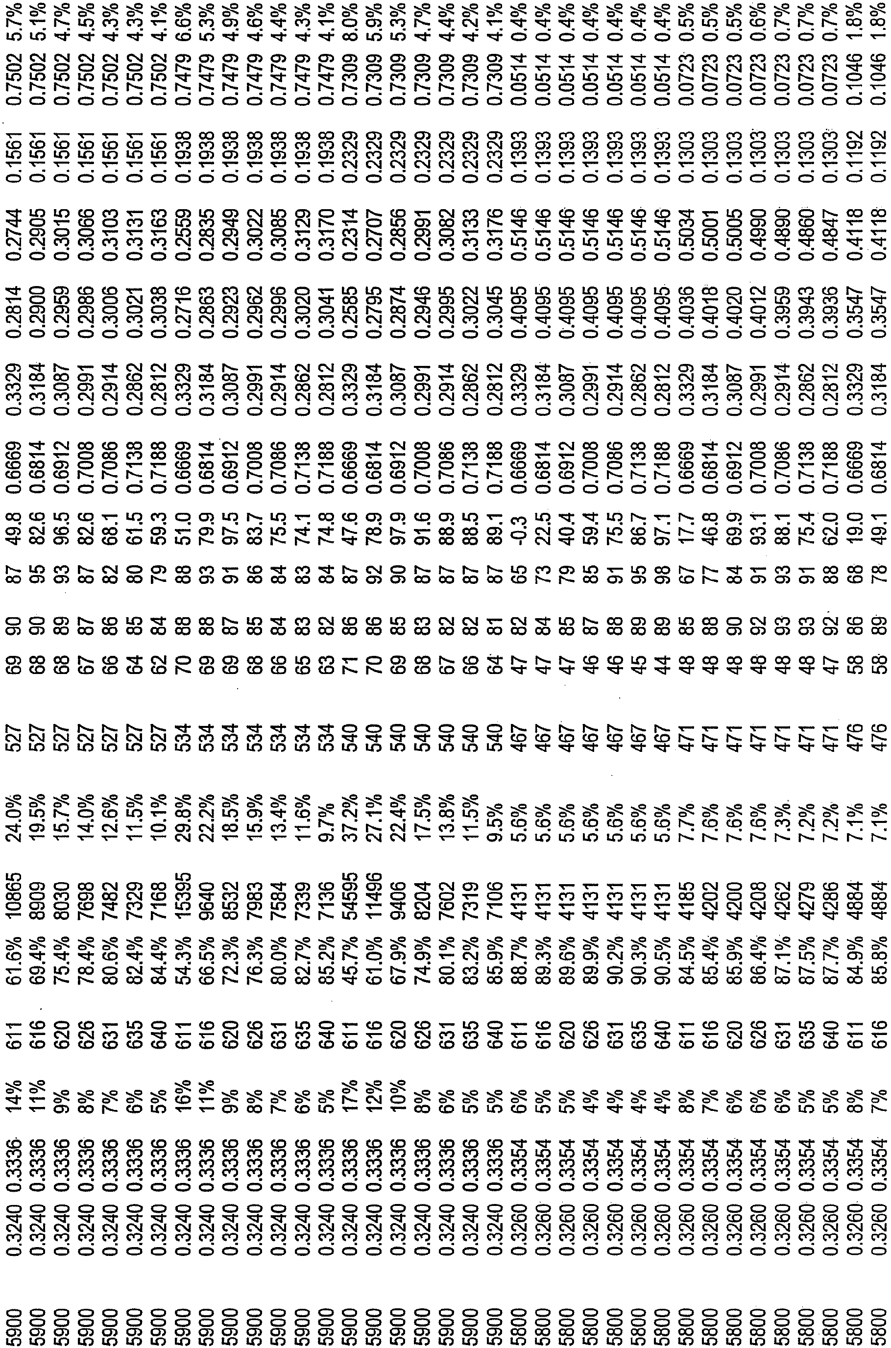


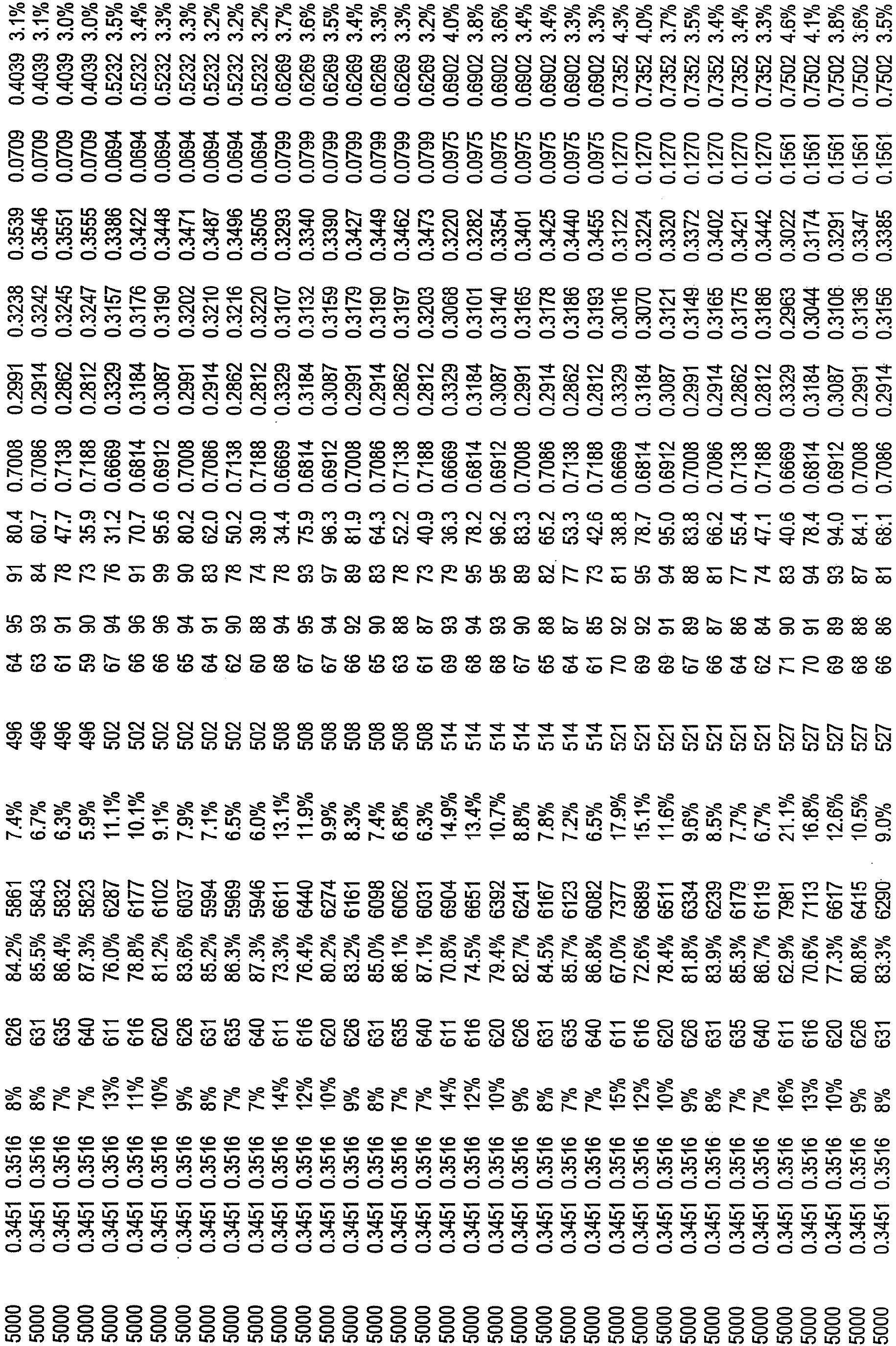


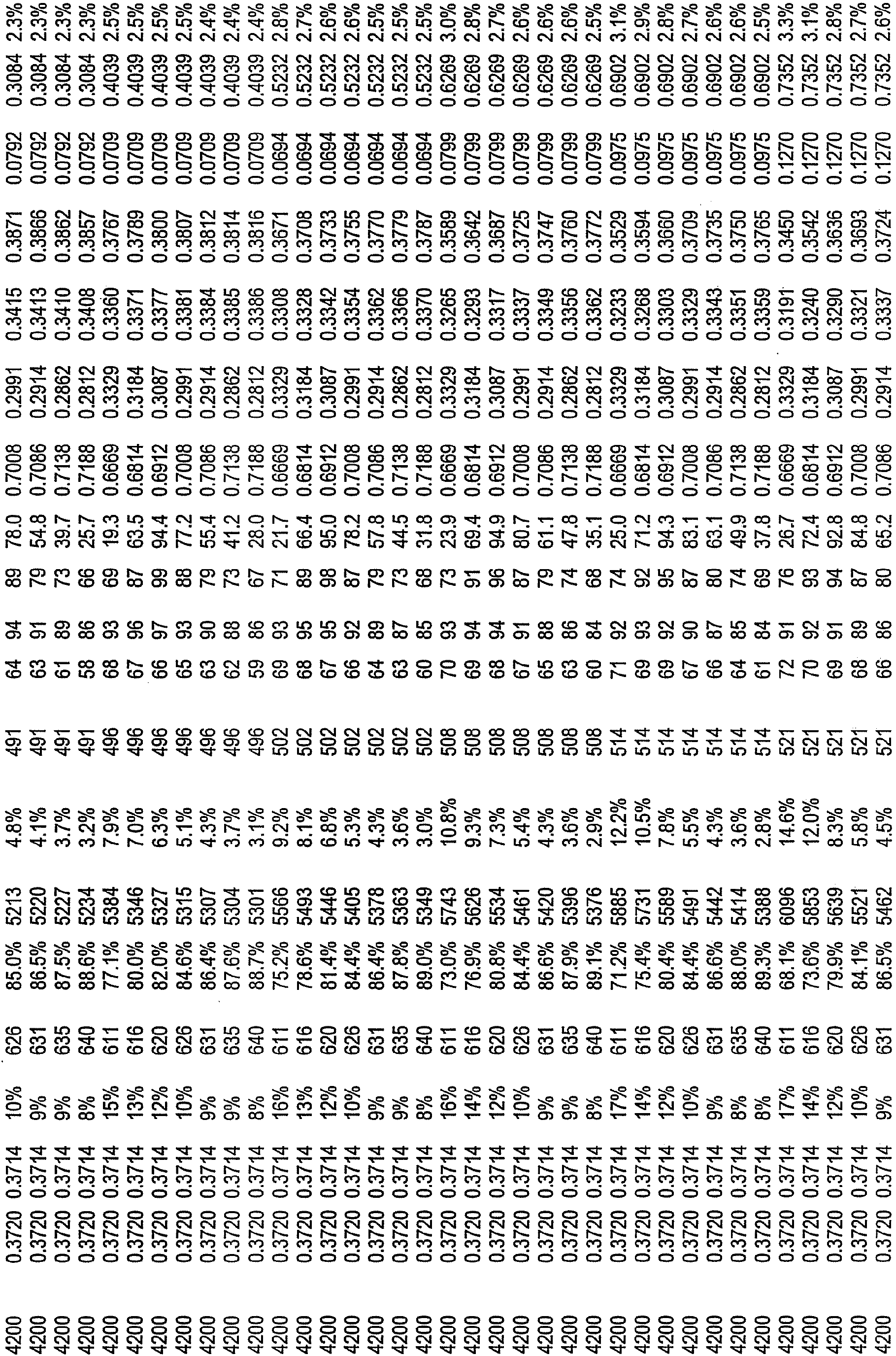


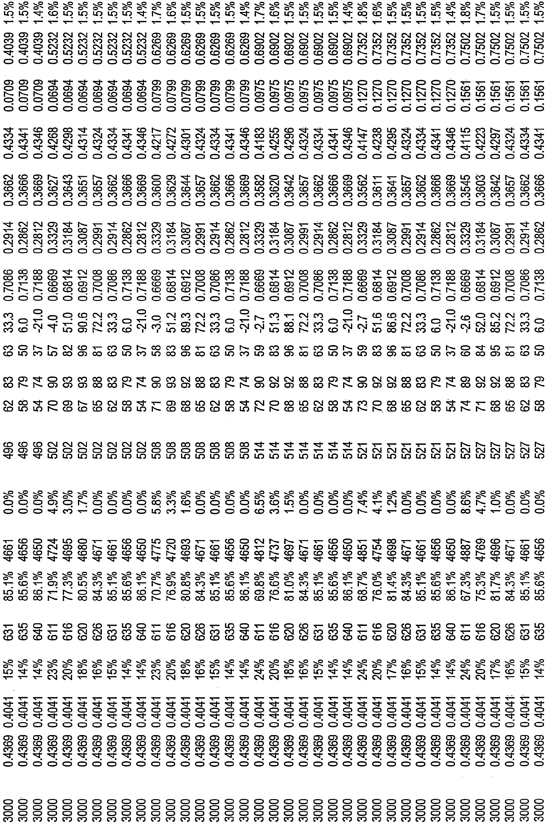


- The following examples are intended to highlight various aspects of the present inventive subject matter and are provided for illustrative purposes only. The following examples should not be used to limit the scope of the present inventive subject matter as defined in the claims.
- Light emitting diodes have been demonstrated to be able to produce white light with efficacy >150L/W and are anticipated to be the predominant lighting devices within the next decade. LED based luminaires are already commercially available with efficacies up to 60L/W. Many systems are based primarily on LEDs which combine blue + YAG:Ce or BOSE, or RGB InGaN / AlInGaP LEDs or UV LED excited RGB phosphors. These methods have good efficacy but only medium CRI. They have not been able to demonstrate both high CRI and high efficacy especially with color temperatures between 2700K and 4000K. The general approach described in
U.S. Patent No. 7,213,940 was utilized to produce white light and demonstrate a warm-white luminaire with a wall plug efficacy of 85 lumens per watt, a CRI Ra of 92 at a CCT of 2865K. By combining high efficiency AlInGaP Red LEDs and wide spectrum yellowish phosphor LEDs, high-efficacy high-CRI warm-white illumination was produced. - A YAG:Ce phosphor was combined with 452nm peak blue InGaN LEDs such that the color point fell well above the black body locus and the color was distinctly yellow. This point coincided with the peak efficacy for the Blue + YAG:Ce system but this was not a white LED lamp.
- Mixing this light with a reddish AlInGaP LED's light, we were able to pull the yellow color back to the black body curve and produce warm white light.
Fig. 4 shows the tie lines between a red LED and various yellow and yellowish points on the Blue/YAG tie line. - With this approach, high efficacy warm white light with an exceptional CRI was produced. The combination of a yellow phosphor LED and a red LED dramatically improved the CRI and efficacy of the light. Initial experiments achieved CRI Ra > 90 for color temperatures below 3500K and very good efficacy.
-
Figure 5 shows the efficacy and high CRI achievable with this initial arrangement. The complete integrated (power supply, optic, etc) LED light unit was tested (report #1859182-1) at The CSA International laboratory (NVLAP certified by NIST) in Atlanta Ga, USA and found to have the following results at thermal equilibrium. 619 lumens, 2865K, 85LPW, CRI Ra 92, 120VAC, 7.28 W, PF = 0.97 (after 90 minutes of operation to achieve thermal equilibrium at an ambient temperature of 25 °C). - In another example, an LR6 from LED Lighting Fixtures of Morrisville, NC was modified to include a BCG LED by replacing one of the more blueish phosphor LEDs with a 480nm dominant BCG LED. The LR6 would typically have a color temperature of 2700K. Adding the BCG LED allowed the LR6 to be tuned to provide a 3500K fixture that is very close to the BBL, with an efficacy of ∼60L/W, and a CRI Ra of 95.
- Any two or more structural parts of the devices described herein can be integrated. Any structural part of the devices described herein can be provided in two or more parts, which are held together, if necessary.
- Furthermore, while certain embodiments of the present inventive subject matter have been illustrated with reference to specific combinations of elements, various other combinations may also be provided without departing from the teachings of the present inventive subject matter. Thus, the present inventive subject matter should not be construed as being limited to the particular exemplary embodiments described herein and illustrated in the Figures, but may also encompass combinations of elements of the various illustrated embodiments.
- Many alterations and modifications may be made by those having ordinary skill in the art, given the benefit of the present disclosure, without departing from the scope of the inventive subject matter. Therefore, it must be understood that the illustrated embodiments have been set forth only for the purposes of example, and that it should not be taken as limiting the inventive subject matter as defined by the following claims.
Claims (11)
- A lighting device comprising:a first group of non-white, non-saturated, phosphor light emitting diode light sources, the first group of non-white light sources comprising at least one light source, when electricity is supplied to the first group of non-white light sources to emit light, the first group of non-white light sources emits light having u', v' color coordinates which define a point which is (1) spaced from the planckian blackbody locus by at least 0.01 u'v' and (2) within an area on a 1976 CIE Chromaticity Diagram enclosed by a first saturated light curve extending along all points representing saturated light having wavelength in the range of from about 430 nm to about 480 nm, a first line segment extending from a point representing saturated light having wavelength of about 480 nm to a point representing saturated light having wavelength of about 560 nm, a second saturated light curve extending along all points representing saturated light having wavelength in the range of from about 560 nm to about 580 nm, and a second line segment extending from a point representing saturated light having wavelength of about 580 nm to a point representing saturated light having wavelength of about 430 nm,the first group of non-white, non-saturated, phosphor light emitting light sources comprising (a) at least a first solid state light emitter which has a peak emission wavelength in the range of from about 405 nm to about 490 nm and at least a first luminescent material which has a dominant emission wavelength in the range of from about 550 nm to about 600 nm, or (b) at least a first solid state light emitter which has a peak emission wavelength in the range of from about 390 nm to about 480 nm and at least a first luminescent material which has a dominant emission wavelength in the range of from about 560 nm to about 580 nm;a first group of supplemental light emitters comprising at least one light emitter, the first group of supplemental light emitters having a dominant emission wavelength in the range of from about 465 nm to about 540 nm; anda second group of supplemental light emitters comprising at least one light emitter, the second group of supplemental light emitters having a dominant emission wavelength in the range of from about 600 nm to about 640 nm,wherein when each of the first group of non-white, non-saturated, phosphor light emitting light sources, each of the first group of supplemental light emitters and each of the second group of supplemental light emitters are emitting light, a mixture of (1) light emitted from the lighting device which was emitted by the first group of non-white light sources, (2) light emitted from the lighting device which was emitted by the first group of supplemental light emitters, and (3) light emitted from the lighting device which was emitted by the second group of supplemental light emitters would, in the absence of any additional light, have a combined illumination having x, y color coordinates which is within 0.01 u'v' of at least one point on the blackbody locus on a 1976 CIE Chromaticity Diagram.
- A lighting device as recited in claim 1, wherein the lighting device comprises:a first string comprising said first group of non-white, non-saturated, phosphor light emitting light sources and said first group of supplemental light emitters;a second string comprising a second group of non-white light sources, the second group of non-white sources comprising at least one light source, when electricity is supplied to the second group of non-white light sources to emit light, the second group of non-white light sources emits light having u', v' color coordinates which define a point which is (1) spaced from the planckian blackbody locus by at least 0.01 u'v' and (2) within an area on a 1976 CIE Chromaticity Diagram enclosed by a first saturated light curve extending along all points representing saturated light having wavelength in the range of from about 430 nm to about 480 nm, a first line segment extending from a point representing saturated light having wavelength of about 480 nm to a point representing saturated light having wavelength of about 560 nm, a second saturated light curve extending along all points representing saturated light having wavelength in the range of from about 560 nm to about 580 nm, and a second line segment extending from a point representing saturated light having wavelength of about 580 nm to a point representing saturated light having wavelength of about 430 nm; anda third string comprising said second group of supplemental light emitters.
- A lighting device as recited in claim 2, wherein when each of the first group of non-white light sources, each of the first group of supplemental light emitters, each of the second group of non-white light sources and each of the second group of supplemental light emitters are emitting light, a mixture of (1) light emitted from the lighting device which was emitted by the first group of non-white light sources, (2) light emitted from the lighting device which was emitted by the first group of supplemental light emitters, (3) light emitted from the lighting device which was emitted by the second group of non-white light sources and (4) light emitted from the lighting device which was emitted by the second group of supplemental light emitters, would, in the absence of any additional light, have a combined illumination having x, y color coordinates which is within 0.01 u'v' of at least one point on the blackbody locus on a 1976 CIE Chromaticity Diagram.
- A lighting device as recited in any one of claims 1-3, wherein the first group of non-white, non-saturated, phosphor light emitting light sources comprises at least a first light source solid state light emitter and at least a first luminescent material.
- A lighting device as recited in any one of claims 1-4, wherein the first group of non-white, non-saturated, phosphor light emitting light sources comprises at least a first light emitting diode.
- A lighting device as recited in any one of claims 1-5, wherein the lighting device further comprises at least a first power line, and when energy is supplied to the first power line, the lighting device emits light which is within 0.01 u'v' of at least one point on the blackbody locus on a 1976 CIE Chromaticity Diagram.
- A lighting device as recited in any one of claims 1-6, wherein when light is emitted from the lighting device, light emitted by the first group of non-white, non-saturated, phosphor light emitting light sources comprises from about 40 percent to about 95 percent of the light emitted from the lighting device.
- A lighting device as recited in any one of claims 1-7, wherein the first group of non-white, non-saturated, phosphor light emitting light sources comprises at least a first light source having a FWHM value of at least 40 nm.
- A lighting device as recited in any one of claims 1-8, wherein when electricity is supplied to each of the non-white light sources to emit light, each of the non-white light sources emits light having u', v' color coordinates which define a point which is (1) spaced from the planckian blackbody locus by at least 0.01 u'v' and (2) within an area on a 1976 CIE Chromaticity Diagram enclosed by a first saturated light curve extending along all points representing saturated light having wavelength in the range of from about 430 nm to about 480 nm, a first line segment extending from a point representing saturated light having wavelength of about 480 nm to a point representing saturated light having wavelength of about 560 nm, a second saturated light curve extending along all points representing saturated light having wavelength in the range of from about 560 nm to about 580 nm, and a second line segment extending from a point representing saturated light having wavelength of about 580 nm to a point representing saturated light having wavelength of about 430 nm.
- A lighting device as recited in any one of claims 1-9, wherein each of the first group of supplemental light emitters has a dominant emission wavelength in the range of from about 465 nm to about 540 nm.
- A lighting device as recited in any one of claims 1-10, wherein each of the second group of supplemental light emitters has a dominant emission wavelength in the range of from about 600 nm to about 640 nm.
Applications Claiming Priority (3)
| Application Number | Priority Date | Filing Date | Title |
|---|---|---|---|
| US97888007P | 2007-10-10 | 2007-10-10 | |
| US3736508P | 2008-03-18 | 2008-03-18 | |
| PCT/US2008/079299 WO2009049019A1 (en) | 2007-10-10 | 2008-10-09 | Lighting device and method of making |
Publications (2)
| Publication Number | Publication Date |
|---|---|
| EP2210036A1 EP2210036A1 (en) | 2010-07-28 |
| EP2210036B1 true EP2210036B1 (en) | 2016-11-23 |
Family
ID=40130584
Family Applications (1)
| Application Number | Title | Priority Date | Filing Date |
|---|---|---|---|
| EP08837037.4A Active EP2210036B1 (en) | 2007-10-10 | 2008-10-09 | Lighting device and method of making |
Country Status (8)
| Country | Link |
|---|---|
| US (1) | US8018135B2 (en) |
| EP (1) | EP2210036B1 (en) |
| JP (1) | JP2011501417A (en) |
| KR (1) | KR101722265B1 (en) |
| CN (1) | CN101821544B (en) |
| BR (1) | BRPI0818048B1 (en) |
| TW (1) | TWI481068B (en) |
| WO (1) | WO2009049019A1 (en) |
Families Citing this family (279)
| Publication number | Priority date | Publication date | Assignee | Title |
|---|---|---|---|---|
| US20060097385A1 (en) | 2004-10-25 | 2006-05-11 | Negley Gerald H | Solid metal block semiconductor light emitting device mounting substrates and packages including cavities and heat sinks, and methods of packaging same |
| US8125137B2 (en) | 2005-01-10 | 2012-02-28 | Cree, Inc. | Multi-chip light emitting device lamps for providing high-CRI warm white light and light fixtures including the same |
| US7564180B2 (en) | 2005-01-10 | 2009-07-21 | Cree, Inc. | Light emission device and method utilizing multiple emitters and multiple phosphors |
| US7758223B2 (en) * | 2005-04-08 | 2010-07-20 | Toshiba Lighting & Technology Corporation | Lamp having outer shell to radiate heat of light source |
| JP5249773B2 (en) * | 2005-11-18 | 2013-07-31 | クリー インコーポレイテッド | Solid state lighting panel with variable voltage boost current source |
| US8123375B2 (en) * | 2005-11-18 | 2012-02-28 | Cree, Inc. | Tile for solid state lighting |
| US8514210B2 (en) | 2005-11-18 | 2013-08-20 | Cree, Inc. | Systems and methods for calibrating solid state lighting panels using combined light output measurements |
| WO2007075815A2 (en) | 2005-12-21 | 2007-07-05 | Cree Led Lighting Solutions, Inc. | Lighting device and lighting method |
| US8441179B2 (en) | 2006-01-20 | 2013-05-14 | Cree, Inc. | Lighting devices having remote lumiphors that are excited by lumiphor-converted semiconductor excitation sources |
| US9921428B2 (en) | 2006-04-18 | 2018-03-20 | Cree, Inc. | Light devices, display devices, backlighting devices, edge-lighting devices, combination backlighting and edge-lighting devices |
| JP5053363B2 (en) | 2006-04-18 | 2012-10-17 | クリー インコーポレイテッド | Lighting device and lighting method |
| US8998444B2 (en) * | 2006-04-18 | 2015-04-07 | Cree, Inc. | Solid state lighting devices including light mixtures |
| US7821194B2 (en) * | 2006-04-18 | 2010-10-26 | Cree, Inc. | Solid state lighting devices including light mixtures |
| US7766508B2 (en) * | 2006-09-12 | 2010-08-03 | Cree, Inc. | LED lighting fixture |
| US7665862B2 (en) * | 2006-09-12 | 2010-02-23 | Cree, Inc. | LED lighting fixture |
| US8029155B2 (en) | 2006-11-07 | 2011-10-04 | Cree, Inc. | Lighting device and lighting method |
| US9441793B2 (en) | 2006-12-01 | 2016-09-13 | Cree, Inc. | High efficiency lighting device including one or more solid state light emitters, and method of lighting |
| US7824070B2 (en) | 2007-03-22 | 2010-11-02 | Cree, Inc. | LED lighting fixture |
| EP2469152B1 (en) | 2007-05-08 | 2018-11-28 | Cree, Inc. | Lighting devices and methods for lighting |
| WO2008137977A1 (en) | 2007-05-08 | 2008-11-13 | Cree Led Lighting Solutions, Inc. | Lighting device and lighting method |
| WO2009014219A1 (en) * | 2007-07-26 | 2009-01-29 | Panasonic Electric Works Co., Ltd. | Led illumination device |
| JP4569683B2 (en) | 2007-10-16 | 2010-10-27 | 東芝ライテック株式会社 | Light emitting element lamp and lighting apparatus |
| US8058088B2 (en) | 2008-01-15 | 2011-11-15 | Cree, Inc. | Phosphor coating systems and methods for light emitting structures and packaged light emitting diodes including phosphor coating |
| US10008637B2 (en) | 2011-12-06 | 2018-06-26 | Cree, Inc. | Light emitter devices and methods with reduced dimensions and improved light output |
| US8350461B2 (en) | 2008-03-28 | 2013-01-08 | Cree, Inc. | Apparatus and methods for combining light emitters |
| CA2719249C (en) * | 2008-06-27 | 2013-04-16 | Toshiba Lighting & Technology Corporation | Light-emitting element lamp and lighting equipment |
| US8674913B2 (en) | 2008-09-05 | 2014-03-18 | Ketra, Inc. | LED transceiver front end circuitry and related methods |
| US8773336B2 (en) | 2008-09-05 | 2014-07-08 | Ketra, Inc. | Illumination devices and related systems and methods |
| US10210750B2 (en) | 2011-09-13 | 2019-02-19 | Lutron Electronics Co., Inc. | System and method of extending the communication range in a visible light communication system |
| US8521035B2 (en) | 2008-09-05 | 2013-08-27 | Ketra, Inc. | Systems and methods for visible light communication |
| US8471496B2 (en) * | 2008-09-05 | 2013-06-25 | Ketra, Inc. | LED calibration systems and related methods |
| WO2010027459A2 (en) | 2008-09-05 | 2010-03-11 | Firefly Green Technologies Inc. | Optical communication device, method and system |
| US9509525B2 (en) | 2008-09-05 | 2016-11-29 | Ketra, Inc. | Intelligent illumination device |
| US8456092B2 (en) * | 2008-09-05 | 2013-06-04 | Ketra, Inc. | Broad spectrum light source calibration systems and related methods |
| US9276766B2 (en) | 2008-09-05 | 2016-03-01 | Ketra, Inc. | Display calibration systems and related methods |
| US8858032B2 (en) * | 2008-10-24 | 2014-10-14 | Cree, Inc. | Lighting device, heat transfer structure and heat transfer element |
| US8220971B2 (en) * | 2008-11-21 | 2012-07-17 | Xicato, Inc. | Light emitting diode module with three part color matching |
| US7967652B2 (en) | 2009-02-19 | 2011-06-28 | Cree, Inc. | Methods for combining light emitting devices in a package and packages including combined light emitting devices |
| US8339029B2 (en) | 2009-02-19 | 2012-12-25 | Cree, Inc. | Light emitting devices and systems having tunable chromaticity |
| US8333631B2 (en) * | 2009-02-19 | 2012-12-18 | Cree, Inc. | Methods for combining light emitting devices in a package and packages including combined light emitting devices |
| JP5333758B2 (en) * | 2009-02-27 | 2013-11-06 | 東芝ライテック株式会社 | Lighting device and lighting fixture |
| GB2469794B (en) * | 2009-04-24 | 2014-02-19 | Photonstar Led Ltd | High colour quality luminaire |
| JP5515931B2 (en) * | 2009-04-24 | 2014-06-11 | 東芝ライテック株式会社 | Light emitting device and lighting device |
| GB2500837B (en) * | 2009-04-24 | 2014-05-07 | Photonstar Led Ltd | High colour quality luminaire |
| US8926139B2 (en) * | 2009-05-01 | 2015-01-06 | Express Imaging Systems, Llc | Gas-discharge lamp replacement with passive cooling |
| US8237633B2 (en) * | 2009-05-12 | 2012-08-07 | Global Oled Technology Llc | Electro-luminescent display with adjustable white point |
| US8337030B2 (en) * | 2009-05-13 | 2012-12-25 | Cree, Inc. | Solid state lighting devices having remote luminescent material-containing element, and lighting methods |
| JP5354191B2 (en) * | 2009-06-30 | 2013-11-27 | 東芝ライテック株式会社 | Light bulb shaped lamp and lighting equipment |
| JP5348410B2 (en) * | 2009-06-30 | 2013-11-20 | 東芝ライテック株式会社 | Lamp with lamp and lighting equipment |
| US20110026264A1 (en) * | 2009-07-29 | 2011-02-03 | Reed William G | Electrically isolated heat sink for solid-state light |
| JP2011049527A (en) * | 2009-07-29 | 2011-03-10 | Toshiba Lighting & Technology Corp | Led lighting equipment |
| US8648546B2 (en) | 2009-08-14 | 2014-02-11 | Cree, Inc. | High efficiency lighting device including one or more saturated light emitters, and method of lighting |
| US9713211B2 (en) | 2009-09-24 | 2017-07-18 | Cree, Inc. | Solid state lighting apparatus with controllable bypass circuits and methods of operation thereof |
| JP2011071242A (en) * | 2009-09-24 | 2011-04-07 | Toshiba Lighting & Technology Corp | Light emitting device and illuminating device |
| US10264637B2 (en) * | 2009-09-24 | 2019-04-16 | Cree, Inc. | Solid state lighting apparatus with compensation bypass circuits and methods of operation thereof |
| US8901845B2 (en) | 2009-09-24 | 2014-12-02 | Cree, Inc. | Temperature responsive control for lighting apparatus including light emitting devices providing different chromaticities and related methods |
| US8777449B2 (en) | 2009-09-25 | 2014-07-15 | Cree, Inc. | Lighting devices comprising solid state light emitters |
| US8324789B2 (en) * | 2009-09-25 | 2012-12-04 | Toshiba Lighting & Technology Corporation | Self-ballasted lamp and lighting equipment |
| US9068719B2 (en) | 2009-09-25 | 2015-06-30 | Cree, Inc. | Light engines for lighting devices |
| CN102032481B (en) * | 2009-09-25 | 2014-01-08 | 东芝照明技术株式会社 | Lamp with base and lighting equipment |
| JP2011091033A (en) * | 2009-09-25 | 2011-05-06 | Toshiba Lighting & Technology Corp | Light-emitting module, bulb-shaped lamp and lighting equipment |
| US9285103B2 (en) | 2009-09-25 | 2016-03-15 | Cree, Inc. | Light engines for lighting devices |
| CN102032480B (en) * | 2009-09-25 | 2013-07-31 | 东芝照明技术株式会社 | Self-ballasted lamp and lighting equipment |
| US8602579B2 (en) | 2009-09-25 | 2013-12-10 | Cree, Inc. | Lighting devices including thermally conductive housings and related structures |
| KR20120094477A (en) | 2009-09-25 | 2012-08-24 | 크리, 인코포레이티드 | Lighting device with low glare and high light level uniformity |
| US9030120B2 (en) | 2009-10-20 | 2015-05-12 | Cree, Inc. | Heat sinks and lamp incorporating same |
| US9217542B2 (en) | 2009-10-20 | 2015-12-22 | Cree, Inc. | Heat sinks and lamp incorporating same |
| US9435493B2 (en) | 2009-10-27 | 2016-09-06 | Cree, Inc. | Hybrid reflector system for lighting device |
| US8779685B2 (en) * | 2009-11-19 | 2014-07-15 | Intematix Corporation | High CRI white light emitting devices and drive circuitry |
| US20130038798A1 (en) * | 2009-12-16 | 2013-02-14 | Sharp Kabushiki Kaisha | Display device and television receiver |
| US8508116B2 (en) | 2010-01-27 | 2013-08-13 | Cree, Inc. | Lighting device with multi-chip light emitters, solid state light emitter support members and lighting elements |
| WO2011100224A2 (en) | 2010-02-12 | 2011-08-18 | Cree, Inc. | Lighting devices that comprise one or more solid state light emitters |
| US8773007B2 (en) | 2010-02-12 | 2014-07-08 | Cree, Inc. | Lighting devices that comprise one or more solid state light emitters |
| CN102844619B (en) | 2010-02-12 | 2016-12-28 | 科锐公司 | There is the luminaire of radiating piece |
| CN102782391B (en) | 2010-02-12 | 2016-08-03 | 科锐公司 | Solid state illumination device and assembly method thereof |
| US9518715B2 (en) * | 2010-02-12 | 2016-12-13 | Cree, Inc. | Lighting devices that comprise one or more solid state light emitters |
| JP5257622B2 (en) * | 2010-02-26 | 2013-08-07 | 東芝ライテック株式会社 | Light bulb shaped lamp and lighting equipment |
| US9052067B2 (en) | 2010-12-22 | 2015-06-09 | Cree, Inc. | LED lamp with high color rendering index |
| US8508127B2 (en) * | 2010-03-09 | 2013-08-13 | Cree, Inc. | High CRI lighting device with added long-wavelength blue color |
| US8643038B2 (en) * | 2010-03-09 | 2014-02-04 | Cree, Inc. | Warm white LEDs having high color rendering index values and related luminophoric mediums |
| US20110220920A1 (en) * | 2010-03-09 | 2011-09-15 | Brian Thomas Collins | Methods of forming warm white light emitting devices having high color rendering index values and related light emitting devices |
| EP2365525A3 (en) * | 2010-03-12 | 2013-05-29 | Toshiba Lighting & Technology Corporation | Illumination apparatus having an array of red and phosphour coated blue LEDs |
| US8476836B2 (en) | 2010-05-07 | 2013-07-02 | Cree, Inc. | AC driven solid state lighting apparatus with LED string including switched segments |
| WO2011143197A2 (en) * | 2010-05-13 | 2011-11-17 | Cree, Inc. | Lighting device and method of making |
| US8684559B2 (en) | 2010-06-04 | 2014-04-01 | Cree, Inc. | Solid state light source emitting warm light with high CRI |
| WO2011163334A1 (en) | 2010-06-22 | 2011-12-29 | Express Imaging Systems, Llc | Solid state lighting device and method employing heat exchanger thermally coupled circuit board |
| US20120155076A1 (en) * | 2010-06-24 | 2012-06-21 | Intematix Corporation | Led-based light emitting systems and devices |
| US9173261B2 (en) | 2010-07-30 | 2015-10-27 | Wesley L. Mokry | Secondary-side alternating energy transfer control with inverted reference and LED-derived power supply |
| US8946998B2 (en) | 2010-08-09 | 2015-02-03 | Intematix Corporation | LED-based light emitting systems and devices with color compensation |
| US9386668B2 (en) | 2010-09-30 | 2016-07-05 | Ketra, Inc. | Lighting control system |
| USRE49454E1 (en) | 2010-09-30 | 2023-03-07 | Lutron Technology Company Llc | Lighting control system |
| US8569974B2 (en) | 2010-11-01 | 2013-10-29 | Cree, Inc. | Systems and methods for controlling solid state lighting devices and lighting apparatus incorporating such systems and/or methods |
| US9648673B2 (en) | 2010-11-05 | 2017-05-09 | Cree, Inc. | Lighting device with spatially segregated primary and secondary emitters |
| US10267506B2 (en) | 2010-11-22 | 2019-04-23 | Cree, Inc. | Solid state lighting apparatuses with non-uniformly spaced emitters for improved heat distribution, system having the same, and methods having the same |
| US8556469B2 (en) | 2010-12-06 | 2013-10-15 | Cree, Inc. | High efficiency total internal reflection optic for solid state lighting luminaires |
| US11101408B2 (en) | 2011-02-07 | 2021-08-24 | Creeled, Inc. | Components and methods for light emitting diode (LED) lighting |
| US10522518B2 (en) * | 2010-12-23 | 2019-12-31 | Bench Walk Lighting, LLC | Light source with tunable CRI |
| TWI421449B (en) * | 2011-02-01 | 2014-01-01 | Lite On Electronics Guangzhou | Lighting device and method for selecting color of toner in medium layer thereof |
| US10178723B2 (en) * | 2011-06-03 | 2019-01-08 | Cree, Inc. | Systems and methods for controlling solid state lighting devices and lighting apparatus incorporating such systems and/or methods |
| US10098197B2 (en) | 2011-06-03 | 2018-10-09 | Cree, Inc. | Lighting devices with individually compensating multi-color clusters |
| US8796952B2 (en) * | 2011-03-03 | 2014-08-05 | Cree, Inc. | Semiconductor light emitting devices having selectable and/or adjustable color points and related methods |
| US8791642B2 (en) | 2011-03-03 | 2014-07-29 | Cree, Inc. | Semiconductor light emitting devices having selectable and/or adjustable color points and related methods |
| US8823289B2 (en) * | 2011-03-24 | 2014-09-02 | Cirrus Logic, Inc. | Color coordination of electronic light sources with dimming and temperature responsiveness |
| JP5941134B2 (en) | 2011-04-01 | 2016-06-29 | クリー インコーポレイテッドCree Inc. | Lighting module |
| CN102748595B (en) * | 2011-04-19 | 2015-03-11 | 展晶科技(深圳)有限公司 | Light emitting diode (LED) light source device |
| US8921875B2 (en) | 2011-05-10 | 2014-12-30 | Cree, Inc. | Recipient luminophoric mediums having narrow spectrum luminescent materials and related semiconductor light emitting devices and methods |
| US8814621B2 (en) | 2011-06-03 | 2014-08-26 | Cree, Inc. | Methods of determining and making red nitride compositions |
| US8729790B2 (en) | 2011-06-03 | 2014-05-20 | Cree, Inc. | Coated phosphors and light emitting devices including the same |
| US8906263B2 (en) | 2011-06-03 | 2014-12-09 | Cree, Inc. | Red nitride phosphors |
| US9839083B2 (en) | 2011-06-03 | 2017-12-05 | Cree, Inc. | Solid state lighting apparatus and circuits including LED segments configured for targeted spectral power distribution and methods of operating the same |
| US8747697B2 (en) | 2011-06-07 | 2014-06-10 | Cree, Inc. | Gallium-substituted yttrium aluminum garnet phosphor and light emitting devices including the same |
| US20120320568A1 (en) * | 2011-06-17 | 2012-12-20 | General Scientific Corporation | Medical/dental headlight system with improved color rendition |
| US9642208B2 (en) | 2011-06-28 | 2017-05-02 | Cree, Inc. | Variable correlated color temperature luminary constructs |
| US8684569B2 (en) | 2011-07-06 | 2014-04-01 | Cree, Inc. | Lens and trim attachment structure for solid state downlights |
| US8749172B2 (en) | 2011-07-08 | 2014-06-10 | Ketra, Inc. | Luminance control for illumination devices |
| US10490712B2 (en) | 2011-07-21 | 2019-11-26 | Cree, Inc. | Light emitter device packages, components, and methods for improved chemical resistance and related methods |
| US10211380B2 (en) | 2011-07-21 | 2019-02-19 | Cree, Inc. | Light emitting devices and components having improved chemical resistance and related methods |
| US10686107B2 (en) | 2011-07-21 | 2020-06-16 | Cree, Inc. | Light emitter devices and components with improved chemical resistance and related methods |
| US9510413B2 (en) | 2011-07-28 | 2016-11-29 | Cree, Inc. | Solid state lighting apparatus and methods of forming |
| US8742671B2 (en) | 2011-07-28 | 2014-06-03 | Cree, Inc. | Solid state lighting apparatus and methods using integrated driver circuitry |
| WO2013036070A2 (en) * | 2011-09-08 | 2013-03-14 | Lg Innotek Co., Ltd. | Lighting device and lighting control method |
| US8791641B2 (en) | 2011-09-16 | 2014-07-29 | Cree, Inc. | Solid-state lighting apparatus and methods using energy storage |
| US20130081610A1 (en) * | 2011-09-29 | 2013-04-04 | Osram Opto Semiconductors Gmbh | Oven Lighting |
| CN103062641B (en) * | 2011-10-20 | 2016-10-19 | 欧司朗股份有限公司 | Light source cell, the illuminator being furnished with this light source cell and armarium |
| WO2013061943A1 (en) * | 2011-10-24 | 2013-05-02 | 株式会社東芝 | White light source and white light source system using white light source |
| US8919975B2 (en) | 2011-11-09 | 2014-12-30 | Cree, Inc. | Lighting device providing improved color rendering |
| US8884508B2 (en) | 2011-11-09 | 2014-11-11 | Cree, Inc. | Solid state lighting device including multiple wavelength conversion materials |
| WO2013071181A2 (en) | 2011-11-11 | 2013-05-16 | Cirrus Logic, Inc. | Color mixing of electronic light sources with correlation between phase-cut dimmer angle and predetermined black body radiation function |
| US8736186B2 (en) | 2011-11-14 | 2014-05-27 | Cree, Inc. | Solid state lighting switches and fixtures providing selectively linked dimming and color control and methods of operating |
| US10043960B2 (en) | 2011-11-15 | 2018-08-07 | Cree, Inc. | Light emitting diode (LED) packages and related methods |
| US9496466B2 (en) | 2011-12-06 | 2016-11-15 | Cree, Inc. | Light emitter devices and methods, utilizing light emitting diodes (LEDs), for improved light extraction |
| US8847516B2 (en) | 2011-12-12 | 2014-09-30 | Cree, Inc. | Lighting devices including current shunting responsive to LED nodes and related methods |
| US8823285B2 (en) | 2011-12-12 | 2014-09-02 | Cree, Inc. | Lighting devices including boost converters to control chromaticity and/or brightness and related methods |
| US10187942B2 (en) | 2011-12-23 | 2019-01-22 | Cree, Inc. | Methods and circuits for controlling lighting characteristics of solid state lighting devices and lighting apparatus incorporating such methods and/or circuits |
| US9335531B2 (en) | 2011-12-30 | 2016-05-10 | Cree, Inc. | LED lighting using spectral notching |
| US9318669B2 (en) | 2012-01-30 | 2016-04-19 | Cree, Inc. | Methods of determining and making red nitride compositions |
| US9806246B2 (en) | 2012-02-07 | 2017-10-31 | Cree, Inc. | Ceramic-based light emitting diode (LED) devices, components, and methods |
| US9786825B2 (en) | 2012-02-07 | 2017-10-10 | Cree, Inc. | Ceramic-based light emitting diode (LED) devices, components, and methods |
| US9343441B2 (en) | 2012-02-13 | 2016-05-17 | Cree, Inc. | Light emitter devices having improved light output and related methods |
| US9240530B2 (en) | 2012-02-13 | 2016-01-19 | Cree, Inc. | Light emitter devices having improved chemical and physical resistance and related methods |
| US9735198B2 (en) | 2012-03-30 | 2017-08-15 | Cree, Inc. | Substrate based light emitter devices, components, and related methods |
| US9538590B2 (en) | 2012-03-30 | 2017-01-03 | Cree, Inc. | Solid state lighting apparatuses, systems, and related methods |
| CN103378078B (en) * | 2012-04-17 | 2017-04-05 | 台达电子工业股份有限公司 | Illuminator and the method for producing white light |
| US9572226B2 (en) | 2012-07-01 | 2017-02-14 | Cree, Inc. | Master/slave arrangement for lighting fixture modules |
| US9980350B2 (en) | 2012-07-01 | 2018-05-22 | Cree, Inc. | Removable module for a lighting fixture |
| US9717125B2 (en) | 2012-07-01 | 2017-07-25 | Cree, Inc. | Enhanced lighting fixture |
| US10721808B2 (en) | 2012-07-01 | 2020-07-21 | Ideal Industries Lighting Llc | Light fixture control |
| US9872367B2 (en) | 2012-07-01 | 2018-01-16 | Cree, Inc. | Handheld device for grouping a plurality of lighting fixtures |
| US9204503B1 (en) | 2012-07-03 | 2015-12-01 | Philips International, B.V. | Systems and methods for dimming multiple lighting devices by alternating transfer from a magnetic storage element |
| JP6087116B2 (en) * | 2012-11-26 | 2017-03-01 | シチズン電子株式会社 | LED light emitting unit and LED light emitting device |
| US20140160774A1 (en) * | 2012-12-06 | 2014-06-12 | Goodrich Lighting Systems, Inc. | Color mixing aviation anti-collision light |
| US8829821B2 (en) | 2012-12-18 | 2014-09-09 | Cree, Inc. | Auto commissioning lighting fixture |
| US9913348B2 (en) | 2012-12-19 | 2018-03-06 | Cree, Inc. | Light fixtures, systems for controlling light fixtures, and methods of controlling fixtures and methods of controlling lighting control systems |
| US9437788B2 (en) | 2012-12-19 | 2016-09-06 | Cree, Inc. | Light emitting diode (LED) component comprising a phosphor with improved excitation properties |
| US10231300B2 (en) | 2013-01-15 | 2019-03-12 | Cree, Inc. | Systems and methods for controlling solid state lighting during dimming and lighting apparatus incorporating such systems and/or methods |
| US10264638B2 (en) | 2013-01-15 | 2019-04-16 | Cree, Inc. | Circuits and methods for controlling solid state lighting |
| US9316382B2 (en) | 2013-01-31 | 2016-04-19 | Cree, Inc. | Connector devices, systems, and related methods for connecting light emitting diode (LED) modules |
| US9030103B2 (en) | 2013-02-08 | 2015-05-12 | Cree, Inc. | Solid state light emitting devices including adjustable scotopic / photopic ratio |
| US9039746B2 (en) | 2013-02-08 | 2015-05-26 | Cree, Inc. | Solid state light emitting devices including adjustable melatonin suppression effects |
| US9565782B2 (en) | 2013-02-15 | 2017-02-07 | Ecosense Lighting Inc. | Field replaceable power supply cartridge |
| WO2014136748A1 (en) * | 2013-03-04 | 2014-09-12 | 三菱化学株式会社 | Light-emitting device, method for designing light-emitting device, method for driving light-emitting device, illumination method, and method for manufacturing light-emitting device |
| US9185754B2 (en) * | 2013-03-26 | 2015-11-10 | General Led, Inc. | Interconnectable LED module for use in a direct current circuit |
| US9219202B2 (en) | 2013-04-19 | 2015-12-22 | Cree, Inc. | Semiconductor light emitting devices including red phosphors that exhibit good color rendering properties and related red phosphors |
| CN104157261B (en) * | 2013-05-13 | 2017-04-12 | 华硕电脑股份有限公司 | Display mode adjusting method of display device and display mode adjusting module thereof |
| US9360174B2 (en) | 2013-12-05 | 2016-06-07 | Ketra, Inc. | Linear LED illumination device with improved color mixing |
| US9769899B2 (en) | 2014-06-25 | 2017-09-19 | Ketra, Inc. | Illumination device and age compensation method |
| US9247605B1 (en) | 2013-08-20 | 2016-01-26 | Ketra, Inc. | Interference-resistant compensation for illumination devices |
| US9155155B1 (en) | 2013-08-20 | 2015-10-06 | Ketra, Inc. | Overlapping measurement sequences for interference-resistant compensation in light emitting diode devices |
| USRE48955E1 (en) | 2013-08-20 | 2022-03-01 | Lutron Technology Company Llc | Interference-resistant compensation for illumination devices having multiple emitter modules |
| US9332598B1 (en) | 2013-08-20 | 2016-05-03 | Ketra, Inc. | Interference-resistant compensation for illumination devices having multiple emitter modules |
| US9237620B1 (en) | 2013-08-20 | 2016-01-12 | Ketra, Inc. | Illumination device and temperature compensation method |
| US9651632B1 (en) | 2013-08-20 | 2017-05-16 | Ketra, Inc. | Illumination device and temperature calibration method |
| US9345097B1 (en) | 2013-08-20 | 2016-05-17 | Ketra, Inc. | Interference-resistant compensation for illumination devices using multiple series of measurement intervals |
| USRE48956E1 (en) | 2013-08-20 | 2022-03-01 | Lutron Technology Company Llc | Interference-resistant compensation for illumination devices using multiple series of measurement intervals |
| US9578724B1 (en) | 2013-08-20 | 2017-02-21 | Ketra, Inc. | Illumination device and method for avoiding flicker |
| US10074781B2 (en) | 2013-08-29 | 2018-09-11 | Cree, Inc. | Semiconductor light emitting devices including multiple red phosphors that exhibit good color rendering properties with increased brightness |
| US9410664B2 (en) * | 2013-08-29 | 2016-08-09 | Soraa, Inc. | Circadian friendly LED light source |
| US9030127B2 (en) * | 2013-09-20 | 2015-05-12 | Osram Sylvania Inc. | Controlling object appearance with variable spectral distribution of lighting having constant chromaticity |
| US9240528B2 (en) | 2013-10-03 | 2016-01-19 | Cree, Inc. | Solid state lighting apparatus with high scotopic/photopic (S/P) ratio |
| US9736895B1 (en) | 2013-10-03 | 2017-08-15 | Ketra, Inc. | Color mixing optics for LED illumination device |
| US9212809B2 (en) * | 2013-11-21 | 2015-12-15 | Ford Global Technologies, Llc | Photoluminescent dynamic lighting |
| US9146028B2 (en) | 2013-12-05 | 2015-09-29 | Ketra, Inc. | Linear LED illumination device with improved rotational hinge |
| US10154569B2 (en) | 2014-01-06 | 2018-12-11 | Cree, Inc. | Power over ethernet lighting fixture |
| US9593812B2 (en) | 2014-04-23 | 2017-03-14 | Cree, Inc. | High CRI solid state lighting devices with enhanced vividness |
| US9685101B2 (en) | 2014-04-23 | 2017-06-20 | Cree, Inc. | Solid state light-emitting devices with improved contrast |
| US9960322B2 (en) | 2014-04-23 | 2018-05-01 | Cree, Inc. | Solid state lighting devices incorporating notch filtering materials |
| US9241384B2 (en) | 2014-04-23 | 2016-01-19 | Cree, Inc. | Solid state lighting devices with adjustable color point |
| US9215761B2 (en) | 2014-05-15 | 2015-12-15 | Cree, Inc. | Solid state lighting devices with color point non-coincident with blackbody locus |
| US9549448B2 (en) | 2014-05-30 | 2017-01-17 | Cree, Inc. | Wall controller controlling CCT |
| US10278250B2 (en) * | 2014-05-30 | 2019-04-30 | Cree, Inc. | Lighting fixture providing variable CCT |
| US9515056B2 (en) | 2014-06-06 | 2016-12-06 | Cree, Inc. | Solid state lighting device including narrow spectrum emitter |
| US9192013B1 (en) | 2014-06-06 | 2015-11-17 | Cree, Inc. | Lighting devices with variable gamut |
| US9736903B2 (en) | 2014-06-25 | 2017-08-15 | Ketra, Inc. | Illumination device and method for calibrating and controlling an illumination device comprising a phosphor converted LED |
| US10161786B2 (en) | 2014-06-25 | 2018-12-25 | Lutron Ketra, Llc | Emitter module for an LED illumination device |
| US9557214B2 (en) | 2014-06-25 | 2017-01-31 | Ketra, Inc. | Illumination device and method for calibrating an illumination device over changes in temperature, drive current, and time |
| US9392663B2 (en) | 2014-06-25 | 2016-07-12 | Ketra, Inc. | Illumination device and method for controlling an illumination device over changes in drive current and temperature |
| US9961770B2 (en) | 2014-07-22 | 2018-05-01 | Cree, Inc. | Solder pads, methods, and systems for circuitry components |
| US9534741B2 (en) | 2014-07-23 | 2017-01-03 | Cree, Inc. | Lighting devices with illumination regions having different gamut properties |
| JP6463355B2 (en) * | 2014-08-22 | 2019-01-30 | タオライト カンパニー リミテッド | LED lighting apparatus and method |
| US9510416B2 (en) | 2014-08-28 | 2016-11-29 | Ketra, Inc. | LED illumination device and method for accurately controlling the intensity and color point of the illumination device over time |
| US9392660B2 (en) | 2014-08-28 | 2016-07-12 | Ketra, Inc. | LED illumination device and calibration method for accurately characterizing the emission LEDs and photodetector(s) included within the LED illumination device |
| US9572230B2 (en) | 2014-09-30 | 2017-02-14 | Express Imaging Systems, Llc | Centralized control of area lighting hours of illumination |
| CN105526541B (en) * | 2014-10-20 | 2019-08-20 | 福特全球技术公司 | Luminescence generated by light dynamic lighting |
| US9445485B2 (en) | 2014-10-24 | 2016-09-13 | Express Imaging Systems, Llc | Detection and correction of faulty photo controls in outdoor luminaires |
| US10477636B1 (en) | 2014-10-28 | 2019-11-12 | Ecosense Lighting Inc. | Lighting systems having multiple light sources |
| US10495268B1 (en) * | 2014-10-31 | 2019-12-03 | The Regents Of The University Of California | High intensity solid state white emitter which is laser driven and uses single crystal, ceramic or polycrystalline phosphors |
| US9826581B2 (en) | 2014-12-05 | 2017-11-21 | Cree, Inc. | Voltage configurable solid state lighting apparatuses, systems, and related methods |
| US10431568B2 (en) | 2014-12-18 | 2019-10-01 | Cree, Inc. | Light emitting diodes, components and related methods |
| US9237623B1 (en) | 2015-01-26 | 2016-01-12 | Ketra, Inc. | Illumination device and method for determining a maximum lumens that can be safely produced by the illumination device to achieve a target chromaticity |
| US9485813B1 (en) | 2015-01-26 | 2016-11-01 | Ketra, Inc. | Illumination device and method for avoiding an over-power or over-current condition in a power converter |
| US9237612B1 (en) | 2015-01-26 | 2016-01-12 | Ketra, Inc. | Illumination device and method for determining a target lumens that can be safely produced by an illumination device at a present temperature |
| US9530944B2 (en) | 2015-01-27 | 2016-12-27 | Cree, Inc. | High color-saturation lighting devices with enhanced long wavelength illumination |
| US9702524B2 (en) | 2015-01-27 | 2017-07-11 | Cree, Inc. | High color-saturation lighting devices |
| US11306897B2 (en) | 2015-02-09 | 2022-04-19 | Ecosense Lighting Inc. | Lighting systems generating partially-collimated light emissions |
| US9869450B2 (en) | 2015-02-09 | 2018-01-16 | Ecosense Lighting Inc. | Lighting systems having a truncated parabolic- or hyperbolic-conical light reflector, or a total internal reflection lens; and having another light reflector |
| US9655195B2 (en) | 2015-02-13 | 2017-05-16 | Nanyang Technological University | Lighting control method and system |
| US9651227B2 (en) | 2015-03-03 | 2017-05-16 | Ecosense Lighting Inc. | Low-profile lighting system having pivotable lighting enclosure |
| US9568665B2 (en) | 2015-03-03 | 2017-02-14 | Ecosense Lighting Inc. | Lighting systems including lens modules for selectable light distribution |
| US9651216B2 (en) | 2015-03-03 | 2017-05-16 | Ecosense Lighting Inc. | Lighting systems including asymmetric lens modules for selectable light distribution |
| US9746159B1 (en) | 2015-03-03 | 2017-08-29 | Ecosense Lighting Inc. | Lighting system having a sealing system |
| KR102486853B1 (en) * | 2015-03-06 | 2023-01-11 | 코닌클리케 필립스 엔.브이. | LED-based lighting device with asymmetrically distributed LED chips |
| US9681510B2 (en) | 2015-03-26 | 2017-06-13 | Cree, Inc. | Lighting device with operation responsive to geospatial position |
| CN113130725A (en) | 2015-03-31 | 2021-07-16 | 科锐Led公司 | Light emitting diode with encapsulation and method |
| US9456482B1 (en) | 2015-04-08 | 2016-09-27 | Cree, Inc. | Daylighting for different groups of lighting fixtures |
| EP3289281A1 (en) | 2015-04-30 | 2018-03-07 | Cree, Inc. | Solid state lighting components |
| US9900957B2 (en) | 2015-06-11 | 2018-02-20 | Cree, Inc. | Lighting device including solid state emitters with adjustable control |
| USD785218S1 (en) | 2015-07-06 | 2017-04-25 | Ecosense Lighting Inc. | LED luminaire having a mounting system |
| US10074635B2 (en) | 2015-07-17 | 2018-09-11 | Cree, Inc. | Solid state light emitter devices and methods |
| USD782093S1 (en) | 2015-07-20 | 2017-03-21 | Ecosense Lighting Inc. | LED luminaire having a mounting system |
| USD782094S1 (en) | 2015-07-20 | 2017-03-21 | Ecosense Lighting Inc. | LED luminaire having a mounting system |
| US9651232B1 (en) | 2015-08-03 | 2017-05-16 | Ecosense Lighting Inc. | Lighting system having a mounting device |
| JP6611036B2 (en) * | 2015-09-10 | 2019-11-27 | パナソニックIpマネジメント株式会社 | Light emitting device and light source for illumination |
| KR102374266B1 (en) * | 2015-10-02 | 2022-03-18 | 삼성전자주식회사 | White light emitting module and led lighting apparatus |
| US9786639B2 (en) | 2015-12-03 | 2017-10-10 | Cree, Inc. | Solid state light fixtures suitable for high temperature operation having separate blue-shifted-yellow/green and blue-shifted-red emitters |
| TWI565905B (en) * | 2016-01-27 | 2017-01-11 | 國立清華大學 | Method For Producing A High-Quality Light |
| WO2017131697A1 (en) * | 2016-01-28 | 2017-08-03 | Ecosense Lighting Inc | Systems for providing tunable white light with high color rendering |
| WO2017131706A1 (en) | 2016-01-28 | 2017-08-03 | Ecosense Lighting Inc | Methods for generating tunable white light with high color rendering |
| US10492264B2 (en) * | 2016-01-28 | 2019-11-26 | EcoSense Lighting, Inc. | Lighting systems for providing tunable white light with functional diode emissions |
| WO2017131699A1 (en) | 2016-01-28 | 2017-08-03 | Ecosense Lighting Inc | Systems for providing tunable white light with high color rendering |
| US10555397B2 (en) | 2016-01-28 | 2020-02-04 | Ecosense Lighting Inc. | Systems and methods for providing tunable warm white light |
| DE102016102596A1 (en) * | 2016-02-15 | 2017-08-17 | Osram Opto Semiconductors Gmbh | Method for operating a semiconductor light source and semiconductor light source |
| US9967944B2 (en) | 2016-06-22 | 2018-05-08 | Cree, Inc. | Dimming control for LED-based luminaires |
| WO2018022456A1 (en) | 2016-07-26 | 2018-02-01 | Cree, Inc. | Light emitting diodes, components and related methods |
| WO2018052902A1 (en) | 2016-09-13 | 2018-03-22 | Cree, Inc. | Light emitting diodes, components and related methods |
| US10595380B2 (en) | 2016-09-27 | 2020-03-17 | Ideal Industries Lighting Llc | Lighting wall control with virtual assistant |
| US10804251B2 (en) | 2016-11-22 | 2020-10-13 | Cree, Inc. | Light emitting diode (LED) devices, components and methods |
| EP3568877A1 (en) * | 2017-01-13 | 2019-11-20 | Juha Rantala | A led structure and luminaire for continuous disinfection |
| US10465869B2 (en) | 2017-01-30 | 2019-11-05 | Ideal Industries Lighting Llc | Skylight fixture |
| US10451229B2 (en) | 2017-01-30 | 2019-10-22 | Ideal Industries Lighting Llc | Skylight fixture |
| US10439114B2 (en) | 2017-03-08 | 2019-10-08 | Cree, Inc. | Substrates for light emitting diodes and related methods |
| US11375599B2 (en) | 2017-04-03 | 2022-06-28 | Express Imaging Systems, Llc | Systems and methods for outdoor luminaire wireless control |
| US10904992B2 (en) | 2017-04-03 | 2021-01-26 | Express Imaging Systems, Llc | Systems and methods for outdoor luminaire wireless control |
| US10410997B2 (en) | 2017-05-11 | 2019-09-10 | Cree, Inc. | Tunable integrated optics LED components and methods |
| US10672957B2 (en) | 2017-07-19 | 2020-06-02 | Cree, Inc. | LED apparatuses and methods for high lumen output density |
| US11107857B2 (en) | 2017-08-18 | 2021-08-31 | Creeled, Inc. | Light emitting diodes, components and related methods |
| US11101248B2 (en) | 2017-08-18 | 2021-08-24 | Creeled, Inc. | Light emitting diodes, components and related methods |
| US10361349B2 (en) | 2017-09-01 | 2019-07-23 | Cree, Inc. | Light emitting diodes, components and related methods |
| US10164374B1 (en) | 2017-10-31 | 2018-12-25 | Express Imaging Systems, Llc | Receptacle sockets for twist-lock connectors |
| US10541353B2 (en) | 2017-11-10 | 2020-01-21 | Cree, Inc. | Light emitting devices including narrowband converters for outdoor lighting applications |
| US10734560B2 (en) | 2017-11-29 | 2020-08-04 | Cree, Inc. | Configurable circuit layout for LEDs |
| DE112018006827T5 (en) | 2018-01-11 | 2020-09-17 | Ecosense Lighting Inc. | MULTI-CHANNEL SYSTEMS FOR PROVIDING ADJUSTABLE LIGHT AND FUNCTIONAL DIODE EMISIONS |
| JP6912728B2 (en) * | 2018-03-06 | 2021-08-04 | 日亜化学工業株式会社 | Light emitting device and light source device |
| US10573543B2 (en) | 2018-04-30 | 2020-02-25 | Cree, Inc. | Apparatus and methods for mass transfer of electronic die |
| US10529900B2 (en) | 2018-05-05 | 2020-01-07 | Ideal Industries Lighting Llc | Solid state lighting device providing spectral power distribution with enhanced perceived brightness |
| US11395387B2 (en) * | 2018-05-16 | 2022-07-19 | Current Lighting Solutions, Llc | LED lamp with selectable color temperature output |
| US11121298B2 (en) | 2018-05-25 | 2021-09-14 | Creeled, Inc. | Light-emitting diode packages with individually controllable light-emitting diode chips |
| US10453827B1 (en) | 2018-05-30 | 2019-10-22 | Cree, Inc. | LED apparatuses and methods |
| US11101410B2 (en) | 2018-05-30 | 2021-08-24 | Creeled, Inc. | LED systems, apparatuses, and methods |
| US10349484B1 (en) | 2018-05-31 | 2019-07-09 | Cree, Inc. | Solid state lighting devices with reduced melatonin suppression characteristics |
| EP3776674A1 (en) | 2018-06-04 | 2021-02-17 | Cree, Inc. | Led apparatuses, and method |
| US11272599B1 (en) | 2018-06-22 | 2022-03-08 | Lutron Technology Company Llc | Calibration procedure for a light-emitting diode light source |
| US10964866B2 (en) | 2018-08-21 | 2021-03-30 | Cree, Inc. | LED device, system, and method with adaptive patterns |
| US11335833B2 (en) | 2018-08-31 | 2022-05-17 | Creeled, Inc. | Light-emitting diodes, light-emitting diode arrays and related devices |
| US11233183B2 (en) | 2018-08-31 | 2022-01-25 | Creeled, Inc. | Light-emitting diodes, light-emitting diode arrays and related devices |
| KR20210045356A (en) * | 2018-09-12 | 2021-04-26 | 서울반도체 주식회사 | Light emitting device |
| US20210402210A1 (en) * | 2018-11-08 | 2021-12-30 | Ecosense Lighting Inc. | Multi-channel bioactive lighting |
| JP7224983B2 (en) | 2019-03-19 | 2023-02-20 | スタンレー電気株式会社 | Semiconductor light-emitting device and semiconductor light-emitting module |
| US11101411B2 (en) | 2019-06-26 | 2021-08-24 | Creeled, Inc. | Solid-state light emitting devices including light emitting diodes in package structures |
| EP3824952A1 (en) * | 2019-11-22 | 2021-05-26 | Seaborough Life Science B.V. | General lighting with photobiomodulation |
Family Cites Families (227)
| Publication number | Priority date | Publication date | Assignee | Title |
|---|---|---|---|---|
| US3805937A (en) * | 1970-12-29 | 1974-04-23 | Glory Kogyo Kk | Automatic money dispensing machine |
| JPS48102585A (en) * | 1972-04-04 | 1973-12-22 | ||
| US3927290A (en) | 1974-11-14 | 1975-12-16 | Teletype Corp | Selectively illuminated pushbutton switch |
| JPS5225484A (en) | 1975-08-21 | 1977-02-25 | Mitsubishi Electric Corp | Mixing light illuminating method |
| US4325146A (en) * | 1979-12-20 | 1982-04-13 | Lennington John W | Non-synchronous object identification system |
| US4408157A (en) | 1981-05-04 | 1983-10-04 | Associated Research, Inc. | Resistance measuring arrangement |
| US4420398A (en) | 1981-08-13 | 1983-12-13 | American National Red Cross | Filteration method for cell produced antiviral substances |
| DE3481107D1 (en) | 1983-10-14 | 1990-02-22 | Omron Tateisi Electronics Co | ELECTRONIC CIRCUIT ARRANGEMENT. |
| US4772885A (en) | 1984-11-22 | 1988-09-20 | Ricoh Company, Ltd. | Liquid crystal color display device |
| DE3916875A1 (en) | 1989-05-24 | 1990-12-06 | Ullmann Ulo Werk | Signal light esp. multi-compartment signal lights for motor vehicle - uses green, red, and blue LED's combined so that single light is given with help of mix optics |
| US5407799A (en) * | 1989-09-14 | 1995-04-18 | Associated Universities, Inc. | Method for high-volume sequencing of nucleic acids: random and directed priming with libraries of oligonucleotides |
| US5087883A (en) * | 1990-09-10 | 1992-02-11 | Mr. Coffee, Inc. | Differential conductivity meter for fluids and products containing such meters |
| US5166815A (en) | 1991-02-28 | 1992-11-24 | Novatel Communications, Ltd. | Liquid crystal display and reflective diffuser therefor including a reflection cavity section and an illumination cavity section |
| US5264997A (en) | 1992-03-04 | 1993-11-23 | Dominion Automotive Industries Corp. | Sealed, inductively powered lamp assembly |
| DE4228895C2 (en) | 1992-08-29 | 2002-09-19 | Bosch Gmbh Robert | Motor vehicle lighting device with multiple semiconductor light sources |
| US5410519A (en) * | 1993-11-19 | 1995-04-25 | Coastal & Offshore Pacific Corporation | Acoustic tracking system |
| US6153971A (en) | 1995-09-21 | 2000-11-28 | Matsushita Electric Industrial Co., Ltd. | Light source with only two major light emitting bands |
| US5834889A (en) | 1995-09-22 | 1998-11-10 | Gl Displays, Inc. | Cold cathode fluorescent display |
| US6600175B1 (en) * | 1996-03-26 | 2003-07-29 | Advanced Technology Materials, Inc. | Solid state white light emitter and display using same |
| US5803579A (en) | 1996-06-13 | 1998-09-08 | Gentex Corporation | Illuminator assembly incorporating light emitting diodes |
| US6550949B1 (en) * | 1996-06-13 | 2003-04-22 | Gentex Corporation | Systems and components for enhancing rear vision from a vehicle |
| KR100702740B1 (en) * | 1996-06-26 | 2007-04-03 | 오스람 게젤샤프트 미트 베쉬랭크터 하프퉁 | Light-emitting semiconductor component with luminescence conversion element |
| DE19638667C2 (en) * | 1996-09-20 | 2001-05-17 | Osram Opto Semiconductors Gmbh | Mixed-color light-emitting semiconductor component with luminescence conversion element |
| TW383508B (en) * | 1996-07-29 | 2000-03-01 | Nichia Kagaku Kogyo Kk | Light emitting device and display |
| US5851063A (en) | 1996-10-28 | 1998-12-22 | General Electric Company | Light-emitting diode white light source |
| US6076936A (en) | 1996-11-25 | 2000-06-20 | George; Ben | Tread area and step edge lighting system |
| EP0907970B1 (en) * | 1997-03-03 | 2007-11-07 | Koninklijke Philips Electronics N.V. | White light-emitting diode |
| US6784463B2 (en) | 1997-06-03 | 2004-08-31 | Lumileds Lighting U.S., Llc | III-Phospide and III-Arsenide flip chip light-emitting devices |
| US6319425B1 (en) | 1997-07-07 | 2001-11-20 | Asahi Rubber Inc. | Transparent coating member for light-emitting diodes and a fluorescent color light source |
| US20030133292A1 (en) | 1999-11-18 | 2003-07-17 | Mueller George G. | Methods and apparatus for generating and modulating white light illumination conditions |
| US7014336B1 (en) | 1999-11-18 | 2006-03-21 | Color Kinetics Incorporated | Systems and methods for generating and modulating illumination conditions |
| US6292901B1 (en) | 1997-08-26 | 2001-09-18 | Color Kinetics Incorporated | Power/data protocol |
| GB2329238A (en) | 1997-09-12 | 1999-03-17 | Hassan Paddy Abdel Salam | LED light source |
| US6480299B1 (en) | 1997-11-25 | 2002-11-12 | University Technology Corporation | Color printer characterization using optimization theory and neural networks |
| US6252254B1 (en) * | 1998-02-06 | 2001-06-26 | General Electric Company | Light emitting device with phosphor composition |
| US6255670B1 (en) * | 1998-02-06 | 2001-07-03 | General Electric Company | Phosphors for light generation from light emitting semiconductors |
| US6294800B1 (en) | 1998-02-06 | 2001-09-25 | General Electric Company | Phosphors for white light generation from UV emitting diodes |
| US6278135B1 (en) | 1998-02-06 | 2001-08-21 | General Electric Company | Green-light emitting phosphors and light sources using the same |
| GB9813326D0 (en) | 1998-06-19 | 1998-08-19 | Cambridge Display Tech Ltd | Backlit displays |
| JP4109756B2 (en) | 1998-07-07 | 2008-07-02 | スタンレー電気株式会社 | Light emitting diode |
| TW406442B (en) | 1998-07-09 | 2000-09-21 | Sumitomo Electric Industries | White colored LED and intermediate colored LED |
| US5959316A (en) | 1998-09-01 | 1999-09-28 | Hewlett-Packard Company | Multiple encapsulation of phosphor-LED devices |
| WO2000019546A1 (en) | 1998-09-28 | 2000-04-06 | Koninklijke Philips Electronics N.V. | Lighting system |
| US6429583B1 (en) | 1998-11-30 | 2002-08-06 | General Electric Company | Light emitting device with ba2mgsi2o7:eu2+, ba2sio4:eu2+, or (srxcay ba1-x-y)(a1zga1-z)2sr:eu2+phosphors |
| JP4350183B2 (en) | 1998-12-16 | 2009-10-21 | 東芝電子エンジニアリング株式会社 | Semiconductor light emitting device |
| US6212213B1 (en) * | 1999-01-29 | 2001-04-03 | Agilent Technologies, Inc. | Projector light source utilizing a solid state green light source |
| US6791257B1 (en) | 1999-02-05 | 2004-09-14 | Japan Energy Corporation | Photoelectric conversion functional element and production method thereof |
| WO2000079605A1 (en) * | 1999-06-23 | 2000-12-28 | Citizen Electronics Co., Ltd. | Light emitting diode |
| US6335538B1 (en) * | 1999-07-23 | 2002-01-01 | Impulse Dynamics N.V. | Electro-optically driven solid state relay system |
| US6504301B1 (en) | 1999-09-03 | 2003-01-07 | Lumileds Lighting, U.S., Llc | Non-incandescent lightbulb package using light emitting diodes |
| US6686691B1 (en) * | 1999-09-27 | 2004-02-03 | Lumileds Lighting, U.S., Llc | Tri-color, white light LED lamps |
| JP2001111114A (en) | 1999-10-06 | 2001-04-20 | Sony Corp | White led |
| US6712486B1 (en) | 1999-10-19 | 2004-03-30 | Permlight Products, Inc. | Mounting arrangement for light emitting diodes |
| JP4422832B2 (en) * | 1999-11-05 | 2010-02-24 | アビックス株式会社 | LED light |
| US6762563B2 (en) * | 1999-11-19 | 2004-07-13 | Gelcore Llc | Module for powering and monitoring light-emitting diodes |
| US6597179B2 (en) * | 1999-11-19 | 2003-07-22 | Gelcore, Llc | Method and device for remote monitoring of LED lamps |
| JP3659098B2 (en) | 1999-11-30 | 2005-06-15 | 日亜化学工業株式会社 | Nitride semiconductor light emitting device |
| US6357889B1 (en) * | 1999-12-01 | 2002-03-19 | General Electric Company | Color tunable light source |
| US6513949B1 (en) | 1999-12-02 | 2003-02-04 | Koninklijke Philips Electronics N.V. | LED/phosphor-LED hybrid lighting systems |
| US6350041B1 (en) * | 1999-12-03 | 2002-02-26 | Cree Lighting Company | High output radial dispersing lamp using a solid state light source |
| EP1134300A3 (en) * | 2000-03-17 | 2002-05-22 | Hitachi Metals, Ltd. | Fe-Ni alloy |
| US6522065B1 (en) * | 2000-03-27 | 2003-02-18 | General Electric Company | Single phosphor for creating white light with high luminosity and high CRI in a UV led device |
| US6538371B1 (en) * | 2000-03-27 | 2003-03-25 | The General Electric Company | White light illumination system with improved color output |
| US6394621B1 (en) * | 2000-03-30 | 2002-05-28 | Hanewinkel, Iii William Henry | Latching switch for compact flashlight providing an easy means for changing the power source |
| JP2001307506A (en) | 2000-04-17 | 2001-11-02 | Hitachi Ltd | White light emitting device and illuminator |
| US6603258B1 (en) | 2000-04-24 | 2003-08-05 | Lumileds Lighting, U.S. Llc | Light emitting diode device that emits white light |
| TW528169U (en) | 2000-05-04 | 2003-04-11 | Koninkl Philips Electronics Nv | Assembly of a display device and an illumination system |
| US6501100B1 (en) | 2000-05-15 | 2002-12-31 | General Electric Company | White light emitting phosphor blend for LED devices |
| WO2001093342A1 (en) * | 2000-05-29 | 2001-12-06 | Patent-Treuhand-Gesellschaft für elektrische Glühlampen mbH | Led-based white-light emitting lighting unit |
| JP4386693B2 (en) | 2000-05-31 | 2009-12-16 | パナソニック株式会社 | LED lamp and lamp unit |
| US6577073B2 (en) * | 2000-05-31 | 2003-06-10 | Matsushita Electric Industrial Co., Ltd. | Led lamp |
| US6737801B2 (en) * | 2000-06-28 | 2004-05-18 | The Fox Group, Inc. | Integrated color LED chip |
| US6636003B2 (en) | 2000-09-06 | 2003-10-21 | Spectrum Kinetics | Apparatus and method for adjusting the color temperature of white semiconduct or light emitters |
| JP3609709B2 (en) * | 2000-09-29 | 2005-01-12 | 株式会社シチズン電子 | Light emitting diode |
| US6642666B1 (en) | 2000-10-20 | 2003-11-04 | Gelcore Company | Method and device to emulate a railway searchlight signal with light emitting diodes |
| JP2002150821A (en) | 2000-11-06 | 2002-05-24 | Citizen Electronics Co Ltd | Flat light source |
| US6441558B1 (en) | 2000-12-07 | 2002-08-27 | Koninklijke Philips Electronics N.V. | White LED luminary light control system |
| US20020087532A1 (en) * | 2000-12-29 | 2002-07-04 | Steven Barritz | Cooperative, interactive, heuristic system for the creation and ongoing modification of categorization systems |
| US6624350B2 (en) | 2001-01-18 | 2003-09-23 | Arise Technologies Corporation | Solar power management system |
| TW546624B (en) | 2001-03-30 | 2003-08-11 | Matsushita Electric Ind Co Ltd | Display device |
| US6685852B2 (en) * | 2001-04-27 | 2004-02-03 | General Electric Company | Phosphor blends for generating white light from near-UV/blue light-emitting devices |
| US6616862B2 (en) | 2001-05-21 | 2003-09-09 | General Electric Company | Yellow light-emitting halophosphate phosphors and light sources incorporating the same |
| JP3940596B2 (en) * | 2001-05-24 | 2007-07-04 | 松下電器産業株式会社 | Illumination light source |
| US7714824B2 (en) | 2001-06-11 | 2010-05-11 | Genoa Color Technologies Ltd. | Multi-primary display with spectrally adapted back-illumination |
| US6578986B2 (en) | 2001-06-29 | 2003-06-17 | Permlight Products, Inc. | Modular mounting arrangement and method for light emitting diodes |
| US20030030063A1 (en) * | 2001-07-27 | 2003-02-13 | Krzysztof Sosniak | Mixed color leds for auto vanity mirrors and other applications where color differentiation is critical |
| DE10137042A1 (en) * | 2001-07-31 | 2003-02-20 | Patent Treuhand Ges Fuer Elektrische Gluehlampen Mbh | Planar light source based on LED |
| US20040264193A1 (en) | 2001-08-23 | 2004-12-30 | Yukiyasu Okumura | Color temperature-regulable led light |
| EP1367655A4 (en) | 2001-09-03 | 2009-05-06 | Panasonic Corp | Semiconductor light emitting device, light emitting apparatus and production method for semiconductor light emitting device |
| JP2003161912A (en) | 2001-09-13 | 2003-06-06 | Hit Design:Kk | Three-dimensional image display device and color reproducing method for three-dimensional image display |
| TW574523B (en) * | 2001-11-23 | 2004-02-01 | Ind Tech Res Inst | Color filter of liquid crystal display |
| DE10297527B4 (en) | 2001-12-07 | 2013-10-31 | Lumileds Lighting U.S., Llc | Compact lighting system and display |
| US6552495B1 (en) * | 2001-12-19 | 2003-04-22 | Koninklijke Philips Electronics N.V. | Adaptive control system and method with spatial uniform color metric for RGB LED based white light illumination |
| US6851834B2 (en) * | 2001-12-21 | 2005-02-08 | Joseph A. Leysath | Light emitting diode lamp having parabolic reflector and diffuser |
| EP1461665A4 (en) | 2002-01-07 | 2006-11-02 | Genoa Color Technologies Ltd | Electronic color display for soft proofing |
| US7093958B2 (en) | 2002-04-09 | 2006-08-22 | Osram Sylvania Inc. | LED light source assembly |
| TW546854B (en) | 2002-05-21 | 2003-08-11 | Harvatek Corp | White light emitting device |
| US20030222268A1 (en) | 2002-05-31 | 2003-12-04 | Yocom Perry Niel | Light sources having a continuous broad emission wavelength and phosphor compositions useful therefor |
| JP4211304B2 (en) | 2002-07-11 | 2009-01-21 | 株式会社豊田自動織機 | Transmission type liquid crystal display device |
| US8100552B2 (en) * | 2002-07-12 | 2012-01-24 | Yechezkal Evan Spero | Multiple light-source illuminating system |
| JP2004055772A (en) * | 2002-07-18 | 2004-02-19 | Citizen Electronics Co Ltd | Led light emitting device |
| US20040021299A1 (en) * | 2002-08-02 | 2004-02-05 | Tsai Ruey Yun | Folding device for wheelchair |
| JP4360788B2 (en) * | 2002-08-29 | 2009-11-11 | シチズン電子株式会社 | Backlight for liquid crystal display panel and method of manufacturing light emitting diode used therefor |
| US7768189B2 (en) * | 2004-08-02 | 2010-08-03 | Lumination Llc | White LEDs with tunable CRI |
| JP4349782B2 (en) | 2002-09-11 | 2009-10-21 | 東芝ライテック株式会社 | LED lighting device |
| US6880954B2 (en) * | 2002-11-08 | 2005-04-19 | Smd Software, Inc. | High intensity photocuring system |
| JP2004253364A (en) | 2003-01-27 | 2004-09-09 | Matsushita Electric Ind Co Ltd | Lighting system |
| US7042020B2 (en) | 2003-02-14 | 2006-05-09 | Cree, Inc. | Light emitting device incorporating a luminescent material |
| US6936857B2 (en) | 2003-02-18 | 2005-08-30 | Gelcore, Llc | White light LED device |
| JP2004253309A (en) | 2003-02-21 | 2004-09-09 | Nichia Chem Ind Ltd | Special purpose led illumination with color rendering properties |
| US20040218387A1 (en) | 2003-03-18 | 2004-11-04 | Robert Gerlach | LED lighting arrays, fixtures and systems and method for determining human color perception |
| TWI282022B (en) | 2003-03-31 | 2007-06-01 | Sharp Kk | Surface lighting device and liquid crystal display device using the same |
| US6964507B2 (en) | 2003-04-25 | 2005-11-15 | Everbrite, Llc | Sign illumination system |
| US7005679B2 (en) * | 2003-05-01 | 2006-02-28 | Cree, Inc. | Multiple component solid state white light |
| JP2004356116A (en) | 2003-05-26 | 2004-12-16 | Citizen Electronics Co Ltd | Light emitting diode |
| JP2004354717A (en) | 2003-05-29 | 2004-12-16 | Seiko Epson Corp | Display device and projection display device |
| KR20040103997A (en) | 2003-06-02 | 2004-12-10 | 엘지.필립스 엘시디 주식회사 | Liquid crystal display panel and method and apparatus for driving the same |
| JP4399663B2 (en) | 2003-06-06 | 2010-01-20 | スタンレー電気株式会社 | LED lighting device |
| JP2005005482A (en) | 2003-06-12 | 2005-01-06 | Citizen Electronics Co Ltd | Led light emitting device and color display device using the same |
| EP1644985A4 (en) | 2003-06-24 | 2006-10-18 | Gelcore Llc | Full spectrum phosphor blends for white light generation with led chips |
| KR101001040B1 (en) | 2003-06-30 | 2010-12-14 | 엘지디스플레이 주식회사 | Liquid crystal display module and driving apparatus thereof |
| JP4598767B2 (en) | 2003-07-30 | 2010-12-15 | パナソニック株式会社 | Semiconductor light emitting device, light emitting module, and lighting device |
| DE10335077A1 (en) | 2003-07-31 | 2005-03-03 | Osram Opto Semiconductors Gmbh | LED module |
| US7329024B2 (en) | 2003-09-22 | 2008-02-12 | Permlight Products, Inc. | Lighting apparatus |
| JP2005101296A (en) | 2003-09-25 | 2005-04-14 | Osram-Melco Ltd | Device, module, and lighting apparatus of variable color light emitting diode |
| JP2005116363A (en) | 2003-10-08 | 2005-04-28 | Pioneer Plasma Display Corp | Plasma display panel |
| US7102172B2 (en) | 2003-10-09 | 2006-09-05 | Permlight Products, Inc. | LED luminaire |
| JP4458804B2 (en) * | 2003-10-17 | 2010-04-28 | シチズン電子株式会社 | White LED |
| US6841804B1 (en) * | 2003-10-27 | 2005-01-11 | Formosa Epitaxy Incorporation | Device of white light-emitting diode |
| JP2005142311A (en) | 2003-11-06 | 2005-06-02 | Tzu-Chi Cheng | Light-emitting device |
| JP2005144679A (en) * | 2003-11-11 | 2005-06-09 | Roland Dg Corp | Inkjet printer |
| WO2005050262A2 (en) | 2003-11-14 | 2005-06-02 | Light Prescriptions Innovators, Llc | Dichroic beam combiner utilizing blue led with green phosphor |
| KR100669408B1 (en) * | 2003-11-24 | 2007-01-15 | 삼성에스디아이 주식회사 | Plasma display panel |
| TWI263356B (en) * | 2003-11-27 | 2006-10-01 | Kuen-Juei Li | Light-emitting device |
| US7095056B2 (en) | 2003-12-10 | 2006-08-22 | Sensor Electronic Technology, Inc. | White light emitting device and method |
| US7066623B2 (en) * | 2003-12-19 | 2006-06-27 | Soo Ghee Lee | Method and apparatus for producing untainted white light using off-white light emitting diodes |
| US7250715B2 (en) | 2004-02-23 | 2007-07-31 | Philips Lumileds Lighting Company, Llc | Wavelength converted semiconductor light emitting devices |
| EP1571715A1 (en) | 2004-03-04 | 2005-09-07 | Nan Ya Plastics Corporation | Method for producing white light emission by means of secondary light exitation and its product |
| US7256557B2 (en) | 2004-03-11 | 2007-08-14 | Avago Technologies General Ip(Singapore) Pte. Ltd. | System and method for producing white light using a combination of phosphor-converted white LEDs and non-phosphor-converted color LEDs |
| US7009343B2 (en) * | 2004-03-11 | 2006-03-07 | Kevin Len Li Lim | System and method for producing white light using LEDs |
| US7083302B2 (en) | 2004-03-24 | 2006-08-01 | J. S. Technology Co., Ltd. | White light LED assembly |
| US20050243556A1 (en) | 2004-04-30 | 2005-11-03 | Manuel Lynch | Lighting system and method |
| US8188503B2 (en) | 2004-05-10 | 2012-05-29 | Permlight Products, Inc. | Cuttable illuminated panel |
| US7278760B2 (en) | 2004-05-24 | 2007-10-09 | Osram Opto Semiconductor Gmbh | Light-emitting electronic component |
| KR100665298B1 (en) | 2004-06-10 | 2007-01-04 | 서울반도체 주식회사 | Light emitting device |
| US20080284329A1 (en) | 2004-06-18 | 2008-11-20 | Koninklijke Philips Electronics, N.V. | Led with Improve Light Emittance Profile |
| TWI274209B (en) * | 2004-07-16 | 2007-02-21 | Chi Lin Technology Co Ltd | Light emitting diode and backlight module having light emitting diode |
| US7118262B2 (en) | 2004-07-23 | 2006-10-10 | Cree, Inc. | Reflective optical elements for semiconductor light emitting devices |
| US20060181192A1 (en) | 2004-08-02 | 2006-08-17 | Gelcore | White LEDs with tailorable color temperature |
| US7453195B2 (en) | 2004-08-02 | 2008-11-18 | Lumination Llc | White lamps with enhanced color contrast |
| US7135664B2 (en) | 2004-09-08 | 2006-11-14 | Emteq Lighting and Cabin Systems, Inc. | Method of adjusting multiple light sources to compensate for variation in light output that occurs with time |
| KR100524098B1 (en) * | 2004-09-10 | 2005-10-26 | 럭스피아 주식회사 | Semiconductor device capable of emitting light and the menufacturing mehtod of the same |
| US7737459B2 (en) * | 2004-09-22 | 2010-06-15 | Cree, Inc. | High output group III nitride light emitting diodes |
| DE102004047766C5 (en) * | 2004-09-30 | 2014-02-27 | Osram Opto Semiconductors Gmbh | lighting device |
| US20060067073A1 (en) * | 2004-09-30 | 2006-03-30 | Chu-Chi Ting | White led device |
| US7419839B2 (en) * | 2004-11-12 | 2008-09-02 | Philips Lumileds Lighting Company, Llc | Bonding an optical element to a light emitting device |
| US7462502B2 (en) | 2004-11-12 | 2008-12-09 | Philips Lumileds Lighting Company, Llc | Color control by alteration of wavelength converting element |
| US20060113548A1 (en) * | 2004-11-29 | 2006-06-01 | Ching-Chung Chen | Light emitting diode |
| CN101073155B (en) * | 2004-12-06 | 2010-09-29 | 皇家飞利浦电子股份有限公司 | Single chip LED as compact color variable light source |
| US7404652B2 (en) * | 2004-12-15 | 2008-07-29 | Avago Technologies Ecbu Ip Pte Ltd | Light-emitting diode flash module with enhanced spectral emission |
| JP4337731B2 (en) * | 2004-12-22 | 2009-09-30 | ソニー株式会社 | Illumination device and image display device |
| US7322732B2 (en) | 2004-12-23 | 2008-01-29 | Cree, Inc. | Light emitting diode arrays for direct backlighting of liquid crystal displays |
| US8288942B2 (en) * | 2004-12-28 | 2012-10-16 | Cree, Inc. | High efficacy white LED |
| US7564180B2 (en) | 2005-01-10 | 2009-07-21 | Cree, Inc. | Light emission device and method utilizing multiple emitters and multiple phosphors |
| US8125137B2 (en) | 2005-01-10 | 2012-02-28 | Cree, Inc. | Multi-chip light emitting device lamps for providing high-CRI warm white light and light fixtures including the same |
| US7358954B2 (en) * | 2005-04-04 | 2008-04-15 | Cree, Inc. | Synchronized light emitting diode backlighting systems and methods for displays |
| US20060245184A1 (en) | 2005-04-29 | 2006-11-02 | Galli Robert D | Iris diffuser for adjusting light beam properties |
| US7918591B2 (en) | 2005-05-13 | 2011-04-05 | Permlight Products, Inc. | LED-based luminaire |
| TW200717866A (en) * | 2005-07-29 | 2007-05-01 | Toshiba Kk | Semiconductor light emitting device |
| JP2007067326A (en) | 2005-09-02 | 2007-03-15 | Shinko Electric Ind Co Ltd | Light emitting diode and method of manufacturing same |
| JP2007122950A (en) * | 2005-10-26 | 2007-05-17 | Fujikura Ltd | Lighting system |
| US7718449B2 (en) | 2005-10-28 | 2010-05-18 | Lumination Llc | Wafer level package for very small footprint and low profile white LED devices |
| US8123375B2 (en) | 2005-11-18 | 2012-02-28 | Cree, Inc. | Tile for solid state lighting |
| JP2007141737A (en) | 2005-11-21 | 2007-06-07 | Sharp Corp | Lighting system, liquid crystal display device, control method of lighting system, lighting system control program and recording medium |
| WO2007075815A2 (en) * | 2005-12-21 | 2007-07-05 | Cree Led Lighting Solutions, Inc. | Lighting device and lighting method |
| CN101460779A (en) * | 2005-12-21 | 2009-06-17 | 科锐Led照明技术公司 | Lighting device |
| US7213940B1 (en) * | 2005-12-21 | 2007-05-08 | Led Lighting Fixtures, Inc. | Lighting device and lighting method |
| EP1964104A4 (en) * | 2005-12-21 | 2012-01-11 | Cree Inc | Sign and method for lighting |
| TWI396814B (en) | 2005-12-22 | 2013-05-21 | 克里公司 | Lighting device |
| US8264138B2 (en) * | 2006-01-20 | 2012-09-11 | Cree, Inc. | Shifting spectral content in solid state light emitters by spatially separating lumiphor films |
| EP1977630A4 (en) | 2006-01-25 | 2012-02-15 | Cree Inc | Circuit for lighting device, and method of lighting |
| JP2009525594A (en) * | 2006-01-31 | 2009-07-09 | コーニンクレッカ フィリップス エレクトロニクス エヌ ヴィ | White light source |
| US7135644B1 (en) | 2006-02-01 | 2006-11-14 | International Business Machines Corporation | Permeable conductive shield having a laminated structure |
| JP2009526385A (en) * | 2006-02-10 | 2009-07-16 | ティーアイアール テクノロジー エルピー | Light source luminance control system and method |
| US9084328B2 (en) * | 2006-12-01 | 2015-07-14 | Cree, Inc. | Lighting device and lighting method |
| JP5053363B2 (en) | 2006-04-18 | 2012-10-17 | クリー インコーポレイテッド | Lighting device and lighting method |
| US8513875B2 (en) | 2006-04-18 | 2013-08-20 | Cree, Inc. | Lighting device and lighting method |
| BRPI0710461A2 (en) | 2006-04-20 | 2011-08-16 | Cree Led Lighting Solutions | lighting device and lighting method |
| US7648257B2 (en) | 2006-04-21 | 2010-01-19 | Cree, Inc. | Light emitting diode packages |
| US7625103B2 (en) | 2006-04-21 | 2009-12-01 | Cree, Inc. | Multiple thermal path packaging for solid state light emitting apparatus and associated assembling methods |
| US7777166B2 (en) | 2006-04-21 | 2010-08-17 | Cree, Inc. | Solid state luminaires for general illumination including closed loop feedback control |
| US7722220B2 (en) | 2006-05-05 | 2010-05-25 | Cree Led Lighting Solutions, Inc. | Lighting device |
| WO2007139780A2 (en) | 2006-05-23 | 2007-12-06 | Cree Led Lighting Solutions, Inc. | Lighting device and method of making |
| EP2027412B1 (en) | 2006-05-23 | 2018-07-04 | Cree, Inc. | Lighting device |
| JP2009538536A (en) | 2006-05-26 | 2009-11-05 | クリー エル イー ディー ライティング ソリューションズ インコーポレイテッド | Solid state light emitting device and method of manufacturing the same |
| WO2007142946A2 (en) | 2006-05-31 | 2007-12-13 | Cree Led Lighting Solutions, Inc. | Lighting device and method of lighting |
| KR101548743B1 (en) | 2006-05-31 | 2015-08-31 | 크리, 인코포레이티드 | Lighting device and method of lighting |
| WO2007142947A2 (en) | 2006-05-31 | 2007-12-13 | Cree Led Lighting Solutions, Inc. | Lighting device with color control, and method of lighting |
| WO2008024385A2 (en) * | 2006-08-23 | 2008-02-28 | Cree Led Lighting Solutions, Inc. | Lighting device and lighting method |
| EP2067245B1 (en) * | 2006-09-13 | 2014-10-22 | Cree, Inc. | Circuitry for supplying electrical power to loads |
| CN101675298B (en) * | 2006-09-18 | 2013-12-25 | 科锐公司 | Lighting devices, lighting assemblies, fixtures and methods using same |
| TW200837308A (en) * | 2006-09-21 | 2008-09-16 | Led Lighting Fixtures Inc | Lighting assemblies, methods of installing same, and methods of replacing lights |
| WO2008045927A2 (en) * | 2006-10-12 | 2008-04-17 | Cree Led Lighting Solutions, Inc. | Lighting device and method of making same |
| WO2008051957A2 (en) * | 2006-10-23 | 2008-05-02 | Cree Led Lighting Solutions, Inc. | Lighting devices and methods of installing light engine housings and/or trim elements in lighting device housings |
| US8029155B2 (en) * | 2006-11-07 | 2011-10-04 | Cree, Inc. | Lighting device and lighting method |
| US10295147B2 (en) | 2006-11-09 | 2019-05-21 | Cree, Inc. | LED array and method for fabricating same |
| TWI496315B (en) * | 2006-11-13 | 2015-08-11 | Cree Inc | Lighting device, illuminated enclosure and lighting methods |
| CN101611258A (en) * | 2006-11-14 | 2009-12-23 | 科锐Led照明科技公司 | Light engine assemblies |
| WO2008061084A1 (en) * | 2006-11-14 | 2008-05-22 | Cree Led Lighting Solutions, Inc. | Lighting assemblies and components for lighting assemblies |
| US8096670B2 (en) * | 2006-11-30 | 2012-01-17 | Cree, Inc. | Light fixtures, lighting devices, and components for the same |
| JP5171841B2 (en) * | 2006-11-30 | 2013-03-27 | クリー インコーポレイテッド | Illumination device and illumination method |
| KR101446366B1 (en) * | 2006-12-07 | 2014-10-02 | 크리, 인코포레이티드 | Lighting device and lighting method |
| US10586787B2 (en) | 2007-01-22 | 2020-03-10 | Cree, Inc. | Illumination devices using externally interconnected arrays of light emitting devices, and methods of fabricating same |
| TW200837943A (en) | 2007-01-22 | 2008-09-16 | Led Lighting Fixtures Inc | Fault tolerant light emitters, systems incorporating fault tolerant light emitters and methods of fabricating fault tolerant light emitters |
| US8258682B2 (en) | 2007-02-12 | 2012-09-04 | Cree, Inc. | High thermal conductivity packaging for solid state light emitting apparatus and associated assembling methods |
| US7815341B2 (en) | 2007-02-14 | 2010-10-19 | Permlight Products, Inc. | Strip illumination device |
| CN101657671B (en) | 2007-02-22 | 2012-07-11 | 科锐公司 | Lighting devices, methods of lighting, light filters and methods of filtering light |
| US7824070B2 (en) | 2007-03-22 | 2010-11-02 | Cree, Inc. | LED lighting fixture |
| US7967480B2 (en) | 2007-05-03 | 2011-06-28 | Cree, Inc. | Lighting fixture |
| US8136965B2 (en) | 2007-05-07 | 2012-03-20 | Cree, Inc. | Light fixtures and lighting devices |
| JP5325208B2 (en) | 2007-05-08 | 2013-10-23 | クリー インコーポレイテッド | Lighting device and lighting method |
| US8079729B2 (en) | 2007-05-08 | 2011-12-20 | Cree, Inc. | Lighting device and lighting method |
| WO2008137983A1 (en) | 2007-05-08 | 2008-11-13 | Cree Led Lighting Solutions, Inc. | Lighting device and lighting method |
| EP2469152B1 (en) | 2007-05-08 | 2018-11-28 | Cree, Inc. | Lighting devices and methods for lighting |
| CN101711325B (en) | 2007-05-08 | 2013-07-10 | 科锐公司 | Lighting device and lighting method |
| WO2008137977A1 (en) | 2007-05-08 | 2008-11-13 | Cree Led Lighting Solutions, Inc. | Lighting device and lighting method |
| US8042971B2 (en) * | 2007-06-27 | 2011-10-25 | Cree, Inc. | Light emitting device (LED) lighting systems for emitting light in multiple directions and related methods |
-
2008
- 2008-10-09 CN CN2008801118431A patent/CN101821544B/en active Active
- 2008-10-09 KR KR1020107010140A patent/KR101722265B1/en active IP Right Grant
- 2008-10-09 EP EP08837037.4A patent/EP2210036B1/en active Active
- 2008-10-09 JP JP2010529020A patent/JP2011501417A/en active Pending
- 2008-10-09 US US12/248,220 patent/US8018135B2/en active Active
- 2008-10-09 WO PCT/US2008/079299 patent/WO2009049019A1/en active Application Filing
- 2008-10-09 BR BRPI0818048A patent/BRPI0818048B1/en not_active IP Right Cessation
- 2008-10-09 TW TW097138863A patent/TWI481068B/en not_active IP Right Cessation
Also Published As
| Publication number | Publication date |
|---|---|
| US8018135B2 (en) | 2011-09-13 |
| BRPI0818048A2 (en) | 2015-03-31 |
| CN101821544B (en) | 2012-11-28 |
| US20090184616A1 (en) | 2009-07-23 |
| CN101821544A (en) | 2010-09-01 |
| KR20100080927A (en) | 2010-07-13 |
| BRPI0818048B1 (en) | 2018-11-21 |
| WO2009049019A1 (en) | 2009-04-16 |
| TWI481068B (en) | 2015-04-11 |
| EP2210036A1 (en) | 2010-07-28 |
| KR101722265B1 (en) | 2017-03-31 |
| JP2011501417A (en) | 2011-01-06 |
| TW200926460A (en) | 2009-06-16 |
Similar Documents
| Publication | Publication Date | Title |
|---|---|---|
| EP2210036B1 (en) | Lighting device and method of making | |
| US9661715B2 (en) | Solid state light emitting devices including adjustable melatonin suppression effects | |
| US8896197B2 (en) | Lighting device and method of making | |
| US8884508B2 (en) | Solid state lighting device including multiple wavelength conversion materials | |
| US8664846B2 (en) | Solid state lighting device including green shifted red component | |
| KR101419954B1 (en) | Lighting device and lighting method | |
| US9839083B2 (en) | Solid state lighting apparatus and circuits including LED segments configured for targeted spectral power distribution and methods of operating the same | |
| EP2460193B1 (en) | Solid state lighting devices including light mixtures | |
| JP5325208B2 (en) | Lighting device and lighting method | |
| US8766555B2 (en) | Tunable white color methods and uses thereof | |
| US9642208B2 (en) | Variable correlated color temperature luminary constructs | |
| JP2010527157A (en) | Lighting device and lighting method | |
| JP2010527510A (en) | Lighting device and lighting method | |
| CN110612610A (en) | Adjustable white light illumination system | |
| KR20130019027A (en) | Lighting device and lighting method |
Legal Events
| Date | Code | Title | Description |
|---|---|---|---|
| PUAI | Public reference made under article 153(3) epc to a published international application that has entered the european phase |
Free format text: ORIGINAL CODE: 0009012 |
|
| 17P | Request for examination filed |
Effective date: 20100420 |
|
| AK | Designated contracting states |
Kind code of ref document: A1 Designated state(s): AT BE BG CH CY CZ DE DK EE ES FI FR GB GR HR HU IE IS IT LI LT LU LV MC MT NL NO PL PT RO SE SI SK TR |
|
| AX | Request for extension of the european patent |
Extension state: AL BA MK RS |
|
| RIC1 | Information provided on ipc code assigned before grant |
Ipc: F21K 99/00 20100101AFI20100628BHEP |
|
| DAX | Request for extension of the european patent (deleted) | ||
| RAP1 | Party data changed (applicant data changed or rights of an application transferred) |
Owner name: CREE, INC. |
|
| 17Q | First examination report despatched |
Effective date: 20130624 |
|
| GRAP | Despatch of communication of intention to grant a patent |
Free format text: ORIGINAL CODE: EPIDOSNIGR1 |
|
| INTG | Intention to grant announced |
Effective date: 20151113 |
|
| GRAP | Despatch of communication of intention to grant a patent |
Free format text: ORIGINAL CODE: EPIDOSNIGR1 |
|
| INTG | Intention to grant announced |
Effective date: 20160525 |
|
| GRAS | Grant fee paid |
Free format text: ORIGINAL CODE: EPIDOSNIGR3 |
|
| GRAA | (expected) grant |
Free format text: ORIGINAL CODE: 0009210 |
|
| AK | Designated contracting states |
Kind code of ref document: B1 Designated state(s): AT BE BG CH CY CZ DE DK EE ES FI FR GB GR HR HU IE IS IT LI LT LU LV MC MT NL NO PL PT RO SE SI SK TR |
|
| REG | Reference to a national code |
Ref country code: GB Ref legal event code: FG4D |
|
| REG | Reference to a national code |
Ref country code: CH Ref legal event code: EP |
|
| REG | Reference to a national code |
Ref country code: IE Ref legal event code: FG4D |
|
| REG | Reference to a national code |
Ref country code: AT Ref legal event code: REF Ref document number: 848236 Country of ref document: AT Kind code of ref document: T Effective date: 20161215 |
|
| REG | Reference to a national code |
Ref country code: DE Ref legal event code: R096 Ref document number: 602008047556 Country of ref document: DE |
|
| REG | Reference to a national code |
Ref country code: DE Ref legal event code: R096 Ref document number: 602008047556 Country of ref document: DE |
|
| PG25 | Lapsed in a contracting state [announced via postgrant information from national office to epo] |
Ref country code: LV Free format text: LAPSE BECAUSE OF FAILURE TO SUBMIT A TRANSLATION OF THE DESCRIPTION OR TO PAY THE FEE WITHIN THE PRESCRIBED TIME-LIMIT Effective date: 20161123 |
|
| REG | Reference to a national code |
Ref country code: LT Ref legal event code: MG4D |
|
| REG | Reference to a national code |
Ref country code: NL Ref legal event code: MP Effective date: 20161123 |
|
| REG | Reference to a national code |
Ref country code: AT Ref legal event code: MK05 Ref document number: 848236 Country of ref document: AT Kind code of ref document: T Effective date: 20161123 |
|
| PG25 | Lapsed in a contracting state [announced via postgrant information from national office to epo] |
Ref country code: GR Free format text: LAPSE BECAUSE OF FAILURE TO SUBMIT A TRANSLATION OF THE DESCRIPTION OR TO PAY THE FEE WITHIN THE PRESCRIBED TIME-LIMIT Effective date: 20170224 Ref country code: SE Free format text: LAPSE BECAUSE OF FAILURE TO SUBMIT A TRANSLATION OF THE DESCRIPTION OR TO PAY THE FEE WITHIN THE PRESCRIBED TIME-LIMIT Effective date: 20161123 Ref country code: LT Free format text: LAPSE BECAUSE OF FAILURE TO SUBMIT A TRANSLATION OF THE DESCRIPTION OR TO PAY THE FEE WITHIN THE PRESCRIBED TIME-LIMIT Effective date: 20161123 Ref country code: NO Free format text: LAPSE BECAUSE OF FAILURE TO SUBMIT A TRANSLATION OF THE DESCRIPTION OR TO PAY THE FEE WITHIN THE PRESCRIBED TIME-LIMIT Effective date: 20170223 Ref country code: NL Free format text: LAPSE BECAUSE OF FAILURE TO SUBMIT A TRANSLATION OF THE DESCRIPTION OR TO PAY THE FEE WITHIN THE PRESCRIBED TIME-LIMIT Effective date: 20161123 |
|
| PG25 | Lapsed in a contracting state [announced via postgrant information from national office to epo] |
Ref country code: ES Free format text: LAPSE BECAUSE OF FAILURE TO SUBMIT A TRANSLATION OF THE DESCRIPTION OR TO PAY THE FEE WITHIN THE PRESCRIBED TIME-LIMIT Effective date: 20161123 Ref country code: HR Free format text: LAPSE BECAUSE OF FAILURE TO SUBMIT A TRANSLATION OF THE DESCRIPTION OR TO PAY THE FEE WITHIN THE PRESCRIBED TIME-LIMIT Effective date: 20161123 Ref country code: FI Free format text: LAPSE BECAUSE OF FAILURE TO SUBMIT A TRANSLATION OF THE DESCRIPTION OR TO PAY THE FEE WITHIN THE PRESCRIBED TIME-LIMIT Effective date: 20161123 Ref country code: PL Free format text: LAPSE BECAUSE OF FAILURE TO SUBMIT A TRANSLATION OF THE DESCRIPTION OR TO PAY THE FEE WITHIN THE PRESCRIBED TIME-LIMIT Effective date: 20161123 Ref country code: AT Free format text: LAPSE BECAUSE OF FAILURE TO SUBMIT A TRANSLATION OF THE DESCRIPTION OR TO PAY THE FEE WITHIN THE PRESCRIBED TIME-LIMIT Effective date: 20161123 Ref country code: PT Free format text: LAPSE BECAUSE OF FAILURE TO SUBMIT A TRANSLATION OF THE DESCRIPTION OR TO PAY THE FEE WITHIN THE PRESCRIBED TIME-LIMIT Effective date: 20170323 |
|
| PG25 | Lapsed in a contracting state [announced via postgrant information from national office to epo] |
Ref country code: SK Free format text: LAPSE BECAUSE OF FAILURE TO SUBMIT A TRANSLATION OF THE DESCRIPTION OR TO PAY THE FEE WITHIN THE PRESCRIBED TIME-LIMIT Effective date: 20161123 Ref country code: CZ Free format text: LAPSE BECAUSE OF FAILURE TO SUBMIT A TRANSLATION OF THE DESCRIPTION OR TO PAY THE FEE WITHIN THE PRESCRIBED TIME-LIMIT Effective date: 20161123 Ref country code: DK Free format text: LAPSE BECAUSE OF FAILURE TO SUBMIT A TRANSLATION OF THE DESCRIPTION OR TO PAY THE FEE WITHIN THE PRESCRIBED TIME-LIMIT Effective date: 20161123 Ref country code: RO Free format text: LAPSE BECAUSE OF FAILURE TO SUBMIT A TRANSLATION OF THE DESCRIPTION OR TO PAY THE FEE WITHIN THE PRESCRIBED TIME-LIMIT Effective date: 20161123 Ref country code: EE Free format text: LAPSE BECAUSE OF FAILURE TO SUBMIT A TRANSLATION OF THE DESCRIPTION OR TO PAY THE FEE WITHIN THE PRESCRIBED TIME-LIMIT Effective date: 20161123 |
|
| REG | Reference to a national code |
Ref country code: DE Ref legal event code: R097 Ref document number: 602008047556 Country of ref document: DE |
|
| PG25 | Lapsed in a contracting state [announced via postgrant information from national office to epo] |
Ref country code: BE Free format text: LAPSE BECAUSE OF FAILURE TO SUBMIT A TRANSLATION OF THE DESCRIPTION OR TO PAY THE FEE WITHIN THE PRESCRIBED TIME-LIMIT Effective date: 20161123 Ref country code: BG Free format text: LAPSE BECAUSE OF FAILURE TO SUBMIT A TRANSLATION OF THE DESCRIPTION OR TO PAY THE FEE WITHIN THE PRESCRIBED TIME-LIMIT Effective date: 20170223 Ref country code: IT Free format text: LAPSE BECAUSE OF FAILURE TO SUBMIT A TRANSLATION OF THE DESCRIPTION OR TO PAY THE FEE WITHIN THE PRESCRIBED TIME-LIMIT Effective date: 20161123 |
|
| PLBE | No opposition filed within time limit |
Free format text: ORIGINAL CODE: 0009261 |
|
| STAA | Information on the status of an ep patent application or granted ep patent |
Free format text: STATUS: NO OPPOSITION FILED WITHIN TIME LIMIT |
|
| 26N | No opposition filed |
Effective date: 20170824 |
|
| PG25 | Lapsed in a contracting state [announced via postgrant information from national office to epo] |
Ref country code: SI Free format text: LAPSE BECAUSE OF FAILURE TO SUBMIT A TRANSLATION OF THE DESCRIPTION OR TO PAY THE FEE WITHIN THE PRESCRIBED TIME-LIMIT Effective date: 20161123 |
|
| PG25 | Lapsed in a contracting state [announced via postgrant information from national office to epo] |
Ref country code: MC Free format text: LAPSE BECAUSE OF FAILURE TO SUBMIT A TRANSLATION OF THE DESCRIPTION OR TO PAY THE FEE WITHIN THE PRESCRIBED TIME-LIMIT Effective date: 20161123 |
|
| REG | Reference to a national code |
Ref country code: CH Ref legal event code: PL |
|
| GBPC | Gb: european patent ceased through non-payment of renewal fee |
Effective date: 20171009 |
|
| REG | Reference to a national code |
Ref country code: IE Ref legal event code: MM4A |
|
| REG | Reference to a national code |
Ref country code: FR Ref legal event code: ST Effective date: 20180629 |
|
| PG25 | Lapsed in a contracting state [announced via postgrant information from national office to epo] |
Ref country code: LI Free format text: LAPSE BECAUSE OF NON-PAYMENT OF DUE FEES Effective date: 20171031 Ref country code: LU Free format text: LAPSE BECAUSE OF NON-PAYMENT OF DUE FEES Effective date: 20171009 Ref country code: GB Free format text: LAPSE BECAUSE OF NON-PAYMENT OF DUE FEES Effective date: 20171009 Ref country code: CH Free format text: LAPSE BECAUSE OF NON-PAYMENT OF DUE FEES Effective date: 20171031 |
|
| PG25 | Lapsed in a contracting state [announced via postgrant information from national office to epo] |
Ref country code: FR Free format text: LAPSE BECAUSE OF NON-PAYMENT OF DUE FEES Effective date: 20171031 |
|
| PG25 | Lapsed in a contracting state [announced via postgrant information from national office to epo] |
Ref country code: MT Free format text: LAPSE BECAUSE OF NON-PAYMENT OF DUE FEES Effective date: 20171009 |
|
| PG25 | Lapsed in a contracting state [announced via postgrant information from national office to epo] |
Ref country code: IE Free format text: LAPSE BECAUSE OF NON-PAYMENT OF DUE FEES Effective date: 20171009 |
|
| PG25 | Lapsed in a contracting state [announced via postgrant information from national office to epo] |
Ref country code: HU Free format text: LAPSE BECAUSE OF FAILURE TO SUBMIT A TRANSLATION OF THE DESCRIPTION OR TO PAY THE FEE WITHIN THE PRESCRIBED TIME-LIMIT; INVALID AB INITIO Effective date: 20081009 |
|
| PG25 | Lapsed in a contracting state [announced via postgrant information from national office to epo] |
Ref country code: CY Free format text: LAPSE BECAUSE OF NON-PAYMENT OF DUE FEES Effective date: 20161123 |
|
| REG | Reference to a national code |
Ref country code: DE Ref legal event code: R082 Ref document number: 602008047556 Country of ref document: DE Representative=s name: KROHER - STROBEL RECHTS- UND PATENTANWAELTE PA, DE Ref country code: DE Ref legal event code: R081 Ref document number: 602008047556 Country of ref document: DE Owner name: IDEAL INDUSTRIES LIGHTING LLC, SYCAMORE, US Free format text: FORMER OWNER: CREE, INC., DURHAM, N.C., US Ref country code: DE Ref legal event code: R082 Ref document number: 602008047556 Country of ref document: DE Representative=s name: KROHER STROBEL RECHTS- UND PATENTANWAELTE PART, DE |
|
| PG25 | Lapsed in a contracting state [announced via postgrant information from national office to epo] |
Ref country code: TR Free format text: LAPSE BECAUSE OF FAILURE TO SUBMIT A TRANSLATION OF THE DESCRIPTION OR TO PAY THE FEE WITHIN THE PRESCRIBED TIME-LIMIT Effective date: 20161123 |
|
| PG25 | Lapsed in a contracting state [announced via postgrant information from national office to epo] |
Ref country code: IS Free format text: LAPSE BECAUSE OF FAILURE TO SUBMIT A TRANSLATION OF THE DESCRIPTION OR TO PAY THE FEE WITHIN THE PRESCRIBED TIME-LIMIT Effective date: 20170323 |
|
| PGFP | Annual fee paid to national office [announced via postgrant information from national office to epo] |
Ref country code: DE Payment date: 20221027 Year of fee payment: 15 |