EP2209969B1 - Ladeeinrichtung - Google Patents
Ladeeinrichtung Download PDFInfo
- Publication number
- EP2209969B1 EP2209969B1 EP08851470.8A EP08851470A EP2209969B1 EP 2209969 B1 EP2209969 B1 EP 2209969B1 EP 08851470 A EP08851470 A EP 08851470A EP 2209969 B1 EP2209969 B1 EP 2209969B1
- Authority
- EP
- European Patent Office
- Prior art keywords
- bearing
- locating pin
- mounting ring
- roller
- ring
- Prior art date
- Legal status (The legal status is an assumption and is not a legal conclusion. Google has not performed a legal analysis and makes no representation as to the accuracy of the status listed.)
- Not-in-force
Links
Images



Classifications
-
- F—MECHANICAL ENGINEERING; LIGHTING; HEATING; WEAPONS; BLASTING
- F01—MACHINES OR ENGINES IN GENERAL; ENGINE PLANTS IN GENERAL; STEAM ENGINES
- F01D—NON-POSITIVE DISPLACEMENT MACHINES OR ENGINES, e.g. STEAM TURBINES
- F01D17/00—Regulating or controlling by varying flow
- F01D17/10—Final actuators
- F01D17/12—Final actuators arranged in stator parts
- F01D17/14—Final actuators arranged in stator parts varying effective cross-sectional area of nozzles or guide conduits
- F01D17/16—Final actuators arranged in stator parts varying effective cross-sectional area of nozzles or guide conduits by means of nozzle vanes
- F01D17/165—Final actuators arranged in stator parts varying effective cross-sectional area of nozzles or guide conduits by means of nozzle vanes for radial flow, i.e. the vanes turning around axes which are essentially parallel to the rotor centre line
-
- F—MECHANICAL ENGINEERING; LIGHTING; HEATING; WEAPONS; BLASTING
- F02—COMBUSTION ENGINES; HOT-GAS OR COMBUSTION-PRODUCT ENGINE PLANTS
- F02B—INTERNAL-COMBUSTION PISTON ENGINES; COMBUSTION ENGINES IN GENERAL
- F02B37/00—Engines characterised by provision of pumps driven at least for part of the time by exhaust
- F02B37/12—Control of the pumps
- F02B37/24—Control of the pumps by using pumps or turbines with adjustable guide vanes
-
- F—MECHANICAL ENGINEERING; LIGHTING; HEATING; WEAPONS; BLASTING
- F05—INDEXING SCHEMES RELATING TO ENGINES OR PUMPS IN VARIOUS SUBCLASSES OF CLASSES F01-F04
- F05D—INDEXING SCHEME FOR ASPECTS RELATING TO NON-POSITIVE-DISPLACEMENT MACHINES OR ENGINES, GAS-TURBINES OR JET-PROPULSION PLANTS
- F05D2220/00—Application
- F05D2220/40—Application in turbochargers
-
- F—MECHANICAL ENGINEERING; LIGHTING; HEATING; WEAPONS; BLASTING
- F05—INDEXING SCHEMES RELATING TO ENGINES OR PUMPS IN VARIOUS SUBCLASSES OF CLASSES F01-F04
- F05D—INDEXING SCHEME FOR ASPECTS RELATING TO NON-POSITIVE-DISPLACEMENT MACHINES OR ENGINES, GAS-TURBINES OR JET-PROPULSION PLANTS
- F05D2230/00—Manufacture
- F05D2230/50—Building or constructing in particular ways
-
- F—MECHANICAL ENGINEERING; LIGHTING; HEATING; WEAPONS; BLASTING
- F05—INDEXING SCHEMES RELATING TO ENGINES OR PUMPS IN VARIOUS SUBCLASSES OF CLASSES F01-F04
- F05D—INDEXING SCHEME FOR ASPECTS RELATING TO NON-POSITIVE-DISPLACEMENT MACHINES OR ENGINES, GAS-TURBINES OR JET-PROPULSION PLANTS
- F05D2230/00—Manufacture
- F05D2230/60—Assembly methods
- F05D2230/64—Assembly methods using positioning or alignment devices for aligning or centring, e.g. pins
Definitions
- the present invention relates to a charging device, in particular an exhaust gas turbocharger for a motor vehicle.
- the invention also relates to a combustion engine equipped with such a charging device for a motor vehicle.
- Exhaust gas turbochargers are usually used to increase the performance of piston engines, in which they increase an air and fuel flow rate per stroke.
- the exhaust gas turbocharger driven by the exhaust gas flow of the piston engine compresses the air supplied to the combustion chamber, wherein it may be advantageous due to different engine operating conditions to decouple the compressed air flow supplied to the combustion chamber from the exhaust gas flow, so that in particular an efficiency, a response or an operating range of the exhaust gas turbocharger is improved can be.
- Such an intervention for controlling the exhaust-gas turbocharger can be achieved, for example, by a variable geometry of the nozzle channels leading to the turbine wheel.
- an exhaust gas turbocharger with a variable turbine geometry which is realized via a vane bearing ring with rotatable therein / therein vanes, said vanes together via a coaxial with the vane ring and with respect to this rotatable mounted adjusting ring are adjustable.
- the adjusting ring overlapping roller bearings can be stored exclusively in the blade bearing ring or additionally in a housing part, which indeed improves the storage, the installation, that is, the assembly, but much more difficult.
- Another charging device with a variable turbine geometry is for example from the EP 1 009 918 B1 known.
- Another charging device with a variable turbine geometry is from the US-A-6 145 313 known.
- the present invention addresses the problem of providing a generic charging device an improved embodiment, which is characterized in particular by an improved storage of an adjusting ring.
- the invention is based on the general idea of supporting an adjusting ring coupled to the guide vanes of a vane device via sliding or roller bearings, these sliding or roller bearings being provided on a respective locating pin which penetrates a vane bearing ring carrying the vanes and whose distance from a housing or defined to an arranged in this insert / cover disk element.
- the adjusting ring is included Coaxially arranged to the blade bearing ring and stored on the aforementioned roller or sliding bearing on this. About a rotation of the adjusting ring with respect to the blade bearing ring, the setting of the bearing blades mounted on the blade bearing ring is effected.
- the storage of the adjusting can on the one hand simplifies and on the other hand, the variety of parts of the charging device according to the invention can be reduced because the roller or plain bearings now no longer need to be mounted separately from the dowel pins on the vane ring, but can be set via the dowel pins on the vane ring.
- the dowel pins thus fulfill two tasks simultaneously, namely on the one hand to define an axial distance between the blade bearing ring and a housing or arranged in this insert / cover disk element and on the other hand to act as a carrier for the sliding or roller bearings.
- the charging device can be made structurally simpler, which helps to keep maintenance and repair costs low and at the same time to reduce the production costs for the charging device according to the invention.
- the supported by the dowel pins roller or plain bearings also ensure a particularly smooth-running storage of the adjusting ring and thus for a particularly high storage quality.
- the high bearing quality is also responsible for a high positioning accuracy of the guide vane, whereby the charging device according to the invention can be adapted particularly precisely to the respective operating situation.
- a roller bearing with a rotatably mounted bearing roller is provided on each dowel pin.
- Such a rotatably mounted bearing roller can also be easily and therefore produced inexpensively and also ensures a particularly smooth mounting of the adjusting ring. It can be performed while the adjusting ring on a circumferentially embedded in the respective bearing roller annular groove, in which engages the adjusting ring.
- At least one dowel pin on its end bearing the roller bearing on a collar which forms an axial stop for the bearing roller is conceivable, in particular, for example, clamping pins or locknuts.
- At least one dowel pin on a first radial stage via which this is supported on the vane bearing ring, wherein an axial distance between the first radial stage and the collar of the dowel pin is larger than an axial extent of the roller bearing or the bearing roller, so that it is arranged with play between the blade bearing ring and the collar of the dowel pin.
- the first radial stage By means of the first radial stage according to the invention, it is possible to predetermine an axial distance or an exact position of the dowel pin to the blade bearing ring, the axial distance between the blade bearing ring and the collar of the dowel pin still remaining for the bearing roller being greater than the axial longitudinal extent of the bearing Bearing roller, so that it can always be stored smoothly and without jamming over the dowel pin on the blade bearing ring. Another measure to secure the jam-free storage of the bearing roller is therefore not required, the first radial stage manufacturing technology is easy to manufacture and thus does not burden the charger with additional, for example, separately manufactured spacers.
- Fig. 1 has a charging device 1, only partially shown, which is formed for example as exhaust gas turbocharger for a motor vehicle, a vane device 2, with which a variable turbine and / or compressor geometry can be realized.
- the vane device 2 comprises at least one vane bearing ring 3 with guide vanes 4 rotatably mounted thereon / and an adjusting ring 5 arranged coaxially with the vane ring 3, via which the vanes 4 are jointly adjustable.
- the vanes 4 are rotatably supported by blade shovels 6 on the blade bearing ring 3, the blade shafts 6 penetrate the blade bearing ring 3 axially and each rotatably connected at one end to the vane 4 and the other end with a blade lever 7, which each have a radially outward directed lever head 8 carries and thus engages in a corresponding, not shown recess on the adjusting ring 5.
- a rotational movement of the adjusting ring 5 with respect to the blade bearing ring 3 thus causes a uniform rotational movement of all vanes 4 about the blade pin. 6
- the invention provides that a bearing of the adjusting 5 on the blade bearing ring 3 via sliding or roller bearings, each arranged on a, the blade bearing ring 3 penetrating dowel pin 9 are.
- the dowel pin 9 has the task of defining an axial spacing of the blade bearing ring 3 with respect to a housing or with an insert part / cover disk element 10 arranged in the latter. How the particular Fig.
- the roller bearing has a rotatably mounted bearing roller 11 which is arranged in the axial direction on the one hand adjacent to the blade bearing ring 3 and on the other hand to an axial stop 12, for example a nut.
- the distance between the blade bearing ring 3 on the one hand On the other hand, in the embodiment according to FIG Fig. 1 of two radial stages, namely a second radial stage 13 and a third radial stage 14 limited. Via the second radial step 13, the dowel pin 9 is supported on the insert part / cover disk element 10, while it is supported on the blade bearing ring 3 via the third radial step 14.
- Such radial stages 13, 14 can be particularly simple, for example, produce by a turning operation and thus eliminating the need to be provided in this area spacer sleeve 15, as this example, in the Fig. 5 . 6 . 8 and 9 is proposed.
- a further, namely a fourth radial step 16 may be provided, against which the axial stop 12 rests in the assembled state.
- the bearing roller 11 is according to, the Fig. 1 mounted smoothly on the dowel pin 9, wherein the predetermined by the radial stages 14 and 16 axial distance between the axial stop 12 and the blade bearing ring 3 is greater than the axial longitudinal extent of the bearing roller 11 so that it can be stored without jamming in any case.
- the dowel pin 9 at its bearing roller 11 bearing end also have a collar 17, as for example in the Fig. 6 and 9 is shown.
- This collar 17 forms another embodiment for an axial stop 12.
- Another possibility for an axial stop 12 forms a, a collar bearing sleeve 18, as this example, according to the Fig. 2 is shown.
- the bearing sleeve 18 is between the dowel pin 9 and the associated roller bearing, that is, the bearing roller 11, arranged, wherein the bearing sleeve 18 has a greater axial extent than the bearing roller 11 so that they play with between the blade bearing ring 3 and the collar of the bearing sleeve 18 is arranged.
- bearing rollers 11 may also be formed as a sliding bearing, so that they are not rotatably supported with respect to the dowel pin 9, but the adjusting ring 5 is mounted in a circumferential groove 19 of the slide bearing formed as a bearing roller 11, in particular out.
- the dowel pin 9 formed without radial stages, which is why in this case for reliable definition of the axial distance between the blade bearing ring 3 on the one hand and the insert / cover plate member 10 on the other hand, the dowel pin 9 with both the insert / cover plate member 10 and the blade bearing ring 3 firmly connected, in particular is compressed.
- the bearing roller 11 may be formed as a sliding bearing.
- the dowel pin 9 has a first radial step 20, via which it is supported on the blade bearing ring 3 and wherein an axial distance between the first radial step 20 and the collar 17 of the dowel pin 9 is greater than the axial extent of the bearing roller 11, so that this can be arranged with play between the blade bearing ring 3 and the collar 17 of the dowel pin 9. Also in this case, a jam-free storage of the bearing roller 11 is given.
- the spacer sleeves 15 are according to the 8 and 9 each inserted in the blade bearing ring 3 on the one hand and in the housing 10 on the other. This makes it possible to decouple the dowel pin 9 thermally from the vanes 4 flowing around the hot exhaust gases, whereby the dowel pin 9 is arranged protected overall.
- an attachment of the dowel pin 9 on the insert / cover disk element 10 or on the housing by means of rivets, screws or welding is provided. It is for example in the Fig. 1-4 and 7 the dowel pin 9 in not riveted state shown. In the Fig. 5 as well as 8 and 9 can the Pass pin 9 are also screwed into the insert / cover plate member 10.
- a bearing head 21 is provided with a circumferential groove 19, in which the adjusting ring 5 is slidably guided.
- at least three bearing rollers 11 or three bearing heads 21 are provided with a lying between two bearing rollers 11 / bearing heads 21 angle range of 120 °.
- four or more bearing shells 11 are provided.
- the charging device 1 makes it possible to realize a particularly simple and highly functional mounting of the adjusting ring 5 on the blade bearing ring 3, since the dowel pins 9 which define an axial distance between the blade bearing ring 3 and the insert part / cover disk element 10 also serve as supports for the adjusting ring 5 stock bearing rollers 11 and bearing heads 21 act. This also achieves a reduction in the variety of parts, which can also reduce storage and logistics costs.
Landscapes
- Engineering & Computer Science (AREA)
- Mechanical Engineering (AREA)
- General Engineering & Computer Science (AREA)
- Supercharger (AREA)
- Structures Of Non-Positive Displacement Pumps (AREA)
Description
- Die vorliegende Erfindung betrifft eine Ladeeinrichtung, insbesondere einen Abgasturbolader für ein Kraftfahrzeug.
Die Erfindung betrifft außerdem einen mit einer derartigen Ladeeinrichtung ausgestatten Verbrennungsmotor für ein Kraftfahrzeug. - Abgasturbolader werden üblicherweise zur Leistungssteigerung von Kolbenmotoren eingesetzt, bei welchen sie einen Luft-und Kraftstoffdurchsatz pro Arbeitstakt erhöhen. Der vom Abgasstrom des Kolbenmotors angetriebene Abgasturbolader verdichtet die dem Brennraum zugeführte Luft, wobei es aufgrund unterschiedlicher Motorbetriebszustände von Vorteil sein kann, den dem Brennraum zugeführten verdichteten Luftstrom von dem Abgasstrom zu entkoppeln, so dass insbesondere ein Wirkungsgrad, ein Ansprechverhalten oder ein Betriebsbereich des Abgasturboladers verbessert werden können. Ein derartiger Eingriff zur Steuerung des Abgasturboladers kann beispielsweise durch eine variable Geometrie der zum Turbinenrad führenden Düsenkanäle erreicht werden.
- Aus der
DE 102 62 006 B4 ist ein Abgasturbolader mit einer variablen Turbinengeometrie bekannt, die über einen Schaufellagerring mit drehbar daran/darin gelagerten Leitschaufeln realisiert wird, wobei die Leitschaufeln zusammen über einen koaxial zum Schaufellagerring und bezüglich diesem rotierbar gelagerten Verstellring verstellbar sind. Am Schaufellagerring sind dabei zumindest drei Rollenlager drehbar gelagert, welche ihrerseits über eine jeweilige Umfangsnut den Verstellring lagern. Die den Verstellring lagernden Rollenlager können dabei ausschließlich im Schaufellagerring gelagert sein oder aber zusätzlich in einem Gehäuseteil, was die Lagerung zwar verbessert, den Einbau, das heißt die Montage, jedoch deutlich erschwert. - Eine weitere Ladeeinrichtung mit einer variablen Turbinengeometrie ist beispielsweise aus der
EP 1 009 918 B1 bekannt. Eine weitere Ladeeinrichtung mit einer variablen Turbinengeometrie ist aus derUS-A-6 145 313 bekannt.
Die vorliegende Erfindung beschäftigt sich mit dem Problem, für eine gattungsgemäße Ladeeinrichtung eine verbesserte Ausführungsform anzugeben, welche sich insbesondere durch eine verbesserte Lagerung eines Verstellringes auszeichnet. - Dieses Problem wird erfindungsgemäß durch die Gegenstände der unabhängigen Ansprüche gelöst. Vorteilhafte Ausführungsformen sind Gegenstand der abhängigen Ansprüche.
- Die Erfindung beruht auf dem allgemeinen Gedanken, einen mit den Leitschaufeln einer Leitschaufeleinrichtung gekoppelten Verstellring über Gleit- oder Rollenlager zu lagern, wobei diese Gleit- oder Rollenlager an einem jeweiligen Passstift vorgesehen sind, welcher einen die Leitschaufeln tragenden Schaufellagerring durchdringt und dessen Abstand zu einem Gehäuse oder zu einem in diesem angeordneten Einlegeteil/Deckscheibenelement definiert. Der Verstellring ist dabei koaxial zum Schaufellagerring angeordnet und über die erwähnten Rollen- beziehungsweise Gleitlager an diesem gelagert. Über eine Rotation des Verstellring bezüglich des Schaufellagerrings, wird die Einstellung der am Schaufellagerring gelagerten Leitschaufeln bewirkt. Durch die Lagerung des Verstellringes am Schaufellagerring über Gleit- oder Rollenlager, welche jeweils auf einem, den Schaufellagerring durchdringenden Passstift angeordnet sind, kann die Lagerung des Verstellringes einerseits vereinfacht und andererseits die Teilevielfalt der erfindungsgemäßen Ladeeinrichtung reduziert werden, da die Rollen- beziehungsweise die Gleitlager nun nicht mehr separat von den Passstiften am Schaufellagerring montiert werden müssen, sondern über die Passstifte am Schaufellagerring festgelegt werden können. Die Passstifte erfüllen somit zwei Aufgaben gleichzeitig, nämlich einerseits einen Axialabstand zwischen dem Schaufellagerring und einem Gehäuse beziehungsweise einem in diesem angeordneten Einlegeteil/Deckscheibenelement zu definieren und andererseits als Träger für das Gleit- beziehungsweise Rollenlager zu fungieren. Hierdurch lässt sich insbesondere auch die Ladeeinrichtung konstruktiv einfacher ausgestalten, was dazu beiträgt, einen Wartungs- beziehungsweise Reparaturaufwand gering zu halten und gleichzeitig die Herstellungskosten für die erfindungsgemäße Ladeeinrichtung zu senken. Die von den Passstiften getragenen Rollen- beziehungsweise Gleitlager sorgen darüber hinaus für eine besonders leichtgängige Lagerung des Verstellringes und dadurch für eine besonders hohe Lagerqualität. Die hohe Lagerqualität zeichnet dabei auch für eine hohe Stellgenauigkeit der Leitschaufel verantwortlich, wodurch sich die erfindungsgemäße Ladeeinrichtung besonders exakt an die jeweilige Betriebssituation anpassen lässt.
- Bei einer vorteilhaften Weiterbildung der erfindungsgemäßen Lösung ist auf jedem Passstift ein Rollenlager mit einer drehbar gelagerten Lagerrolle vorgesehen. Eine derart drehbar gelagerte Lagerrolle lässt sich ebenfalls einfach und dadurch kostengünstig herstellen und gewährleistet zudem eine besonders leichtgängige Lagerung des Verstellringes. Geführt werden kann dabei der Verstellring über eine umfangsseitig in die jeweilige Lagerrolle eingelassene Ringnut, in welche der Verstellring eingreift.
- Bei einer weiteren vorteilhaften Ausführungsform der erfindungsgemäßen Lösung weist zumindest ein Passstift an seinem das Rollenlager tragenden Ende einen Kragen auf, der einen Axialanschlag für die Lagerrolle bildet. Ein derartig am Passstift angeformter Kragen lässt sich einfach und vorzugsweise in einem einzigen, gemeinsamen Arbeitsschritt zusammen mit dem Passstift herstellen, wobei der Passstift mit seinem dem Kragen abgewandten Längsende durch den Schaufellagerring gesteckt werden muss. Selbstverständlich sind auch andere Axialanschläge für die Lagerrolle denkbar, insbesondere beispielsweise Klemmstifte oder Kontermuttern.
- Zweckmäßig weist zumindest ein Passstift eine erste Radialstufe auf, über welche sich dieser am Schaufellagerring abstützt, wobei ein Axialabstand zwischen der ersten Radialstufe und dem Kragen des Passstiftes größer ist als eine Axialausdehnung des Rollenlagers beziehungsweise der Lagerrolle, so dass diese mit Spiel zwischen dem Schaufellagerring und dem Kragen des Passstiftes angeordnet ist. Über die erfindungsgemäße erste Radialstufe lässt sich ein Axialabstand beziehungsweise eine genaue Position des Passstiftes zum Schaufellagerring vorherbestimmen, wobei bei einem Anliegen der ersten Radialstufe am Schaufellagerring der noch für die Lagerrolle verbleibende Axialabstand zwischen dem Schaufellagerring und dem Kragen des Passstiftes größer ist als die axiale Längserstreckung der Lagerrolle, so dass diese stets leichtgängig und verklemmungsfrei über den Passstift am Schaufellagerring gelagert werden kann. Eine weitere Maßnahme zur Sicherung der klemmfreien Lagerung der Lagerrolle ist daher nicht erforderlich, wobei die erste Radialstufe fertigungstechnisch einfach herzustellen ist und dadurch die Ladeeinrichtung nicht mit zusätzlichen, beispielsweise separat herzustellenden Abstandselementen belastet.
- Weitere wichtige Merkmale und Vorteile der Erfindung ergeben sich aus den Unteransprüchen, aus den Zeichnungen und aus der zugehörigen Figurenbeschreibung anhand der Zeichnungen.
- Es versteht sich, dass die vorstehend genannten und die nachstehend noch zu erläuternden Merkmale nicht nur in der jeweils angegebenen Kombination, sondern auch in anderen Kombinationen oder in Alleinstellung verwendbar sind, ohne den Rahmen der vorliegenden Erfindung zu verlassen.
- Bevorzugte Ausführungsbeispiele der Erfindung sind in den Zeichnungen dargestellt und werden in der nachfolgenden Beschreibung näher erläutert, wobei sich gleiche Bezugszeichen auf gleiche oder ähnliche oder funktional gleiche Bauteile beziehen.
- Dabei zeigen, jeweils schematisch,
- Fig. 1 bis 9
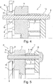
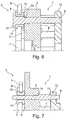
- jeweils eine Ladeeinrichtung mit einem erfinddungsgemäß auf einem Passstift angeordneten Rollen- oder Gleitlager zur Lagerung eines Verstellringes am Schaufellagerring.
- Entsprechend der
Fig. 1 weist eine lediglich teilweise dargestellte Ladeeinrichtung 1, welche beispielsweise als Abgasturbolader für ein Kraftfahrzeug ausgebildet ist, eine Leitschaufeleinrichtung 2 auf, mit welcher eine variable Turbinen- und/oder Verdichtergeometrie realisierbar ist. Die Leitschaufeleinrichtung 2 umfasst dabei zumindest einen Schaufellagerring 3 mit drehbar daran/darin gelagerten Leitschaufeln 4 sowie einem koaxial zum Schaufellagerring 3 angeordneten Verstellring 5, über welchen die Leitschaufeln 4 gemeinsam verstellbar sind. Wie derFig. 1 dabei zu entnehmen ist, sind die Leitschaufeln 4 mittels Schaufelzapfen 6 am Schaufellagerring 3 drehbar gelagert, wobei die Schaufelzapfen 6 den Schaufellagerring 3 axial durchsetzen und jeweils drehfest einenends mit der Leitschaufel 4 und anderenends mit einem Schaufelhebel 7 verbunden sind, welcher jeweils einen radial nach außen gerichteten Hebelkopf 8 trägt und damit in eine korrespondierende, nicht dargestellte Ausnehmung am Verstellring 5 eingreift. Eine Rotationsbewegung des Verstellringes 5 bezüglich des Schaufellagerringes 3 bewirkt somit eine gleichmäßige Drehbewegung sämtlicher Leitschaufeln 4 um deren Schaufelzapfen 6. - Um eine Lagerung des rotierbar bezüglich des Schaufellagerrings 3 ausgebildeten Verstellrings 5 konstruktiv möglichst einfach zu gestalten, ist erfindungsgemäß vorgesehen, dass eine Lagerung des Verstellringes 5 am Schaufellagerring 3 über Gleit- oder Rollenlager erfolgt, die jeweils auf einem, den Schaufellagerring 3 durchdringenden Passstift 9 angeordnet sind. Der Passstift 9 hat dabei zugleich die Aufgabe, einen Axialabstand des Schaufellagerringes 3 zu einem Gehäuse oder zu einem in diesem angeordneten Einlegeteil/Deckscheibenelement 10 zu definieren. Wie insbesondere der
Fig. 1 zu entnehmen ist, besteht zwischen dem Passstift 9 und dem Schaufellagerring 3 ein Radialspalt, wodurch eine zumindest gewisse radiale und axiale Verschieblichkeit des Schaufellagerrings3 in Bezug auf das Gehäuse 10 gegeben ist. Diese Verschieblichkeit ermöglicht es, Dehnungen und/oder Toleranzen besser ausgleichen zu können und vermindet zumindest die Gefahr eines Verklemmens der Leitschaufeln 4. - Gemäß der
Fig. 1 weist dabei das Rollenlager eine drehbar gelagerte Lagerrolle 11 auf, welche in Axialrichtung einerseits benachbart zum Schaufellagerring 3 und andererseits zu einem Axialanschlag 12, beispielsweise einer Mutter angeordnet ist. Der Abstand zwischen dem Schaufellagerring 3 einerseits und dem Gehäuse 10 andererseits wird bei der Ausführungsform gemäß derFig. 1 von zwei Radialstufen, nämlich einer zweiten Radialstufe 13 sowie einer dritten Radialstufe 14 begrenzt. Über die zweite Radialstufe 13 stützt sich der Passstift 9 am Einlegeteil/Deckscheibenelement 10 ab, während er sich über die dritte Radialstufe 14 am Schaufellagerring 3 abstützt. Derartige Radialstufen 13, 14 lassen sich besonders einfach, beispielsweise durch einen Drehvorgang herstellen und erübrigen somit eine in diesem Bereich vorzusehende Abstandshülse 15, wie diese beispielsweise in denFig. 5 ,6 ,8 und 9 vorgeschlagen ist. - Um auch den Axialanschlag 12 mit definiertem Axialabstand zum Schaufellagerring 3 festlegen zu können, kann eine weitere, nämlich eine vierte Radialstufe 16 vorgesehen sein, an welcher der Axialanschlag 12 in montiertem Zustand anliegt. Die Lagerrolle 11 ist dabei gemäß, der
Fig. 1 leichtgängig auf dem Passstift 9 gelagert, wobei der durch die Radialstufen 14 und 16 vorgegebene Axialabstand zwischen dem Axialanschlag 12 und dem Schaufellagerring 3 größer ist als die axiale Längserstreckung der Lagerrolle 11, so dass diese auf jeden Fall klemmfrei gelagert werden kann. Gleiches gilt auch für die Leitschaufeln 4, da der Axialabstand zwischen dem Gehäuse 10 und dem Schaufellagerring 3, der durch die zweite und dritte Radialstufe 13, 14 begrenzt ist, ein Einklemmen der Leitschaufeln 4 zwischen dem Schaufellagerring 3 und dem Einlegeteil/Deckscheibenelement 10 zuverlässig verhindert. - Anstelle des gemäß der
Fig. 1 dargestellten Axialanschlages 12 kann der Passstift 9 an seinem die Lagerrolle 11 tragenden Ende auch einen Kragen 17 aufweisen, wie dies beispielsweise in denFig. 6 und9 dargestellt ist. Dieser Kragen 17 bildet dabei eine andere Ausführungsform für einen Axialanschlag 12. Eine weitere Möglichkeit für einen Axialanschlag 12 bildet eine, einen Kragen aufweisende Lagerhülse 18, wie diese beispielsweise gemäß derFig. 2 dargestellt ist. Die Lagerhülse 18 ist dabei zwischen dem Passstift 9 und dem zugehörigen Rollenlager, das heißt der Lagerrolle 11, angeordnet, wobei die Lagerhülse 18 eine größere axiale Ausdehnung aufweist als die Lagerrolle 11, so dass diese mit Spiel zwischen dem Schaufellagerring 3 und dem Kragen der Lagerhülse 18 angeordnet ist. Dabei können die gemäß denFig. 1 bis 7 und9 gezeigten Lagerrollen 11 auch als Gleitlager ausgebildet sein, so dass diese nicht bezüglich des Passstiftes 9 drehbar gelagert sind, sondern der Verstellring 5 in einer Umfangsnut 19 der als Gleitlager ausgebildeten Lagerrolle 11 gelagert, insbesondere geführt ist. - Gemäß den
Fig. 4 und 5 ist der Passstift 9 ohne Radialstufen ausgebildet, weswegen in diesem Fall zur zuverlässigen Definition des Axialabstandes zwischen dem Schaufellagerring 3 einerseits und dem Einlegeteil/Deckscheibenelement 10 andererseits, der Passstift 9 sowohl mit dem Einlegeteil/Deckscheibenelement 10 als auch mit dem Schaufellagerring 3 fest verbunden, insbesondere verpresst ist. Auch bei diesen Ausführungsformen kann die Lagerrolle 11 als Gleitlager ausgebildet sein. - Betrachtet man die Ausführungsform gemäß der
Fig. 6 , so fällt auf, dass der Passstift 9 eine erste Radialstufe 20 aufweist, über welche sich dieser am Schaufellagerring 3 abstützt und wobei ein Axialabstand zwischen der ersten Radialstufe 20 und dem Kragen 17 des Passstiftes 9 größer ist als die axiale Ausdehnung der Lagerrolle 11, so dass diese mit Spiel zwischen dem Schaufellagerring 3 und dem Kragen 17 des Passstiftes 9 angeordnet werden kann. Auch in diesem Fall ist eine verklemmfreie Lagerung der Lagerrolle 11 gegeben. - Im Unterschied zur
Fig. 6 , bei welcher die Abstandshülse 15 stirnendseitig auf dem Einlegeteil/Deckscheibenelement 10 beziehungsweise dem Schaufellagerring 3 aufliegt, sind die Abstandshülsen 15 gemäß denFig. 8 und 9 jeweils in den Schaufellagerring 3 einerseits und in das Gehäuse 10 andererseits eingelassen. Hierdurch ist es möglich, den Passstift 9 thermisch von den die Leitschaufeln 4 umströmenden heißen Abgasen zu entkoppeln, wodurch der Passstift 9 insgesamt geschützt angeordnet ist. - Vorzugsweise ist bei allen dargestellten Ladeeinrichtungen 1 eine Befestigung des Passstiftes 9 am Einlegeteil/Deckscheibenelement 10 bzw. am Gehäuse mittels Nieten, Schrauben oder Schweißen vorgesehen. Dabei ist beispielsweise in den
Fig. 1-4 und7 der Passstift 9 in nicht vernietetem Zustand gezeigt. In denFig. 5 sowie 8 und 9 kann der Passstift 9 auch in das Einlegeteil/Deckscheibenelement 10 eingeschraubt werden. - Gemäß der
Fig. 8 ist an einem dem Verstellring 5 zugewandten Ende des Passstiftes 9 ein Lagerkopf 21 mit einer Umfangsnut 19 vorgesehen, in welcher der Verstellring 5 gleitend geführt ist. Generell gilt dabei für eine zuverlässige Lagerung des Verstellringes 5 am Schaufellagerring 3, dass zumindest drei Lagerrollen 11 oder drei Lagerköpfe 21 mit einem jeweils zwischen zwei Lagerrollen 11/Lagerköpfen 21 liegenden Winkelbereich von 120° vorgesehen sind. Selbstverständlich ist auch denkbar, dass vier oder mehr Lagerrellen 11 vorgesehen sind. - Durch die erfindungsgemäße Ladeeinrichtung 1 lässt sich eine besonders einfache und hoch funktionelle Lagerung des Verstellringes 5 am Schaufellagerring 3 realisieren, da die Passstifte 9, welche einen Axialabstand zwischen dem Schaufellagerring 3 und dem Einlegeteil/Deckscheibenelement 10 definieren, zugleich als Träger für die den Verstellring 5 lagernden Lagerrollen 11 beziehungsweise Lagerköpfe 21 fungieren. Dadurch wird zudem eine Reduktion der Teilevielfalt erreicht, wodurch sich auch die Lager- und Logistikkosten reduzieren lassen.
Claims (11)
- Ladeeinrichtung (1), insbesondere ein Abgasturbolader für ein Kraftfahrzeug, mit- einer variablen Turbinen- und/oder Verdichtergeometrie,- einer, in einem Gehäuse (10) angeordneten Leitschaufeleinrichtung (2), umfassend zumindest einen Schaufellagerring (3) mit drehbar daran/darin gelagerten Leitschaufeln (4) und einen koaxial zum Schaufellagerring (3) angeordneten und an diesem gelagerten Verstellring (5), der relativ zum Schaufellagerring (3) rotierbar ist und über welchen die Leitschaufeln (4) verstellbar sind,dadurch gekennzeichnet,
dass eine Lagerung des Verstellrings (5) am Schaufellagerring (3) über Gleit- oder Rollenlager erfolgt, die jeweils auf einem den Schaufellagerring (3) durchdringenden Passstift (9) angeordnet sind, wobei die Passstifte (9) einen Axialabstand des Schaufellagerrings (3) zum Gehäuse oder zu einem in diesem angeordneten Einlegeteil/Deckscheibenelement (10) definieren. - Ladeeinrichtung nach Anspruch 1,
dadurch gekennzeichnet,
dass auf jedem Passstift (9) ein Rollenlager mit einer drehbar gelagerten Lagerrolle (11) vorgesehen ist. - Ladeeinrichtung nach Anspruch 1 oder 2,
dadurch gekennzeichnet,
dass zumindest ein Passstift (9) an seinem das Rollenlager tragenden Ende einen Kragen (17) aufweist, der einen Axialanschlag (12) für das Rollenlager/die Lagerrolle (11) bildet. - Ladeeinrichtung nach Anspruch 3,
dadurch gekennzeichnet,
dass zumindest ein Passstift (9) eine erste Radialstufe (20) aufweist, über welche sich dieser am Schaufellagering (3) abstützt, wobei ein Axialabstand zwischen der ersten Radialstufe (20) und dem Kragen (17) des Passstiftes (9) größer ist als eine Axialausdehnung der Lagerrolle (11), so dass diese mit Spiel zwischen dem Schaufellagerring (3) und dem Kragen (17) des Passstiftes (9) angeordnet ist. - Ladeeinrichtung nach Anspruch 4,
dadurch gekennzeichnet,
dass zumindest ein Passstift (9) neben der ersten Radialstufe (20) eine zweite Radialstufe (13) aufweist, über welche sich der Passstift (9) am Gehäuse oder an einem in diesem angeordneten Einlegeteil/Deckscheibenelement (10) abstützt, wobei zwischen dem Schaufellagering (3) und dem Gehäuse/Einlegeteil/Deckscheibenelement (10) eine den Passstift (9) umgebende Abstandshülse (15) vorgesehen ist. - Ladeeinrichtung nach Anspruch 5,
dadurch gekennzeichnet,
dass die Abstandshülse (15) in der Art der zweiten Radialstufe (13) und einer axial dazu benachbarten dritten Radialstufe (14) ausgebildet ist, wobei sich der Passstift (9) über die zweite Radialstufe (14) am Gehäuse oder an dem in diesem angeordneten Einlegeteil/Deckscheibenelement (10) und über die dritte Radialstufe (14) am Schaufellagerring (3) abstützt. - Ladeeinrichtung nach Anspruch 5 oder 6,
dadurch gekennzeichnet,
dass die Abstandshülse (15) in den Schaufellagerring (3) und/oder in das Einlegeteil/Deckscheibenelement (10) eingelassen ist. - Ladeeinrichtung nach einem der Ansprüche 1 bis 7,
dadurch gekennzeichnet,
dass eine, einen Kragen aufweisende Lagerhülse (18) vorgesehen ist, die zwischen dem Passstift (9) und dem zugehörigen Rollenlager angeordnet ist, wobei die Lagerhülse (18) eine größere axiale Ausdehnung aufweist als das Rollenlager, so dass diese mit Spiel zwischen dem Schaufellagerring (3) und dem Kragen der Lagerhülse (18) angeordnet ist. - Ladeeinrichtung nach Anspruch 1,
dadurch gekennzeichnet,
dass an einem dem Verstellring (5) zugewandten Ende des Passstiftes (9) ein Lagerkopf (21) mit einer Umfangsnut (19) vorgesehen, in welcher der Verstellring (5) gleitend geführt ist. - Ladeeinrichtung nach einem der Ansprüche 1 bis 9,
dadurch gekennzeichnet,
dass drei Lagerrollen (11) oder drei Lagerköpfe (21) mit einem jeweils zwischen zwei Lagerrollen (11)/Lagerköpfen (21) liegenden Winkelbereich von 120° vorgesehen sind. - Verbrennungsmotor mit einer Ladeeinrichtung (1) nach einem der Ansprüche 1 bis 10.
Applications Claiming Priority (2)
| Application Number | Priority Date | Filing Date | Title |
|---|---|---|---|
| DE200710056154 DE102007056154A1 (de) | 2007-11-21 | 2007-11-21 | Ladeeinrichtung |
| PCT/EP2008/065453 WO2009065763A2 (de) | 2007-11-21 | 2008-11-13 | Ladeeinrichtung |
Publications (2)
| Publication Number | Publication Date |
|---|---|
| EP2209969A2 EP2209969A2 (de) | 2010-07-28 |
| EP2209969B1 true EP2209969B1 (de) | 2016-06-29 |
Family
ID=40576897
Family Applications (1)
| Application Number | Title | Priority Date | Filing Date |
|---|---|---|---|
| EP08851470.8A Not-in-force EP2209969B1 (de) | 2007-11-21 | 2008-11-13 | Ladeeinrichtung |
Country Status (4)
| Country | Link |
|---|---|
| US (1) | US8845279B2 (de) |
| EP (1) | EP2209969B1 (de) |
| DE (1) | DE102007056154A1 (de) |
| WO (1) | WO2009065763A2 (de) |
Families Citing this family (16)
| Publication number | Priority date | Publication date | Assignee | Title |
|---|---|---|---|---|
| DE102008000776B4 (de) * | 2008-01-21 | 2022-04-14 | BMTS Technology GmbH & Co. KG | Turbine mit varialber Turbinengeometrie, insbesondere für einen Abgasturbolader, sowie Abgasturbolader |
| DE102008005658A1 (de) | 2008-01-23 | 2009-07-30 | Bosch Mahle Turbo Systems Gmbh & Co. Kg | Ladeeinrichtung |
| DE102008014678B4 (de) * | 2008-03-18 | 2014-08-14 | Continental Automotive Gmbh | Turbolader mit einer variablen Turbinengeometrie VTG |
| DE102009009129B4 (de) | 2009-02-17 | 2022-11-03 | BMTS Technology GmbH & Co. KG | Turbolader mit variabler Turbinengeometrie |
| DE102009032452A1 (de) * | 2009-07-09 | 2011-01-13 | Bosch Mahle Turbo Systems Gmbh & Co. Kg | Ladeeinrichtung |
| DE102009052982A1 (de) * | 2009-10-31 | 2011-05-05 | Bosch Mahle Turbo Systems Gmbh & Co. Kg | Variable Turbinen- und/oder Verdichtergeometrie |
| US8668443B2 (en) | 2010-01-08 | 2014-03-11 | Honeywell International Inc. | Variable-vane assembly having unison ring guided radially by rollers and fixed members, and restrained axially by one or more fixed axial stops |
| DE102010004622B8 (de) * | 2010-01-14 | 2014-04-17 | Bosch Mahle Turbo Systems Gmbh & Co. Kg | Variable Turbinen- und/oder Verdichtergeometrie |
| DE102011083990A1 (de) | 2010-10-08 | 2012-07-05 | Bosch Mahle Turbo Systems Gmbh & Co. Kg | Variable Turbinen- und/oder Verdichtergeometrie |
| DE102010042181A1 (de) | 2010-10-08 | 2012-04-12 | Bosch Mahle Turbo Systems Gmbh & Co. Kg | Variable Turbinen- und/oder Verdichtergeometrie |
| CN103492688B (zh) * | 2011-05-10 | 2016-02-10 | 博格华纳公司 | 具有可变涡轮几何形状的涡轮增压器 |
| KR20140142318A (ko) * | 2012-04-03 | 2014-12-11 | 보르그워너 인코퍼레이티드 | 베인 링 조립체를 위한 유지 시스템 및 방법 |
| US9651053B2 (en) | 2014-01-24 | 2017-05-16 | Pratt & Whitney Canada Corp. | Bleed valve |
| US10087774B2 (en) * | 2014-09-29 | 2018-10-02 | Honeywell International Inc. | Turbocharger variable-vane cartridge with nozzle ring and pipe secured by two-piece self-centering spacers |
| DE102015209813A1 (de) * | 2015-05-28 | 2016-12-01 | Bosch Mahle Turbo Systems Gmbh & Co. Kg | Variable Turbinen- oder Verdichtergeometrie für einen Abgasturbolader |
| DE102016207698A1 (de) * | 2016-05-04 | 2017-11-09 | Bosch Mahle Turbo Systems Gmbh & Co. Kg | Ladeeinrichtung |
Family Cites Families (17)
| Publication number | Priority date | Publication date | Assignee | Title |
|---|---|---|---|---|
| US6145313A (en) | 1997-03-03 | 2000-11-14 | Allied Signal Inc. | Turbocharger incorporating an integral pump for exhaust gas recirculation |
| US5947681A (en) | 1997-03-17 | 1999-09-07 | Alliedsignal Inc. | Pressure balanced dual axle variable nozzle turbocharger |
| US6679057B2 (en) | 2002-03-05 | 2004-01-20 | Honeywell-International Inc. | Variable geometry turbocharger |
| DE10262006B4 (de) | 2002-03-05 | 2005-09-22 | Borgwarner Turbo Systems Gmbh | Turbolader für Fahrzeuge mit verbesserter Aufhängung für den Betätigungsmechanismus der variablen Düsen |
| DE10213897A1 (de) | 2002-03-28 | 2003-10-09 | Daimler Chrysler Ag | Variabler Abgasturbolader |
| JP4008404B2 (ja) * | 2002-10-18 | 2007-11-14 | 三菱重工業株式会社 | 可変容量型排気ターボ過給機 |
| DE10337495B4 (de) | 2003-08-14 | 2016-09-22 | Volkswagen Ag | Abgasturbolader für eine Brennkraftmaschine |
| DE10337491A1 (de) | 2003-08-14 | 2005-03-17 | Volkswagen Ag | Abgasturbolader für eine Brennkraftmaschine |
| DE102004023209A1 (de) | 2004-05-11 | 2005-12-08 | Volkswagen Ag | Abgasturbolader für eine Brennkraftmaschine mit variabler Turbinengeometrie |
| DE102004023279A1 (de) | 2004-05-11 | 2005-12-01 | Volkswagen Ag | Abgasturbolader für eine Brennkraftmaschine mit variabler Turbinengeometrie |
| DE102004037082A1 (de) | 2004-07-30 | 2006-03-23 | Volkswagen Ag | Abgasturbolader mit variabler Turbinengeometrie |
| DE102004057864A1 (de) | 2004-11-30 | 2006-06-01 | Borgwarner Inc.(N.D.Ges.D.Staates Delaware), Auburn Hills | Abgasturbolader, Leitapparat für einen Abgasturbolader sowie Schaufelhebel für einen Leitapparat |
| DE102005019938A1 (de) | 2005-04-29 | 2006-11-09 | Daimlerchrysler Ag | Abgasturbolader für eine Brennkraftmaschine |
| DE102006048514B3 (de) | 2005-12-01 | 2007-05-10 | Mtu Friedrichshafen Gmbh | Leiteinrichtung für einen VTG-Abgasturbolader |
| DE102006007347A1 (de) | 2006-02-17 | 2007-08-30 | Daimlerchrysler Ag | Verdichter für eine Brennkraftmaschine |
| DE102008014678B4 (de) | 2008-03-18 | 2014-08-14 | Continental Automotive Gmbh | Turbolader mit einer variablen Turbinengeometrie VTG |
| DE102008020932B4 (de) | 2008-04-25 | 2010-09-23 | Continental Automotive Gmbh | Turbolader mit einer variablen Turbinengeometrieeinrichtung |
-
2007
- 2007-11-21 DE DE200710056154 patent/DE102007056154A1/de not_active Withdrawn
-
2008
- 2008-11-13 US US12/744,143 patent/US8845279B2/en not_active Expired - Fee Related
- 2008-11-13 WO PCT/EP2008/065453 patent/WO2009065763A2/de not_active Ceased
- 2008-11-13 EP EP08851470.8A patent/EP2209969B1/de not_active Not-in-force
Non-Patent Citations (1)
| Title |
|---|
| None * |
Also Published As
| Publication number | Publication date |
|---|---|
| DE102007056154A1 (de) | 2009-05-28 |
| WO2009065763A3 (de) | 2010-01-14 |
| EP2209969A2 (de) | 2010-07-28 |
| US20100316489A1 (en) | 2010-12-16 |
| US8845279B2 (en) | 2014-09-30 |
| WO2009065763A2 (de) | 2009-05-28 |
Similar Documents
| Publication | Publication Date | Title |
|---|---|---|
| WO2009065763A2 (de) | Ladeeinrichtung | |
| EP1460237B1 (de) | Abgasturbinengehäuse | |
| EP2002127B1 (de) | Vordrall-leitvorrichtung | |
| EP2078136B1 (de) | Reibgeschweisste turboladerwelle und herstellungsverfahren dafür | |
| WO2009092678A1 (de) | Turbine; insbesondere für einen abgasturbolader; sowie abgasturbolader | |
| DE102009053102A1 (de) | Axiallageranordnung für eine Welle eines Turboladers | |
| WO2009092635A2 (de) | Ladeeinrichtung | |
| EP2845999A2 (de) | Verfahren zum Auswuchten und zur Montage eines Turbinenrotors | |
| DE102008020932A1 (de) | Turbolader mit einer variablen Turbinengeometrie VTG | |
| EP1420152A2 (de) | Abgasturbolader | |
| DE102009009130B4 (de) | Turbolader, vorzugsweise mit variabler Turbinengeometrie | |
| EP1881162B1 (de) | Abgasturbolader für eine Brennkraftmaschine | |
| EP1734231A1 (de) | Turbolader und Schaufellagerring hierfür | |
| EP1998026A2 (de) | Ladeeinrichtung | |
| DE102008020732A1 (de) | Ladeeinrichtung | |
| EP3176386B1 (de) | Innenringsystem, zugehöriger innenring, zwichengehäuse und strömungsmaschine | |
| DE102008000508A1 (de) | Abgasturbolader mit verstellbarer Turbinengeometrie | |
| DE102008060251B4 (de) | Abgasturbolader mit variabler Turbinengeometrie | |
| DE102008046009A1 (de) | Ladeeinrichtung | |
| WO2014121986A1 (de) | Ventileinheit für ein wastegatesystem und abgasturbolader | |
| EP2317081B1 (de) | Variable Turbinen- und/oder Verdichtergeometrie | |
| DE102008000724B4 (de) | Abgasturbolader mit verstellbarer Turbinengeometrie | |
| EP3491226B1 (de) | Klappeneinrichtung zum oeffnen und schliessen eines wastegatekanals in einem turbinengehaeuse eines turboladers, turbolader sowie verfahren zur herstellung | |
| DE102012211417A1 (de) | Leitschaufel-Anordnung für einen Abgasturbolader | |
| EP2796665B1 (de) | Abgasturbolader mit einer Welle aus unterschiedlichen Materialien |
Legal Events
| Date | Code | Title | Description |
|---|---|---|---|
| PUAI | Public reference made under article 153(3) epc to a published international application that has entered the european phase |
Free format text: ORIGINAL CODE: 0009012 |
|
| 17P | Request for examination filed |
Effective date: 20100505 |
|
| AK | Designated contracting states |
Kind code of ref document: A2 Designated state(s): AT BE BG CH CY CZ DE DK EE ES FI FR GB GR HR HU IE IS IT LI LT LU LV MC MT NL NO PL PT RO SE SI SK TR |
|
| AX | Request for extension of the european patent |
Extension state: AL BA MK RS |
|
| RIN1 | Information on inventor provided before grant (corrected) |
Inventor name: RENTZ, FLORIAN Inventor name: HOECKER, PATRIC Inventor name: REYNOLDS, IAN |
|
| DAX | Request for extension of the european patent (deleted) | ||
| 17Q | First examination report despatched |
Effective date: 20140224 |
|
| GRAP | Despatch of communication of intention to grant a patent |
Free format text: ORIGINAL CODE: EPIDOSNIGR1 |
|
| INTG | Intention to grant announced |
Effective date: 20160311 |
|
| GRAS | Grant fee paid |
Free format text: ORIGINAL CODE: EPIDOSNIGR3 |
|
| GRAA | (expected) grant |
Free format text: ORIGINAL CODE: 0009210 |
|
| AK | Designated contracting states |
Kind code of ref document: B1 Designated state(s): AT BE BG CH CY CZ DE DK EE ES FI FR GB GR HR HU IE IS IT LI LT LU LV MC MT NL NO PL PT RO SE SI SK TR |
|
| REG | Reference to a national code |
Ref country code: GB Ref legal event code: FG4D Free format text: NOT ENGLISH |
|
| REG | Reference to a national code |
Ref country code: CH Ref legal event code: EP |
|
| REG | Reference to a national code |
Ref country code: AT Ref legal event code: REF Ref document number: 809278 Country of ref document: AT Kind code of ref document: T Effective date: 20160715 |
|
| REG | Reference to a national code |
Ref country code: IE Ref legal event code: FG4D Free format text: LANGUAGE OF EP DOCUMENT: GERMAN |
|
| REG | Reference to a national code |
Ref country code: DE Ref legal event code: R096 Ref document number: 502008014344 Country of ref document: DE |
|
| REG | Reference to a national code |
Ref country code: LT Ref legal event code: MG4D |
|
| PG25 | Lapsed in a contracting state [announced via postgrant information from national office to epo] |
Ref country code: FI Free format text: LAPSE BECAUSE OF FAILURE TO SUBMIT A TRANSLATION OF THE DESCRIPTION OR TO PAY THE FEE WITHIN THE PRESCRIBED TIME-LIMIT Effective date: 20160629 Ref country code: NO Free format text: LAPSE BECAUSE OF FAILURE TO SUBMIT A TRANSLATION OF THE DESCRIPTION OR TO PAY THE FEE WITHIN THE PRESCRIBED TIME-LIMIT Effective date: 20160929 Ref country code: LT Free format text: LAPSE BECAUSE OF FAILURE TO SUBMIT A TRANSLATION OF THE DESCRIPTION OR TO PAY THE FEE WITHIN THE PRESCRIBED TIME-LIMIT Effective date: 20160629 |
|
| REG | Reference to a national code |
Ref country code: NL Ref legal event code: MP Effective date: 20160629 |
|
| REG | Reference to a national code |
Ref country code: FR Ref legal event code: PLFP Year of fee payment: 9 |
|
| PG25 | Lapsed in a contracting state [announced via postgrant information from national office to epo] |
Ref country code: LV Free format text: LAPSE BECAUSE OF FAILURE TO SUBMIT A TRANSLATION OF THE DESCRIPTION OR TO PAY THE FEE WITHIN THE PRESCRIBED TIME-LIMIT Effective date: 20160629 Ref country code: HR Free format text: LAPSE BECAUSE OF FAILURE TO SUBMIT A TRANSLATION OF THE DESCRIPTION OR TO PAY THE FEE WITHIN THE PRESCRIBED TIME-LIMIT Effective date: 20160629 Ref country code: SE Free format text: LAPSE BECAUSE OF FAILURE TO SUBMIT A TRANSLATION OF THE DESCRIPTION OR TO PAY THE FEE WITHIN THE PRESCRIBED TIME-LIMIT Effective date: 20160629 Ref country code: NL Free format text: LAPSE BECAUSE OF FAILURE TO SUBMIT A TRANSLATION OF THE DESCRIPTION OR TO PAY THE FEE WITHIN THE PRESCRIBED TIME-LIMIT Effective date: 20160629 Ref country code: GR Free format text: LAPSE BECAUSE OF FAILURE TO SUBMIT A TRANSLATION OF THE DESCRIPTION OR TO PAY THE FEE WITHIN THE PRESCRIBED TIME-LIMIT Effective date: 20160930 |
|
| PG25 | Lapsed in a contracting state [announced via postgrant information from national office to epo] |
Ref country code: IT Free format text: LAPSE BECAUSE OF FAILURE TO SUBMIT A TRANSLATION OF THE DESCRIPTION OR TO PAY THE FEE WITHIN THE PRESCRIBED TIME-LIMIT Effective date: 20160629 Ref country code: SK Free format text: LAPSE BECAUSE OF FAILURE TO SUBMIT A TRANSLATION OF THE DESCRIPTION OR TO PAY THE FEE WITHIN THE PRESCRIBED TIME-LIMIT Effective date: 20160629 Ref country code: IS Free format text: LAPSE BECAUSE OF FAILURE TO SUBMIT A TRANSLATION OF THE DESCRIPTION OR TO PAY THE FEE WITHIN THE PRESCRIBED TIME-LIMIT Effective date: 20161029 Ref country code: CZ Free format text: LAPSE BECAUSE OF FAILURE TO SUBMIT A TRANSLATION OF THE DESCRIPTION OR TO PAY THE FEE WITHIN THE PRESCRIBED TIME-LIMIT Effective date: 20160629 Ref country code: RO Free format text: LAPSE BECAUSE OF FAILURE TO SUBMIT A TRANSLATION OF THE DESCRIPTION OR TO PAY THE FEE WITHIN THE PRESCRIBED TIME-LIMIT Effective date: 20160629 Ref country code: EE Free format text: LAPSE BECAUSE OF FAILURE TO SUBMIT A TRANSLATION OF THE DESCRIPTION OR TO PAY THE FEE WITHIN THE PRESCRIBED TIME-LIMIT Effective date: 20160629 |
|
| PG25 | Lapsed in a contracting state [announced via postgrant information from national office to epo] |
Ref country code: PT Free format text: LAPSE BECAUSE OF FAILURE TO SUBMIT A TRANSLATION OF THE DESCRIPTION OR TO PAY THE FEE WITHIN THE PRESCRIBED TIME-LIMIT Effective date: 20161031 Ref country code: BE Free format text: LAPSE BECAUSE OF NON-PAYMENT OF DUE FEES Effective date: 20161130 Ref country code: ES Free format text: LAPSE BECAUSE OF FAILURE TO SUBMIT A TRANSLATION OF THE DESCRIPTION OR TO PAY THE FEE WITHIN THE PRESCRIBED TIME-LIMIT Effective date: 20160629 Ref country code: PL Free format text: LAPSE BECAUSE OF FAILURE TO SUBMIT A TRANSLATION OF THE DESCRIPTION OR TO PAY THE FEE WITHIN THE PRESCRIBED TIME-LIMIT Effective date: 20160629 |
|
| REG | Reference to a national code |
Ref country code: DE Ref legal event code: R097 Ref document number: 502008014344 Country of ref document: DE |
|
| PLBE | No opposition filed within time limit |
Free format text: ORIGINAL CODE: 0009261 |
|
| STAA | Information on the status of an ep patent application or granted ep patent |
Free format text: STATUS: NO OPPOSITION FILED WITHIN TIME LIMIT |
|
| PG25 | Lapsed in a contracting state [announced via postgrant information from national office to epo] |
Ref country code: DK Free format text: LAPSE BECAUSE OF FAILURE TO SUBMIT A TRANSLATION OF THE DESCRIPTION OR TO PAY THE FEE WITHIN THE PRESCRIBED TIME-LIMIT Effective date: 20160629 |
|
| 26N | No opposition filed |
Effective date: 20170330 |
|
| REG | Reference to a national code |
Ref country code: CH Ref legal event code: PL |
|
| PG25 | Lapsed in a contracting state [announced via postgrant information from national office to epo] |
Ref country code: CH Free format text: LAPSE BECAUSE OF NON-PAYMENT OF DUE FEES Effective date: 20161130 Ref country code: LI Free format text: LAPSE BECAUSE OF NON-PAYMENT OF DUE FEES Effective date: 20161130 |
|
| REG | Reference to a national code |
Ref country code: IE Ref legal event code: MM4A |
|
| PG25 | Lapsed in a contracting state [announced via postgrant information from national office to epo] |
Ref country code: SI Free format text: LAPSE BECAUSE OF FAILURE TO SUBMIT A TRANSLATION OF THE DESCRIPTION OR TO PAY THE FEE WITHIN THE PRESCRIBED TIME-LIMIT Effective date: 20160629 Ref country code: BG Free format text: LAPSE BECAUSE OF FAILURE TO SUBMIT A TRANSLATION OF THE DESCRIPTION OR TO PAY THE FEE WITHIN THE PRESCRIBED TIME-LIMIT Effective date: 20160929 |
|
| PG25 | Lapsed in a contracting state [announced via postgrant information from national office to epo] |
Ref country code: LU Free format text: LAPSE BECAUSE OF NON-PAYMENT OF DUE FEES Effective date: 20161130 |
|
| REG | Reference to a national code |
Ref country code: FR Ref legal event code: PLFP Year of fee payment: 10 |
|
| PG25 | Lapsed in a contracting state [announced via postgrant information from national office to epo] |
Ref country code: IE Free format text: LAPSE BECAUSE OF NON-PAYMENT OF DUE FEES Effective date: 20161113 |
|
| REG | Reference to a national code |
Ref country code: AT Ref legal event code: MM01 Ref document number: 809278 Country of ref document: AT Kind code of ref document: T Effective date: 20161113 |
|
| PG25 | Lapsed in a contracting state [announced via postgrant information from national office to epo] |
Ref country code: AT Free format text: LAPSE BECAUSE OF NON-PAYMENT OF DUE FEES Effective date: 20161113 |
|
| REG | Reference to a national code |
Ref country code: BE Ref legal event code: MM Effective date: 20161130 |
|
| PG25 | Lapsed in a contracting state [announced via postgrant information from national office to epo] |
Ref country code: HU Free format text: LAPSE BECAUSE OF FAILURE TO SUBMIT A TRANSLATION OF THE DESCRIPTION OR TO PAY THE FEE WITHIN THE PRESCRIBED TIME-LIMIT; INVALID AB INITIO Effective date: 20081113 Ref country code: CY Free format text: LAPSE BECAUSE OF FAILURE TO SUBMIT A TRANSLATION OF THE DESCRIPTION OR TO PAY THE FEE WITHIN THE PRESCRIBED TIME-LIMIT Effective date: 20160629 |
|
| REG | Reference to a national code |
Ref country code: DE Ref legal event code: R082 Ref document number: 502008014344 Country of ref document: DE Representative=s name: BRP RENAUD UND PARTNER MBB RECHTSANWAELTE PATE, DE Ref country code: DE Ref legal event code: R081 Ref document number: 502008014344 Country of ref document: DE Owner name: BMTS TECHNOLOGY GMBH & CO. KG, DE Free format text: FORMER OWNER: BOSCH MAHLE TURBO SYSTEMS GMBH & CO. KG, 70376 STUTTGART, DE |
|
| PG25 | Lapsed in a contracting state [announced via postgrant information from national office to epo] |
Ref country code: MC Free format text: LAPSE BECAUSE OF FAILURE TO SUBMIT A TRANSLATION OF THE DESCRIPTION OR TO PAY THE FEE WITHIN THE PRESCRIBED TIME-LIMIT Effective date: 20160629 Ref country code: TR Free format text: LAPSE BECAUSE OF FAILURE TO SUBMIT A TRANSLATION OF THE DESCRIPTION OR TO PAY THE FEE WITHIN THE PRESCRIBED TIME-LIMIT Effective date: 20160629 |
|
| PG25 | Lapsed in a contracting state [announced via postgrant information from national office to epo] |
Ref country code: MT Free format text: LAPSE BECAUSE OF FAILURE TO SUBMIT A TRANSLATION OF THE DESCRIPTION OR TO PAY THE FEE WITHIN THE PRESCRIBED TIME-LIMIT Effective date: 20160629 |
|
| PGFP | Annual fee paid to national office [announced via postgrant information from national office to epo] |
Ref country code: GB Payment date: 20201126 Year of fee payment: 13 Ref country code: FR Payment date: 20201126 Year of fee payment: 13 |
|
| PGFP | Annual fee paid to national office [announced via postgrant information from national office to epo] |
Ref country code: DE Payment date: 20210128 Year of fee payment: 13 |
|
| REG | Reference to a national code |
Ref country code: DE Ref legal event code: R119 Ref document number: 502008014344 Country of ref document: DE |
|
| GBPC | Gb: european patent ceased through non-payment of renewal fee |
Effective date: 20211113 |
|
| PG25 | Lapsed in a contracting state [announced via postgrant information from national office to epo] |
Ref country code: GB Free format text: LAPSE BECAUSE OF NON-PAYMENT OF DUE FEES Effective date: 20211113 Ref country code: DE Free format text: LAPSE BECAUSE OF NON-PAYMENT OF DUE FEES Effective date: 20220601 |
|
| PG25 | Lapsed in a contracting state [announced via postgrant information from national office to epo] |
Ref country code: FR Free format text: LAPSE BECAUSE OF NON-PAYMENT OF DUE FEES Effective date: 20211130 |