EP2207663B1 - Dispositif de soufflage-étirage et procédé de fabrication de préformes - Google Patents
Dispositif de soufflage-étirage et procédé de fabrication de préformes Download PDFInfo
- Publication number
- EP2207663B1 EP2207663B1 EP08840566A EP08840566A EP2207663B1 EP 2207663 B1 EP2207663 B1 EP 2207663B1 EP 08840566 A EP08840566 A EP 08840566A EP 08840566 A EP08840566 A EP 08840566A EP 2207663 B1 EP2207663 B1 EP 2207663B1
- Authority
- EP
- European Patent Office
- Prior art keywords
- injection
- melt
- mold
- rotor
- interior
- Prior art date
- Legal status (The legal status is an assumption and is not a legal conclusion. Google has not performed a legal analysis and makes no representation as to the accuracy of the status listed.)
- Not-in-force
Links
- 238000000071 blow moulding Methods 0.000 title claims description 11
- 238000004519 manufacturing process Methods 0.000 title abstract description 4
- 238000002347 injection Methods 0.000 claims abstract description 97
- 239000007924 injection Substances 0.000 claims abstract description 97
- 238000000034 method Methods 0.000 claims abstract description 49
- 239000000155 melt Substances 0.000 claims abstract description 38
- 238000001746 injection moulding Methods 0.000 claims abstract description 21
- 238000007664 blowing Methods 0.000 claims abstract description 14
- 229920003023 plastic Polymers 0.000 claims abstract description 8
- 238000000748 compression moulding Methods 0.000 claims abstract description 7
- 230000003750 conditioning effect Effects 0.000 claims description 52
- 238000001816 cooling Methods 0.000 claims description 16
- 238000003825 pressing Methods 0.000 claims description 4
- 239000000969 carrier Substances 0.000 claims description 3
- 239000007921 spray Substances 0.000 description 16
- 238000010438 heat treatment Methods 0.000 description 6
- 230000000903 blocking effect Effects 0.000 description 5
- 238000005562 fading Methods 0.000 description 4
- 238000000465 moulding Methods 0.000 description 3
- 238000013386 optimize process Methods 0.000 description 3
- 238000004904 shortening Methods 0.000 description 3
- 238000004140 cleaning Methods 0.000 description 2
- 239000002826 coolant Substances 0.000 description 2
- 238000009826 distribution Methods 0.000 description 2
- 239000008187 granular material Substances 0.000 description 2
- 230000002093 peripheral effect Effects 0.000 description 2
- 229920000426 Microplastic Polymers 0.000 description 1
- 230000005540 biological transmission Effects 0.000 description 1
- 230000003139 buffering effect Effects 0.000 description 1
- 230000001143 conditioned effect Effects 0.000 description 1
- 238000010276 construction Methods 0.000 description 1
- 230000001934 delay Effects 0.000 description 1
- 238000006073 displacement reaction Methods 0.000 description 1
- 230000000694 effects Effects 0.000 description 1
- 238000007654 immersion Methods 0.000 description 1
- 238000005457 optimization Methods 0.000 description 1
- 238000007493 shaping process Methods 0.000 description 1
- 239000002689 soil Substances 0.000 description 1
Images


Classifications
-
- B—PERFORMING OPERATIONS; TRANSPORTING
- B29—WORKING OF PLASTICS; WORKING OF SUBSTANCES IN A PLASTIC STATE IN GENERAL
- B29C—SHAPING OR JOINING OF PLASTICS; SHAPING OF MATERIAL IN A PLASTIC STATE, NOT OTHERWISE PROVIDED FOR; AFTER-TREATMENT OF THE SHAPED PRODUCTS, e.g. REPAIRING
- B29C49/00—Blow-moulding, i.e. blowing a preform or parison to a desired shape within a mould; Apparatus therefor
- B29C49/02—Combined blow-moulding and manufacture of the preform or the parison
- B29C49/06—Injection blow-moulding
-
- B—PERFORMING OPERATIONS; TRANSPORTING
- B29—WORKING OF PLASTICS; WORKING OF SUBSTANCES IN A PLASTIC STATE IN GENERAL
- B29C—SHAPING OR JOINING OF PLASTICS; SHAPING OF MATERIAL IN A PLASTIC STATE, NOT OTHERWISE PROVIDED FOR; AFTER-TREATMENT OF THE SHAPED PRODUCTS, e.g. REPAIRING
- B29C45/00—Injection moulding, i.e. forcing the required volume of moulding material through a nozzle into a closed mould; Apparatus therefor
- B29C45/03—Injection moulding apparatus
- B29C45/04—Injection moulding apparatus using movable moulds or mould halves
- B29C45/06—Injection moulding apparatus using movable moulds or mould halves mounted on a turntable, i.e. on a rotating support having a rotating axis parallel to the mould opening, closing or clamping direction
-
- B—PERFORMING OPERATIONS; TRANSPORTING
- B29—WORKING OF PLASTICS; WORKING OF SUBSTANCES IN A PLASTIC STATE IN GENERAL
- B29C—SHAPING OR JOINING OF PLASTICS; SHAPING OF MATERIAL IN A PLASTIC STATE, NOT OTHERWISE PROVIDED FOR; AFTER-TREATMENT OF THE SHAPED PRODUCTS, e.g. REPAIRING
- B29C45/00—Injection moulding, i.e. forcing the required volume of moulding material through a nozzle into a closed mould; Apparatus therefor
- B29C45/17—Component parts, details or accessories; Auxiliary operations
- B29C45/26—Moulds
- B29C45/27—Sprue channels ; Runner channels or runner nozzles
- B29C45/2725—Manifolds
-
- B—PERFORMING OPERATIONS; TRANSPORTING
- B29—WORKING OF PLASTICS; WORKING OF SUBSTANCES IN A PLASTIC STATE IN GENERAL
- B29C—SHAPING OR JOINING OF PLASTICS; SHAPING OF MATERIAL IN A PLASTIC STATE, NOT OTHERWISE PROVIDED FOR; AFTER-TREATMENT OF THE SHAPED PRODUCTS, e.g. REPAIRING
- B29C45/00—Injection moulding, i.e. forcing the required volume of moulding material through a nozzle into a closed mould; Apparatus therefor
- B29C45/17—Component parts, details or accessories; Auxiliary operations
- B29C45/46—Means for plasticising or homogenising the moulding material or forcing it into the mould
- B29C45/56—Means for plasticising or homogenising the moulding material or forcing it into the mould using mould parts movable during or after injection, e.g. injection-compression moulding
- B29C45/561—Injection-compression moulding
-
- B—PERFORMING OPERATIONS; TRANSPORTING
- B29—WORKING OF PLASTICS; WORKING OF SUBSTANCES IN A PLASTIC STATE IN GENERAL
- B29C—SHAPING OR JOINING OF PLASTICS; SHAPING OF MATERIAL IN A PLASTIC STATE, NOT OTHERWISE PROVIDED FOR; AFTER-TREATMENT OF THE SHAPED PRODUCTS, e.g. REPAIRING
- B29C49/00—Blow-moulding, i.e. blowing a preform or parison to a desired shape within a mould; Apparatus therefor
- B29C49/02—Combined blow-moulding and manufacture of the preform or the parison
- B29C2049/023—Combined blow-moulding and manufacture of the preform or the parison using inherent heat of the preform, i.e. 1 step blow moulding
-
- B—PERFORMING OPERATIONS; TRANSPORTING
- B29—WORKING OF PLASTICS; WORKING OF SUBSTANCES IN A PLASTIC STATE IN GENERAL
- B29C—SHAPING OR JOINING OF PLASTICS; SHAPING OF MATERIAL IN A PLASTIC STATE, NOT OTHERWISE PROVIDED FOR; AFTER-TREATMENT OF THE SHAPED PRODUCTS, e.g. REPAIRING
- B29C2949/00—Indexing scheme relating to blow-moulding
- B29C2949/20—Preforms or parisons whereby a specific part is made of only one component, e.g. only one layer
- B29C2949/22—Preforms or parisons whereby a specific part is made of only one component, e.g. only one layer at neck portion
-
- B—PERFORMING OPERATIONS; TRANSPORTING
- B29—WORKING OF PLASTICS; WORKING OF SUBSTANCES IN A PLASTIC STATE IN GENERAL
- B29C—SHAPING OR JOINING OF PLASTICS; SHAPING OF MATERIAL IN A PLASTIC STATE, NOT OTHERWISE PROVIDED FOR; AFTER-TREATMENT OF THE SHAPED PRODUCTS, e.g. REPAIRING
- B29C2949/00—Indexing scheme relating to blow-moulding
- B29C2949/20—Preforms or parisons whereby a specific part is made of only one component, e.g. only one layer
- B29C2949/24—Preforms or parisons whereby a specific part is made of only one component, e.g. only one layer at flange portion
-
- B—PERFORMING OPERATIONS; TRANSPORTING
- B29—WORKING OF PLASTICS; WORKING OF SUBSTANCES IN A PLASTIC STATE IN GENERAL
- B29C—SHAPING OR JOINING OF PLASTICS; SHAPING OF MATERIAL IN A PLASTIC STATE, NOT OTHERWISE PROVIDED FOR; AFTER-TREATMENT OF THE SHAPED PRODUCTS, e.g. REPAIRING
- B29C2949/00—Indexing scheme relating to blow-moulding
- B29C2949/20—Preforms or parisons whereby a specific part is made of only one component, e.g. only one layer
- B29C2949/26—Preforms or parisons whereby a specific part is made of only one component, e.g. only one layer at body portion
-
- B—PERFORMING OPERATIONS; TRANSPORTING
- B29—WORKING OF PLASTICS; WORKING OF SUBSTANCES IN A PLASTIC STATE IN GENERAL
- B29C—SHAPING OR JOINING OF PLASTICS; SHAPING OF MATERIAL IN A PLASTIC STATE, NOT OTHERWISE PROVIDED FOR; AFTER-TREATMENT OF THE SHAPED PRODUCTS, e.g. REPAIRING
- B29C2949/00—Indexing scheme relating to blow-moulding
- B29C2949/20—Preforms or parisons whereby a specific part is made of only one component, e.g. only one layer
- B29C2949/28—Preforms or parisons whereby a specific part is made of only one component, e.g. only one layer at bottom portion
-
- B—PERFORMING OPERATIONS; TRANSPORTING
- B29—WORKING OF PLASTICS; WORKING OF SUBSTANCES IN A PLASTIC STATE IN GENERAL
- B29C—SHAPING OR JOINING OF PLASTICS; SHAPING OF MATERIAL IN A PLASTIC STATE, NOT OTHERWISE PROVIDED FOR; AFTER-TREATMENT OF THE SHAPED PRODUCTS, e.g. REPAIRING
- B29C2949/00—Indexing scheme relating to blow-moulding
- B29C2949/30—Preforms or parisons made of several components
- B29C2949/3024—Preforms or parisons made of several components characterised by the number of components or by the manufacturing technique
-
- B—PERFORMING OPERATIONS; TRANSPORTING
- B29—WORKING OF PLASTICS; WORKING OF SUBSTANCES IN A PLASTIC STATE IN GENERAL
- B29C—SHAPING OR JOINING OF PLASTICS; SHAPING OF MATERIAL IN A PLASTIC STATE, NOT OTHERWISE PROVIDED FOR; AFTER-TREATMENT OF THE SHAPED PRODUCTS, e.g. REPAIRING
- B29C2949/00—Indexing scheme relating to blow-moulding
- B29C2949/30—Preforms or parisons made of several components
- B29C2949/3056—Preforms or parisons made of several components having components being compression moulded
-
- B—PERFORMING OPERATIONS; TRANSPORTING
- B29—WORKING OF PLASTICS; WORKING OF SUBSTANCES IN A PLASTIC STATE IN GENERAL
- B29C—SHAPING OR JOINING OF PLASTICS; SHAPING OF MATERIAL IN A PLASTIC STATE, NOT OTHERWISE PROVIDED FOR; AFTER-TREATMENT OF THE SHAPED PRODUCTS, e.g. REPAIRING
- B29C45/00—Injection moulding, i.e. forcing the required volume of moulding material through a nozzle into a closed mould; Apparatus therefor
- B29C45/17—Component parts, details or accessories; Auxiliary operations
- B29C45/26—Moulds
- B29C45/27—Sprue channels ; Runner channels or runner nozzles
- B29C45/28—Closure devices therefor
- B29C45/2806—Closure devices therefor consisting of needle valve systems
-
- B—PERFORMING OPERATIONS; TRANSPORTING
- B29—WORKING OF PLASTICS; WORKING OF SUBSTANCES IN A PLASTIC STATE IN GENERAL
- B29C—SHAPING OR JOINING OF PLASTICS; SHAPING OF MATERIAL IN A PLASTIC STATE, NOT OTHERWISE PROVIDED FOR; AFTER-TREATMENT OF THE SHAPED PRODUCTS, e.g. REPAIRING
- B29C49/00—Blow-moulding, i.e. blowing a preform or parison to a desired shape within a mould; Apparatus therefor
- B29C49/28—Blow-moulding apparatus
- B29C49/30—Blow-moulding apparatus having movable moulds or mould parts
- B29C49/36—Blow-moulding apparatus having movable moulds or mould parts rotatable about one axis
-
- B—PERFORMING OPERATIONS; TRANSPORTING
- B29—WORKING OF PLASTICS; WORKING OF SUBSTANCES IN A PLASTIC STATE IN GENERAL
- B29K—INDEXING SCHEME ASSOCIATED WITH SUBCLASSES B29B, B29C OR B29D, RELATING TO MOULDING MATERIALS OR TO MATERIALS FOR MOULDS, REINFORCEMENTS, FILLERS OR PREFORMED PARTS, e.g. INSERTS
- B29K2105/00—Condition, form or state of moulded material or of the material to be shaped
- B29K2105/25—Solid
- B29K2105/253—Preform
Definitions
- the invention relates to a device according to the preamble of patent claim 1 and a method according to the preamble of claim 21.
- a central stationary extruder alternately feeds two spray rotors via a 2-way control valve.
- one is a spray rotor, while the other spray rotor is driven in rotation and passes the preforms to a Transferstem with cooling devices.
- a rotary distributor is arranged, which feeds the injection molds sequentially via controlled injection valves. The respective injection valve is opened only when the injection mold is previously closed and fixed with internal mandrel retracted into the end position.
- a known device is a central extruder stationary. Sequentially controlled needle valves fill the cavities of four injection molds combined into a single unit. The spray rotor stops. The scope of the spray rotor four rotary-driven Blasrotoren are assigned. Transfer grippers engage the mouths of the preforms to transfer them in groups.
- two extruders are provided which operate continuously and are mounted diametrically opposite to a disc-shaped carrier.
- the carrier rotates about its axis to a respective dispensing position, stops in the dispensing position, or is at least substantially retarded before a strand exiting the extruder is separated and transferred to a stretch blow mold disposed thereunder.
- the invention has for its object to optimize a device of the type mentioned for an efficient Eintrenfrac with high output. Part of the object is also to provide an improved method for producing the preforms themselves.
- the aim is to make possible a one-step process with continuous optimization of the number of cavities, which takes place continuously without delays or intermediate stops, enabling a small extruder size, the device being characterized by low mold costs and a service-friendly modular design.
- the aim is to shorten the injection time and possible dead times, to achieve a high preform quality by gentle treatment of the melt, thereby increasing the power per cavity, and to save energy through an optimized process sequence.
- the device results from the at least co-rotating extruder head and the rotary distributor a high, possibly by a melt pump reinforced, realizable injection pressure with a shorter process time, with a small extruder size is sufficient and the possibly high number of cavities of injection molds is optimally used.
- a shortening of the injection time and the dead times can be achieved, since the injection mold does not need to be completely closed at the beginning of the process, ie, the die form can still be open or lifted.
- the initially flowing under low pressure melt is not immediately cooled by the cold inner mandrel, but can at least in
- the entire extruder is rotatably drivable together with the injection rotor.
- the extruder can be attached from above or from below, preferably separable, to the injection rotor.
- the extruder which is suitably arranged vertically at the top, has a rotationally drivable pressure section comprising the extruder mouthpiece and a stationary feed section.
- the feed section is preferably fixed relative to the injection rotor by means of a torque support and enables the convenient supply of granules, for example via one or more stationarily arranged feed devices.
- a sealed rotary joint is provided between the pressure section and the feed section so that the extruder mouthpiece rotates with the pressure section while the feed section is stationary.
- the rotary distributor which rotates with the extruder mouthpiece and the spray rotor, a connected to the extruder head, preferably decoupled, multichannel disc on which, preferably heated, casings or hot runners with mounted in mold carriers of the spray rotor, controlled Needle valves are connected.
- the extruder head preferably decoupled, multichannel disc on which, preferably heated, casings or hot runners with mounted in mold carriers of the spray rotor, controlled Needle valves are connected.
- each injection mold has a bottom and hull shape, an openable, preferably cooled, mouthpiece shape, and an axially displaceable, preferably internally cooled, internal mandrel that is adjustable through the die shape. This allows a precisely controllable temperature distribution in the preform.
- each injection mold has a bottom and a hull shape and a mouth mold which is openable together with an internally cooled and internally hollow inner mandrel relative to the bottom and hull shape.
- the melt injection valve is a metering needle valve connectable to the inner mandrel to feed the cavity through the hollow inner mandrel.
- the metering needle valve injects a precisely predetermined dose of the melt, with the dose being such as to avoid fading in the preform. Since the melt is fed through the hollow inner mandrel, the bottom and hull shape can be made simpler.
- the hollow inner mandrel is cooled, as well as the bottom and hull form, to optimize the temperature distribution in the preform.
- the inner mandrel has a continuous and in the region of the free Domendes emptying inner channel into which via the metering needle valve, the melt dose is introduced into the cavity.
- a needle is arranged, which can be moved between a retracted feed position via a melt Nachd Weghub into a closing the mouth of the inner channel closing position.
- the total melt dose is controlled by the Dosing needle valve introduced into the cavity, in three consecutive or adjoining steps. First, a first portion of the dose is introduced with the inner mandrel lifted out of the cavity through the inner channel of the inner mandrel at low pressure into the cavity until a level below the point of the mouth shape is achieved there.
- the inner mandrel is lowered together with the mouth mold, whereby the initial melt filling is displaced under low pressure by the immersion of the inner mandrel towards the mouth of the mouth.
- the mouth shape is blocked with the bottom and hull shape, and the inner mandrel has reached its lower end position and was fixed, ie, the cavity is sealed, the second part of the melt dose from the metering needle valve is injected through the inner channel, too the area of the mouth shape is filled.
- a residual volume of melt remains in the inner channel.
- This remaining melt volume is finally pressed by inserting the needle through the inner channel of the inner mandrel in a Nachdrückphase into the cavity to prevent fading. The needle is pressed until it finally closes the mouth of the inner channel of the inner mandrel.
- This stamp presses the remaining melt volume from the inner channel into the cavity and finally closes the mouth.
- the mouth mold is lifted out of the cavity together with the inner mandrel, wherein the preform remains on the inner mandrel.
- the mouth shape is opened and the preform is removed from the inner mandrel and transferred to the conditioning section.
- the needle with the punch is pulled back so far that the inner channel of the inner mandrel is free to feed the next dose of melt again.
- the stamp closes the inner channel upwards.
- transfer expanding mandrels which are operable to remove the preforms from the open mouthpiece shape.
- Each preform is gripped inside the mouthpiece and in the conditioning section Precisely conditioned to have the correct temperature profile for stretch blow molding, especially in those areas where the highest deformations occur during stretching and bladder, while the mouthpiece remains cool with the final shape in the injection mold and along the conditioning line.
- an infeed star is provided with transfer elements for preforms removed from the transfer expansion mandrels between the blower rotor and the conditioning section.
- each injection mold each has openable bottom and hull shapes and a, preferably cooled, mouthpiece shape and a movable through the mouthpiece shape and removable from the injection mold inner mandrel.
- the inner mandrel serves as a support for the preform during the entire injection process and in the conditioning section, and is not cooled, for example.
- each inner mandrel can be cooled down along the conditioning section to such an extent that during the injection process it does not exert any undesirable temperature influence on the resulting preform.
- the removable inner mandrel is expediently provided with an adapter part on which transfer grippers arranged on a link chain of the conditioning section engage in order to remove or take over the inner mandrel with the preform and to transport it along the conditioning section.
- a preform removal and transfer device is provided in or along the condition route, for example a cam-controlled lowering device with which the preforms can be removed from the inner mandrels and attached to one Inlet star of Blasotor cooperating transfer star are transferable.
- an openable and removable mouthpiece shape is included in each injection mold.
- the remaining in the injection mold inner mandrel is suitably cooled inside.
- the mouthpiece shape is removed together with the finished preform by means of transfer elements and transported at least along the conditioning section, preferably even into blow molds of the blower rotor, so that in this case each die shape serves as a transfer element remaining on the preform and used again in the blow mold.
- a pneumatic cylinder with a toggle mechanism is assigned.
- the closing force of the mouthpiece shape is, however, caused by blocking with the hull shape and / or the inner mandrel.
- the inner mandrel is expediently adjusted by a hydraulic cylinder which applies a high closing force, e.g. a hydraulic cylinder with a capacity of about 8 tons.
- the conditioning path is even variable in length. This can be done either by an adjustment or by replacing the link chain and displacement of a deflection mechanism.
- the conditioning section may be a rotor-shaped conditioning circuit, which peripherally carries a link chain with transfer expanding mandrels.
- the conditioning section can be designed as an elongated conditioning loop with a peripheral link chain and, for example, inner mandrel transfer grippers arranged thereon.
- the conditioning section designed as a conditioning circuit between the injection rotor and the inlet star is expediently assigned at least one preform cooling station.
- At least one cooling station with which the inner dome is cooled down on the return path, is provided on the conditioning section, which is in the form of a conditioning loop, between the transfer star and the spray rotor.
- conditioning section formed as a conditioning circuit as a division delay section in which the preform rotates.
- the procedure in the production of high-quality preforms, is such that initially only part of the cavity, in the absence of the inner mandrel, is filled with melt from the needle valve under low pressure, to a level below the mouth shape. Thereafter, this melt filling is displaced by adjusting the inner mandrel in the direction of the end position under slight pressure in the direction of the mouth shape. Only then is the inner mandrel fixed in the end position, before the rest of the melt volume is injected under elevated pressure.
- melt can spread favorably, before then the inner mandrel displaced by displacing melt in the direction of the mouthpiece shape in the final position and is blocked with the required closing force with the mouthpiece shape. Then the cavity is closed and the remaining volume of melt is metered under high pressure from the needle valve until the preform is completed.
- an injection phase is superimposed on the injection molding of the preform in order to prevent shrinkage.
- the cavity is initially with still pulled out internal mandrel and lifted mouth shape Partially filled by the inner mandrel with low pressure.
- the inner mandrel is lowered with the mouth shape and takes place the blocking, wherein the initial melt filling is displaced under slight pressure from the submerged inner mandrel.
- the remainder of the melt dose with the exception of the remaining melt volume in the inner channel of the inner mandrel, is brought into the cavity.
- the metering needle valve has been closed, a needle is pushed through the inner channel to press in the Nachdrückphase the remaining volume of melt into the cavity and thus prevent fading.
- the mouthpiece shape can first be closed or placed on the hull shape and / or the inner mandrel can only be retracted after sufficient melt has been introduced into one part of the cavity without contact with the inner mandrel. This saves process time and initially allows low pressure.
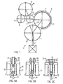
- Fig. 1 is a device V for stretch blow molding of plastic containers, in particular PET bottles, shown in a one-step process in plan view.
- the individual components of the device V are arranged in modular construction compact to each other, and comprise a spray rotor 1, which is combined with an at least partially co-rotating extruder 2 and cooperates with an adjacent, designed here as Konditionier conditioning 3, whose several cooling and / or heating stations assigned.
- the conditioning section 3 cooperates with a feed star 5, which in turn cooperates with a blowing rotor 6 for stretch blow molding of the containers, from which finished containers are removed via a discharge star 7 in the direction of the arrow 8.
- transfer expanding mandrels 40 are provided as transfer elements on movable arms of a division delay star 43.
- the inlet star 5 likewise has transport or transfer elements which transfer preforms P coming from the injection rotor 1 to blow molds 50 of the blowing rotor 6.
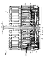
- the injection rotor 1 is arranged rotatably driven on a lower side support 9 and equipped with arranged in tie rods 28 having carriers injection molds 10.
- a rotary distributor 11th arranged, which includes a multi-channel disk 12 and to controlled needle valves 14 in the injection molds 10 extending piping 13 (hot runners with heating).
- a media rotary distributor 15 for working media of the spray rotor 1 is arranged centrally below (cooling medium, cleaning medium, heating medium, compressed air, hydraulic medium, control or supply current, and the like).
- Each injection mold 10 includes an inner mandrel 16 linearly displaceable by means of a hydraulic or servo-operated closure spindle 20 (hereinafter referred to as a servo), a one-piece or split bottom and body mold 17, and a split mouth mold 19.
- a servo a hydraulic or servo-operated closure spindle 20
- Each mouth mold 19 becomes by means of a pneumatic cylinder 21 and a in Fig. 3 shown toggle mechanism 30 is opened or closed and blocked by means of the hydraulic cylinder or servo 20 via the inner mandrel 16 in the closed position by Konusform gleich.
- the inner mandrel 16 is cooled inside, and the mouth mold 19 is cooled.
- the central extruder 2 is substantially in the axis X of the spray rotor 1 and above (alternatively below), wherein at least the extruder mouthpiece with the injection rotor 1 rotates synchronously.
- the extruder housing is divided into a high pressure part 23 with the extruder mouthpiece and a feed part 24.
- the high pressure part 23 cooperates with the charging part 24 via a sealed rotary joint 22, such that the charging part 24 is stationary when the high pressure part 23 rotates, for example, held by a torque arm 25 relative to the injection rotor 1.
- Inside the housing of the extruder 2 there is at least one extruder screw 26, not further emphasized, which rotates with a relative movement to the high-pressure part (23).
- the extruder is e.g. supplied via at least one stationary granule feed screw 27 with plastic granules.
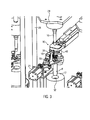
- Fig. 3 illustrates the opened injection mold 10, to which access is possible through the columns 28 and a support plate 29 of a mold holder from four sides.
- the pneumatic cylinder 21 has the mouth shape 19 via the toggle mechanism 30 already opened.
- a closing cone 31 can be seen, which cooperates with a counter-cone in a support of the inner mandrel 16 to build up the required closing pressure in the closed position of the mouth mold 19.
- the finished preform P is pulled out of a cavity 32 of the fuselage and bottom mold 17 by a stiinverstellterrorism the mouth shape 19 and already coupled to an unspecified transfer spreader 40 (or a laterally moved gripper), which brings the preform P in the conditioning section 3.
- the hull and bottom mold 17 need not be divisible or openable.
- the transfer expansion mandrel 40 engages the inside of the mouth of the preform P, which is stable in this phase of operation and has a low temperature.
- the transfer expanding mandrel 40 is then transferred with the preform at a Decision-makingsstem 43 in the conditioning section 3, wherein the transfer expanding mandrel 40 rotates and the preform on the cooling stations 4 conveyed until the correct temperature profile is achieved.
- grippers 41 take over the respective preform at the inlet star 5 and transfer this to a blow mold 50 of the blower rotor 6. In the further rotation of the blower rotor 6, the usual stretch blow molding process takes place.
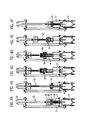
- Fig. 4A the injection mold is still closed after completion of an injection process.
- the needle valve 14 locks.
- a carrier 33 of the inner mandrel 16 interlocks the closed mouth shape 19.
- the toggle mechanism 30 is closed.
- Fig. 4E For example, the mouthpiece forming mechanism 34 is retracted and lowered and the mouthpiece mold 19 is closed. The inner mandrel 16 is lowered.
- Fig. 4F is the inner mandrel 16 reached in its lower end position and interlocked with the mouth mold 19, which in turn is also locked to the hull and bottom mold 17.
- the needle valve 14 opens and a new injection process begins.
- the sequence of movements in the Figs. 4A to 4F may be useful to modify something to a method according to the Figs. 5A to 5C in which an injection molding operation is combined or superimposed with a compression molding process.
- melt 35 dosed under low pressure initially in the cavity 32 of the bottom and hull form 17 flows.
- Fig. 4F will now only with still open needle valve in Fig.
- Fig. 7 the injection mold 10 is shown in disassembled state.
- the inner mandrel 16 is pulled out of the carrier 48 with its carrier 33.
- the inner mandrel has cooling channels 53 which communicate with cooling channels 52 in the carrier 48 as soon as the carrier 33 is inserted.
- a locking cone 54 is formed at the bottom of the carrier 33 for cooperation with the locking cone 31 of the mouth mold 19, and also in the hull shape 17 c, a locking cone 55 is formed.
- the bottom mold 17b and the hull mold 17c are successively inserted into a sleeve 49 mounted adjacent to the needle valve 14 in the mold holder 28, 29 and containing channels 51 for cooling and / or heating formed with in the hull mold 17c and bottom mold 17b Channels 56 communicate.
- the toggle mechanism 30 is in Fig. 7 released from the mouth 19.
- the respective inner mandrel 16 serves during the injection process and along the Konditionierrange as a carrier for the preform P.
- the inner mandrel 16 is not inside cooled.
- a conditioning section 3a which is designed as a conditioning loop with the link chain 43, which also extends around the injection rotor 1.
- the conditioning section 3a can, as indicated at 37, be variable in length.
- grippers 39 are arranged, which are rotatable, for example, in the direction of an arrow 46 along the conditioning section 3a, and serve in Fig. 9 shown adapter parts 44 of the inner mandrels 16 to take.
- a transfer star 42 is arranged, which is equipped, for example, with grippers 40 (eg expanding mandrels).
- the grippers 40 take over the preforms P from a take-off and transfer device 38 in the conditioning section 3a.
- the acceptance and transfer device 38 is, for example, a lowering device for the preforms transported from the inner mandrels 16.
- a cooling station 4 between the transfer star 42 and the injection rotor 1 can be used for cooling the inner dome 16 on the way back into the injection rotor 1. Further heating and / or cooling stations, not shown, can be used to condition the preforms on the inner mandrels 16.
- the transfer star 42 associated with preform cooling stations.
- device V is composed in modular design of individual optionally combinable modules in a compact arrangement.
- Fig. 9 illustrates that in each injection mold 10, the bottom and hull shape 17a is divisible and openable, and already contains the mouth shape 19 in openable version.
- the inner mandrel 16 carries at the top the adapter part 44, on which the gripper 39 acts on the link chain 34 in order to remove the inner mandrel 16 carrying the preform P from the opened injection mold 10 and into the conditioning section 3a convict.
- each inner mandrel 16 is moved after lifting transversely to the gripper 39 which is provided on the link chain 34.
- the inner mandrel 16 can be held like a bottom mold.
- the bottom and hull form 17 can be opened and closed together with the mouth shape 19 by a pneumatic cylinder 21, not shown, and a toggle mechanism 30.
- the grippers 39 on the link chain 43 are designed so that they release the inner mandrel 16 in the injection rotor 1, and rotate along the Konditionierrange.
- the take-off and transfer device 38 removes the preform P brought to the desired temperature profile from the inner mandrel 16 by pulling it downwards and transfers the preform to the transfer star 42. Subsequently, the empty inner mandrels 16 are cooled during the return transport into the injection molds 10.
- the co-rotating extruder 2 is arranged centrally and, for example, above by means of a torque support, according to the embodiment in FIG Fig. 2 with the rotary distributor 11 arranged below the extruder mouthpiece, from which the individual needle valves 14 below the injection mold 10 are supplied.
- the needle valves 14 belong to the machine module.
- the modular design is service-friendly.
- each mouth mold 19 may have an adapter part which is gripped by a gripper 39 and guided out of the injection mold 10 with the closed mouth mold 19 with preform P placed therein.
- the mouth mold 19 remains closed and is opened only in the acceptance and transfer device 38 in the conditioning section 3 a, before, for example, an expanding mandrel of the transfer star 42 takes over the preform P.
- the closed mouth shapes 19 are even transferred directly into the blow molds 50 of the blower rotor 6, so that they also act as molded parts in the stretch blow molding process. However, then a return device, not shown, for the mouth shapes 19 is required.
- the cycle time for stretch blow molding may be shorter than the cycle time for injection molding of a preform
- the injection mold 10 has a bottom and hull shape 17 (one-piece or two-piece) in which a part of the cavity 32 is defined.
- the mouth mold 19 is movable relative to the bottom and hull form 17 together with the inner mandrel 16.
- the inner mandrel 16 has in this embodiment a continuous inner channel 61, which ends at the free end of the inner mandrel 16 at an orifice 59.
- cooling channels 52 are connected in order to cool the internally cooled inner mandrel 16 and possibly also the mouth mold 19.
- the bottom and hull form 17 also has cooling channels, not shown.
- a nozzle 56 is provided, to which the melt injection valve is connected, which is formed in this embodiment as a metering needle valve 14 and each introduces a precisely metered dose controlled.
- a needle 57 is slidably guided, which is formed at the free end as a punch 60 which is fitted relatively tight in the inner channel 61.
- To the metering needle valve 14 performs an unspecified highlighted heating channel for the melt.
- process phase is removed with the inner mandrel 16 and closed mouth shape 19 from the metering needle valve 14 via the inner channel 61 melt introduced into the cavity 32 at low pressure, which fills a lower part of the cavity 32.
- the needle 57 is in its upper Feed position in which it closes the inner channel 61 upwards and releases the flow connection from the metering needle valve into the inner channel 61.
- Fig. 10D In the process phase in Fig. 10D is after the completion of the preform P of the inner mandrel 16 has been raised together with the mouth mold 19 relative to the bottom and hull form 17, wherein the preform P remains on the inner mandrel 16 and in the mouth mold 19 and is pulled out of the cavity 32. Thereafter, the mouth mold 19 is opened and the preform P is removed and transferred into the conditioning section. Simultaneously or trailing the needle 57 is pulled back to its upper feed position to release the connection between the metering needle valve 14 and the inner channel 61. This is followed by the process step accordingly Fig. 10A ,
- the mouth shape 19 also remain on the bottom and hull form 17, while the Inner mandrel 16 is moved. To remove the preform P, however, the mouth 19 must be opened beforehand so that the preform can be pulled out of the cavity 32 with the inner mandrel 16.
Landscapes
- Engineering & Computer Science (AREA)
- Manufacturing & Machinery (AREA)
- Mechanical Engineering (AREA)
- Blow-Moulding Or Thermoforming Of Plastics Or The Like (AREA)
- Moulds For Moulding Plastics Or The Like (AREA)
- Processing And Handling Of Plastics And Other Materials For Molding In General (AREA)
Claims (25)
- Dispositif (V) pour le soufflage-étirage de récipients en matière plastique, en particulier de bouteilles, lors d'un processus continu en une étape qui comprend simultanément le moulage par injection de préformes (P) dans des moules à injection (10) d'au moins un rotor d'injection (1) apte à être entraîné en rotation, le transfert des préformes, sur une trajectoire de conditionnement (3, 3a), jusqu'à au moins un rotor de soufflage (6) apte à être entraîné en rotation, étant précisé que des cavités (32) des moules à injection (10) sont aptes à être alimentées en matière fondue (35) à partir d'une tête d'extrudeuse et, par un répartiteur (11), à partir d'une extrudeuse centrale par l'intermédiaire d'injecteurs, et que chaque moule à injection (10) comporte un moule pour fond ou corps (17), un moule de filière (19) apte à être ouvert, et un mandrin intérieur (16) mobile axialement à travers le moule de filière (19), caractérisé en ce que l'axe de l'extrudeuse (2) est placé au moins globalement dans l'axe (X) du rotor d'injection (1), et en ce que la tête d'extrudeuse et le répartiteur de matière fondue (11), au moins, sont aptes à être entraînés en rotation de manière permanente et synchrone par rapport au rotor d'injection (1).
- Dispositif selon la revendication 1, caractérisé en ce que toute l'extrudeuse (2) est apte à être entraînée en rotation sur son axe.
- Dispositif selon la revendication 1, caractérisé en ce que l'extrudeuse (2) comporte une partie de pression (23) qui comprend la filière d'extrudeuse et qui est apte à être entraînée en rotation sur l'axe d'extrudeuse, et une partie d'alimentation (24) stationnaire qui est bloquée de manière stationnaire par rapport au rotor d'injection (1), de préférence par l'intermédiaire d'un bras de suspension (25), et en ce qu'il est prévu entre la partie de pression (23) et la partie d'alimentation (24) une liaison rotative étanche (22) à travers laquelle s'étend une vis d'extrudeuse (26).
- Dispositif selon la revendication 1, caractérisé en ce que le répartiteur (11) comporte une plaque à quatre canaux (12) qui est reliée, de préférence de manière à pouvoir être désaccouplée, à la tête d'extrudeuse et qui est reliée par des tuyaux (13), de préférence chauffés, à des soupapes à pointeau (14) commandées qui sont montées sur des supports des moules à injection (10).
- Dispositif selon la revendication 1, caractérisé en ce qu'il est prévu sur le côté du répartiteur (11) opposé à la tête d'extrudeuse un répartiteur rotatif (15) pour fluide moteur du rotor d'injection (1).
- Dispositif selon la revendication 1, caractérisé en ce que le moule de filière (19) est mobile axialement et est de préférence refroidi, et en ce que le mandrin intérieur (16) mobile axialement à travers le moule de filière est refroidi intérieurement.
- Dispositif selon la revendication 1, caractérisé en ce que la soupape d'injection de matière fondue est constituée par une soupape à pointeau de dosage (14) apte à être raccordée au mandrin intérieur (16).
- Dispositif selon la revendication 7, caractérisé en ce que le mandrin intérieur creux (16) comporte un canal intérieur (61) qui débouche dans la zone de l'extrémité libre du mandrin et qui est apte à être alimenté en matière fondue (35) par l'intermédiaire de la soupape à pointeau de dosage (14), et en ce que dans le canal intérieur (61), un pointeau (57) est mobile, sur une course de compression supplémentaire de matière fondue, entre une position d'alimentation rétractée et une position de fermeture qui obture l'ouverture du canal intérieur (61).
- Dispositif selon la revendication 8, caractérisé en ce que le pointeau (57) présente à son extrémité libre un poinçon de compression supplémentaire (60) avec un diamètre correspondant au moins approximativement au diamètre de l'ouverture (59) du canal intérieur (61).
- Dispositif selon la revendication 6 ou 7, caractérisé en ce qu'il est prévu, associés aux moules d'injection (10), des mandrins de transfert extensibles (40) qui sont aptes à être transportés le long de la trajectoire de conditionnement (3, 3a) et qui sont aptes à être actionnés de manière commandée en vue d'extraire les préformes (P) des moules de filière (19).
- Dispositif selon la revendication 10, caractérisé en ce qu'il est prévu entre le rotor de soufflage (6) et la trajectoire de conditionnement (3) un dispositif d'entrée en étoile (5) avec des éléments de transfert (41) pour des préformes (P) extraites des mandrins de transfert extensibles (40).
- Dispositif selon la revendication 1, caractérisé en ce que chaque moule d'injection (10) comporte des moules pour fond ou corps (17) aptes à être ouverts, et un moule de filière (19) de préférence refroidi, ainsi qu'un mandrin intérieur (16) qui est mobile à travers le moule de filière (19), qui est apte à être extrait du moule d'injection (10) et qui est apte à être transporté comme élément de transfert de préforme au moins le long de la trajectoire de conditionnement (3a).
- Dispositif selon la revendication 12, caractérisé en ce que le mandrin (16) apte à être extrait est pourvu d'un adaptateur (44) pour des crampons de transfert (39) disposés sur une chaîne (43) de la trajectoire de conditionnement (3a) qui passe sur le rotor d'injection (1).
- Dispositif selon la revendication 12, caractérisé en ce que la trajectoire de conditionnement (3a) contient un dispositif d'enlèvement et de transfert de préformes (38) à l'aide duquel les préformes (P) peuvent être enlevées des mandrins intérieurs (16) et transférées sur un dispositif de transfert en étoile (42) qui coopère avec un dispositif d'entrée en étoile (5) du rotor de soufflage (6).
- Dispositif selon la revendication 1, caractérisé en ce que chaque moule d'injection (10) comporte un moule de filière (19) apte à être ouvert et apte à être enlevé, et un mandrin intérieur (16), de préférence refroidi intérieurement, qui est mobile à travers le mandrin de filière, et en ce que les moules de filière (19) sont aptes à être transportés avec les préformes (P) à l'aide d'éléments de transfert (40) sur la trajectoire de conditionnement (3a) au moins le long de celle-ci.
- Dispositif selon l'une au moins des revendications précédentes, caractérisé en ce que le moule de filière (19) est apte à être actionné par l'intermédiaire d'un vérin pneumatique (21) et d'un mécanisme à genouillère (30) et est apte à être bloqué axialement avec le moule de corps (17) ou avec le mandrin intérieur (16) par l'intermédiaire d'un cône de fermeture (31).
- Dispositif selon l'une au moins des revendications précédentes, caractérisé en ce que le mandrin intérieur (16) est mobile axialement par l'intermédiaire d'un vérin hydraulique et/ou d'une tige filetée (20) à servocommande, et est apte à être bloqué dans la position de fermeture avec le moule de filière (19) ou le moule de fond ou de corps (17) contenant le moule de filière (19).
- Dispositif selon la revendication 1, caractérisé en ce que la trajectoire de conditionnement (3, 3a) est conçue soit comme un circuit de conditionnement en forme de rotor avec une chaîne et des mandrins extensibles de transfert (40), côté périphérie, soit comme une boucle de conditionnement de forme allongée avec une chaîne (43) et des crampons de transfert de mandrin intérieur (46) côté périphérie.
- Dispositif selon la revendication 1, caractérisé en ce que la trajectoire de conditionnement, en particulier la trajectoire de conditionnement (3) conçue comme un circuit de conditionnement, définit une trajectoire d'étirement de division sur la voie de transfert qui va du rotor d'injection (1) au rotor de soufflage (6).
- Dispositif selon la revendication 1, caractérisé en ce qu'une pompe pour matière fondue est associée à l'extrudeuse.
- Procédé pour le soufflage-étirage de récipients en matière plastique, en particulier de bouteilles, lors d'un processus continu en une étape qui comprend simultanément le moulage par injection de préformes (P) dans des moules à injection (10) d'au moins un rotor d'injection (1) apte à être entraîné en rotation, le transfert des préformes, sur une trajectoire de conditionnement (3, 3a), jusqu'à au moins un rotor de soufflage (6) apte à être entraîné en rotation, étant précisé que des cavités (32) des moules à injection (10) sont aptes à être alimentées en matière fondue (35) à partir d'une tête d'extrudeuse et, par un répartiteur (11), à partir d'une extrudeuse centrale par l'intermédiaire d'injecteurs, et que chaque moule à injection (10) comporte un moule pour fond ou corps (17), un moule de filière (19) apte à être ouvert, et un mandrin intérieur (16) mobile axialement jusque dans la cavité (32) en étant commandé dans le temps et en fonction de la course, caractérisé en ce que les temps et les courses, lors de la commande de la soupape d'injection conçue comme une soupape à pointeau (14) et du déplacement axial du mandrin intérieur (16), au moins, de chaque cavité (32), sont ajustés de telle sorte qu'on superpose au moulage par injection des préformes dans la cavité (32), avant, pendant ou après la fermeture définitive du moulage à injection (10), une phase de moulage par compression ou de compression supplémentaire, étant précisé que la tête d'extrudeuse, au moins, de l'extrudeuse (2) placée avec son axe au moins globalement dans l'axe du rotor d'injection (1), et le répartiteur de matière fondue (11) sont entraînés en rotation de manière permanente et synchrone par rapport au rotor d'injection (1).
- Procédé selon la revendication 21, caractérisé par les étapes suivantes :une partie de la cavité (32), en l'absence du mandrin intérieur (16), est remplie de matière fondue (35) sous une pression faible,la matière fondue versée est refoulée en direction du moule de filière (19), sous une pression faible, grâce au déplacement du mandrin intérieur (16) en direction de sa position de fin de course,le mandrin intérieur (16) est fixé dans sa position de fin de course, etle reste du volume de matière fondue est injecté dans la cavité (32) sous une pression plus élevée.
- Procédé selon la revendication 21, caractérisé par les étapes suivantes :alors que le mandrin intérieur (16) n'est pas encore arrivé dans sa position de fin de course, la soupape à pointeau (14) s'ouvre et la matière fondue (35) est introduite de manière dosée, sous une pression faible, dans le moule de fond et de corps (17) jusqu'au dessous de la hauteur du moule de filière (19),le mandrin intérieur (16) est amené dans sa position de fin de course en refoulant la matière fondue (35) en direction du moule de filière (19), et est bloqué avec celui-ci avec la force de fermeture requise, etle reste du volume de matière fondue est injecté de manière dosée, sous une pression plus élevée, par l'intermédiaire de la soupape à pointeau (14).
- Procédé selon la revendication 21, caractérisé par les étapes suivantes :une partie de la cavité (32), en l'absence du mandrin intérieur (16), est remplie de matière fondue (35) sous une pression faible, par un canal intérieur (61) du mandrin intérieur (16),la matière fondue versée est refoulée en direction du moule de filière (19), sous une pression faible, grâce au déplacement du mandrin intérieur (16) et du moule de filière (19) en direction d'une position de fin de course,le mandrin intérieur (16) et le moule de filière (19) sont fixés dans la position de fin de course,un volume de matière fondue restant est injecté dans la cavité (32) sous une pression plus élevée, à partir de la soupape à pointeau de dosage (14), par le canal intérieur (61) du mandrin intérieur (16), etlors de la phase de compression supplémentaire, la matière fondue stockée dans le canal intérieur (61) du mandrin intérieur (16) est ajoutée par compression dans la cavité (32) à partir dudit mandrin intérieur (16).
- Procédé selon l'une au moins des revendications 21 à 24, caractérisé en ce que le moule de filière (19) n'est fermé ou n'est posé sur le moule de corps (17) et/ou le mandrin intérieur (16) n'est fixé dans sa position de fin de course qu'après qu'un volume prédéfini de matière fondue (35) a été introduit dans une partie de la cavité (32) sous une pression faible.
Applications Claiming Priority (2)
| Application Number | Priority Date | Filing Date | Title |
|---|---|---|---|
| DE102007049689A DE102007049689A1 (de) | 2007-10-17 | 2007-10-17 | Vorrichtung zum Streckblasen und Verfahren zum Herstellen von Preforms |
| PCT/EP2008/008651 WO2009049848A2 (fr) | 2007-10-17 | 2008-10-13 | Dispositif de soufflage-étirage et procédé de fabrication de préformes |
Publications (2)
| Publication Number | Publication Date |
|---|---|
| EP2207663A2 EP2207663A2 (fr) | 2010-07-21 |
| EP2207663B1 true EP2207663B1 (fr) | 2011-12-14 |
Family
ID=40458768
Family Applications (1)
| Application Number | Title | Priority Date | Filing Date |
|---|---|---|---|
| EP08840566A Not-in-force EP2207663B1 (fr) | 2007-10-17 | 2008-10-13 | Dispositif de soufflage-étirage et procédé de fabrication de préformes |
Country Status (6)
| Country | Link |
|---|---|
| US (1) | US8500438B2 (fr) |
| EP (1) | EP2207663B1 (fr) |
| CN (1) | CN101827698B (fr) |
| AT (1) | ATE536982T1 (fr) |
| DE (1) | DE102007049689A1 (fr) |
| WO (1) | WO2009049848A2 (fr) |
Families Citing this family (6)
| Publication number | Priority date | Publication date | Assignee | Title |
|---|---|---|---|---|
| DE202009019170U1 (de) | 2009-09-07 | 2017-07-07 | Krones Ag | Vorrichtung zum Herstellen von Kunstoffflaschen |
| CN101664982A (zh) * | 2009-09-22 | 2010-03-10 | 湖南千山制药机械股份有限公司 | 连续旋转式注塑成型机 |
| IT1400833B1 (it) * | 2010-06-25 | 2013-07-02 | Sipa Progettazione Automaz | Impianto di produzione di contenitori di plastica |
| DE102012210606A1 (de) * | 2012-06-22 | 2013-12-24 | Krones Ag | Rundlauf-Spritzgießmaschine |
| BR112018008563A2 (pt) * | 2015-11-02 | 2018-10-30 | Tetra Laval Holdings & Finance S.A. | conjunto de moldagem, e, método para moldagem de um produto em um conjunto de moldagem. |
| US11518077B2 (en) * | 2018-08-30 | 2022-12-06 | Husky Injection Molding Systems Ltd. | Molding apparatus and methods |
Family Cites Families (10)
| Publication number | Priority date | Publication date | Assignee | Title |
|---|---|---|---|---|
| AT285452B (de) | 1964-07-07 | 1970-10-27 | Bonatex Ets | Maschine zum selbsttätigen kontinuierlichen Herstellen gefüllter und verschlossener Behälter |
| JPS53140361A (en) * | 1977-05-13 | 1978-12-07 | Hitachi Zosen Corp | Injection molding machine |
| US4372910A (en) | 1980-06-23 | 1983-02-08 | Van Dorn Company | Method for molding hollow plastic articles |
| JPS6322624A (ja) * | 1986-04-11 | 1988-01-30 | オクシデンタル ケミカル コ−ポレ−シヨン | プラスチツク瓶の製造 |
| US5468443A (en) * | 1992-04-24 | 1995-11-21 | Nissei Asb Machine Co., Ltd. | Method and apparatus of injection stretch blow molding |
| GB2294896A (en) * | 1995-05-26 | 1996-05-15 | Grace W R & Co | Gasketing of container closures |
| DE19528695A1 (de) | 1995-08-04 | 1997-02-06 | Kautex Maschinenbau Gmbh | Verfahren und Vorrichtung zum Herstellen von Hohlkörpern aus thermoplastischem Kunststoff |
| BR9706707A (pt) * | 1996-09-02 | 1999-07-20 | Nissei Asb Machine Co Ltd | Sistema processoãe dispositivo de moldagem por injeção e dispositivo de molde |
| DE19737697B4 (de) | 1997-08-29 | 2006-05-11 | Krones Ag | Spritzblasmaschine |
| ITRE20040040A1 (it) * | 2004-04-23 | 2004-07-23 | Sacmi | Metodo ed aparecchiatura per trasferire corpi dosati di materiale polimerico alle cavita' di matrice di una macchina di stampaggio |
-
2007
- 2007-10-17 DE DE102007049689A patent/DE102007049689A1/de not_active Withdrawn
-
2008
- 2008-10-13 WO PCT/EP2008/008651 patent/WO2009049848A2/fr active Application Filing
- 2008-10-13 CN CN2008801119947A patent/CN101827698B/zh not_active Expired - Fee Related
- 2008-10-13 AT AT08840566T patent/ATE536982T1/de active
- 2008-10-13 EP EP08840566A patent/EP2207663B1/fr not_active Not-in-force
- 2008-10-13 US US12/738,483 patent/US8500438B2/en not_active Expired - Fee Related
Also Published As
| Publication number | Publication date |
|---|---|
| ATE536982T1 (de) | 2011-12-15 |
| WO2009049848A2 (fr) | 2009-04-23 |
| US8500438B2 (en) | 2013-08-06 |
| CN101827698A (zh) | 2010-09-08 |
| WO2009049848A3 (fr) | 2009-10-01 |
| DE102007049689A1 (de) | 2009-04-23 |
| US20100276847A1 (en) | 2010-11-04 |
| CN101827698B (zh) | 2013-03-13 |
| EP2207663A2 (fr) | 2010-07-21 |
Similar Documents
| Publication | Publication Date | Title |
|---|---|---|
| EP1558434B1 (fr) | Procede et dispositif pour le traitement ulterieur et le refroidissement de preformes | |
| EP1123189B2 (fr) | Machine de moulage par injection et procede de production de pieces moulees par injection en forme d'enveloppes, notamment de preformes | |
| EP2207663B1 (fr) | Dispositif de soufflage-étirage et procédé de fabrication de préformes | |
| DE2825866A1 (de) | Verfahren und vorrichtung zur herstellung von molekular orientierten kunststoff-flaschen | |
| DE1296336B (de) | Verfahren und Vorrichtung zum Herstellen von Hohlkoerpern aus thermoplastischem Kunststoff durch Pressen | |
| CH342368A (de) | Verfahren und Maschine zur Herstellung von Flaschen aus plastischem Material | |
| CH398954A (de) | Verfahren und Vorrichtung zur Herstellung von Hohlkörpern aus thermoplastischem Material | |
| WO2008017485A1 (fr) | Machine de moulage par injection-soufflage et procédé de moulage par soufflage avec étirage de récipients en matière plastique | |
| CH318548A (de) | Verfahren zur Herstellung hohler Gegenstände aus thermoplastischen Materialien und Vorrichtung zur Durchführung des Verfahrens | |
| DE3023415A1 (de) | Verfahren zur herstellung eines formkoerpers aus kunststoff | |
| DE3316757A1 (de) | Maschine zum herstellen von hohlkoerpern durch strecken und blasformen | |
| DE1202474B (de) | Maschine zum Formen von hohlen Gegenstaenden | |
| DE1779923A1 (de) | Spritzblasvorrichtung | |
| DE1704119C2 (de) | Verfahren und Maschine zum Herstellen von Hohlkörpern, insbesondere Flaschen, aus thermoplastischem Kunststoff | |
| EP2252446B1 (fr) | Procédé et dispositif de moulage par injection-compression de préformes | |
| EP3197655B1 (fr) | Procédé et dispositif pour réaliser un contour de col optimisé sur des préformes | |
| EP0787111B1 (fr) | Procede de fabrication d'articles moules en verre, par moulage par compression et dispositif specialement approprie pour la mise en oeuvre de ce procede | |
| DE2611040A1 (de) | Vorrichtung zum kontinuierlichen streck-blasformen | |
| EP1661683B1 (fr) | Procédé et dispositif de moulage par compression de matière plastique | |
| WO2009103805A1 (fr) | Procédé et dispositif de moulage par injection-compression de préformes | |
| DE2166180C3 (de) | Verfahren und Vorrichtung zum Herstellen von Hohlkörpern aus thermoplastischem Kunststoff | |
| DE19528695A1 (de) | Verfahren und Vorrichtung zum Herstellen von Hohlkörpern aus thermoplastischem Kunststoff | |
| DE19935139C2 (de) | Verfahren und Vorrichtung zum Herstellen eines Kunststoffkörpers | |
| AT407725B (de) | Verfahren zur herstellung eines formkörpers aus kunststoff | |
| DE19918709A1 (de) | Werkzeugmodul für eine Spritzblasmaschine und Verfahren zum Betreiben dieser Maschine |
Legal Events
| Date | Code | Title | Description |
|---|---|---|---|
| PUAI | Public reference made under article 153(3) epc to a published international application that has entered the european phase |
Free format text: ORIGINAL CODE: 0009012 |
|
| 17P | Request for examination filed |
Effective date: 20100310 |
|
| AK | Designated contracting states |
Kind code of ref document: A2 Designated state(s): AT BE BG CH CY CZ DE DK EE ES FI FR GB GR HR HU IE IS IT LI LT LU LV MC MT NL NO PL PT RO SE SI SK TR |
|
| AX | Request for extension of the european patent |
Extension state: AL BA MK RS |
|
| 17Q | First examination report despatched |
Effective date: 20101102 |
|
| DAX | Request for extension of the european patent (deleted) | ||
| GRAP | Despatch of communication of intention to grant a patent |
Free format text: ORIGINAL CODE: EPIDOSNIGR1 |
|
| GRAS | Grant fee paid |
Free format text: ORIGINAL CODE: EPIDOSNIGR3 |
|
| GRAA | (expected) grant |
Free format text: ORIGINAL CODE: 0009210 |
|
| AK | Designated contracting states |
Kind code of ref document: B1 Designated state(s): AT BE BG CH CY CZ DE DK EE ES FI FR GB GR HR HU IE IS IT LI LT LU LV MC MT NL NO PL PT RO SE SI SK TR |
|
| REG | Reference to a national code |
Ref country code: GB Ref legal event code: FG4D Free format text: NOT ENGLISH |
|
| REG | Reference to a national code |
Ref country code: CH Ref legal event code: EP Ref country code: CH Ref legal event code: NV Representative=s name: BOVARD AG |
|
| REG | Reference to a national code |
Ref country code: IE Ref legal event code: FG4D |
|
| REG | Reference to a national code |
Ref country code: DE Ref legal event code: R096 Ref document number: 502008005878 Country of ref document: DE Effective date: 20120315 |
|
| REG | Reference to a national code |
Ref country code: NL Ref legal event code: VDEP Effective date: 20111214 |
|
| PG25 | Lapsed in a contracting state [announced via postgrant information from national office to epo] |
Ref country code: LT Free format text: LAPSE BECAUSE OF FAILURE TO SUBMIT A TRANSLATION OF THE DESCRIPTION OR TO PAY THE FEE WITHIN THE PRESCRIBED TIME-LIMIT Effective date: 20111214 Ref country code: NO Free format text: LAPSE BECAUSE OF FAILURE TO SUBMIT A TRANSLATION OF THE DESCRIPTION OR TO PAY THE FEE WITHIN THE PRESCRIBED TIME-LIMIT Effective date: 20120314 |
|
| LTIE | Lt: invalidation of european patent or patent extension |
Effective date: 20111214 |
|
| PG25 | Lapsed in a contracting state [announced via postgrant information from national office to epo] |
Ref country code: SI Free format text: LAPSE BECAUSE OF FAILURE TO SUBMIT A TRANSLATION OF THE DESCRIPTION OR TO PAY THE FEE WITHIN THE PRESCRIBED TIME-LIMIT Effective date: 20111214 Ref country code: NL Free format text: LAPSE BECAUSE OF FAILURE TO SUBMIT A TRANSLATION OF THE DESCRIPTION OR TO PAY THE FEE WITHIN THE PRESCRIBED TIME-LIMIT Effective date: 20111214 Ref country code: SE Free format text: LAPSE BECAUSE OF FAILURE TO SUBMIT A TRANSLATION OF THE DESCRIPTION OR TO PAY THE FEE WITHIN THE PRESCRIBED TIME-LIMIT Effective date: 20111214 Ref country code: HR Free format text: LAPSE BECAUSE OF FAILURE TO SUBMIT A TRANSLATION OF THE DESCRIPTION OR TO PAY THE FEE WITHIN THE PRESCRIBED TIME-LIMIT Effective date: 20111214 Ref country code: GR Free format text: LAPSE BECAUSE OF FAILURE TO SUBMIT A TRANSLATION OF THE DESCRIPTION OR TO PAY THE FEE WITHIN THE PRESCRIBED TIME-LIMIT Effective date: 20120315 Ref country code: LV Free format text: LAPSE BECAUSE OF FAILURE TO SUBMIT A TRANSLATION OF THE DESCRIPTION OR TO PAY THE FEE WITHIN THE PRESCRIBED TIME-LIMIT Effective date: 20111214 |
|
| PG25 | Lapsed in a contracting state [announced via postgrant information from national office to epo] |
Ref country code: CY Free format text: LAPSE BECAUSE OF FAILURE TO SUBMIT A TRANSLATION OF THE DESCRIPTION OR TO PAY THE FEE WITHIN THE PRESCRIBED TIME-LIMIT Effective date: 20111214 |
|
| REG | Reference to a national code |
Ref country code: IE Ref legal event code: FD4D |
|
| PG25 | Lapsed in a contracting state [announced via postgrant information from national office to epo] |
Ref country code: SK Free format text: LAPSE BECAUSE OF FAILURE TO SUBMIT A TRANSLATION OF THE DESCRIPTION OR TO PAY THE FEE WITHIN THE PRESCRIBED TIME-LIMIT Effective date: 20111214 Ref country code: BG Free format text: LAPSE BECAUSE OF FAILURE TO SUBMIT A TRANSLATION OF THE DESCRIPTION OR TO PAY THE FEE WITHIN THE PRESCRIBED TIME-LIMIT Effective date: 20120314 Ref country code: IE Free format text: LAPSE BECAUSE OF FAILURE TO SUBMIT A TRANSLATION OF THE DESCRIPTION OR TO PAY THE FEE WITHIN THE PRESCRIBED TIME-LIMIT Effective date: 20111214 Ref country code: EE Free format text: LAPSE BECAUSE OF FAILURE TO SUBMIT A TRANSLATION OF THE DESCRIPTION OR TO PAY THE FEE WITHIN THE PRESCRIBED TIME-LIMIT Effective date: 20111214 Ref country code: CZ Free format text: LAPSE BECAUSE OF FAILURE TO SUBMIT A TRANSLATION OF THE DESCRIPTION OR TO PAY THE FEE WITHIN THE PRESCRIBED TIME-LIMIT Effective date: 20111214 Ref country code: IS Free format text: LAPSE BECAUSE OF FAILURE TO SUBMIT A TRANSLATION OF THE DESCRIPTION OR TO PAY THE FEE WITHIN THE PRESCRIBED TIME-LIMIT Effective date: 20120414 |
|
| PG25 | Lapsed in a contracting state [announced via postgrant information from national office to epo] |
Ref country code: RO Free format text: LAPSE BECAUSE OF FAILURE TO SUBMIT A TRANSLATION OF THE DESCRIPTION OR TO PAY THE FEE WITHIN THE PRESCRIBED TIME-LIMIT Effective date: 20111214 Ref country code: PL Free format text: LAPSE BECAUSE OF FAILURE TO SUBMIT A TRANSLATION OF THE DESCRIPTION OR TO PAY THE FEE WITHIN THE PRESCRIBED TIME-LIMIT Effective date: 20111214 Ref country code: PT Free format text: LAPSE BECAUSE OF FAILURE TO SUBMIT A TRANSLATION OF THE DESCRIPTION OR TO PAY THE FEE WITHIN THE PRESCRIBED TIME-LIMIT Effective date: 20120416 |
|
| PLBE | No opposition filed within time limit |
Free format text: ORIGINAL CODE: 0009261 |
|
| STAA | Information on the status of an ep patent application or granted ep patent |
Free format text: STATUS: NO OPPOSITION FILED WITHIN TIME LIMIT |
|
| PG25 | Lapsed in a contracting state [announced via postgrant information from national office to epo] |
Ref country code: DK Free format text: LAPSE BECAUSE OF FAILURE TO SUBMIT A TRANSLATION OF THE DESCRIPTION OR TO PAY THE FEE WITHIN THE PRESCRIBED TIME-LIMIT Effective date: 20111214 |
|
| 26N | No opposition filed |
Effective date: 20120917 |
|
| REG | Reference to a national code |
Ref country code: DE Ref legal event code: R097 Ref document number: 502008005878 Country of ref document: DE Effective date: 20120917 |
|
| BERE | Be: lapsed |
Owner name: KRONES A.G. Effective date: 20121031 |
|
| PG25 | Lapsed in a contracting state [announced via postgrant information from national office to epo] |
Ref country code: ES Free format text: LAPSE BECAUSE OF FAILURE TO SUBMIT A TRANSLATION OF THE DESCRIPTION OR TO PAY THE FEE WITHIN THE PRESCRIBED TIME-LIMIT Effective date: 20120325 |
|
| PG25 | Lapsed in a contracting state [announced via postgrant information from national office to epo] |
Ref country code: MC Free format text: LAPSE BECAUSE OF NON-PAYMENT OF DUE FEES Effective date: 20121031 |
|
| GBPC | Gb: european patent ceased through non-payment of renewal fee |
Effective date: 20121013 |
|
| PG25 | Lapsed in a contracting state [announced via postgrant information from national office to epo] |
Ref country code: FI Free format text: LAPSE BECAUSE OF FAILURE TO SUBMIT A TRANSLATION OF THE DESCRIPTION OR TO PAY THE FEE WITHIN THE PRESCRIBED TIME-LIMIT Effective date: 20111214 |
|
| PG25 | Lapsed in a contracting state [announced via postgrant information from national office to epo] |
Ref country code: BE Free format text: LAPSE BECAUSE OF NON-PAYMENT OF DUE FEES Effective date: 20121031 Ref country code: GB Free format text: LAPSE BECAUSE OF NON-PAYMENT OF DUE FEES Effective date: 20121013 |
|
| PG25 | Lapsed in a contracting state [announced via postgrant information from national office to epo] |
Ref country code: MT Free format text: LAPSE BECAUSE OF FAILURE TO SUBMIT A TRANSLATION OF THE DESCRIPTION OR TO PAY THE FEE WITHIN THE PRESCRIBED TIME-LIMIT Effective date: 20111214 |
|
| PG25 | Lapsed in a contracting state [announced via postgrant information from national office to epo] |
Ref country code: TR Free format text: LAPSE BECAUSE OF FAILURE TO SUBMIT A TRANSLATION OF THE DESCRIPTION OR TO PAY THE FEE WITHIN THE PRESCRIBED TIME-LIMIT Effective date: 20111214 |
|
| PG25 | Lapsed in a contracting state [announced via postgrant information from national office to epo] |
Ref country code: HU Free format text: LAPSE BECAUSE OF FAILURE TO SUBMIT A TRANSLATION OF THE DESCRIPTION OR TO PAY THE FEE WITHIN THE PRESCRIBED TIME-LIMIT Effective date: 20081013 |
|
| REG | Reference to a national code |
Ref country code: FR Ref legal event code: PLFP Year of fee payment: 8 |
|
| PGFP | Annual fee paid to national office [announced via postgrant information from national office to epo] |
Ref country code: FR Payment date: 20150908 Year of fee payment: 8 Ref country code: LU Payment date: 20151013 Year of fee payment: 8 |
|
| PGFP | Annual fee paid to national office [announced via postgrant information from national office to epo] |
Ref country code: IT Payment date: 20151026 Year of fee payment: 8 Ref country code: DE Payment date: 20151006 Year of fee payment: 8 Ref country code: CH Payment date: 20151012 Year of fee payment: 8 |
|
| PGFP | Annual fee paid to national office [announced via postgrant information from national office to epo] |
Ref country code: AT Payment date: 20150928 Year of fee payment: 8 |
|
| REG | Reference to a national code |
Ref country code: DE Ref legal event code: R119 Ref document number: 502008005878 Country of ref document: DE |
|
| REG | Reference to a national code |
Ref country code: CH Ref legal event code: PL |
|
| REG | Reference to a national code |
Ref country code: AT Ref legal event code: MM01 Ref document number: 536982 Country of ref document: AT Kind code of ref document: T Effective date: 20161013 |
|
| REG | Reference to a national code |
Ref country code: FR Ref legal event code: ST Effective date: 20170630 |
|
| PG25 | Lapsed in a contracting state [announced via postgrant information from national office to epo] |
Ref country code: FR Free format text: LAPSE BECAUSE OF NON-PAYMENT OF DUE FEES Effective date: 20161102 Ref country code: DE Free format text: LAPSE BECAUSE OF NON-PAYMENT OF DUE FEES Effective date: 20170503 Ref country code: CH Free format text: LAPSE BECAUSE OF NON-PAYMENT OF DUE FEES Effective date: 20161031 Ref country code: LI Free format text: LAPSE BECAUSE OF NON-PAYMENT OF DUE FEES Effective date: 20161031 |
|
| PG25 | Lapsed in a contracting state [announced via postgrant information from national office to epo] |
Ref country code: LU Free format text: LAPSE BECAUSE OF NON-PAYMENT OF DUE FEES Effective date: 20161013 Ref country code: AT Free format text: LAPSE BECAUSE OF NON-PAYMENT OF DUE FEES Effective date: 20161013 |
|
| PG25 | Lapsed in a contracting state [announced via postgrant information from national office to epo] |
Ref country code: IT Free format text: LAPSE BECAUSE OF NON-PAYMENT OF DUE FEES Effective date: 20161013 |