EP2206592B1 - Pressformvorrichtung - Google Patents
Pressformvorrichtung Download PDFInfo
- Publication number
- EP2206592B1 EP2206592B1 EP08842408.0A EP08842408A EP2206592B1 EP 2206592 B1 EP2206592 B1 EP 2206592B1 EP 08842408 A EP08842408 A EP 08842408A EP 2206592 B1 EP2206592 B1 EP 2206592B1
- Authority
- EP
- European Patent Office
- Prior art keywords
- synthetic resin
- resin material
- mold
- introduction means
- compression
- Prior art date
- Legal status (The legal status is an assumption and is not a legal conclusion. Google has not performed a legal analysis and makes no representation as to the accuracy of the status listed.)
- Not-in-force
Links
Images


Classifications
-
- B—PERFORMING OPERATIONS; TRANSPORTING
- B29—WORKING OF PLASTICS; WORKING OF SUBSTANCES IN A PLASTIC STATE IN GENERAL
- B29C—SHAPING OR JOINING OF PLASTICS; SHAPING OF MATERIAL IN A PLASTIC STATE, NOT OTHERWISE PROVIDED FOR; AFTER-TREATMENT OF THE SHAPED PRODUCTS, e.g. REPAIRING
- B29C31/00—Handling, e.g. feeding of the material to be shaped, storage of plastics material before moulding; Automation, i.e. automated handling lines in plastics processing plants, e.g. using manipulators or robots
- B29C31/04—Feeding of the material to be moulded, e.g. into a mould cavity
- B29C31/042—Feeding of the material to be moulded, e.g. into a mould cavity using dispensing heads, e.g. extruders, placed over or apart from the moulds
- B29C31/048—Feeding of the material to be moulded, e.g. into a mould cavity using dispensing heads, e.g. extruders, placed over or apart from the moulds the material being severed at the dispensing head exit, e.g. as ring, drop or gob, and transported immediately into the mould, e.g. by gravity
-
- B—PERFORMING OPERATIONS; TRANSPORTING
- B29—WORKING OF PLASTICS; WORKING OF SUBSTANCES IN A PLASTIC STATE IN GENERAL
- B29C—SHAPING OR JOINING OF PLASTICS; SHAPING OF MATERIAL IN A PLASTIC STATE, NOT OTHERWISE PROVIDED FOR; AFTER-TREATMENT OF THE SHAPED PRODUCTS, e.g. REPAIRING
- B29C43/00—Compression moulding, i.e. applying external pressure to flow the moulding material; Apparatus therefor
- B29C43/32—Component parts, details or accessories; Auxiliary operations
- B29C43/34—Feeding the material to the mould or the compression means
-
- B—PERFORMING OPERATIONS; TRANSPORTING
- B29—WORKING OF PLASTICS; WORKING OF SUBSTANCES IN A PLASTIC STATE IN GENERAL
- B29B—PREPARATION OR PRETREATMENT OF THE MATERIAL TO BE SHAPED; MAKING GRANULES OR PREFORMS; RECOVERY OF PLASTICS OR OTHER CONSTITUENTS OF WASTE MATERIAL CONTAINING PLASTICS
- B29B11/00—Making preforms
- B29B11/06—Making preforms by moulding the material
- B29B11/12—Compression moulding
-
- B—PERFORMING OPERATIONS; TRANSPORTING
- B29—WORKING OF PLASTICS; WORKING OF SUBSTANCES IN A PLASTIC STATE IN GENERAL
- B29C—SHAPING OR JOINING OF PLASTICS; SHAPING OF MATERIAL IN A PLASTIC STATE, NOT OTHERWISE PROVIDED FOR; AFTER-TREATMENT OF THE SHAPED PRODUCTS, e.g. REPAIRING
- B29C33/00—Moulds or cores; Details thereof or accessories therefor
- B29C33/20—Opening, closing or clamping
- B29C33/202—Clamping means operating on closed or nearly closed mould parts, the clamping means being independently movable of the opening or closing means
- B29C2033/207—Clamping means operating on closed or nearly closed mould parts, the clamping means being independently movable of the opening or closing means mould clamping by pivoting members
-
- B—PERFORMING OPERATIONS; TRANSPORTING
- B29—WORKING OF PLASTICS; WORKING OF SUBSTANCES IN A PLASTIC STATE IN GENERAL
- B29C—SHAPING OR JOINING OF PLASTICS; SHAPING OF MATERIAL IN A PLASTIC STATE, NOT OTHERWISE PROVIDED FOR; AFTER-TREATMENT OF THE SHAPED PRODUCTS, e.g. REPAIRING
- B29C43/00—Compression moulding, i.e. applying external pressure to flow the moulding material; Apparatus therefor
- B29C43/32—Component parts, details or accessories; Auxiliary operations
- B29C43/34—Feeding the material to the mould or the compression means
- B29C2043/3433—Feeding the material to the mould or the compression means using dispensing heads, e.g. extruders, placed over or apart from the moulds
-
- B—PERFORMING OPERATIONS; TRANSPORTING
- B29—WORKING OF PLASTICS; WORKING OF SUBSTANCES IN A PLASTIC STATE IN GENERAL
- B29C—SHAPING OR JOINING OF PLASTICS; SHAPING OF MATERIAL IN A PLASTIC STATE, NOT OTHERWISE PROVIDED FOR; AFTER-TREATMENT OF THE SHAPED PRODUCTS, e.g. REPAIRING
- B29C43/00—Compression moulding, i.e. applying external pressure to flow the moulding material; Apparatus therefor
- B29C43/32—Component parts, details or accessories; Auxiliary operations
- B29C43/34—Feeding the material to the mould or the compression means
- B29C2043/3444—Feeding the material to the mould or the compression means using pressurising feeding means located in the mould, e.g. plungers or pistons
-
- B—PERFORMING OPERATIONS; TRANSPORTING
- B29—WORKING OF PLASTICS; WORKING OF SUBSTANCES IN A PLASTIC STATE IN GENERAL
- B29C—SHAPING OR JOINING OF PLASTICS; SHAPING OF MATERIAL IN A PLASTIC STATE, NOT OTHERWISE PROVIDED FOR; AFTER-TREATMENT OF THE SHAPED PRODUCTS, e.g. REPAIRING
- B29C43/00—Compression moulding, i.e. applying external pressure to flow the moulding material; Apparatus therefor
- B29C43/32—Component parts, details or accessories; Auxiliary operations
- B29C43/34—Feeding the material to the mould or the compression means
- B29C2043/345—Feeding the material to the mould or the compression means using gas, e.g. air, to transport non liquid material
- B29C2043/3461—Feeding the material to the mould or the compression means using gas, e.g. air, to transport non liquid material for foils, sheets, gobs, e.g. floated
-
- B—PERFORMING OPERATIONS; TRANSPORTING
- B29—WORKING OF PLASTICS; WORKING OF SUBSTANCES IN A PLASTIC STATE IN GENERAL
- B29C—SHAPING OR JOINING OF PLASTICS; SHAPING OF MATERIAL IN A PLASTIC STATE, NOT OTHERWISE PROVIDED FOR; AFTER-TREATMENT OF THE SHAPED PRODUCTS, e.g. REPAIRING
- B29C43/00—Compression moulding, i.e. applying external pressure to flow the moulding material; Apparatus therefor
- B29C43/32—Component parts, details or accessories; Auxiliary operations
- B29C43/34—Feeding the material to the mould or the compression means
- B29C2043/3466—Feeding the material to the mould or the compression means using rotating supports, e.g. turntables or drums
- B29C2043/3472—Feeding the material to the mould or the compression means using rotating supports, e.g. turntables or drums using star wheels comprising arms
-
- B—PERFORMING OPERATIONS; TRANSPORTING
- B29—WORKING OF PLASTICS; WORKING OF SUBSTANCES IN A PLASTIC STATE IN GENERAL
- B29C—SHAPING OR JOINING OF PLASTICS; SHAPING OF MATERIAL IN A PLASTIC STATE, NOT OTHERWISE PROVIDED FOR; AFTER-TREATMENT OF THE SHAPED PRODUCTS, e.g. REPAIRING
- B29C43/00—Compression moulding, i.e. applying external pressure to flow the moulding material; Apparatus therefor
- B29C43/32—Component parts, details or accessories; Auxiliary operations
- B29C43/36—Moulds for making articles of definite length, i.e. discrete articles
- B29C43/361—Moulds for making articles of definite length, i.e. discrete articles with pressing members independently movable of the parts for opening or closing the mould, e.g. movable pistons
- B29C2043/3615—Forming elements, e.g. mandrels or rams or stampers or pistons or plungers or punching devices
- B29C2043/3634—Forming elements, e.g. mandrels or rams or stampers or pistons or plungers or punching devices having specific surface shape, e.g. grooves, projections, corrugations
-
- B—PERFORMING OPERATIONS; TRANSPORTING
- B29—WORKING OF PLASTICS; WORKING OF SUBSTANCES IN A PLASTIC STATE IN GENERAL
- B29C—SHAPING OR JOINING OF PLASTICS; SHAPING OF MATERIAL IN A PLASTIC STATE, NOT OTHERWISE PROVIDED FOR; AFTER-TREATMENT OF THE SHAPED PRODUCTS, e.g. REPAIRING
- B29C43/00—Compression moulding, i.e. applying external pressure to flow the moulding material; Apparatus therefor
- B29C43/02—Compression moulding, i.e. applying external pressure to flow the moulding material; Apparatus therefor of articles of definite length, i.e. discrete articles
- B29C43/04—Compression moulding, i.e. applying external pressure to flow the moulding material; Apparatus therefor of articles of definite length, i.e. discrete articles using movable moulds
- B29C43/06—Compression moulding, i.e. applying external pressure to flow the moulding material; Apparatus therefor of articles of definite length, i.e. discrete articles using movable moulds continuously movable in one direction, e.g. mounted on chains, belts
- B29C43/08—Compression moulding, i.e. applying external pressure to flow the moulding material; Apparatus therefor of articles of definite length, i.e. discrete articles using movable moulds continuously movable in one direction, e.g. mounted on chains, belts with circular movement, e.g. mounted on rolls, turntables
-
- B—PERFORMING OPERATIONS; TRANSPORTING
- B29—WORKING OF PLASTICS; WORKING OF SUBSTANCES IN A PLASTIC STATE IN GENERAL
- B29C—SHAPING OR JOINING OF PLASTICS; SHAPING OF MATERIAL IN A PLASTIC STATE, NOT OTHERWISE PROVIDED FOR; AFTER-TREATMENT OF THE SHAPED PRODUCTS, e.g. REPAIRING
- B29C49/00—Blow-moulding, i.e. blowing a preform or parison to a desired shape within a mould; Apparatus therefor
- B29C49/02—Combined blow-moulding and manufacture of the preform or the parison
-
- B—PERFORMING OPERATIONS; TRANSPORTING
- B29—WORKING OF PLASTICS; WORKING OF SUBSTANCES IN A PLASTIC STATE IN GENERAL
- B29C—SHAPING OR JOINING OF PLASTICS; SHAPING OF MATERIAL IN A PLASTIC STATE, NOT OTHERWISE PROVIDED FOR; AFTER-TREATMENT OF THE SHAPED PRODUCTS, e.g. REPAIRING
- B29C49/00—Blow-moulding, i.e. blowing a preform or parison to a desired shape within a mould; Apparatus therefor
- B29C49/22—Blow-moulding, i.e. blowing a preform or parison to a desired shape within a mould; Apparatus therefor using multilayered preforms or parisons
-
- B—PERFORMING OPERATIONS; TRANSPORTING
- B29—WORKING OF PLASTICS; WORKING OF SUBSTANCES IN A PLASTIC STATE IN GENERAL
- B29K—INDEXING SCHEME ASSOCIATED WITH SUBCLASSES B29B, B29C OR B29D, RELATING TO MOULDING MATERIALS OR TO MATERIALS FOR MOULDS, REINFORCEMENTS, FILLERS OR PREFORMED PARTS, e.g. INSERTS
- B29K2023/00—Use of polyalkenes or derivatives thereof as moulding material
- B29K2023/10—Polymers of propylene
- B29K2023/12—PP, i.e. polypropylene
-
- B—PERFORMING OPERATIONS; TRANSPORTING
- B29—WORKING OF PLASTICS; WORKING OF SUBSTANCES IN A PLASTIC STATE IN GENERAL
- B29K—INDEXING SCHEME ASSOCIATED WITH SUBCLASSES B29B, B29C OR B29D, RELATING TO MOULDING MATERIALS OR TO MATERIALS FOR MOULDS, REINFORCEMENTS, FILLERS OR PREFORMED PARTS, e.g. INSERTS
- B29K2067/00—Use of polyesters or derivatives thereof, as moulding material
-
- B—PERFORMING OPERATIONS; TRANSPORTING
- B29—WORKING OF PLASTICS; WORKING OF SUBSTANCES IN A PLASTIC STATE IN GENERAL
- B29L—INDEXING SCHEME ASSOCIATED WITH SUBCLASS B29C, RELATING TO PARTICULAR ARTICLES
- B29L2031/00—Other particular articles
- B29L2031/712—Containers; Packaging elements or accessories, Packages
Definitions
- This invention relates to a compression-molding apparatus for compression-molding a lid, a container and a preform of a container that are obtained by molding a synthetic resin.
- Synthetic resin containers made from a synthetic resin such as polypropylene (PP) or polyethylene terephthalate (PET) have been widely put into practical use as containers for beverages.
- a preform that is to be formed into a synthetic resin container by blow-molding can be obtained by compression-molding by using a compression-molding machine.
- the synthetic resin in a molten state is extruded through an ejection port of a die head of an extruder and is fed to the compression-molding apparatus by a resin feeder.
- the compression-molding apparatus compression-molds the synthetic resin in a molten state to mold a pre-molded article and, thereafter, blow-molds the pre-molded article into a container.
- JP 2000-280248 A discloses a method of compression-molding a pre-molded article.
- a synthetic resin in a molten state extruded from an extrusion opening of an extruder is cut by a cutter, and the synthetic resin (bullet) after cut is conveyed to a resin-feed zone of a compression-molding apparatus.
- the synthetic resin after cut is allowed to fall down into a recessed portion that is open upward in a metal mold that is in an open state through guide means located at a predetermined guide position. Thereafter, the metal mold is closed and the synthetic resin fallen down into the recessed portion is compression-molded into a predetermined shape.
- the above means for guiding the synthetic resin has an upper guide passage of an inverted conical shape of which the sectional area gradually decreases downward and a lower guide passage of an upright cylindrical shape following the upper guide passage.
- the lower guide passage has a sectional shape substantially the same as the sectional shape at the lower end of the upper guide passage.
- JP-T-2007-508966 discloses a metal mold including a male mold as the lower mold and a female mold as the upper mold.
- JP-B-6-2359 discloses a metal mold including a male mold as the lower mold and a female mold as the upper mold.
- GB 2 178 359 A refers to an extruder apparatus for feeding a required amount of synthetic resin to a compression-moulding apparatus comprising a plurality of molds.
- the extruder apparatus comprises an extruder having an extrusion plate with an extrusion opening formed therein. It further comprises a rotary cutting tool for cutting the synthetic resin in the heat-melted state extruded from the extrusion opening.
- the extrusion plate has formed therein a tapered portion and the extrusion opening is opened to the front end surface of the tapered portion. The cut-off resin falls directly from the extrusion opening into the mold.
- US 4 943 405 concerns an apparatus for manufacturing compression molded articles from thermoplastic material, wherein the material forming the blank is deposited on the surface of an intermediate support which forms a part of the compression molding mold and extends under and is separate from the die. Depositing the material on the intermediate support allows for an aligned and thus centred dispensing of the material because of the short distance. This avoids uneven separation of the blank or contamination along the circumference thereof, which would influence the position of the blank.
- US 2007 196 531 A refers to an extruder apparatus for feeding a required amount of synthetic resin to a compression-moulding apparatus comprising a plurality of molds.
- the synthetic resin is transferred from the extruder to the mold by a plurality of transfer means, which contain the synthetic resin during the transfer. While the transfer means move along a first track, the plurality of molds move along a second track, different from the first track.
- the two tracks coincide along a portion which forms a feeding zone in which the synthetic resin is fed into the mold.
- US 5 603 964 A refers to an apparatus for cutting and delivering plastic gobs into molds for compression molding.
- the apparatus comprises a plurality of C-shaped nests which transfer the plastic gobs from an extruder to a plurality of molding tools.
- the nests move on a first track und the molds move on a second track.
- the two tracks are in agreement with each other at a delivery station.
- JP 2000-28048 A has a problem that must be solved as described below.
- the synthetic resin which was once brought to the center of the recessed portion while passing through the guide means tends to move away from the center of the recessed portion after having fallen down into the recessed portion and, therefore, tends to be positioned being deviated in the recessed portion.
- the present invention was accomplished in view of the above circumstances, and has an object of providing a compression-molding apparatus which enables the synthetic resin to be positioned in a recessed portion as desired by sufficiently suppressing the deviation of the synthetic resin in the recessed portion of the metal mold and, further, enables the to-be-compression-molded synthetic resin to be easily molded into a shape of a molded article that is to be obtained or into the shape of a pre-molded article.
- the compression-molding apparatus of the present invention comprises a female mold having a recessed molding portion, a male mold that moves up and down relative to the female mold and is selectively brought to a closed position where it defines a molding space in cooperation with the female mold and to an open position where it is positioned separated away from the female mold, and synthetic resin material introduction means (synthetic resin feeder) positioned between the female mold and the male mold when the male mold is at the open position, the synthetic resin material introduction means permitting a synthetic resin material which it is holding to fall down, wherein the recessed molding portion of the female mold is opened downward, the male mold is arranged under the female mold, and the synthetic resin material falls from the synthetic resin material introduction means down onto the male mold.
- synthetic resin material introduction means synthetic resin feeder
- the compression-molding apparatus of the present invention comprises a female mold having a recessed molding portion (cavity) which is opened upward, a male mold arranged over the female mold, moves up and down relative to the female mold and is selectively brought to a closed position where it defines a molding space in cooperation with the female mold and to an open position where it is separated away from the female mold, and synthetic resin material introduction means (synthetic resin feeder) positioned between the female mold and the male mold when the male mold is at the open position, the synthetic resin material introduction means permitting a synthetic resin material which it is holding to fall down, wherein the female mold includes a center member (moving rod) and a circumferential member (female mold body) surrounding the center member, the circumferential member is forming a recessed portion that is opened upward, the center member moves up and down between a normal position where the upper surface thereof defines the recessed molding portion in cooperation with the recessed portion of the circumferential member and an elevated position moved upward above the normal position,
- the synthetic resin material introduction means of the compression-molding apparatus can be provided with gas stream jet means (jet nozzle) for forcibly urging the synthetic resin material downward by acting a downwardly directed gas stream onto the synthetic resin material that is being held.
- gas stream jet means jet nozzle
- the synthetic resin material introduction means of the compression-molding apparatus can be provided with a push-down member (lift rod) that acts on the synthetic material that is being held to forcibly urge it downward.
- a push-down member lift rod
- the synthetic resin material is pre-molded by forcibly continuing the urging by the jet of gas flow from the gas stream jet means or by the push-down member even after the synthetic resin material falling down from the synthetic resin material introduction means has reached the upper surface of the center member of the female mold or the male mold.
- the compression-molding apparatus of the present invention comprises an upper metal mold (female metal mold or male metal mold) and a lower metal mold (male metal mold or female metal mold) for compression-molding a synthetic resin material, and synthetic resin introduction means (cutting/holding unit) for introducing the synthetic resin material, wherein the introduction means moves down in a state where the synthetic resin material is protruding downward and liberates the synthetic resin material upon pushing it onto the lower metal mold.
- the length of the introduction means in the up-and-down direction is set to be smaller than the length in the up-and-down direction of the synthetic resin material that is being held.
- the compression-molding apparatus can be further provided with means (jet nozzle or lift rod) for forcibly urging down the synthetic resin material that is held.
- the compression-molding method of the present invention comprises holding a synthetic resin material in a manner that the synthetic resin material protrudes downward from the lower end of introduction means, conveying the introduction means to just over a lower metal mold, moving the introduction means down to push the synthetic resin material onto the lower metal mold, and liberating the synthetic resin material from the introduction means to thereby compression-mold the synthetic resin material by the lower metal mold and the upper metal mold.
- the synthetic resin material can be molded into any shape prior to compression-molding the synthetic resin material by the lower metal mold and the upper metal mold.
- the compression-molding apparatus comprising a female mold having a recessed molding portion (cavity) which is opened upward (or downward), a male mold arranged over (or under) the female mold, moves up and down relative to the female mold and is selectively brought to a closed position where it defines a molding space in cooperation with the female mold and to an open position where it is positioned separated away from the female mold, and synthetic resin material introduction means, the synthetic resin material introduction means including an introduction member that defines a through hole and is positioned between the male mold and the female mold when the male mold is at the open position, wherein the synthetic resin introduction means includes lift means for moving the introduction member up and down, the through hole in the introduction member has a length in the up-and-down direction larger than the length in the up-and-down direction of the synthetic resin material held in the through hole, the introduction member is positioned over the female mold facing thereto in a state where the synthetic resin material held in the through hole is protruding downward from the through hole, the introduction member moves down so that the lower end of the synthetic
- the male mold is used as the lower mold to shorten the distance the synthetic resin falls down. It is, therefore, made possible to correctly fall down the synthetic resin material onto the male mold.
- the center member of the female mold that moves up and down can be disposed at the elevated position when the synthetic resin material is going to fall down from the synthetic resin material introduction means onto the center member in order to shorten the distance between the synthetic resin material introduction means and the upper surface of the center member and, therefore, to dispose the synthetic resin material at a correct position as a result of shortening the falling distance.
- the synthetic resin material is pre-molded in a manner that the synthetic resin material is forcibly and continuously urged by a gas stream jet from the gas stream jet means or by the push-down member even after the synthetic resin material falling down from the synthetic resin material introduction means has reached the male mold or the upper surface of the center member of the female mold.
- the synthetic resin material is pre-molded in a shape that can be easily compression-molded without deviation in position. Accordingly, the synthetic resin material maintains good directivity and evenly expands to the circumference thereof at the time of compression-molding.
- the synthetic resin material is pre-molded being continuously and forcibly urged by means which forcibly urges the synthetic resin material downward by a gas stream jet from the gas stream jet means or by the push-down member even after the synthetic resin material has reached the upper surface of the center member of the female mold or the male mold.
- the synthetic resin material is pre-molded in a shape that can be easily compression-molded without deviation in position. Accordingly, the synthetic resin material maintains good directivity and evenly expands to the circumference thereof at the time of compression-molding. Besides, the resin mass can be received from, and handed over, to the metal mold at high speeds in short periods of time.
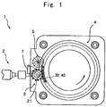
- Fig. 1 is a plan view schematically illustrating a molding system 1
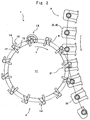
- Fig. 2 is a plan view illustrating, on an enlarged scale, part of the molding system of Fig. 1 .
- the molding system 1 is provided with an extruder 2, a synthetic resin feeder 3, a compression-molding apparatus 4 and a discharging device 5.
- the extruder 2 has nearly a cylindrical outer shape, and works to heat, melt and knead a synthetic resin material such as PP, PET or the like to form a synthetic resin.
- the extruder 2 includes, at an end thereof, an extrusion nozzle 7 that is mounted to freely turn over preset angles between a non-acting position represented by a solid line and an acting position represented by a two-dot chain line.
- the extrusion nozzle 7 is forming, in the lower surface at an end thereof, a resin flow passage extending up to an extrusion opening 20 shown in A and B of Fig. 11 .
- the extruder 2 continuously feeds a molten synthetic resin 8 to the extrusion nozzle 7; i.e., the synthetic resin 8 fed from the extruder 2 is extruded through the extrusion opening 20.
- the extrusion nozzle 7 is disposed at the acting position in the stand-by state represented by chain double-dashed line in Fig. 1 .
- the synthetic resin feeder 3 includes a rotary disk 11 that rotates in a direction indicated by an arrow a.
- a plurality of synthetic resin material introduction means 14 are arranged along the circumferential edge of the rotary disk 11 maintaining an equal distance in the circumferential direction.
- the synthetic resin material introduction means 14 are conveyed through a circular conveyer passage extending along the circumferential edge of the rotary disk 11, and are conveyed through a receiving zone 18 positioned just under the extrusion opening 20 of the extrusion nozzle 7 facing thereto and through a resin feed zone 21 positioned over a predetermined portion (molten resin-placing portion or recessed portion of a female mold or a male mold) of the compression-molding apparatus 4 facing thereto.
- each introduction means 14 has a cutter 17, a first holding member 15 and a second holding member 16.
- the first holding member 15 and the second holding member 16 in cooperation together, define a receiving space having a front surface in the direction of motion as well as an upper surface and a lower surface that are opened.
- the second holding member 16 is allowed to suitably move between an open position where it is separated away from the first holding member 15 as shown in Fig. 3A and a holding position where it approaches the first holding member 15 as shown in Fig. 3B .
- the cutter 17 is extending over the receiving space in a transverse direction.
- the synthetic resin material introduction means 14 passes through the receiving zone 18, the second holding member 16 is at the open position as shown in Fig. 3A , and the synthetic resin 8 of a molten state extruded from the extrusion opening 20 of the extrusion nozzle 7 is received in the receiving space.
- the cutter 17 moves with its upper surface in contact with, or close, to the lower surface of the extrusion nozzle 7, and cuts the synthetic resin 8 extruded from the extrusion opening 20 in cooperation with the lower surface of the extrusion nozzle 7.
- the second holding member 16 moves to a holding position as shown in Fig. 3B whereby the synthetic resin 8 cut from the extrusion opening 20 is held between the first holding member 15 and the second holding member 16.
- the second holding member 16 moves to an open position where the synthetic resin 8 starts liberated from being held by the first holding member 15 and the second holding member 16; i.e., the synthetic resin falls down onto a female mold 31 shown in Fig. 6 of the compression-molding machine located on the lower side.
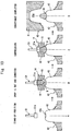
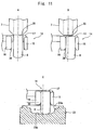
- Fig. 4 illustrates a metal mold 40 according to the first aspect of the invention, including a male mold 42 and a female mold 41.
- the male mold 42 is arranged as the lower mold and the female mold 41 is arranged as the upper mold.
- the male mold 42 has a punch body 43 protruding upward at a central portion of the main body thereof.
- a recessed portion 43a is formed in an upper part of the punch body 43 so as to be dented downward in an arcuate shape, and the synthetic resin 8 is fed into the recessed portion 43a.
- the female mold 41 is forming a cavity 41a in the center thereof, an opening portion thereof being arranged facing downward.
- the female mold 41 is provided with lift means that is not shown, and can be moved up and down relative to the male mold 42. If the female mold 41 moves down, the punch body 43 is inserted therein.
- a gas jet nozzle 37 is disposed over a portion where the synthetic resin 8 is held by the first holding member 15 and the second holding member 16 of the synthetic resin material intoduction means 14, and gas feed means that is not shown is connected to the jet nozzle 37.
- the jet nozzle 37 jets a compressed gas such as of an inert gas or the air.
- a flaring portion 38 that is flaring downward is formed at lower portions of the first holding member 15 and the second holding member 16.
- the extruder 2 heats, melts and kneads the synthetic resin material such as polypropylene, polyethylene terephthalate or the like, and conveys the synthetic resin 8 to the extrusion nozzle 7.
- the synthetic resin 8 extruded from the extrusion opening 20 of the extrusion nozzle 7 is cut by the cutter 17 and is separated away from the extrusion opening 20.
- the first and second holding members 15 and 16 are closed to hold the synthetic resin 8.
- the molten resin 8 held by the synthetic resin material inroduction means 14 of the closed state is disposed over the punch body 43 of male mold 42 of the compression-molding apparatus 4. When their tracks are moved onto the resin feed zone 21 (see Fig.
- the first and second holding members 15 and 16 of the synthetic resin material introduction means 14 are opened, whereby the synthetic resin 8 falls down onto the recessed portion 43a of the punch body 43 from the synthetic resin material introduction means 14 as shown in Fig. 5C .
- the male mold 42 is the lower mold, the distance which the synthetic resin 8 falls down is short, and the synthetic resin 8 can be disposed at a correct position in the recessed portion 43a.
- the compressed air is jetted from the jet nozzle 37 onto any portion of the synthetic resin 8; i.e., the compressed air adjusts the shape of the synthetic resin 8 and determines the position of the synthetic resin 8.
- the synthetic resin 8 is pre-molded, for example, in a direction in which the synthetic resin 8 is to be expanded at the time of being compressed (e.g., in a direction in which the molten resin expands less if there is any such a direction).
- pre-molding the synthetic resin 8 is not interrupted since the flaring portion 38 has been formed in the lower portions of the first and second holding members 15 and 16.
- the compressed air is jetted from the jet nozzle 37 to any portion of the synthetic resin 8. Therefore, the synthetic resin 8 is adjusted for its shape and is so held as to adhere to the recessed portion 43a of the punch body 43 preventing the deviation in position thereof.
- the introduction means 14 separates away from the metal mold 40 as shown in Fig. 5D .
- the synthetic resin 8 is premolded into a shape that can be easily compression-molded without deviation in position attaining good directivity for the compression-molding, and can be evenly expanded circumferentially.
- the container (or lid, preform, etc.) that is compression-molded is taken out from the metal mold 40 after cooled.
- a layer (one kind) of molten resin is used as the synthetic resin 8.
- synthetic resins of two or more layers comprising a central core layer and shell layers around the core layer (see patent document 1) may be compression-molded by the same apparatus as that of this embodiment.
- the synthetic resins of two or more layers comprising, for example, an inner layer having excellent gas-barrier property wrapped in outer layers having excellent mechanical properties and hygienic property, arouses a serious problem in that the synthetic resins that deviate in the female mold make it difficult to evenly expand the core layer of synthetic resin.
- This embodiment offers a favorable effect in compression-molding synthetic resins of a multi-layer structure, too.
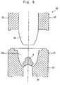
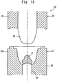
- Fig. 6 illustrates the metal mold 30 according to the second aspect.
- the metal mold 30 is constituted by a female mold 31 and a male mold 32, the female mold 31 having a female mold body 33 and a moving rod 34.
- the female mold 31 includes the moving rod 34 of a cylindrical shape which is the center member and the female mold body 33 surrounding the moving rod 34.
- the female mold body 33 forms a recessed portion 33c that is opened upward.
- the moving rod 34 has a placing surface 34a which forms a cavity 33a shown in Fig. 6 and Fig. 7D in cooperation with the recessed portion 33c of the female mold body 33.
- the moving rod 34 moves up and down between a normal position (lowered position) shown in Fig. 7D and an elevated position shown in Fig. 7A that has moved upward above the normal position.
- An upper end of the moving rod 34 is forming a placing surface 34a of an upwardly protruding mild arcuate shape for placing the synthetic resin 8 thereon.
- the male mold 32 includes a male mold body 35 and a core mold 36 arranged in the central portion of the male mold body 35.
- the male mold 32 can be slid up and down by drive means that is not shown.
- the gas jet nozzle 37 is arranged over a portion for holding the synthetic resin 8 that is formed by the first holding member 15 and the second holding member 16 for holding the synthetic resin 8 of the synthetic resin material introduction means 14, and gas feed means that is not shown is connected to the jet nozzle 37.
- the jet nozzle 37 jets a compressed gas such as of an inert gas or the air.
- a flaring portion 38 that is flaring downward is formed at lower portions of the first holding member 15 and the second holding member 16.
- the extruder 2 heats, melts and kneads the synthetic resin material such as polypropylene, polyethylene terephthalate or the like, and conveys the synthetic resin 8 to the extrusion nozzle 7.
- the synthetic resin 8 extruded from the extrusion opening 20 of the extrusion nozzle 7 is cut by the cutter 17 and is separated away from the extrusion opening 20.
- the first and second holding members 15 and 16 are closed to hold the synthetic resin 8.
- the molten resin 8 held by the synthetic resin material introduction means 14 of the closed state is moved so as to be positioned over the female mold 31 of the compression-molding apparatus 4.
- the moving rod 34 is disposed in a stand-by state at the elevated position.
- the synthetic resin material introduction means 14 has moved to the resin feed zone 21 (see Fig. 2 ) on the same track as that of the female mold 31 of the compression-molding apparatus 4, the introduction means 14 is positioned over the female mold 31 as shown in Fig. 7B .
- the placing surface 34a of the moving rod 34 for placing the synthetic resin 8 is disposed at a position close to the synthetic resin 8.
- the first and second holding members 15 and 16 of the synthetic resin material introduction means 14 are opened so that the synthetic resin 8 falls down onto the placing surface 34a of the moving rod 34 from the introduction means 14 as shown in Fig. 7C .
- the compressed air is jetted from the jet nozzle 37 onto any portion of the synthetic resin 8 to adjust the shape of the synthetic resin 8 and to determine the position of the synthetic resin 8.
- the synthetic resin 8 is pre-molded, for example, in a direction in which the synthetic resin 8 is to be expanded at the time of being compressed (e.g., in a direction in which the molten resin expands less if there is any such a direction).
- pre-molding the synthetic resin 8 is not interrupted since the flaring portion 38 has been formed in the lower portions of the first and second holding members 15 and 16.
- the synthetic resin material intoduction means 14 separates away from over the track of the metal mold 30, and the moving rod 34 moves together with the synthetic resin 8 down to the lowered position.
- the synthetic resin 8 is adjusted for its shape and is so held as to adhere onto the placing surface 34a on the moving rod 34. Therefore, deviation in position of the synthetic resin 8 can be prevented. Further, since the distance which the synthetic resin 8 falls down is short, the synthetic resin 8 can be disposed at a correct position.
- the male mold 32 moves down, and is overlapped on the female mold 31 whereby the core mold 36 moves down together with the male mold 32 to compress the synthetic resin 8.
- the container is compression-molded.
- the synthetic resin 8 is pre-molded into a shape that can be easily compression-molded without deviation in position attaining good directivity for the compression-molding, and can be evenly expanded circumferentially.
- the container (or lid, preform, etc.) that is compression-molded is taken out from the metal mold 30 after cooled.
- a layer (one kind) of molten resin is used as the synthetic resin 8.
- synthetic resins of two or more layers comprising a central core layer and shell layers around the core layer (see patent document 1) may be compression-molded by the same apparatus as that of this aspect.
- the synthetic resins of two or more layers comprising, for example, an inner layer having excellent gas-barrier property wrapped in outer layers having excellent mechanical properties and hygienic property, arouses a serious problem in that the synthetic resins that deviate in the female mold make it difficult to evenly expand the core layer of synthetic resin.
- This aspect offers a favorable effect in compression-molding synthetic resins of a multi-layer structure, too. Though this is not described below again, the same also holds in the embodiments described below.
- This embodiment uses the same metal mold as the metal mold 30 (see Fig. 6 ) described in the above second aspect, but what makes a difference is that the synthetic resin material introduction means 14 is not provided with the jet nozzle 37 and the metal mold is provided with a lift rod 51.
- the female mold 31 includes the female mold body 33 and the moving rod 34.
- the female mold body 33 forms a cavity 33a on the upper side in the central portion thereof (see Fig. 8D ) and a slide hole 33b communicated with the lower port of the cavity 33a.
- the moving rod 34 of a cylindrical shape is allowed to move up and down in the slide hole 33b being driven by drive means, and can be brought to an upper position shown in Fig. 8A and to a lower position shown in Fig. 8D .
- the upper end of the moving rod 34 is forming the placing surface 34a formed in an upwardly protruding mild arcuate shape for placing the synthetic resin 8 thereon.
- the lift rod 51 having an axis in the up-and-down direction is disposed over the female mold 31, and a pusher 51a is attached to an end (lower end) of the lift rod 51 to push the synthetic resin 8 toward the female mold 31.
- the lift rod 51 can be moved up and down, and is so disposed that the pusher 51a faces the placing surface 34a of the moving rod 34.
- the lift rod 51 and the moving rod 34 have their axes in agreement on a straight line. Referring to Fig. 8B , when the introduction means 14 and the female mold 31 have their tracks brought into agreement with each other, the introduction means
- the pusher 51a of the lift rod 51 is so constituted as to pass through the holding portion of the synthetic resin material introduction means 14 for holding the synthetic resin 8.
- Fig. 9 illustrates the shapes of the pusher, wherein the pusher 51a shown in Fig. 9A has a flat surface at the end thereof, the pusher 51b shown in Fig. 9B has a protruded spherical shape at the end thereof, and the pusher 51c shown in Fig. 9C has a recessed spherical shape at the end thereof, suitably differing depending upon the shape of the molded article.
- the lift rod 51 may be attached to the synthetic resin material introduction means 14.
- the lift rod 51 is disposed at the elevated position with the moving rod 34 standing by at its elevated position.
- the synthetic resin material introduction means 14 is positioned over the female mold 31 as shown in Fig. 8B
- the placing surface 34a of the moving rod 34 for placing the synthetic resin 8 is disposed at a position close to the synthetic resin 8.
- the first and second holding members 15 and 16 are opened permitting the synthetic resin 8 to fall down onto the placing surface 34a of the moving rod 34.
- the lift rod 51 moves down, enters into the first and second holding members 15 and 16, and pre-molds the synthetic resin 8 depending upon the shape of the end surface of the pusher 51a.
- the synthetic resin 8 is pre-molded in a direction in which the synthetic resin 8 is to be expanded at the time of compression-molding (in a direction in which the molten resin expands less if there is any such a direction).
- pre-molding the synthetic resin 8 is not interrupted since the flaring portion 38 has been formed in the lower portions of the first and second holding members 15 and 16.
- the lift rod 51 returns back to the elevated position
- the synthetic resin material introduction mens 14 separates away from above the female mold 31 as shown in Fig. 8D
- the moving rod 34 moves together with the synthetic resin 8 down to the lowered position.
- the synthetic resin 8 is adjusted for its shape and is so held as to adhere onto the placing surface 34a on the moving rod 34. Therefore, deviation in position of the synthetic resin 8 can be prevented. Further, since the distance which the synthetic resin 8 falls down is short, the synthetic resin 8 can be disposed at a correct position.
- the male mold 32 moves down and is overlapped on the female mold 31 whereby the core mold 36 moves down to compress the synthetic resin 8.
- the container is molded.
- the synthetic resin 8 is pre-molded into a shape that can be easily compression-molded without deviation in position attaining good directivity for the compression-molding, and can be evenly expanded circumferentially.
- the container (or lid, preform, etc.) that is compression-molded is taken out from the metal mold 30 after cooled.
- the lift rod 51 of the above embodiment is used instead of the jet nozzle 37 of the above first embodiment.
- the metal mold 40 has the male mold 42 arranged as the lower mold and the female mold 41 arranged as the upper mold.
- the male mold 42 has, in the center portion thereof, a punch body 43 protruding upward, and a recessed portion 43a is formed in the upper part of the punch body 43 dented downward.
- the female mold 41 is forming a cavity 41a in the center thereof.
- the lift rod 51 having an axis in the up-and-down direction is disposed over the male mold 42, and the pusher 51a is attached to the end (lower end) of the lift rod 51 to push the synthetic resin 8 toward the male mold.
- the lift rod 51 can be moved up and down, and is so disposed that the pusher 51a faces the recessed portion 43a of the punch body 43.
- the introduction means 14 can be disposed between the lift rod 51 and the male mold 42.
- the pusher 51a of the lift rod 51 is so constituted as to pass through the holding portion of the synthetic resin material introduction means 14 for holding the synthetic resin 8.
- the lift rod 51 moves down, enters into the first and second holding members 15 and 16, and pushes the synthetic resin 8 onto the recessed portion 43a of the punch body 43.
- the synthetic resin 8 can be pre-molded depending upon the shape of the end surface of the pusher 51a of the lift rod 51.
- pre-molding the synthetic resin 8 is not interrupted since the flaring portion 38 has been formed in the lower portions of the first and second holding members 15 and 16.
- the lift rod 51 returns back to the elevated position, and the synthetic resin material introduction means 14 and the lift rod 51 separate away from above the track of the male mold 42 as shown in Fig. 10D .
- the synthetic resin 8 is adjusted for its shape and is so held as to adhere onto the recessed portion 43a of the punch body 43. Therefore, deviation in position of the synthetic resin 8 can be prevented. Further, since the distance which the synthetic resin 8 falls down is short, the synthetic resin 8 can be disposed at a correct position.
- the female mold 41 moves down and is overlapped on the male mold 42 whereby the synthetic resin 8 is compressed to mold a container.
- the synthetic resin 8 is pre-molded into a shape that can be easily compression-molded without deviation in position attaining good directivity for the compression-molding, and can be evenly expanded circumferentially.
- the container (or lid, preform, etc.) that is compression-molded is taken out from the metal mold 40 after cooled.
- the synthetic resin material introduction means 14 has a shape different from that of the above first and second aspects but is described by attaching the same reference numeral for convenience.
- each of the synthetic resin material introduction means 14 has the cutter 17, first holding member 15 and second holding member 16.
- the first holding member 15 and the second holding member 16 work in cooperation to define a receiving space having a front surface in the moving direction, an upper surface and a lower surface, which are opening.
- the second holding member 16 is allowed to suitably move between an open position where it separates away from the first holding member 15 as shown in Fig. 11A and a holding position where it approaches the first holding member 15 as shown in Fig. 11B .
- the holding members 15 and 16 have a length in the up-and-down direction which is shorter than the length of a unit (bullet) of the synthetic resin 8 that is extruded downward from the extrusion nozzle 7 and is cut by the cutter 17. That is, while the holding members 15 and 16 are holding the synthetic resin 8, the lower end of the synthetic resin 8 is allowed to protrude beyond the lower end of the holding members 15 and 16 (see Fig. 22A which is a plan view of the holding members 15 and 16).
- the cutter 17 for cutting the synthetic resin 8 is extending sideways above the receiving space of the holding members 15 and 16. Just before the introduction means 14 passes through the receiving zone 18, the second holding member 16 is at the open position as shown in Fig. 11A , and the synthetic resin 8 in the molten state extruded from the extrusion opening 20 of the extrusion nozzle 7 is received by the receiving space.
- the cutter 17 moves with its upper surface in contact with, or close to, the lower surface of the extrusion nozzle 7, and cuts the synthetic resin 8 extruded from the extrusion opening 20 in cooperation with the lower surface of the extrusion nozzle 7.
- the second holding member 16 moves to the holding position as shown in Fig. 11B .
- the synthetic resin 8 cut from the extrusion opening 20 is held between the first holding member 15 and the second holding member 16.
- Fig. 12 illustrates a metal mold 22 according to the third aspect of the invention.
- the metal mold 22 is constituted by a female mold 23 and a male mold 24, the female mold 23 forming, in the central portion thereof, a recessed portion 23a that is opened upward, and the recessed portion 23a forming, in the bottom portion thereof, a placing surface 23b for placing the synthetic resin 8.
- the male mold 24 includes a male mold body 25 and a core mold 26 disposed in the central hole of the male mold body 25.
- the male mold 24 can be moved up and down by drive means that is not shown.
- the extruder 2 shown in Fig. 1 heats, melts and kneads the synthetic resin material such as polypropylene, polyethylene terephthalate or the like, and conveys the synthetic resin 8 to the extrusion nozzle 7.
- the synthetic resin 8 extruded from the extrusion opening 20 of the extrusion nozzle 7 is cut by the cutter 17 and is separated away from the extrusion opening 20.
- the first and second holding members 15 and 16 are closed to hold the synthetic resin 8.
- the holding members 15 and 16 so hold the synthetic resin 8 that the lower end thereof protrudes downward beyond the holding members 15 and 16.
- the synthetic resin 8 held by the synthetic resin material introduction means 14 is moved to the female mold 23 of the compression-molding apparatus 4.
- the holding members 15 and 16 work to position the synthetic resin 8 over the female mold 23.
- the synthetic resin material introduction means 14 causes the holding members 15 and 16 to move down toward the female mold 23 by using lift means that is not shown.
- the holding members 15 and 16 work to bring the lower end of the synthetic resin 8 into contact with a predetermined position on the placing surface 23b of the female mold 23 on which the synthetic resin 8 is to be placed, and to position the synthetic resin 8 on the placing surface 23b so as to push or crush the lower end of the synthetic resin 8 even after the synthetic resin 8 has come in contact. Therefore, the lower end of the synthetic resin 8 must have been protruded beyond the lower ends of the holding members 15 and 16 to a sufficient degree so that the holding members 15 and 16 will not come in contact with the female mold 23.
- the synthetic resin material introduction means 14 moves up with the first and second holding members 15 and 16 of the synthetic resin material introduction means 14 in the open state. Thereafter, the synthetic resin material introduction means 14 separates away from over the track of the metal mold 22. At this moment, the compressed air is jetted from the jet nozzle 37 (see Fig. 14C ) onto any portion of the synthetic resin 8, or the synthetic resin 8 may be pre-molded depending upon the shape of the end surface of the pusher 51a (see Fig. 16C ) to adjust the shape of the synthetic resin 8 as described in the embodiments below. In this case, pre-molding the synthetic resin 8 is not interrupted since the flaring portion 38 has been formed in the lower portions of the first and second holding members 15 and 16.
- the male mold 24 shown in Fig. 12 moves down and is overlapped on the female mold 23 whereby the core mold 36 moves down together with the male mold 24 to compress the synthetic resin 8 to thereby compression-mold a container.
- the synthetic resin 8 is pre-molded into a shape that can be easily compression-molded without deviation in position attaining good directivity of the synthetic resin 8 for the compression-molding, and can be evenly expanded circumferentially.
- the preform (container, lid, etc.) that is compression-molded is taken out from the metal mold 22 after cooled.
- a layer (one kind) of molten resin is used as the synthetic resin 8.
- synthetic resins of two or more layers comprising a central core layer and shell layers around the core layer (see patent document 1) may be compression-molded by the same apparatus as that of this aspect.
- the synthetic resins of two or more layers comprising, for example, an inner layer having excellent gas-barrier property wrapped in outer layers having excellent mechanical properties and hygienic property, arouse a serious problem in that the synthetic resins that deviate in the female mold make it difficult to evenly expand the core layer of synthetic resin.
- This aspect offers a favorable effect in compression-molding synthetic resins of a multi-layer structure, too. The same also holds in other embodiments.
- Fig. 13 shows a metal mold 30 according to an embodiment of the second aspect the invention which is substantially the same as the metal mold of the above second aspect.
- the metal mold 30 is constituted by a female mold 31 and a male mold 32, the female mold 31 having a female mold body 33 and a moving rod 34.
- the female mold 31 includes a moving rod 34 of a cylindrical shape which is the center member and the female mold body 33 surrounding the moving rod 34.
- the female mold body 33 forms a recessed portion 33c that is opened upward.
- the moving rod 34 has a placing surface 34a which forms a cavity 33a shown in Fig. 14D in cooperation with the recessed portion 33c of the female mold body 33.
- the moving rod 34 moves up and down between a normal position (lowered position) shown in Fig. 14D and an elevated position shown in Fig. 14A that has moved upward above the normal position.
- An upper end of the moving rod 34 is forming a placing surface 34a of an upwardly protruding mild arcuate shape for placing the synthetic resin 8 thereon.
- the male mold 32 includes a male mold body 35 and a core mold 36 arranged in the central portion of the male mold body 35.
- the male mold 32 can be moved up and down by drive means that is not shown.
- the first holding member 15 and the second holding member 16 of the introduction means 14 for holding the synthetic resin 8 are constituted in the same manner as those of the above third aspect.
- the holding members 15 and 16 have a length in the up-and-down direction which is shorter than the length of a unit (bullet) of the synthetic resin 8 that is extruded from the extrusion nozzle 7 and is cut by the cutter 17. While the holding members 15 and 16 are holding the synthetic resin 8, the lower end of the synthetic resin 8 is allowed to protrude beyond the lower ends of the holding members 15 and 16.
- a gas jet nozzle 37 is arranged over a portion for holding the synthetic resin 8 that is formed by the first holding member 15 and the second holding member 16, and gas feed means that is not shown is connected to the jet nozzle 37.
- the jet nozzle 37 jets a compressed gas such as of an inert gas or the air.
- a flaring portion 38 that is flaring downward is formed at lower portions of the first holding member 15 and the second holding member 16.
- the extruder 2 heats, melts and kneads the synthetic resin material such as polypropylene, polyethylene terephthalate or the like, and conveys the synthetic resin 8 to the extrusion nozzle 7.
- the synthetic resin 8 extruded from the extrusion opening 20 of the extrusion nozzle 7 is cut by the cutter 17 and is separated away from the extrusion opening 20.
- the first and second holding members 15 and 16 are closed to hold the synthetic resin 8.
- holding members 15 and 16 so hold the synthetic resin 8 that the lower end thereof protrudes downward beyond the holding members 15 and 16.
- the molten resin 8 held by the synthetic resin material introduction means 14 of the closed state is moved so as to be positioned over the female mold 31 of the compression-molding apparatus 4.
- the moving rod 34 is disposed in a stand-by state at the elevated position.
- the synthetic resin material introduction means 14 has moved to the resin feed zone 21 (see Fig. 2 ) on the same track as that of the female mold 31 of the compression-molding apparatus 4, the synthetic resin material introduction means 14 is positioned over the moving rod 34 of the female mold 31 as shown in Fig. 14B .
- the.placing surface 34a of the moving rod 34 for placing the synthetic resin 8 is disposed at a position close to the synthetic resin 8.
- the first and second holding members 15 and 16 of the synthetic resin material introduction means 14 are moved down by lift means that is not shown; i.e., the support members 15 and 16 move down toward the female mold 31.
- the holding members 15 and 16 work to bring the lower end of the synthetic resin 8 into contact with a predetermined position on the placing surface 34a of the moving rod 34 of the female mold 31 on which the synthetic resin 8 is to be placed, and to position the synthetic resin on the placing surface 34a so as to press or crush the synthetic resin 8 onto the lower end side even after having come in contact.
- the holding members 15 and 16 are opened to release the synthetic resin 8 and, thereafter, the holding members 15 and 16 are moved up. Thereafter, the synthetic resin material introduction means 14 separates away from over the track of the metal mold 22.
- the compressed air is jetted from the jet nozzle 37 onto any portion of the synthetic resin 8 to adjust the shape of the synthetic resin 8 and to determine the position of the synthetic resin 8.
- the synthetic resin 8 is pre-molded, for example, in a direction in which the synthetic resin 8 is to be expanded at the time of being compressed (e.g., in a direction in which the molten resin expands less if there is any such a direction).
- pre-molding the synthetic resin 8 is not interrupted since the flaring portion 38 has been formed in the lower portions of the first and second holding members 15 and 16.
- the introduction means 14 separates away from over the track of the metal mold 30, and the moving rod 34 moves together with the synthetic resin 8 down to the lowered position.
- the synthetic resin 8 is adjusted for its shape and is so held as to adhere onto the placing surface 34a of the moving rod 34. Therefore, deviation in position of the synthetic resin 8 can be prevented.
- the male mold 32 moves down, and is overlapped on the female mold 31 whereby the core mold 36 moves down together with the male mold 32 to compress the synthetic resin 8.
- the preform (container, lid, etc.) is compression-molded.
- the synthetic resin 8 is pre-molded into a shape that can be easily compression-molded without deviation in position attaining good directivity for the compression-molding, and can be evenly expanded circumferentially.
- the preform or the like that is compression-molded is taken out from the metal mold 30 after cooled.
- the above third aspect is capable of forming a container having a deep bottom if, for example, the holding members 15 and 16 are of such a mechanism that enters into the recessed portion 23b of the female mold 23 but is not suited for forming a container having a deep bottom if the holding members 15 and 16 interfere with the recessed portion 23b.
- the moving rod 34 moves up to meet the synthetic resin 8 without causing interference offering an effect that the embodiment can be applied unconditionally to the containers having a deep bottom.
- This embodiment is different from the above embodiment of the third aspect with regard to the metal mold only.
- the metal mold is substantially the same as the metal mold of the first aspect.
- the metal mold 40 of Fig. 15 has the male mold 42 arranged as the lower mold and the female mold 41 arranged as the upper mold.
- the male mold 42 has a punch body 43 protruding upward at a central portion thereof.
- a recessed portion 43a is formed in an upper part of the punch body 43 so as to be dented downward in an arcuate shape to place the synthetic resin 8 thereon.
- the female mold 41 is forming a cavity 41a that is opening facing downward in the center thereof.
- the first holding member 15 and the second holding member 16 of the synthetic resin material introduction means 14 for holding the synthetic resin 8 are constituted in the same manner as those of the above embodiment of the third aspect, and have a length in the up-and-down direction which is shorter than the length of a unit of the synthetic resin 8 that is extruded from the extrusion nozzle 7 and is cut by the cutter 17. Referring to Fig. 15B , while the holding members 15 and 16 are holding the synthetic resin 8, the lower end of the synthetic resin 8 is allowed to protrude downward beyond the lower end of the holding members 15 and 16.
- the synthetic resin 8 extruded from the extrusion nozzle 7 is cut by the cutter 17 (see Fig. 11 ).
- the holding members 15 and 16 hold the synthetic resin 8 in a manner that the lower end thereof protrudes downward beyond the holding members 15 and 16.
- the synthetic resin material introduction means 14 is conveyed to over the punch body 43 of the male mold 42 which is in the stand-by state as shown in Fig. 15B , the synthetic resin 8 is disposed at a position close to the recessed portion 43a of the punch body 43.
- their tracks are moved onto the resin feed zone 21 (see Fig.
- the first and second holding members 15 and 16 of the synthetic resin material introduction means 14 are moved down by lift means which is not shown; i.e., the holding members 15 and 16 move down ward the male mold.
- the holding members 15 and 16 work to bring the lower end of the synthetic resin 8 into contact with a predetermined position of the recessed portion 43a which is the placing surface of the punch body 43 for placing the synthetic resin 8, and to position the synthetic resin 8 on the recessed portion 43a so as to press or crush the synthetic resin 8 onto the lower end side even after having come in contact.
- the holding members 15 and 16 are opened to release the synthetic resin 8 and, thereafter, the holding members 15 and 16 are moved up. Thereafter, the synthetic resin material introduction means 14 separates away from over the track of the metal mold 40.
- the compressed air is jetted from the jet nozzle 37 onto any portion of the synthetic resin 8 to adjust the shape of the synthetic resin 8 so as to be held being adhered to the recessed portion 43a of the punch body 43 preventing deviation in position.
- the synthetic resin 8 is pre-molded in a shape that can be easily compression-molded without deviation in position attaining good directivity for the compression-molding, and can be evenly expanded circumferentially.
- the container (or lid, preform, etc.) that is compression-molded is taken out from the metal mold 40 after cooled.
- the above third aspect requires a contrivance for compression-molding a container having a deep bottom as described above. According to this embodiment of the first aspect, however, the punch body 43 of the male mold 42 does not interfere with the holding members 15 and 16 offering an effect that the embodiment can be applied unconditionally to the containers having a deep bottom.
- This embodiment uses the same metal mold as the metal mold 30 (see Fig. 13 ) described in the above embodiment of the second aspect, but what makes a difference is that the synthetic resin material introduction means 14 is not provided with the jet nozzle 37 and the metal mold is provided with a lift rod 51.
- the female mold 31 includes the female mold body 33 and the moving rod 34.
- the female mold body 33 forms a cavity 33a on the upper side in the central portion thereof (see Fig. 16D ) and a slide hole 33b communicated with the lower part of the cavity 33a.
- the moving rod 34 of a cylindrical shape is allowed to move up and down in the slide hole 33b being driven by drive means, and can be brought to an upper position shown in Fig. 16A and to a lower position shown in Fig. 16D .
- the upper end of the moving rod 34 is forming the placing surface 34a formed in an upwardly protruding mild arcuate shape for placing the synthetic resin 8 thereon.
- the first holding member 15 and the second holding member 16 of the introduction means 14 for holding the synthetic resin 8 are constituted in the same manner as those of the above third aspect, have a length in the up-and-down direction which is shorter than the length of a unit of the synthetic resin 8 that is extruded from the extrusion nozzle 7 and is cut by the cutter 17 so that when the holding members 15 and 16 are holding the synthetic resin 8, the lower end of the synthetic resin 8 is allowed to protrude downward beyond the lower end of the holding members 15 and 16.
- the lift rod 51 having an axis in the up-and-down direction is disposed over the female mold 31, and a pusher 51a is attached to an end (lower end) of the lift rod 51 to push the synthetic resin 8 toward the female mold.
- the lift rod 51 can be moved up and down, and is so disposed that the pusher 51a faces the placing surface 34a of the moving rod 34.
- the lift rod 51 and the moving rod 34 have their axes in agreement on a straight line.
- the introduction means 14 and the female mold 31 have their tracks brought into agreement with each other, and the synthetic resin material introduction means 14 is disposed between the lift rod 51 and the female mold 31.
- the pusher 51a of the lift rod 51 is so constituted as to pass through the holding portion of the synthetic resin material introduction means 14 for holding the synthetic resin 8.
- Fig. 9 illustrates the shapes of the pusher 51, wherein the pusher shown in Fig. 9A has a flat surface at the end thereof, the pusher 51b shown in Fig. 9B has a protruded spherical shape at the end thereof, and the pusher 51c shown in Fig. 9C has a recessed spherical shape at the end thereof, suitably differing depending upon the shape of the molded article.
- the lift rod 51 may be attached to the synthetic resin material introduction means 14.
- the holding members 15 and 16 hold the synthetic resin 8 in a manner that the lower end thereof protrudes downward beyond the holding members 15 and 16 as shown in Fig. 16B .
- the lift rod 51 is disposed at the elevated position with the moving rod 34 in the stand-by state at the elevated position.
- the introduction means 14 is positioned over the female mold 31 of the compression-molding apparatus 4, the placing surface 34a of the moving rod 34 for placing the synthetic resin 8 is disposed just over the synthetic resin 8 as shown in Fig. 16B .
- the holding members 15 and 16 of the synthetic resin material introduction means 14 are moved down by lift means that is not shown; i.e.
- the holding members 15 and 16 move down toward the female mold 31.
- the holding members 15 and 16 work to bring the lower end of the synthetic resin 8 into contact with a predetermined position on the placing surface 34 of the moving rod 34 of the female mold 31 on which the synthetic resin 8 is to be placed, and to position the synthetic resin 8 on the placing surface 34a so as to press or crush the synthetic resin 8 onto the lower end side even after having come in contact.
- the lift rod 51 moves down, enters into the first and second holding members 15 and 16, and pre-molds the synthetic resin 8 depending upon the shape of the end surface of the pusher 51a.
- the synthetic resin 8 is pre-molded in a direction in which the synthetic resin 8 is to be expanded at the time of compression-molding (in a direction in which the molten resin expands less if there is any such a direction or in a direction in which the thickness must be increased if dissimilar shapes are included).
- varying the shape of the synthetic resin 8 is not interrupted since the flaring portion 38 has been formed in the lower portions of the first and second holding members 15 and 16.
- the holding members 15 and 16 are opened to release the synthetic resin 8 and, thereafter, the holding members 15 and 16 are moved up. Thereafter, the synthetic resin material introduction means 14 separates away from over the track of the metal mold 32.
- the lift rod 51 returns back to the elevated position
- the synthetic resin material introduction means 14 separates away from over the female mold 31 as shown in Fig. 16D
- the moving rod 34 moves together with the synthetic resin 8 down to the lowered position.
- the synthetic resin 8 is adjusted for its shape and is so held as to adhere to the placing surface 34a of the moving rod 34. Therefore, the synthetic resin 8 is prevented from deviating in position and is disposed on the placing surface 34a at a correct position.
- the male mold 32 moves down and is overlapped on the female mold 31 whereby the core mold 36 moves down to compress the synthetic resin 8 and, therefore, to mold the container.
- the synthetic resin 8 is pre-molded into a shape that can be easily compression-molded without deviation in position attaining good directivity for the compression-molding, and can be evenly expanded circumferentially.
- the container (or preform or the like) that is compression-molded is taken out from the metal mold 30 after cooled.
- the above third aspect requires a contrivance for compression-molding a container having a deep bottom, as described above. According to the embodiment, according to Fig. 16 , however, the moving rod 34 moves up to meet the synthetic resin 8 offering an effect that the embodiment can be applied unconditionally to the containers having a deep bottom.
- the male mold is arranged as the lower mold and the lift rod 51 of the above embodiments is used instead of the jet nozzle 37 of the above embodiment.
- the male mold 42 has, in the center portion thereof, a punch body 43 protruding upward, and a recessed portion 43a is formed in the upper part of the punch body 43 so as to be dented downward.
- the female mold 41 is forming a cavity 41a in the center thereof.
- the holding members 15 and 16 have a length in the up-and-down direction which is shorter than the length of a unit of the synthetic resin 8 that is extruded from the extrusion nozzle 7 and is cut by the cutter 17. While the holding members 15 and 16 are holding the synthetic resin 8, the lower end of the synthetic resin 8 is allowed to protrude downward beyond the lower ends of the holding members 15 and 16.
- the lift rod 51 having an axis in the up-and-down direction is disposed over the male mold 42, and a pusher 51a is attached to an end (lower end) of the lift rod 51 to push the synthetic resin 8 toward the male mold.
- the lift rod 51 can be moved up and down, and is so disposed that the pusher 51a faces the recessed portion 43a of the punch body 43.
- the synthetic resin material introduction means 14 can be disposed between the lift rod 51 and the male mold 42.
- the pusher 51a of the lift rod 51 is so constituted as to pass through the holding portion of the introduction means 14 for holding the synthetic resin 8.
- the holding members 15 and 16 hold the synthetic resin 8 in a manner that the lower end thereof protrudes downward beyond the holding members 15 and 16 as shown in Fig. 17B .
- the synthetic resin material introduction means 14 is conveyed to over the punch body 43 of the male mold 42 which is in the stand-by state, the synthetic resin 8 is disposed at a position close to the recessed portion 43a of the punch body 43.
- their tracks are moved onto the resin feed zone 21 (see Fig. 2 )
- the first and second holding members 15 and 16 of the synthetic resin material introduction means 14 are moved down by lift means which is not shown; i.e., the holding members 15 and 16 move down toward the male mold.
- the holding members 15 and 16 work to bring the lower end of the synthetic resin 8 into contact with a predetermined,position of the recessed portion 43a which is the placing surface of the punch body 43 for placing the synthetic resin 8, and to position the synthetic resin 8 on the recessed portion 43a so as to press or crush the synthetic resin 8 onto the lower end side even after having come in contact.
- the lift rod 51 moves down, enters into the first and second holding members 15 and 16, and pushes the synthetic resin 8 onto the recessed portion 43a of the punch body 43.
- the synthetic resin 8 can be pre-molded depending upon the shape of the end surface of the pusher 51a of the lift rod 51.
- varying the shape of the synthetic resin 8 is not interrupted since the flaring portion 38 has been formed in the lower portions of the first and second holding members 15 and 16.
- the pusher 51a is moved up, the holding members 15 and 16 are opened to release the synthetic resin 8 and, thereafter, the holding members 15 and 16 are moved up. Thereafter, the synthetic resin material introduction means 14 separates away from over the track of the metal mold 40.
- the synthetic resin 8 is adjusted for its shape and is so held as to adhere to the recessed portion 43a of the punch body 43. Therefore, the synthetic resin 8 is prevented from deviating in position and is disposed at a correct position.
- the female mold 32 moves down and is overlapped on the male mold 42 to compress the synthetic resin 8 and, therefore, to mold the container.
- the synthetic resin 8 is pre-molded into a shape that can be easily compression-molded without deviation in position attaining good directivity for the compression-molding, and can be evenly expanded circumferentially.
- the container (or preform or the like) that is compression-molded is taken out from the metal mold 40 after cooled.
- the above third aspect requires a contrivance for compression-molding a container having a deep bottom as described above. According to the embodiment, according to Fig. 17 , however, the punch body 43 of the male mold 42 does not interfere with the holding members 15 and 16 offering an effect that the embodiment can be applied unconditionally to the containers having a deep bottom.
- Fig. 18 is a plan view schematically illustrating a molding system
- Fig. 19 is a plan view illustrating, on an enlarged scale, any one of a plurality of cutting/holding units 75 arranged about an extrusion nozzle 74 of an extruder 71 of the molding system 70.
- the molding system 70 includes the extruder 71 which melts and kneads the synthetic resin and extrudes it through the extrusion nozzle 74, the plurality of cutting/holding units 75 arranged about the extrusion nozzle 74 of the extruder 71, and a plurality of compression metal molds 40 arranged together with the cutting/holding units 75 in pairs.
- the extruder 71 is so provided that the extrusion nozzle 74 that is opened in a die head 76 thereof extrudes the resin in a molten state nearly downward along the vertical direction.
- the cutting/holding units 75 arranged about the extrusion nozzle 74 that extrudes the molten resin are mounted on a plurality of drive mechanisms 77 that are nearly radially installed about the extrusion nozzle 74, and move alternately and reciprocally between a position under the extrusion nozzle 74 and the feed positions set for the cutting/holding units 75.
- compression metal molds 40 are installed in pairs with the cutting/holding units 75.
- Fig. 20 is a view schematically illustrating the cutting/holding unit 75, wherein Fig. 20A is a plan view and Fig. 20B is a sectional view along Y-Y of Fig. 20A .
- the cutting/holding unit 75 has a cutter 81 for cutting the molten resin extruded from the extrusion nozzle 74 at the time when it passes under the extrusion nozzle 74 toward the compression metal mold 40 installed at the feed position.
- the cutter 81 is formed along the circumferential edge at the upper part of the holding member 82.
- the inner circumferential surface of the holding member 82 serves as a holding surface 84 and comes in contact with the side surface of the molten resin 8 that is cut by the cutter 81.
- the other holding member 83 On one holding member 82 of the cutting/holding member 75, the other holding member 83 is attached thereto facing the holding surface 84 so as to be opened and closed.
- the other holding member 83 is opened and closed about a rotary shaft 87 being driven by, for example, a rotary actuator or the like that is not shown.
- the other holding member 83 At the time when the cutting/holding unit 75 passes under the extrusion nozzle 74, the other holding member 83 is at its open position (two-dot chain lines in Fig. 20A ) so will not to hinder the molten resin from being cut by the cutter 81, and is closed (solid lines in Fig. 20A ) after the molten resin is cut.
- the molten resin extruded from the extrusion nozzle 74 must be cut into such a length that protrudes downward beyond the lower end of the holding surface 84.
- the molten resin 8 that is cut is held in a cylindrical space between the holding surface 84 and the holding member 83.
- the molten resin 8 can be fed into the mold 40 when the cutting/holding unit 75 comes into a halt at the feed position.
- the drive mechanism 77 shown in Fig. 19 includes a horizontal drive actuator 85 for reciprocally moving the cutting/holding unit 75 in a horizontal direction and a vertical drive actuator 86 for moving them up and down in a vertical direction.
- the vertical drive actuator 86 moves the cutting/holding unit 75 up and down along a guide support member (not shown) that extends in the vertical direction and supports the cutting/holding unit 75.
- the metal mold 40 of Fig. 21 has the male mold 42 arranged as the lower mold and the female mold 41 arranged as the upper mold as described in the above embodiments.
- the male mold 42 is provided with the punch body 43 protruding upward at the central portion thereof, and the recessed portion 43a is formed in the upper part of the punch body 43 in a downwardly dented arcuate shape for placing the synthetic resin 8.
- the female mold 41 is forming the cavity 41a that is open at the center thereof facing downward.
- the synthetic resin 8 extruded from the extrusion nozzle 74 is cut by the cutter 81, and the holding members 82 and 83 hold the synthetic resin 8 in a manner that the lower end thereof protrudes downward beyond the holding members 82 and 83 as shown in Fig. 16B .
- the cutting/holding unit 75 is conveyed to over the punch body 43 of the male mold 42 which is in the stand-by state as shown in Fig. 21B , the synthetic resin 8 is disposed at a position close to the recessed portion 43a.
- lift means equipped with the vertical drive actuator 86 of the cutting/holding unit 75 causes the holding members 82 and 83 to move down; i.e., the holding members 82 and 83 move down toward the male mold.
- the holding members 82 and 83 work to bring the lower end of the synthetic resin 8 into contact with the predetermined position of the recessed portion 43a which is the placing surface of the punch body 43 for placing the synthetic resin 8 and to position the synthetic resin 8 on the recessed portion 43a so as to push or crush the synthetic resin 8 toward the lower end side even after the synthetic resin 8 has come in contact.
- the holding members 82 and 83 are opened to release the synthetic resin 8. Thereafter, the holding members 82 and 83 are moved up. Then, the cutting/holding unit 75 separates away from the metal mold 40.
- the synthetic resin 8 is so held as to adhere to the recessed portion 43a of the punch body 43 preventing deviation in position. At the time of molding, there is no deviation in position attaining good directivity for the compression-molding, and the synthetic resin 8 can be evenly expanded circumferentially.
- the container (or lid, preform, etc.) that is compression-molded is taken out from the metal mold 40 after cooled.
- the compression-molding apparatus is not limited to the one having many synthetic resin material introduction means 14 and metal molds that rotate continuously but may be the one that takes one each time.
- the introduction means in the above embodiments may be replaced by those of the linear conveyance type described in the embodiment according to Fig. 19 , 20 .
- the introduction means 14 or the cutting/holding units 75 in the above embodiments are of the so-called three-split type (three parts) of which the holding members 15 and 16 (82 and 83) move back and forth in a horizontal direction.
- a cutting/holding unit 60 may be of the two-split type (two parts) in which a hinge 63 is formed at a portion connecting the holding members 61 and 62 so that either one of the holding member 61 or 62 turns to open or close.
Claims (7)
- Pressformvorrichtung, die umfasst: eine Vielzahl aufnehmender Formen (41) mit einem vertieften Formabschnitt, eine Vielzahl aufzunehmender Formen (42), die sich relativ zu der aufnehmenden Form (41) auf und ab bewegen und selektiv in eine geschlossene Position, in der sie in Zusammenwirkung mit der aufnehmenden Form (41) einen Formraum bilden, und in eine offene Position, in der sie von der aufnehmenden Form (41) beabstandet positioniert sind, gebracht werden, und eine Vielzahl von Kunstharzmaterialeinleitungsmitteln (14), die mit dessen Drehung ein Kunstharzmaterial (8) von einem Extruder (2) erhalten und die zwischen der aufnehmenden Form (41) und der aufzunehmenden Form (42) positioniert sind, wenn die aufzunehmende Form (42) in der offenen Position ist; wobei
die Kunstharzmaterialeinleitungsmittel (14) und die aufzunehmende Form (42) sich auf verschiedenen Spuren bewegen und ihre Spuren an einer Harzspeisungszone (21) in Übereinstimmung miteinander bringen,
wobei die Kunstharzmaterialeinleitungsmittel (14) zulassen, dass das Kunstharzmaterial (8), das sie halten, nach unten fällt, wenn beide Spuren der aufzunehmenden Form (42) und der Kunstharzmaterialeinleitungsmittel (14) sich zu der Harzspeisungszone (21) bewegt haben, während sie sich gegenseitig drehen; wobei
der vertiefte Formabschnitt der aufnehmenden Form (41) nach unten geöffnet ist, die aufzunehmende Form (42) unter der aufnehmenden Form (41) angeordnet ist und einen Stempelkörper (43) hat, der in einem mittleren Abschnitt ihres Hauptkörpers nach oben vorsteht, um die Fallstrecke zu den Einleitungsmitteln (14) zu verkürzen, und das Kunstharzmaterial (8) von den Kunstharzmaterialeinleitungsmitteln nach unten auf den Stempelkörper (43) fällt. - Pressformvorrichtung, die umfasst: eine Vielzahl aufnehmender Formen (31) mit einem vertieften Formabschnitt (33a), der nach oben geöffnet ist, eine Vielzahl aufzunehmender Formen (32), die über der aufnehmenden Form (31) angeordnet sind und sich relativ zu der aufnehmenden Form (31) auf und ab bewegen und selektiv in eine geschlossene Position, in der sie in Zusammenwirkung mit der aufnehmenden Form (31) einen Formraum bilden, und in eine offene Position, in der sie von der aufnehmenden Form (31) beabstandet positioniert sind, gebracht werden, und eine Vielzahl von Kunstharzmaterialeinleitungsmitteln (14), die mit dessen Drehung ein Kunstharzmaterial (8) von einem Extruder (2) erhalten und die zwischen der aufnehmenden Form (31) und der aufzunehmenden Form (32) positioniert sind, wenn die aufzunehmende Form (32) in der offenen Position ist; wobei
die Kunstharzmaterialeinleitungsmittel (14) und die aufnehmende Form (31) sich auf verschiedenen Spuren bewegen und ihre Spuren an einer Harzspeisungszone (21) in Übereinstimmung miteinander bringen,
wobei die Kunstharzmaterialeinleitungsmittel (14) zulassen, dass ein Kunstharzmaterial (8), das sie halten, nach unten fällt, wenn beide Spuren der aufnehmenden Form (31) und der Kunstharzmaterialeinleitungsmittel (14) sich zu der Harzspeisungszone (21) bewegt haben, während sie sich gegenseitig drehen; und
die aufnehmende Form (31) eine sich bewegende Stange (34) und ein Umfangselement (33), das die sich bewegende Stange (34) umgibt, umfasst, wobei das Umfangselement (33) einen vertieften Abschnitt (33a) bildet, der nach oben geöffnet ist, wobei die sich bewegende Stange (34) sich zwischen einer normalen Position, in der ihre obere Oberfläche (34a) in Zusammenwirkung mit dem vertieften Abschnitt (33a) des Umfangselements (33) den vertieften Formabschnitt definiert, und einer erhöhten Position, in der die obere Oberfläche (34a) über die normale Position nach oben bewegt ist und höher als eine obere Oberfläche des Umfangselements (33) positioniert ist, auf und ab bewegt, und wobei die sich bewegende Stange (34), wenn das Kunstharzmaterial (8) von den Kunstharzmaterialeinleitungsmitteln (14) herunter fallen soll, in die erhöhte Position bewegt, um die Fallstrecke zu den Einleitungsmitteln (14) zu verkürzen, so dass das Kunstharzmaterial (8) auf die obere Oberfläche (34a) der sich bewegenden Stange (34) fällt. - Pressformvorrichtung nach Anspruch 1 oder 2, wobei die Kunstharzmaterialeinleitungsmittel (14) mit Gasstromstromausstoßmitteln (37) versehen sind, um das Kunstharzmaterial (8) zwangsweise nach unten zu drücken, indem ein nach unten gerichteter Gasstrom auf das Kunstharzmaterial (8), das gehalten wird, wirkt.
- Pressformvorrichtung nach Anspruch 1 oder 2, wobei die Kunstharzmaterialeinleitungsmittel (14) mit einem Herunterdrückelement (51) versehen sind, das auf das Kunstmaterial (8), das gehalten wird, wirkt, um das Kunstharzmaterial (8) zwangsweise nach unten zu drücken.
- Pressformvorrichtung nach Anspruch 3 oder 4, wobei das Kunstharzmaterial (8) durch zwangsweises Fortsetzen des Drückens durch den von den Gasstromausstoßmitteln (37) ausgestoßenen Gasstrom oder durch das Herunterdrückelement (51), auch nachdem das Kunstharzmaterial (8), das von den Kunstharzmaterialeinleitungsmitteln (14) herunter fällt, die obere Oberfläche (34a) der sich bewegenden Stange (34) der aufnehmenden Form (31) oder einen Stempelkörper (43) der aufzunehmenden Form (42) erreicht hat, vorgeformt wird.
- Pressformvorrichtung, die umfasst: eine Vielzahl unterer Metallformen (31, 42), eine Vielzahl oberer Metallformen (32, 41), die über der unteren Metallform (31, 42) angeordnet sind, sich relativ zu der unteren Metallform (31, 42) auf und ab bewegen und selektiv in eine geschlossene Position, in der sie in Zusammenwirkung mit der unteren Metallform (31, 42) einen Formraum bilden, und in eine offene Position, in der sie von der unteren Metallform (31, 42) beabstandet positioniert sind, gebracht werden, und eine Vielzahl von Kunstharzmaterialeinleitungsmitteln (14), die mit dessen Drehung ein Kunstharzmaterial (8) von einem Extruder (2) erhalten und die zwischen der unteren Metallform (31, 42) und der oberen Metallform (32, 41) positioniert sind, wenn die obere Metallform (32, 41) in der offenen Position ist; wobei
die Kunstharzmaterialeinleitungsmittel (14) und die untere Metallform (31, 42) sich auf verschiedenen Spuren bewegen und ihre Spuren an einer Harzspeisungszone (21) in Übereinstimmung miteinander bringen,
wobei die Kunstharzmaterialeinleitungsmittel (14) zulassen, dass das Kunstharzmaterial (8), das sie halten, nach unten fällt, wenn beide Spuren der unteren Metallform (31, 42) und der Kunstharzmaterialeinleitungsmittel (14) sich zu der Harzspeisungszone (21) bewegt haben, während sie sich gegenseitig drehen; wobei
die Länge der Kunstharzmaterialeinleitungsmittel (14) in der Oben-Untenrichtung kleiner als die Länge des Kunstharzmaterials (8) in der Oben-Untenrichtung ist, welches gehalten wird, so dass das Kunstharzmaterial (8)aus den Einleitungsmitteln (14) nach unten vorsteht, um die Fallstrecke zu der unteren Metallform (31, 42) zu verkürzen, und
die Kunstharzmaterialeinleitungsmittel (14) mit Hebeeinrichtungen versehen sind, welche die Kunstharzmaterialeinleitungsmittel auf und ab bewegen, und wobei die Hebemittel, wenn die Kunstharzmaterialeinleitungsmittel (14) über der unteren Metallform (31, 42) positioniert sind, in einem Zustand, in dem das Kunstharzmaterial (8) von dem unteren Ende der Kunstharzmaterialeinleitungsmittel (14) nach unten vorsteht, nach unten bewegt werden und das Kunstharzmaterial (8) nach Drücken des Kunstharzmaterials (8) auf die untere Metallform (31, 42) freisetzen. - Formpressvorrichtung nach Anspruch 6, die ferner Mittel (37, 51) zum zwangsweisen Herunterdrücken des gehaltenen Kunstharzmaterials (8) umfasst.
Applications Claiming Priority (3)
| Application Number | Priority Date | Filing Date | Title |
|---|---|---|---|
| JP2007276017A JP5023964B2 (ja) | 2007-10-24 | 2007-10-24 | 圧縮成形装置 |
| JP2008168678A JP5303733B2 (ja) | 2008-06-27 | 2008-06-27 | 圧縮成形装置及び圧縮成形方法 |
| PCT/JP2008/069229 WO2009054451A1 (ja) | 2007-10-24 | 2008-10-23 | 圧縮成形装置及び圧縮成形方法 |
Publications (3)
| Publication Number | Publication Date |
|---|---|
| EP2206592A1 EP2206592A1 (de) | 2010-07-14 |
| EP2206592A4 EP2206592A4 (de) | 2011-04-20 |
| EP2206592B1 true EP2206592B1 (de) | 2016-05-18 |
Family
ID=40579553
Family Applications (1)
| Application Number | Title | Priority Date | Filing Date |
|---|---|---|---|
| EP08842408.0A Not-in-force EP2206592B1 (de) | 2007-10-24 | 2008-10-23 | Pressformvorrichtung |
Country Status (5)
| Country | Link |
|---|---|
| US (1) | US8911225B2 (de) |
| EP (1) | EP2206592B1 (de) |
| KR (1) | KR101430787B1 (de) |
| CN (1) | CN101835582B (de) |
| WO (1) | WO2009054451A1 (de) |
Families Citing this family (9)
| Publication number | Priority date | Publication date | Assignee | Title |
|---|---|---|---|---|
| EP2206592B1 (de) | 2007-10-24 | 2016-05-18 | Toyo Seikan Group Holdings, Ltd. | Pressformvorrichtung |
| CN102666046B (zh) * | 2009-10-23 | 2016-08-03 | 弗莱克斯电子有限责任公司 | 旋转式高速低压缩热塑成型方法及设备 |
| WO2012121325A1 (ja) | 2011-03-10 | 2012-09-13 | 東洋製罐株式会社 | 溶融樹脂供給システムと溶融樹脂供給方法 |
| JP5673287B2 (ja) * | 2011-03-29 | 2015-02-18 | 東洋製罐株式会社 | 圧縮成形システム |
| JP5929875B2 (ja) * | 2013-11-06 | 2016-06-08 | トヨタ自動車株式会社 | 燃料タンクの製造方法 |
| JP6252747B2 (ja) * | 2013-11-22 | 2017-12-27 | ポップリベット・ファスナー株式会社 | 接合装置及び接合方法 |
| CN105128303B (zh) * | 2015-09-30 | 2016-06-22 | 东莞市金富实业有限公司 | 一种幻彩瓶盖压塑设备 |
| IT201800009342A1 (it) * | 2018-10-11 | 2020-04-11 | Sacmi Cooperativa Mecc Imola Societa' Cooperativa | Apparato per stampare a compressione oggetti concavi. |
| IT201900005206A1 (it) * | 2019-04-05 | 2020-10-05 | Sacmi | Metodo e apparato per produrre una parte erogatrice di un contenitore, e parte erogatrice di contenitore. |
Family Cites Families (24)
| Publication number | Priority date | Publication date | Assignee | Title |
|---|---|---|---|---|
| NL280749A (de) * | 1961-07-15 | |||
| JPS56136865A (en) | 1980-03-28 | 1981-10-26 | Kanebo Ltd | Adhesive composition for hard living tissue |
| JPS6250107A (ja) * | 1985-06-21 | 1987-03-04 | Toyo Seikan Kaisha Ltd | 樹脂供給装置 |
| NZ227811A (en) * | 1988-02-12 | 1990-08-28 | Automation Industrielle Sa | Producing compression moulded articles from thermoplastics |
| DE3804464C1 (de) | 1988-02-12 | 1989-06-08 | Aisa Automation Industrielle S.A., Vouvry, Ch | |
| JPH0617031B2 (ja) * | 1988-10-06 | 1994-03-09 | 東洋製罐株式会社 | 多層構造圧縮成形物製造方法 |
| JP2806153B2 (ja) | 1992-06-19 | 1998-09-30 | 株式会社大林組 | 半pc梁型枠 |
| JPH0761656A (ja) | 1993-08-23 | 1995-03-07 | Canon Inc | シート後処理装置 |
| US5603964A (en) * | 1994-10-07 | 1997-02-18 | Owens-Illinois Closure Inc. | Apparatus for cutting and delivering plastic gobs |
| US6349838B1 (en) * | 1998-12-25 | 2002-02-26 | Toyo Seikan Kaisha, Ltd. | Plastic bottle and method of producing the same |
| JP3674385B2 (ja) * | 1999-04-02 | 2005-07-20 | 東洋製罐株式会社 | 合成樹脂供給装置 |
| US6422854B1 (en) * | 1999-11-22 | 2002-07-23 | Alcoa Closure Systems International | Rotary cutter for cutting, measuring, and dispensing molten plastic |
| JP2003127211A (ja) * | 2001-10-25 | 2003-05-08 | Toyo Seikan Kaisha Ltd | プリフォームの成形方法及び装置 |
| ITRM20010724A1 (it) | 2001-12-07 | 2003-06-09 | Sipa Spa | Dispositivo e metodo per il riempimento di stampi. |
| JP4092233B2 (ja) * | 2003-03-19 | 2008-05-28 | 大和製罐株式会社 | 合成樹脂材料の切り出し・供給装置 |
| JP4573175B2 (ja) | 2003-07-14 | 2010-11-04 | 東洋製罐株式会社 | 圧縮成形機にドロップを強制挿入する方法及び装置並びに成形金型追従式ドロップ供給方法及び装置 |
| ITMO20030289A1 (it) | 2003-10-23 | 2005-04-24 | Sacmi | Apparati, metodo e articolo. |
| KR20070028374A (ko) * | 2004-04-23 | 2007-03-12 | 사크미 코오퍼레이티바 메카니치 이몰라 쏘시에타 코오퍼레이티바 | 플라스틱 재료를 압축 성형장치에 이송하기 위한 장치 및방법 |
| JP4600659B2 (ja) * | 2005-01-21 | 2010-12-15 | 東洋製罐株式会社 | 溶融樹脂の供給方法及びその装置、並びに供給された溶融樹脂による成形品の製造方法 |
| ATE510669T1 (de) * | 2005-04-13 | 2011-06-15 | Sacmi | Vorrichtung zur übertragung von dosen |
| EP2404732B1 (de) | 2006-02-17 | 2017-05-17 | Toyo Seikan Group Holdings, Ltd. | Verfahren und Vorrichtung zum Zuführen einer geschmolzenen Kunststoffmasse in einer Pressform |
| JP4725362B2 (ja) * | 2006-02-28 | 2011-07-13 | 東洋製罐株式会社 | 溶融樹脂供給方法及び溶融樹脂供給装置 |
| EP2206592B1 (de) | 2007-10-24 | 2016-05-18 | Toyo Seikan Group Holdings, Ltd. | Pressformvorrichtung |
| EP3843219A1 (de) * | 2019-12-23 | 2021-06-30 | ODU GmbH & Co. KG | Adaptiver verbinder |
-
2008
- 2008-10-23 EP EP08842408.0A patent/EP2206592B1/de not_active Not-in-force
- 2008-10-23 US US12/677,574 patent/US8911225B2/en not_active Expired - Fee Related
- 2008-10-23 WO PCT/JP2008/069229 patent/WO2009054451A1/ja active Application Filing
- 2008-10-23 KR KR1020107008217A patent/KR101430787B1/ko active IP Right Grant
- 2008-10-23 CN CN200880113075.3A patent/CN101835582B/zh not_active Expired - Fee Related
Also Published As
| Publication number | Publication date |
|---|---|
| CN101835582B (zh) | 2015-04-29 |
| EP2206592A4 (de) | 2011-04-20 |
| EP2206592A1 (de) | 2010-07-14 |
| CN101835582A (zh) | 2010-09-15 |
| US20100201032A1 (en) | 2010-08-12 |
| KR101430787B1 (ko) | 2014-08-18 |
| KR20100085038A (ko) | 2010-07-28 |
| WO2009054451A1 (ja) | 2009-04-30 |
| US8911225B2 (en) | 2014-12-16 |
Similar Documents
| Publication | Publication Date | Title |
|---|---|---|
| EP2206592B1 (de) | Pressformvorrichtung | |
| EP1868787B1 (de) | Vorrichtung zur übertragung von dosen | |
| EP2711155B1 (de) | Pressformverfahren | |
| JP3674337B2 (ja) | 合成樹脂供給装置 | |
| EP1907186B1 (de) | Formpressgerät | |
| EP1697103B1 (de) | Pressformvorrichtung | |
| JP3674385B2 (ja) | 合成樹脂供給装置 | |
| WO2005102642A1 (en) | Method and equipment for transferring melted polymeric material bodies to the cavities of dies of a moulding machine | |
| WO2005102646A1 (en) | Machine and method for transferring melted polymeric material bodies | |
| EP3894173B1 (de) | Verfahren zur herstellung eines konkaven gegenstandes | |
| EP2127843B1 (de) | Pressformwerkzeug | |
| US7037456B2 (en) | Manufacturing apparatus for flexible plastic tubes | |
| JP4670883B2 (ja) | 溶融樹脂供給装置、溶融樹脂圧縮成形方法、溶融樹脂圧縮成形装置、及び合成樹脂製容器の製造方法 | |
| US8162654B2 (en) | Apparatus for feeding resin | |
| CN114728449A (zh) | 压缩模制设备 | |
| US8702415B2 (en) | Apparatus for feeding molten resin | |
| JP5023964B2 (ja) | 圧縮成形装置 | |
| CN113165228A (zh) | 用于压缩模制凹型物体的设备 | |
| TWI765050B (zh) | 用於施加密封元件至供製備飲料用之囊體的方法與設備 | |
| JP5303733B2 (ja) | 圧縮成形装置及び圧縮成形方法 | |
| WO2022118203A1 (en) | Machine for the compression moulding of a parison and for the blow moulding of a parison |
Legal Events
| Date | Code | Title | Description |
|---|---|---|---|
| PUAI | Public reference made under article 153(3) epc to a published international application that has entered the european phase |
Free format text: ORIGINAL CODE: 0009012 |
|
| 17P | Request for examination filed |
Effective date: 20100331 |
|
| AK | Designated contracting states |
Kind code of ref document: A1 Designated state(s): AT BE BG CH CY CZ DE DK EE ES FI FR GB GR HR HU IE IS IT LI LT LU LV MC MT NL NO PL PT RO SE SI SK TR |
|
| AX | Request for extension of the european patent |
Extension state: AL BA MK RS |
|
| DAX | Request for extension of the european patent (deleted) | ||
| RIC1 | Information provided on ipc code assigned before grant |
Ipc: B29C 43/34 20060101AFI20090518BHEP Ipc: B29L 31/56 20060101ALI20110310BHEP Ipc: B29B 11/12 20060101ALI20110310BHEP Ipc: B29C 31/04 20060101ALI20110310BHEP |
|
| A4 | Supplementary search report drawn up and despatched |
Effective date: 20110317 |
|
| 17Q | First examination report despatched |
Effective date: 20120217 |
|
| RAP1 | Party data changed (applicant data changed or rights of an application transferred) |
Owner name: TOYO SEIKAN KAISHA, LTD. |
|
| GRAP | Despatch of communication of intention to grant a patent |
Free format text: ORIGINAL CODE: EPIDOSNIGR1 |
|
| RIC1 | Information provided on ipc code assigned before grant |
Ipc: B29C 43/08 20060101ALN20151117BHEP Ipc: B29C 43/34 20060101AFI20151117BHEP Ipc: B29B 11/12 20060101ALI20151117BHEP Ipc: B29C 31/04 20060101ALI20151117BHEP Ipc: B29L 31/56 20060101ALI20151117BHEP Ipc: B29C 43/36 20060101ALN20151117BHEP |
|
| INTG | Intention to grant announced |
Effective date: 20151202 |
|
| RIC1 | Information provided on ipc code assigned before grant |
Ipc: B29L 31/56 20060101ALI20151123BHEP Ipc: B29B 11/12 20060101ALI20151123BHEP Ipc: B29C 31/04 20060101ALI20151123BHEP Ipc: B29C 43/36 20060101ALN20151123BHEP Ipc: B29C 43/08 20060101ALN20151123BHEP Ipc: B29C 43/34 20060101AFI20151123BHEP |
|
| GRAS | Grant fee paid |
Free format text: ORIGINAL CODE: EPIDOSNIGR3 |
|
| GRAA | (expected) grant |
Free format text: ORIGINAL CODE: 0009210 |
|
| RAP1 | Party data changed (applicant data changed or rights of an application transferred) |
Owner name: TOYO SEIKAN GROUP HOLDINGS, LTD. |
|
| AK | Designated contracting states |
Kind code of ref document: B1 Designated state(s): AT BE BG CH CY CZ DE DK EE ES FI FR GB GR HR HU IE IS IT LI LT LU LV MC MT NL NO PL PT RO SE SI SK TR |
|
| REG | Reference to a national code |
Ref country code: GB Ref legal event code: FG4D |
|
| REG | Reference to a national code |
Ref country code: CH Ref legal event code: EP |
|
| REG | Reference to a national code |
Ref country code: IE Ref legal event code: FG4D Ref country code: AT Ref legal event code: REF Ref document number: 800038 Country of ref document: AT Kind code of ref document: T Effective date: 20160615 |
|
| REG | Reference to a national code |
Ref country code: DE Ref legal event code: R096 Ref document number: 602008044350 Country of ref document: DE |
|
| REG | Reference to a national code |
Ref country code: NL Ref legal event code: MP Effective date: 20160518 |
|
| REG | Reference to a national code |
Ref country code: LT Ref legal event code: MG4D |
|
| REG | Reference to a national code |
Ref country code: FR Ref legal event code: PLFP Year of fee payment: 9 |
|
| PG25 | Lapsed in a contracting state [announced via postgrant information from national office to epo] |
Ref country code: NL Free format text: LAPSE BECAUSE OF FAILURE TO SUBMIT A TRANSLATION OF THE DESCRIPTION OR TO PAY THE FEE WITHIN THE PRESCRIBED TIME-LIMIT Effective date: 20160518 Ref country code: LT Free format text: LAPSE BECAUSE OF FAILURE TO SUBMIT A TRANSLATION OF THE DESCRIPTION OR TO PAY THE FEE WITHIN THE PRESCRIBED TIME-LIMIT Effective date: 20160518 Ref country code: FI Free format text: LAPSE BECAUSE OF FAILURE TO SUBMIT A TRANSLATION OF THE DESCRIPTION OR TO PAY THE FEE WITHIN THE PRESCRIBED TIME-LIMIT Effective date: 20160518 Ref country code: NO Free format text: LAPSE BECAUSE OF FAILURE TO SUBMIT A TRANSLATION OF THE DESCRIPTION OR TO PAY THE FEE WITHIN THE PRESCRIBED TIME-LIMIT Effective date: 20160818 |
|
| REG | Reference to a national code |
Ref country code: AT Ref legal event code: MK05 Ref document number: 800038 Country of ref document: AT Kind code of ref document: T Effective date: 20160518 |
|
| PG25 | Lapsed in a contracting state [announced via postgrant information from national office to epo] |
Ref country code: LV Free format text: LAPSE BECAUSE OF FAILURE TO SUBMIT A TRANSLATION OF THE DESCRIPTION OR TO PAY THE FEE WITHIN THE PRESCRIBED TIME-LIMIT Effective date: 20160518 Ref country code: PT Free format text: LAPSE BECAUSE OF FAILURE TO SUBMIT A TRANSLATION OF THE DESCRIPTION OR TO PAY THE FEE WITHIN THE PRESCRIBED TIME-LIMIT Effective date: 20160919 Ref country code: SE Free format text: LAPSE BECAUSE OF FAILURE TO SUBMIT A TRANSLATION OF THE DESCRIPTION OR TO PAY THE FEE WITHIN THE PRESCRIBED TIME-LIMIT Effective date: 20160518 Ref country code: GR Free format text: LAPSE BECAUSE OF FAILURE TO SUBMIT A TRANSLATION OF THE DESCRIPTION OR TO PAY THE FEE WITHIN THE PRESCRIBED TIME-LIMIT Effective date: 20160819 Ref country code: HR Free format text: LAPSE BECAUSE OF FAILURE TO SUBMIT A TRANSLATION OF THE DESCRIPTION OR TO PAY THE FEE WITHIN THE PRESCRIBED TIME-LIMIT Effective date: 20160518 Ref country code: ES Free format text: LAPSE BECAUSE OF FAILURE TO SUBMIT A TRANSLATION OF THE DESCRIPTION OR TO PAY THE FEE WITHIN THE PRESCRIBED TIME-LIMIT Effective date: 20160518 |
|
| PG25 | Lapsed in a contracting state [announced via postgrant information from national office to epo] |
Ref country code: SK Free format text: LAPSE BECAUSE OF FAILURE TO SUBMIT A TRANSLATION OF THE DESCRIPTION OR TO PAY THE FEE WITHIN THE PRESCRIBED TIME-LIMIT Effective date: 20160518 Ref country code: CZ Free format text: LAPSE BECAUSE OF FAILURE TO SUBMIT A TRANSLATION OF THE DESCRIPTION OR TO PAY THE FEE WITHIN THE PRESCRIBED TIME-LIMIT Effective date: 20160518 Ref country code: DK Free format text: LAPSE BECAUSE OF FAILURE TO SUBMIT A TRANSLATION OF THE DESCRIPTION OR TO PAY THE FEE WITHIN THE PRESCRIBED TIME-LIMIT Effective date: 20160518 Ref country code: RO Free format text: LAPSE BECAUSE OF FAILURE TO SUBMIT A TRANSLATION OF THE DESCRIPTION OR TO PAY THE FEE WITHIN THE PRESCRIBED TIME-LIMIT Effective date: 20160518 Ref country code: EE Free format text: LAPSE BECAUSE OF FAILURE TO SUBMIT A TRANSLATION OF THE DESCRIPTION OR TO PAY THE FEE WITHIN THE PRESCRIBED TIME-LIMIT Effective date: 20160518 |
|
| REG | Reference to a national code |
Ref country code: DE Ref legal event code: R097 Ref document number: 602008044350 Country of ref document: DE |
|
| PG25 | Lapsed in a contracting state [announced via postgrant information from national office to epo] |
Ref country code: BE Free format text: LAPSE BECAUSE OF FAILURE TO SUBMIT A TRANSLATION OF THE DESCRIPTION OR TO PAY THE FEE WITHIN THE PRESCRIBED TIME-LIMIT Effective date: 20160518 Ref country code: PL Free format text: LAPSE BECAUSE OF FAILURE TO SUBMIT A TRANSLATION OF THE DESCRIPTION OR TO PAY THE FEE WITHIN THE PRESCRIBED TIME-LIMIT Effective date: 20160518 Ref country code: AT Free format text: LAPSE BECAUSE OF FAILURE TO SUBMIT A TRANSLATION OF THE DESCRIPTION OR TO PAY THE FEE WITHIN THE PRESCRIBED TIME-LIMIT Effective date: 20160518 |
|
| PLBE | No opposition filed within time limit |
Free format text: ORIGINAL CODE: 0009261 |
|
| STAA | Information on the status of an ep patent application or granted ep patent |
Free format text: STATUS: NO OPPOSITION FILED WITHIN TIME LIMIT |
|
| 26N | No opposition filed |
Effective date: 20170221 |
|
| PG25 | Lapsed in a contracting state [announced via postgrant information from national office to epo] |
Ref country code: SI Free format text: LAPSE BECAUSE OF FAILURE TO SUBMIT A TRANSLATION OF THE DESCRIPTION OR TO PAY THE FEE WITHIN THE PRESCRIBED TIME-LIMIT Effective date: 20160518 |
|
| REG | Reference to a national code |
Ref country code: CH Ref legal event code: PL |
|
| PG25 | Lapsed in a contracting state [announced via postgrant information from national office to epo] |
Ref country code: MC Free format text: LAPSE BECAUSE OF FAILURE TO SUBMIT A TRANSLATION OF THE DESCRIPTION OR TO PAY THE FEE WITHIN THE PRESCRIBED TIME-LIMIT Effective date: 20160518 |
|
| REG | Reference to a national code |
Ref country code: IE Ref legal event code: MM4A |
|
| PG25 | Lapsed in a contracting state [announced via postgrant information from national office to epo] |
Ref country code: LI Free format text: LAPSE BECAUSE OF NON-PAYMENT OF DUE FEES Effective date: 20161031 Ref country code: CH Free format text: LAPSE BECAUSE OF NON-PAYMENT OF DUE FEES Effective date: 20161031 |
|
| PG25 | Lapsed in a contracting state [announced via postgrant information from national office to epo] |
Ref country code: LU Free format text: LAPSE BECAUSE OF NON-PAYMENT OF DUE FEES Effective date: 20161023 |
|
| REG | Reference to a national code |
Ref country code: FR Ref legal event code: PLFP Year of fee payment: 10 |
|
| PG25 | Lapsed in a contracting state [announced via postgrant information from national office to epo] |
Ref country code: IE Free format text: LAPSE BECAUSE OF NON-PAYMENT OF DUE FEES Effective date: 20161023 |
|
| PG25 | Lapsed in a contracting state [announced via postgrant information from national office to epo] |
Ref country code: CY Free format text: LAPSE BECAUSE OF FAILURE TO SUBMIT A TRANSLATION OF THE DESCRIPTION OR TO PAY THE FEE WITHIN THE PRESCRIBED TIME-LIMIT Effective date: 20160518 Ref country code: HU Free format text: LAPSE BECAUSE OF FAILURE TO SUBMIT A TRANSLATION OF THE DESCRIPTION OR TO PAY THE FEE WITHIN THE PRESCRIBED TIME-LIMIT; INVALID AB INITIO Effective date: 20081023 |
|
| PG25 | Lapsed in a contracting state [announced via postgrant information from national office to epo] |
Ref country code: TR Free format text: LAPSE BECAUSE OF FAILURE TO SUBMIT A TRANSLATION OF THE DESCRIPTION OR TO PAY THE FEE WITHIN THE PRESCRIBED TIME-LIMIT Effective date: 20160518 Ref country code: MT Free format text: LAPSE BECAUSE OF NON-PAYMENT OF DUE FEES Effective date: 20161031 Ref country code: IS Free format text: LAPSE BECAUSE OF FAILURE TO SUBMIT A TRANSLATION OF THE DESCRIPTION OR TO PAY THE FEE WITHIN THE PRESCRIBED TIME-LIMIT Effective date: 20160518 |
|
| PG25 | Lapsed in a contracting state [announced via postgrant information from national office to epo] |
Ref country code: BG Free format text: LAPSE BECAUSE OF FAILURE TO SUBMIT A TRANSLATION OF THE DESCRIPTION OR TO PAY THE FEE WITHIN THE PRESCRIBED TIME-LIMIT Effective date: 20160518 |
|
| REG | Reference to a national code |
Ref country code: FR Ref legal event code: PLFP Year of fee payment: 11 |
|
| PGFP | Annual fee paid to national office [announced via postgrant information from national office to epo] |
Ref country code: DE Payment date: 20181019 Year of fee payment: 11 |
|
| PGFP | Annual fee paid to national office [announced via postgrant information from national office to epo] |
Ref country code: GB Payment date: 20181019 Year of fee payment: 11 Ref country code: FR Payment date: 20181023 Year of fee payment: 11 Ref country code: IT Payment date: 20181024 Year of fee payment: 11 |
|
| REG | Reference to a national code |
Ref country code: DE Ref legal event code: R119 Ref document number: 602008044350 Country of ref document: DE |
|
| PG25 | Lapsed in a contracting state [announced via postgrant information from national office to epo] |
Ref country code: DE Free format text: LAPSE BECAUSE OF NON-PAYMENT OF DUE FEES Effective date: 20200501 |
|
| GBPC | Gb: european patent ceased through non-payment of renewal fee |
Effective date: 20191023 |
|
| PG25 | Lapsed in a contracting state [announced via postgrant information from national office to epo] |
Ref country code: FR Free format text: LAPSE BECAUSE OF NON-PAYMENT OF DUE FEES Effective date: 20191031 Ref country code: IT Free format text: LAPSE BECAUSE OF NON-PAYMENT OF DUE FEES Effective date: 20191023 Ref country code: GB Free format text: LAPSE BECAUSE OF NON-PAYMENT OF DUE FEES Effective date: 20191023 |