EP2202185B1 - Vorrichtung zur Aufbereitung von Blättern einschließlich zwei Rollen zum Formulartrennen - Google Patents
Vorrichtung zur Aufbereitung von Blättern einschließlich zwei Rollen zum Formulartrennen Download PDFInfo
- Publication number
- EP2202185B1 EP2202185B1 EP09290943.1A EP09290943A EP2202185B1 EP 2202185 B1 EP2202185 B1 EP 2202185B1 EP 09290943 A EP09290943 A EP 09290943A EP 2202185 B1 EP2202185 B1 EP 2202185B1
- Authority
- EP
- European Patent Office
- Prior art keywords
- predetermined maximum
- motor
- maximum threshold
- roller
- control unit
- Prior art date
- Legal status (The legal status is an assumption and is not a legal conclusion. Google has not performed a legal analysis and makes no representation as to the accuracy of the status listed.)
- Not-in-force
Links
Images

Classifications
-
- B—PERFORMING OPERATIONS; TRANSPORTING
- B65—CONVEYING; PACKING; STORING; HANDLING THIN OR FILAMENTARY MATERIAL
- B65H—HANDLING THIN OR FILAMENTARY MATERIAL, e.g. SHEETS, WEBS, CABLES
- B65H3/00—Separating articles from piles
- B65H3/46—Supplementary devices or measures to assist separation or prevent double feed
- B65H3/52—Friction retainers acting on under or rear side of article being separated
- B65H3/5246—Driven retainers, i.e. the motion thereof being provided by a dedicated drive
- B65H3/5253—Driven retainers, i.e. the motion thereof being provided by a dedicated drive the retainers positioned under articles separated from the top of the pile
- B65H3/5261—Retainers of the roller type, e.g. rollers
-
- B—PERFORMING OPERATIONS; TRANSPORTING
- B65—CONVEYING; PACKING; STORING; HANDLING THIN OR FILAMENTARY MATERIAL
- B65H—HANDLING THIN OR FILAMENTARY MATERIAL, e.g. SHEETS, WEBS, CABLES
- B65H3/00—Separating articles from piles
- B65H3/02—Separating articles from piles using friction forces between articles and separator
- B65H3/06—Rollers or like rotary separators
- B65H3/0607—Rollers or like rotary separators cooperating with means for automatically separating the pile from roller or rotary separator after a separation step
-
- B—PERFORMING OPERATIONS; TRANSPORTING
- B65—CONVEYING; PACKING; STORING; HANDLING THIN OR FILAMENTARY MATERIAL
- B65H—HANDLING THIN OR FILAMENTARY MATERIAL, e.g. SHEETS, WEBS, CABLES
- B65H3/00—Separating articles from piles
- B65H3/02—Separating articles from piles using friction forces between articles and separator
- B65H3/06—Rollers or like rotary separators
- B65H3/063—Rollers or like rotary separators separating from the bottom of pile
-
- B—PERFORMING OPERATIONS; TRANSPORTING
- B65—CONVEYING; PACKING; STORING; HANDLING THIN OR FILAMENTARY MATERIAL
- B65H—HANDLING THIN OR FILAMENTARY MATERIAL, e.g. SHEETS, WEBS, CABLES
- B65H2301/00—Handling processes for sheets or webs
- B65H2301/40—Type of handling process
- B65H2301/42—Piling, depiling, handling piles
- B65H2301/423—Depiling; Separating articles from a pile
- B65H2301/4234—Depiling; Separating articles from a pile assisting separation or preventing double feed
Definitions
- the present invention relates to a sheet processing device such as a photocopier, a scanner, or a printer ...
- Such a device (see US 2004/0188919 A1 ) of sheet processing, generally comprises a frame delimiting a processing path having an input and an output of the sheets.
- a feed tray is mounted on the frame near the entrance.
- the introduction of the sheets into the input of the treatment path is ensured by a loader roller mounted in the tray and connected to a motor.
- a delaminator roll is mounted in the treatment path, in the vicinity of the entrance and facing a shoe, and is connected to the motor to rotate in the same direction as the loader roller.
- the pad and the roller are generally made of rubber so that the coefficient of friction of the pad and the roller on a sheet is greater than the coefficient of friction of two sheets one on the other.
- the pad will block the sheet with which it is in contact while the roller deliasseur will drive the sheet with which it is in contact, sheet that will slide against the blocked sheet by the skate.
- the operation is analogous.
- the main problem encountered on these devices lies in the wear of the pad caused by the continuous friction of the deliasseur roller in the same area of the pad. Wear increasing the deliassage becomes less and less effective.
- An object of the invention is to provide a permanently efficient and reliable means for preventing contiguous sheets from being conveyed in the treatment path.
- the second motor is connected to a control member arranged to drive the second unwinding roller in a discharge direction of the sheets with a torque of less than one. driving torque of the first roll deliasseur.
- the second drive motor of the second disintegrator roller is wedged and the first disintegrator roll routes the sheet into the processing path.
- the drive motor of the second deliasseur roller is no longer wedged and will reject to the tray the sheet with which it is in contact while the first roll deliasseur will continue the routing, in the treatment path, the sheet with which it is in contact. The power strip can thus occur but is immediately corrected.
- the maximum current threshold is predetermined to correspond to the current with which it is necessary to supply the second motor to reach the maximum torque that it can provide to the second delaminating roller, that is to say a torque less than that provided to the first roll deliasseur.
- the supply current of the second motor is equal to the maximum current threshold when the motor is stalled, which corresponds to the taking of a single sheet, while the supply current is below the predetermined maximum threshold when the motor is driven, which corresponds to a power strip.
- the control unit can therefore exploit the signal, which reveals a power strip, to make the operation of the device reliable.
- a simultaneous presence detector of several sheets is mounted in the processing path downstream of the deliassing rollers, the second motor being connected to a control member arranged to block the motor when a single sheet is detected and to rotate the second disintegrator roll in a discharge direction when multiple sheets are detected.
- This embodiment has a simple structure.
- the device comprises a second loader roller connected to the second motor, the loader rollers opening respectively to the top and the bottom of the tray, the first loader roller and the second loader roller being disengageably connected to the first motor and to the second motor respectively.
- the symmetry of the deliassers rollers and loader rollers allows to convey in the treatment path is the upper sheet or the lower sheet of the sheet of packets contained in the tray.
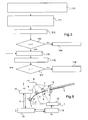
- the device comprises a frame 1 defining a processing path 2 having an inlet 3 and an output sheets.
- a feed tray 5 is mounted on the frame 1 in the vicinity of the inlet 3.
- leaf drive rollers On the frame 1 are conventionally mounted leaf drive rollers in the processing path 2. These include a loader roller 6, a deliasseur roller 7 and several mills 4 which have several rollers on the same axis and two of which are represented here.
- the loader roller 6 is mounted in a manner known per se on a movable support (not visible on the figure 1 ) to project into the tray 5, on the top thereof, and be applied to the top sheet of the sheet package contained in the tray 5.
- the loader roller 6 can be mounted to protrude a bottom of the tray 5 so as to be applied against the bottom sheet of the package.
- the disintegrating roll 7 is mounted projecting in the treatment path 2 in the vicinity of the inlet 3.
- the device comprises a motor 8 to which are connected the loader roller 6, the deliasseur roller 7 and the rolling mills.
- the motor 8 is for example a stepping motor.
- a shredding roll 9 is mounted in the treatment path 2 facing the shredding roll 7.
- a motor 10 is connected to the shredding roll 9 to drive it.
- the motor 10 is a DC motor.
- the deliassing rollers 7 and 9 have a running surface covered with the same material, namely an elastomer, having a high coefficient of friction.
- the motor 8 and the motor 10 are connected to control members 11, 12 respectively which are themselves connected to a control unit 13 comprising for example a microprocessor associated with a memory.
- the control members transmit the power to the motors 8, 10 according to the commands received from the control unit 13.
- the deliassing rollers 7 and 9 can therefore be driven independently of one another.
- the control member 11 is arranged to feed the motor 8 so as to drive the deliasseur roller 7, the loader roller 6 and the rolling mills in a direction S in advance of the sheets from the inlet to the outlet of the treatment path 2
- the deliasseur roller 7 is subjected to a torque C enabling it to exert on each sheet a tangential force T.
- the control member 12 is arranged to feed the motor 10 so as to drive the deliasseur roll 9 in a direction S 'of the sheets back towards the input of the treatment path with a torque C' which is less than the torque C d driving the first deliasseur roller and which allows the deliasseur roller 9 to exert on each sheet a tangential force T 'less than the tangential force T.
- the control member 12 is more specifically designed to supply the motor 10 as a function of a predetermined maximum threshold of the power supply current I.
- the control device 12 comprises, for example, a power supply circuit of the L6219 type.
- the control unit 13 preferably comprises a microprocessor comprising an analog input and an output connected to the control element 12 making it possible to continuously adjust the predetermined maximum threshold I as will be explained hereinafter.
- the deliasseur roller 7 will drive the upper sheet towards the outlet while the deliasseur roller 9 will drive the bottom sheet to the feed tray, the top sheet sliding on the bottom sheet.
- the servocontrol of the motor 10 is therefore performed by the control member 12: it is a hardware control that is reliable and allows low response times compared to a servo-type software.
- control unit 12 When the supply current i of the motor 10 does not reach the predetermined maximum threshold I, the control unit 12 sends a signal to the control unit 13.
- signal is representative of the inequality between the supply current and the predetermined maximum threshold I and normally indicates a power strip (that is to say the simultaneous introduction of several sheets between the separator rollers 7, 9).
- the control unit 13 is programmed to process this signal and stores information in relation to the signal here for the purpose of first performing a diagnosis of the operation of the device (see FIG. figure 2 ).
- the diagnosis assumes that the device is in operation (step 100).
- the control unit 13 performs a sampling at the frequency of calculation of the information representative of the equality of the current i with the threshold I and stores a history of this information on a predetermined number x of memory pages (step 101).
- the control unit 13 checks whether the information reveals that the predetermined maximum threshold I is reached on all x pages (step 102), which would reveal a failure of the motor or the power supply. If the history reveals that the supply current i is always equal to the predetermined maximum threshold I, the control unit 13 is programmed to trigger an alert and a test of the engine 10 (step 103).
- the control unit 13 will further determine the duration d (i ⁇ I) during which the motor is supplied with a current i less than the predetermined maximum threshold I and compare it to a predetermined duration threshold D (step 104).
- the threshold of duration D corresponds to the maximum duration necessary for the return of several sheets snapped by the loader roller 6 together with a sheet intended to be conveyed in the treatment path 2. If the duration d (i ⁇ I) measured is greater than the duration threshold D, the control unit 13 will increment a long power strip meter (step 104). If the number long power strip n (d (i ⁇ I)> D) is greater than an N threshold (comparison made in step 106), the control unit is arranged to trigger an alert and a wear test of separator rollers (step 107).
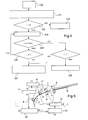
- the control unit checks whether the predetermined maximum threshold I is reached (step 113). If the predetermined maximum threshold I is reached, the control unit 13 issues an alert signaling a fault, for example a message displayed on the screen of the device and requesting the intervention of a technician (step 114).
- control unit 13 When the predetermined maximum threshold I has been set to the minimum value and the current does not reach the predetermined maximum threshold I, the control unit 13 emits an alert signaling a fault, for example a message displayed on the screen of the device and requesting the intervention of a technician (step 128).
- control unit 12 may be forced to control the motor 10 as a function of a maximum value of the predetermined maximum threshold I.
- the control unit 13 may have a dedicated operating mode when the The operator has signaled to him, for example by pressing a preprogrammed key of the device, that the sheets introduced into the feed tray adhere to each other more than normal. In this operating mode, the control unit 13 temporarily forces the control unit 12 to supply the motor with a current i at the maximum value of the predetermined maximum threshold I.
- the device comprises a second loader roller 16 connected to the second motor 10.
- the loader rollers 6, 16 open respectively to the top and bottom of the tray 5 and are disengageably connected to the motor 8 and the motor 10 respectively.
- the rolling mills are connected to the two motors by a walkman system known in itself to be selectively driven in the direction of advance by one or other of the motors 8, 10 rotating in the corresponding direction of advance of said engine .
- the motors 8 and 10 are both DC motors which can be selectively driven either to drive in advance all the rollers loaded with the advancement of the sheets in the processing path 2 or to drive in the direction of delivery the deliasseur roller responsible for pushing the sheets towards the entrance of the treatment path 2.
- the motor control in charge of driving the deliator roller rotating in the discharge direction is identical to that previously described.
- the device comprises a sensor 17 of multi-socket, for example ultrasonic, which makes it possible to determine if several sheets are present simultaneously in the section of the processing path in which it is disposed.
- This detector 17 is connected to the control unit 13.
- the motors 8 and 10 may be DC motors or not.
- the program of the control unit may omit the wear tests of the unwinding roller and / or of the motor failure driving said delaminator roll.
- rollers and rolling mills may be different from those described.
- the invention may have a structure combining the various embodiments and variants.
Landscapes
- Engineering & Computer Science (AREA)
- Mechanical Engineering (AREA)
- Delivering By Means Of Belts And Rollers (AREA)
- Cleaning In Electrography (AREA)
Claims (13)
- Vorrichtung zur Bearbeitung von Blättern, umfassend ein Gehäuse (1), das einen Bearbeitungspfad (2) begrenzt, der einen Einlass (3) und einen Auslass für Blätter hat, ein Zuführfach (5), das an dem Gehäuse nahe dem Einlass (6) gelagert ist, eine in das Fach vorstehende Zuführwalze, eine erste Vereinzelungswalze (7) und eine zweite Vereinzelungswalze (9), die einander gegenüberliegend und nahe dem Einlass in den Bearbeitungspfad vorstehend gelagert sind, einen ersten Motor (8), der mit der ersten Vereinzelungswalze und mit der Zuführwalze verbunden ist, und einen zweiten Motor (10), der mit der zweiten Vereinzelungswalze verbunden ist, dadurch gekennzeichnet, dass ein Steuerelement (12) so ausgebildet ist, dass es den zweiten Motor (10) in Abhängigkeit eines vorgegebenen maximalen Schwellwerts für den Versorgungsstrom versorgt, und dass das Steuerelement mit einer Steuereinheit (13) verbunden ist, die so ausgebildet ist, dass sie ein Signal, das repräsentativ für eine Ungleichheit zwischen dem Versorgungsstrom und dem vorgegebenen maximalen Schwellwert ist, speichert und verarbeitet, derart, dass eine Funktionsdiagnostik der Vorrichtung durchgeführt wird.
- Vorrichtung nach Anspruch 1, wobei das Steuerelement (12) so ausgebildet ist, dass es die zweite Vereinzelungswalze (9) in eine Rückschubrichtung zum Rückschub der Blätter mit einem Drehmoment ansteuert, das kleiner als ein Antriebsdrehmoment der ersten Vereinzelungswalze (7) ist.
- Vorrichtung nach Anspruch 2, wobei der zweite Motor (10) ein Gleichstrommotor ist.
- Vorrichtung nach Anspruch 2, wobei die Steuereinheit (13) so ausgebildet ist, dass sie den vorgegebenen maximalen Schwellwert in Abhängigkeit einer Information bezüglich des Signals modifiziert.
- Vorrichtung nach Anspruch 4, wobei die Steuereinheit (13) so ausgebildet ist, dass sie einen Test des zweiten Motors (10) in Abhängigkeit der Information auslöst.
- Vorrichtung nach Anspruch 5, wobei die Steuereinheit (13) während des Tests des zweiten Motors (10) so ausgebildet ist, dass:- sie die zweite Vereinzelungswalze (9) in eine Vorschubrichtung zum Vorschub der Blätter ansteuert, um gleichzeitig mehrere Blätter zwischen die Vereinzelungswalzen einzuführen,- sie die zweite Vereinzelungswalze in die Rückschubrichtung ansteuert,- und wenn der vorgegebene maximale Schwellwert erreicht ist, sie einen Alarm abgibt, der eine Störung signalisiert.
- Vorrichtung nach Anspruch 5, wobei, wenn der vorgegebene maximale Schwellwert nicht erreicht ist, die Steuereinheit so ausgebildet ist, dass:- sie sukzessive Herabsetzungen des vorgegebenen maximalen Schwellwerts gefolgt von einer Ansteuerung der zweiten Vereinzelungswalze (9) in die Rückschubrichtung durchführt, solange der Versorgungsstrom den vorgegebenen maximalen Schwellwert nicht erreicht,- und wenn der Strom den vorgegebenen Schwellwert erreicht, sie als aktualisierten Wert des vorgegebenen maximalen Schwellwerts den unmittelbar vorausgehenden Wert desselben nimmt.
- Vorrichtung nach Anspruch 2, wobei die Steuereinheit (13) so ausgebildet ist, dass sie einen Verschleißtest der zweiten Vereinzelungswalze (9) in Abhängigkeit einer Information bezüglich des Signals auslöst.
- Vorrichtung nach Anspruch 8, wobei die Steuereinheit (13) während des Verschleißtests so ausgebildet ist, dass:- sie die zweite Vereinzelungswalze (9) bei Nichtvorhandensein von Blättern in die Rückschubrichtung ansteuert,- und wenn der vorgegebene maximale Schwellwert erreicht ist, sie den Test validiert.
- Vorrichtung nach Anspruch 9, wobei, wenn der vorgegebene maximale Schwellwert nicht erreicht ist, die Steuereinheit (13) so ausgebildet ist, dass:- sie sukzessive Herabsetzungen des vorgegebenen maximalen Schwellwerts gefolgt von einer Ansteuerung der zweiten Vereinzelungswalze (9) in die Rückschubrichtung durchführt, solange der Versorgungstrom den vorgegebenen maximalen Schwellwert nicht erreicht und solange ein Minimalwert des vorgegebenen maximalen Schwellwerts nicht erreicht ist,- und wenn der Strom den vorgegebenen Wert erreicht, sie als aktualisierten Wert des vorgegebenen maximalen Schwellwerts den aktuellen Wert desselben nimmt,- wenn der vorgegebene maximale Schwellwert auf den Minimalwert eingestellt wurde und der Strom den vorgegebenen maximalen Schwellwert nicht erreicht, sie einen Alarm abgibt, der eine Störung signalisiert.
- Vorrichtung nach Anspruch 7 oder Anspruch 10, wobei die Steuereinheit (13) dazu gezwungen werden kann, den zweiten Motor (10) in Abhängigkeit eines Maximalwerts des vorgegebenen maximalen Schwellwerts anzutreiben.
- Vorrichtung nach Anspruch 1, wobei ein Detektor zum Erfassen des gleichzeitigen Vorhandenseins mehrerer Blättern in dem Bearbeitungspfad stromabwärts der Vereinzelungswalzen eingebaut ist, wobei der zweite Motor mit einem Steuerelement verbunden ist, dass so ausgebildet ist, dass es den Motor blockiert, wenn ein einziges Blatt erfasst wird, und es die zweite Vereinzelungswalze in eine Rückschubrichtung dreht, wenn mehrere Blätter erfasst werden.
- Vorrichtung nach Anspruch 1, umfassend eine zweite Zuführwalze (16), die mit dem zweiten Motor (10) verbunden ist, wobei die Zuführwalzen über bzw. unter dem Fach (5) münden, wobei die erste Zuführwalze und die zweite Zuführwalze auf lösbare Weise mit dem ersten Motor (8) bzw. dem zweiten Motor (10) verbunden sind.
Applications Claiming Priority (1)
| Application Number | Priority Date | Filing Date | Title |
|---|---|---|---|
| FR0807440A FR2940258B1 (fr) | 2008-12-23 | 2008-12-23 | Dispositif de traitement de feuilles comportant deux rouleaux deliasseurs. |
Publications (3)
| Publication Number | Publication Date |
|---|---|
| EP2202185A2 EP2202185A2 (de) | 2010-06-30 |
| EP2202185A3 EP2202185A3 (de) | 2011-08-31 |
| EP2202185B1 true EP2202185B1 (de) | 2015-11-25 |
Family
ID=40874590
Family Applications (1)
| Application Number | Title | Priority Date | Filing Date |
|---|---|---|---|
| EP09290943.1A Not-in-force EP2202185B1 (de) | 2008-12-23 | 2009-12-15 | Vorrichtung zur Aufbereitung von Blättern einschließlich zwei Rollen zum Formulartrennen |
Country Status (2)
| Country | Link |
|---|---|
| EP (1) | EP2202185B1 (de) |
| FR (1) | FR2940258B1 (de) |
Family Cites Families (6)
| Publication number | Priority date | Publication date | Assignee | Title |
|---|---|---|---|---|
| JPS59149247A (ja) * | 1983-02-16 | 1984-08-27 | Hitachi Ltd | 自動給紙装置 |
| JPH02158533A (ja) * | 1988-12-07 | 1990-06-19 | Fuji Xerox Co Ltd | 画像形成装置のシート送り装置 |
| JP2001213540A (ja) * | 2000-02-03 | 2001-08-07 | Matsushita Electric Ind Co Ltd | 画像処理装置におけるシート材の供給機構 |
| US7334788B2 (en) * | 2003-03-24 | 2008-02-26 | Fuji Xerox Co., Ltd. | Sheet feeder for feeding recording sheets while separating these |
| US7455286B2 (en) * | 2005-06-28 | 2008-11-25 | Hewlett-Packard Development Company, L.P. | Sheet separation using two torque motors |
| JP2007153560A (ja) * | 2005-12-06 | 2007-06-21 | Fuji Xerox Co Ltd | 給紙装置および画像形成装置 |
-
2008
- 2008-12-23 FR FR0807440A patent/FR2940258B1/fr not_active Expired - Fee Related
-
2009
- 2009-12-15 EP EP09290943.1A patent/EP2202185B1/de not_active Not-in-force
Also Published As
| Publication number | Publication date |
|---|---|
| FR2940258B1 (fr) | 2016-07-29 |
| EP2202185A2 (de) | 2010-06-30 |
| FR2940258A1 (fr) | 2010-06-25 |
| EP2202185A3 (de) | 2011-08-31 |
Similar Documents
| Publication | Publication Date | Title |
|---|---|---|
| EP3393229B1 (de) | Elektrischer mäher mit automatischer klingenfreigabe und verfahren zur steuerung des mähers | |
| EP2325120B2 (de) | Vorrichtung zur Auswahl von Postartikeln mit mehreren drehbaren Fingern | |
| US6883408B2 (en) | Method and device for feeding and cutting a rolled transfer paper with improved operability | |
| FR2904244A1 (fr) | Dispositif de broyage pour du materiau plat et procede pour l'exploitation d'un tel dispositif de broyage. | |
| EP1323653B1 (de) | Auswahlvorrichtung für Poststücke | |
| EP2325808B1 (de) | Vorrichtung zur Auswahl von Postartikeln mit perfektionierten Hebeln | |
| EP2202185B1 (de) | Vorrichtung zur Aufbereitung von Blättern einschließlich zwei Rollen zum Formulartrennen | |
| EP0525582B1 (de) | Verfahren zum Vereinzeln von insbesondere offenen Poststücken und Verfahren zum Herstellen von dieser Vorrichtung | |
| EP0856484B1 (de) | Förder-Vorrichtung für Poststücke mit variablen Abmessungen | |
| EP0478430B1 (de) | Friktionstellantrieb | |
| EP1667824B1 (de) | Automatische brotschneidemaschine | |
| EP2292540B1 (de) | Zuführvorrichtung mit verbesserter Umschlagtrennung | |
| JPH11134469A (ja) | 紙葉類計数処理装置 | |
| WO2019026585A1 (ja) | 搬送機構およびこれを備える媒体処理装置、並びに搬送方法 | |
| JP3340326B2 (ja) | 硬貨処理機における硬貨供給装置 | |
| JP3224728B2 (ja) | 硬貨処理機における硬貨供給装置 | |
| EP4153517A1 (de) | Trennvorrichtung zum entfernen eines profils von einer förderfläche und extrusionsmaschine mit einer solchen trennvorrichtung | |
| FR2627763A1 (fr) | Dispositif pour prelever a l'unite des elements en feuille, notamment des documents, a partir d'une pile | |
| FR2874792A1 (fr) | Distributeur de fourrage alimentaire ou de paille et son dispositif de detection automatique de dysfonctionnements | |
| EP1723610A1 (de) | Einrichtung zum abliefern eines tickets für einen thermodruckmechanismus von dergleichen zur ermöglichung der restitution des tickets gegenüber einer umkehr-entnahmesteuerung | |
| EP2305584A1 (de) | Zuführvorrichtung mit kontrollierter Umschlagtrennung | |
| FR2805212A1 (fr) | Machine de traitement de documents tels que du courrier a separateur reglable | |
| KR20010010292A (ko) | 화상형성장치의 걸림 용지 제거 장치 | |
| FR2881375A1 (fr) | Machine a affranchir pour optimiser la qualite d'impression de donnees sensibles sur un article de courrier | |
| FR2712576A1 (fr) | Dépileur de feuilles. |
Legal Events
| Date | Code | Title | Description |
|---|---|---|---|
| PUAI | Public reference made under article 153(3) epc to a published international application that has entered the european phase |
Free format text: ORIGINAL CODE: 0009012 |
|
| AK | Designated contracting states |
Kind code of ref document: A2 Designated state(s): AT BE BG CH CY CZ DE DK EE ES FI FR GB GR HR HU IE IS IT LI LT LU LV MC MK MT NL NO PL PT RO SE SI SK SM TR |
|
| AX | Request for extension of the european patent |
Extension state: AL BA RS |
|
| RAP1 | Party data changed (applicant data changed or rights of an application transferred) |
Owner name: SAGECOM DOCUMENTS SAS |
|
| RAP1 | Party data changed (applicant data changed or rights of an application transferred) |
Owner name: SAGEMCOM DOCUMENTS SAS |
|
| PUAL | Search report despatched |
Free format text: ORIGINAL CODE: 0009013 |
|
| AK | Designated contracting states |
Kind code of ref document: A3 Designated state(s): AT BE BG CH CY CZ DE DK EE ES FI FR GB GR HR HU IE IS IT LI LT LU LV MC MK MT NL NO PL PT RO SE SI SK SM TR |
|
| AX | Request for extension of the european patent |
Extension state: AL BA RS |
|
| RIC1 | Information provided on ipc code assigned before grant |
Ipc: B65H 3/06 20060101ALI20110728BHEP Ipc: B65H 3/52 20060101AFI20110728BHEP |
|
| 17P | Request for examination filed |
Effective date: 20120228 |
|
| 17Q | First examination report despatched |
Effective date: 20130612 |
|
| GRAP | Despatch of communication of intention to grant a patent |
Free format text: ORIGINAL CODE: EPIDOSNIGR1 |
|
| INTG | Intention to grant announced |
Effective date: 20150611 |
|
| GRAS | Grant fee paid |
Free format text: ORIGINAL CODE: EPIDOSNIGR3 |
|
| GRAA | (expected) grant |
Free format text: ORIGINAL CODE: 0009210 |
|
| RIN1 | Information on inventor provided before grant (corrected) |
Inventor name: MARCQ, FREDERIC Inventor name: IMBERT, NICOLAS |
|
| AK | Designated contracting states |
Kind code of ref document: B1 Designated state(s): AT BE BG CH CY CZ DE DK EE ES FI FR GB GR HR HU IE IS IT LI LT LU LV MC MK MT NL NO PL PT RO SE SI SK SM TR |
|
| REG | Reference to a national code |
Ref country code: GB Ref legal event code: FG4D Free format text: NOT ENGLISH |
|
| REG | Reference to a national code |
Ref country code: CH Ref legal event code: EP |
|
| REG | Reference to a national code |
Ref country code: AT Ref legal event code: REF Ref document number: 762474 Country of ref document: AT Kind code of ref document: T Effective date: 20151215 |
|
| REG | Reference to a national code |
Ref country code: IE Ref legal event code: FG4D Free format text: LANGUAGE OF EP DOCUMENT: FRENCH |
|
| REG | Reference to a national code |
Ref country code: FR Ref legal event code: PLFP Year of fee payment: 7 |
|
| REG | Reference to a national code |
Ref country code: DE Ref legal event code: R096 Ref document number: 602009034944 Country of ref document: DE |
|
| REG | Reference to a national code |
Ref country code: LT Ref legal event code: MG4D |
|
| REG | Reference to a national code |
Ref country code: NL Ref legal event code: MP Effective date: 20160225 |
|
| REG | Reference to a national code |
Ref country code: AT Ref legal event code: MK05 Ref document number: 762474 Country of ref document: AT Kind code of ref document: T Effective date: 20151125 |
|
| PG25 | Lapsed in a contracting state [announced via postgrant information from national office to epo] |
Ref country code: NO Free format text: LAPSE BECAUSE OF FAILURE TO SUBMIT A TRANSLATION OF THE DESCRIPTION OR TO PAY THE FEE WITHIN THE PRESCRIBED TIME-LIMIT Effective date: 20160225 Ref country code: HR Free format text: LAPSE BECAUSE OF FAILURE TO SUBMIT A TRANSLATION OF THE DESCRIPTION OR TO PAY THE FEE WITHIN THE PRESCRIBED TIME-LIMIT Effective date: 20151125 Ref country code: NL Free format text: LAPSE BECAUSE OF FAILURE TO SUBMIT A TRANSLATION OF THE DESCRIPTION OR TO PAY THE FEE WITHIN THE PRESCRIBED TIME-LIMIT Effective date: 20151125 Ref country code: IS Free format text: LAPSE BECAUSE OF FAILURE TO SUBMIT A TRANSLATION OF THE DESCRIPTION OR TO PAY THE FEE WITHIN THE PRESCRIBED TIME-LIMIT Effective date: 20160325 Ref country code: LT Free format text: LAPSE BECAUSE OF FAILURE TO SUBMIT A TRANSLATION OF THE DESCRIPTION OR TO PAY THE FEE WITHIN THE PRESCRIBED TIME-LIMIT Effective date: 20151125 Ref country code: ES Free format text: LAPSE BECAUSE OF FAILURE TO SUBMIT A TRANSLATION OF THE DESCRIPTION OR TO PAY THE FEE WITHIN THE PRESCRIBED TIME-LIMIT Effective date: 20151125 |
|
| PG25 | Lapsed in a contracting state [announced via postgrant information from national office to epo] |
Ref country code: PL Free format text: LAPSE BECAUSE OF FAILURE TO SUBMIT A TRANSLATION OF THE DESCRIPTION OR TO PAY THE FEE WITHIN THE PRESCRIBED TIME-LIMIT Effective date: 20151125 Ref country code: LV Free format text: LAPSE BECAUSE OF FAILURE TO SUBMIT A TRANSLATION OF THE DESCRIPTION OR TO PAY THE FEE WITHIN THE PRESCRIBED TIME-LIMIT Effective date: 20151125 Ref country code: AT Free format text: LAPSE BECAUSE OF FAILURE TO SUBMIT A TRANSLATION OF THE DESCRIPTION OR TO PAY THE FEE WITHIN THE PRESCRIBED TIME-LIMIT Effective date: 20151125 Ref country code: PT Free format text: LAPSE BECAUSE OF FAILURE TO SUBMIT A TRANSLATION OF THE DESCRIPTION OR TO PAY THE FEE WITHIN THE PRESCRIBED TIME-LIMIT Effective date: 20160325 Ref country code: SE Free format text: LAPSE BECAUSE OF FAILURE TO SUBMIT A TRANSLATION OF THE DESCRIPTION OR TO PAY THE FEE WITHIN THE PRESCRIBED TIME-LIMIT Effective date: 20151125 Ref country code: BE Free format text: LAPSE BECAUSE OF NON-PAYMENT OF DUE FEES Effective date: 20151231 Ref country code: FI Free format text: LAPSE BECAUSE OF FAILURE TO SUBMIT A TRANSLATION OF THE DESCRIPTION OR TO PAY THE FEE WITHIN THE PRESCRIBED TIME-LIMIT Effective date: 20151125 Ref country code: GR Free format text: LAPSE BECAUSE OF FAILURE TO SUBMIT A TRANSLATION OF THE DESCRIPTION OR TO PAY THE FEE WITHIN THE PRESCRIBED TIME-LIMIT Effective date: 20160226 |
|
| PG25 | Lapsed in a contracting state [announced via postgrant information from national office to epo] |
Ref country code: IT Free format text: LAPSE BECAUSE OF FAILURE TO SUBMIT A TRANSLATION OF THE DESCRIPTION OR TO PAY THE FEE WITHIN THE PRESCRIBED TIME-LIMIT Effective date: 20151125 Ref country code: CZ Free format text: LAPSE BECAUSE OF FAILURE TO SUBMIT A TRANSLATION OF THE DESCRIPTION OR TO PAY THE FEE WITHIN THE PRESCRIBED TIME-LIMIT Effective date: 20151125 |
|
| REG | Reference to a national code |
Ref country code: CH Ref legal event code: PL |
|
| REG | Reference to a national code |
Ref country code: DE Ref legal event code: R097 Ref document number: 602009034944 Country of ref document: DE |
|
| PG25 | Lapsed in a contracting state [announced via postgrant information from national office to epo] |
Ref country code: SM Free format text: LAPSE BECAUSE OF FAILURE TO SUBMIT A TRANSLATION OF THE DESCRIPTION OR TO PAY THE FEE WITHIN THE PRESCRIBED TIME-LIMIT Effective date: 20151125 Ref country code: SK Free format text: LAPSE BECAUSE OF FAILURE TO SUBMIT A TRANSLATION OF THE DESCRIPTION OR TO PAY THE FEE WITHIN THE PRESCRIBED TIME-LIMIT Effective date: 20151125 Ref country code: EE Free format text: LAPSE BECAUSE OF FAILURE TO SUBMIT A TRANSLATION OF THE DESCRIPTION OR TO PAY THE FEE WITHIN THE PRESCRIBED TIME-LIMIT Effective date: 20151125 Ref country code: DK Free format text: LAPSE BECAUSE OF FAILURE TO SUBMIT A TRANSLATION OF THE DESCRIPTION OR TO PAY THE FEE WITHIN THE PRESCRIBED TIME-LIMIT Effective date: 20151125 Ref country code: RO Free format text: LAPSE BECAUSE OF FAILURE TO SUBMIT A TRANSLATION OF THE DESCRIPTION OR TO PAY THE FEE WITHIN THE PRESCRIBED TIME-LIMIT Effective date: 20151125 |
|
| REG | Reference to a national code |
Ref country code: IE Ref legal event code: MM4A |
|
| PG25 | Lapsed in a contracting state [announced via postgrant information from national office to epo] |
Ref country code: MC Free format text: LAPSE BECAUSE OF FAILURE TO SUBMIT A TRANSLATION OF THE DESCRIPTION OR TO PAY THE FEE WITHIN THE PRESCRIBED TIME-LIMIT Effective date: 20151125 |
|
| PLBE | No opposition filed within time limit |
Free format text: ORIGINAL CODE: 0009261 |
|
| STAA | Information on the status of an ep patent application or granted ep patent |
Free format text: STATUS: NO OPPOSITION FILED WITHIN TIME LIMIT |
|
| PG25 | Lapsed in a contracting state [announced via postgrant information from national office to epo] |
Ref country code: IE Free format text: LAPSE BECAUSE OF NON-PAYMENT OF DUE FEES Effective date: 20151215 Ref country code: LI Free format text: LAPSE BECAUSE OF NON-PAYMENT OF DUE FEES Effective date: 20151231 Ref country code: CH Free format text: LAPSE BECAUSE OF NON-PAYMENT OF DUE FEES Effective date: 20151231 |
|
| 26N | No opposition filed |
Effective date: 20160826 |
|
| REG | Reference to a national code |
Ref country code: FR Ref legal event code: PLFP Year of fee payment: 8 |
|
| PG25 | Lapsed in a contracting state [announced via postgrant information from national office to epo] |
Ref country code: SI Free format text: LAPSE BECAUSE OF FAILURE TO SUBMIT A TRANSLATION OF THE DESCRIPTION OR TO PAY THE FEE WITHIN THE PRESCRIBED TIME-LIMIT Effective date: 20151125 |
|
| PGFP | Annual fee paid to national office [announced via postgrant information from national office to epo] |
Ref country code: DE Payment date: 20161121 Year of fee payment: 8 Ref country code: GB Payment date: 20161128 Year of fee payment: 8 Ref country code: FR Payment date: 20161121 Year of fee payment: 8 |
|
| PG25 | Lapsed in a contracting state [announced via postgrant information from national office to epo] |
Ref country code: HU Free format text: LAPSE BECAUSE OF FAILURE TO SUBMIT A TRANSLATION OF THE DESCRIPTION OR TO PAY THE FEE WITHIN THE PRESCRIBED TIME-LIMIT; INVALID AB INITIO Effective date: 20091215 Ref country code: BG Free format text: LAPSE BECAUSE OF FAILURE TO SUBMIT A TRANSLATION OF THE DESCRIPTION OR TO PAY THE FEE WITHIN THE PRESCRIBED TIME-LIMIT Effective date: 20151125 |
|
| PG25 | Lapsed in a contracting state [announced via postgrant information from national office to epo] |
Ref country code: CY Free format text: LAPSE BECAUSE OF FAILURE TO SUBMIT A TRANSLATION OF THE DESCRIPTION OR TO PAY THE FEE WITHIN THE PRESCRIBED TIME-LIMIT Effective date: 20151125 |
|
| PG25 | Lapsed in a contracting state [announced via postgrant information from national office to epo] |
Ref country code: TR Free format text: LAPSE BECAUSE OF FAILURE TO SUBMIT A TRANSLATION OF THE DESCRIPTION OR TO PAY THE FEE WITHIN THE PRESCRIBED TIME-LIMIT Effective date: 20151125 Ref country code: MT Free format text: LAPSE BECAUSE OF FAILURE TO SUBMIT A TRANSLATION OF THE DESCRIPTION OR TO PAY THE FEE WITHIN THE PRESCRIBED TIME-LIMIT Effective date: 20151125 |
|
| PG25 | Lapsed in a contracting state [announced via postgrant information from national office to epo] |
Ref country code: LU Free format text: LAPSE BECAUSE OF NON-PAYMENT OF DUE FEES Effective date: 20151215 |
|
| PG25 | Lapsed in a contracting state [announced via postgrant information from national office to epo] |
Ref country code: MK Free format text: LAPSE BECAUSE OF FAILURE TO SUBMIT A TRANSLATION OF THE DESCRIPTION OR TO PAY THE FEE WITHIN THE PRESCRIBED TIME-LIMIT Effective date: 20151125 |
|
| REG | Reference to a national code |
Ref country code: DE Ref legal event code: R119 Ref document number: 602009034944 Country of ref document: DE |
|
| GBPC | Gb: european patent ceased through non-payment of renewal fee |
Effective date: 20171215 |
|
| REG | Reference to a national code |
Ref country code: FR Ref legal event code: ST Effective date: 20180831 |
|
| PG25 | Lapsed in a contracting state [announced via postgrant information from national office to epo] |
Ref country code: FR Free format text: LAPSE BECAUSE OF NON-PAYMENT OF DUE FEES Effective date: 20180102 Ref country code: DE Free format text: LAPSE BECAUSE OF NON-PAYMENT OF DUE FEES Effective date: 20180703 |
|
| PG25 | Lapsed in a contracting state [announced via postgrant information from national office to epo] |
Ref country code: GB Free format text: LAPSE BECAUSE OF NON-PAYMENT OF DUE FEES Effective date: 20171215 |