EP2305584A1 - Zuführvorrichtung mit kontrollierter Umschlagtrennung - Google Patents
Zuführvorrichtung mit kontrollierter Umschlagtrennung Download PDFInfo
- Publication number
- EP2305584A1 EP2305584A1 EP10178398A EP10178398A EP2305584A1 EP 2305584 A1 EP2305584 A1 EP 2305584A1 EP 10178398 A EP10178398 A EP 10178398A EP 10178398 A EP10178398 A EP 10178398A EP 2305584 A1 EP2305584 A1 EP 2305584A1
- Authority
- EP
- European Patent Office
- Prior art keywords
- mail items
- measurement
- zone
- rollers
- successive
- Prior art date
- Legal status (The legal status is an assumption and is not a legal conclusion. Google has not performed a legal analysis and makes no representation as to the accuracy of the status listed.)
- Withdrawn
Links
- 238000000926 separation method Methods 0.000 title claims abstract description 38
- 238000005259 measurement Methods 0.000 claims abstract description 14
- 238000012937 correction Methods 0.000 claims abstract description 11
- 238000011144 upstream manufacturing Methods 0.000 claims abstract description 5
- 238000001514 detection method Methods 0.000 claims description 10
- 238000000034 method Methods 0.000 claims description 10
- 230000005540 biological transmission Effects 0.000 description 5
- 238000012360 testing method Methods 0.000 description 4
- 230000004044 response Effects 0.000 description 3
- 238000012549 training Methods 0.000 description 3
- 238000000605 extraction Methods 0.000 description 2
- 230000008569 process Effects 0.000 description 2
- 238000012545 processing Methods 0.000 description 2
- 230000008859 change Effects 0.000 description 1
- 238000010586 diagram Methods 0.000 description 1
- 238000012986 modification Methods 0.000 description 1
- 230000004048 modification Effects 0.000 description 1
- 230000003287 optical effect Effects 0.000 description 1
- 230000009467 reduction Effects 0.000 description 1
- 238000012163 sequencing technique Methods 0.000 description 1
- 239000007858 starting material Substances 0.000 description 1
- 230000002123 temporal effect Effects 0.000 description 1
- 238000012546 transfer Methods 0.000 description 1
Images
Classifications
-
- B—PERFORMING OPERATIONS; TRANSPORTING
- B65—CONVEYING; PACKING; STORING; HANDLING THIN OR FILAMENTARY MATERIAL
- B65H—HANDLING THIN OR FILAMENTARY MATERIAL, e.g. SHEETS, WEBS, CABLES
- B65H7/00—Controlling article feeding, separating, pile-advancing, or associated apparatus, to take account of incorrect feeding, absence of articles, or presence of faulty articles
- B65H7/02—Controlling article feeding, separating, pile-advancing, or associated apparatus, to take account of incorrect feeding, absence of articles, or presence of faulty articles by feelers or detectors
- B65H7/06—Controlling article feeding, separating, pile-advancing, or associated apparatus, to take account of incorrect feeding, absence of articles, or presence of faulty articles by feelers or detectors responsive to presence of faulty articles or incorrect separation or feed
-
- B—PERFORMING OPERATIONS; TRANSPORTING
- B65—CONVEYING; PACKING; STORING; HANDLING THIN OR FILAMENTARY MATERIAL
- B65H—HANDLING THIN OR FILAMENTARY MATERIAL, e.g. SHEETS, WEBS, CABLES
- B65H2220/00—Function indicators
- B65H2220/01—Function indicators indicating an entity as a function of which control, adjustment or change is performed, i.e. input
-
- B—PERFORMING OPERATIONS; TRANSPORTING
- B65—CONVEYING; PACKING; STORING; HANDLING THIN OR FILAMENTARY MATERIAL
- B65H—HANDLING THIN OR FILAMENTARY MATERIAL, e.g. SHEETS, WEBS, CABLES
- B65H2301/00—Handling processes for sheets or webs
- B65H2301/40—Type of handling process
- B65H2301/44—Moving, forwarding, guiding material
- B65H2301/445—Moving, forwarding, guiding material stream of articles separated from each other
- B65H2301/4452—Regulating space between separated articles
- B65H2301/44522—Varying space between separated articles
-
- B—PERFORMING OPERATIONS; TRANSPORTING
- B65—CONVEYING; PACKING; STORING; HANDLING THIN OR FILAMENTARY MATERIAL
- B65H—HANDLING THIN OR FILAMENTARY MATERIAL, e.g. SHEETS, WEBS, CABLES
- B65H2511/00—Dimensions; Position; Numbers; Identification; Occurrences
- B65H2511/20—Location in space
- B65H2511/22—Distance
-
- B—PERFORMING OPERATIONS; TRANSPORTING
- B65—CONVEYING; PACKING; STORING; HANDLING THIN OR FILAMENTARY MATERIAL
- B65H—HANDLING THIN OR FILAMENTARY MATERIAL, e.g. SHEETS, WEBS, CABLES
- B65H2513/00—Dynamic entities; Timing aspects
- B65H2513/10—Speed
-
- B—PERFORMING OPERATIONS; TRANSPORTING
- B65—CONVEYING; PACKING; STORING; HANDLING THIN OR FILAMENTARY MATERIAL
- B65H—HANDLING THIN OR FILAMENTARY MATERIAL, e.g. SHEETS, WEBS, CABLES
- B65H2513/00—Dynamic entities; Timing aspects
- B65H2513/10—Speed
- B65H2513/11—Speed angular
-
- B—PERFORMING OPERATIONS; TRANSPORTING
- B65—CONVEYING; PACKING; STORING; HANDLING THIN OR FILAMENTARY MATERIAL
- B65H—HANDLING THIN OR FILAMENTARY MATERIAL, e.g. SHEETS, WEBS, CABLES
- B65H2557/00—Means for control not provided for in groups B65H2551/00 - B65H2555/00
- B65H2557/20—Calculating means; Controlling methods
- B65H2557/24—Calculating methods; Mathematic models
- B65H2557/242—Calculating methods; Mathematic models involving a particular data profile or curve
-
- B—PERFORMING OPERATIONS; TRANSPORTING
- B65—CONVEYING; PACKING; STORING; HANDLING THIN OR FILAMENTARY MATERIAL
- B65H—HANDLING THIN OR FILAMENTARY MATERIAL, e.g. SHEETS, WEBS, CABLES
- B65H2701/00—Handled material; Storage means
- B65H2701/10—Handled articles or webs
- B65H2701/19—Specific article or web
- B65H2701/1916—Envelopes and articles of mail
Definitions
- the present invention relates exclusively to the field of mail processing and more particularly relates to a device for supplying mail items for a franking machine ensuring improved separation of mail items.
- a franking machine must be adapted to receive different types of mail items such as documents, folds or envelopes with varying dimensions.
- it often includes upstream automatic feeding device for particular the conveying of these mail items at rates adapted to their processing by the franking machine.
- This automatic feeding device, or feeder, on the receiving tray of which is arranged a stack of mail items often of variable size usually comprises means for unstacking, separating, transporting and possibly closing the mail items which must then be processed by the franking machine.
- the role of the stripping means consisting of motorized drive rollers is to deliver to the selection means a small packet of mail items extracted from the pile of mail items present on the receiving tray of the feeder so that those they separate them one by one while ensuring a predetermined interval between two successive mail items.
- This separation interval is particularly important because, if it is too small, the franking machine will not have time to proceed with the calculation of the postage stamp and it will then have to stop and, if it is too big, the rate of postage of mail items will be significantly reduced.
- the quality of the selection depends greatly on the quality of the presentation of the mail items to the selection means.
- the mail items are conveyed from the store to the separation zone at constant speed, and the management of the separation interval is performed at the output of the selection means by delivering the mail items with a determined separation interval and this regardless of the interval existing at the input of these selection means.
- this type of management is not satisfactory because, depending on the texture and weight of the mail items or the wear of the training rollers, the mail items extracted from the store will be pushed more or less far in the separation zone.
- the separation interval between two mail items will be more (if the article is too advanced) or less (if not sufficiently advanced) important than the one actually desired.
- said predetermined correction threshold is between plus or minus 8 to 12% of said predefined interval value.
- said measurement is an instantaneous value obtained during the detection of the passage of two successive mail articles or an average value obtained during the detection of the passage of several successive mailpieces.
- the invention also relates to the associated method of controlling the drive rollers.
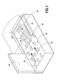
- Automatic feeding device for mail items as illustrated in FIG. figure 1 , comprises a feed zone 10 formed essentially of a receiving plate 12 and a longitudinal reference wall 14 and intended to receive a stack of mail items arranged in particular in bulk (so-called mixed mail) and therefore able to have variable dimensions and weights.
- This zone comprises means of transport comprising a first plurality of drive rollers 16 for moving mailpieces downstream at a separation zone 18 comprising selection means comprising a presser and a die (no shown) cooperating with a second plurality of drive rollers 20 and from which these items are individually extracted from the stack.
- superimposed conveying means comprising a third plurality of drive rollers 22 (the associated upper free rollers are not shown) are provided in a conveying zone 24 at the exit of this separation zone to transfer to the franking machine. arranged downstream the mail items thus extracted one by one.
- the supply device further comprises various known control and control means (not shown with the exception of a main drive motor 28 and a microprocessor control box 30) necessary for its operation, in particular for the actuation of the different drive rollers 16, 20, 22 during the movement of the mail items along a transport path 32, and it is therefore unnecessary to describe here in more detail.
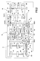
- the figure 2 shows more precisely the different drive rollers of such an automatic feeding device.
- This comprises successively, in the direction of advance of a mail piece along the transport path 32, three sets 100, 102, 104 of three drive rollers 16 mounted in parallel on three axes of rotation 106, 108, 110 arranged perpendicularly to the transport path 32 at the feed zone 10, two sets 180, 182 of three drive rollers 20 also mounted parallel on two axes of rotation 184, 186 arranged perpendicularly to the transport path 32 at the selection zone 18, and two sets 240, 242 of three rear drive rollers 22 and front mounted on two parallel shafts 244, 246 at the conveying zone 24.
- the gear 52 mounted on the axis of rotation 184 closest to the feed zone 10 meshes with a first intermediate gear 56 which in turn meshes with a pinion 58 mounted on a fifth transmission shaft 60 which also carries a second gear. clutch 62 (also referenced E2).
- Another gear 64 also mounted on this fifth shaft 60 meshes through a second intermediate gear 66 on a pinion 68 integral with the axis 110 for holding the feed rollers 16; 104 located closest to the separation zone 18.
- This axis comprises another pinion 70 which in turn drives, via a third intermediate gear 72, a pinion 74 mounted on a sixth transmission shaft 76 which also carries a third clutch 78 (referenced also E3).
- the second clutch E2 when activated, drives the rollers of the last set 104 (those arranged at the outlet of the feed zone) simultaneously with those of the separation and conveying zones and that the third clutch E3 drives all the rollers of the feed zone together with those of the two other zones of the device, when it is in turn activated.
- the assembly 240 of drive rollers 22 of the conveying zone located closest to the selection zone 18 comprises a first sensor 120 (C1) for detecting the presence of a mailpiece at the entrance to this conveying zone. 24.
- the set 186 of drive rollers 20 of the selection zone 18 located closer to the exit of the conveying zone comprises a second sensor 122 (C2) for detecting the presence of an article. mail in the separation zone, preferably at the exit of this zone.
- These two sensors which are advantageously of the optical type, may in the opto-mechanical variant illustrated each comprise, for example, a flag or flap 120A, 122A which is actuated at the passage of a front of the article of mail and whose rotation interrupts the light path of a diode (or between two diodes) electroluminescent contained in a housing 120B, 122B secured to the body of the supply device.
- three other sensors may be arranged. detect the format of mail items.
- a third sensor 124 (C3) for the detection of small mail items (i.e. up to about 160 mm) is placed closer to this wall and a fourth sensor 126 (C4) is placed substantially towards the middle part of this area for the detection of medium format mailpieces (ie understood between about 160 mm and about 240 mm) and finally a fifth sensor 128 (C5), even further from the wall 14, for the detection of large format articles (ie beyond about 240 mm).
- the number and location of these sensors is in no way limiting. Indeed, it is quite possible to have a number of sensors more or less important and in particular to have as many sensors that it is desired to detect formats of mail items.
- the separation interval is used not only to control the clutch of the extraction rollers but also and especially the speed of the drive rollers of the receiving tray.
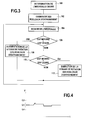
- the interval separating two items of mail preferably measured using the C1 sensor and compared with a desired interval depending on the desired rate of transport according to the process now described with respect to the figure 3 .
- the desired transport rate for conveying mail items to the downstream franking machine sets the desired separation interval between two successive mail items. Its automatic determination by the control and control means of the supply device from a predefined transport rate for example at the keyboard of this device is performed in a first initialization step 100 of the method of the invention.
- a next step 102 the mail items having been loaded on the receiving tray, the device is started ordering the different drive rolls and thus the process of selecting the mail items one by one.
- a measurement is then made of the interval separating two mail items leaving the selection means, this measurement being preferably an average measurement made for example on ten successive mailpieces and then, this measurement of the separation interval is compared with the desired predetermined separation interval (tests of steps 106 and 110).
- step 108 is used to increase the rotation speed of the drive rolls of the receiving tray to force the arrival to the means for selecting the mail items. If, on the contrary, it appears that the measured value is less than that desired at the predefined correction threshold (response yes to the test of step 110), then a reduction in the speed of rotation of the training rolls of the receiving tray to slow down the arrival at the means of selection of mail items.
- This correction threshold may be evaluated at about 10% of the desired range, preferably between 8 and 12%.
- this speed is constant and determined by the desired transport speed
- it varies according to the separation interval measured. This variation is carried out discontinuously, in steps of 0.02 m / s for a transport speed of 0.5 m / s, for example.
- the threshold of variation of the transport speed can be doubled, or in the above example, brought to 0, 04m / s instead of 0.02m / s. In general, this threshold may be between 4 and 10% of the transport speed.
- the structure of a conventional feeder is in no way modified at the hardware level and, at the software level, it is simply defined a different sequencing for the control of training rollers of the receiving tray.
- the reliability of the feed device according to the invention is not changed and the separation of mail items is significantly improved.
Landscapes
- Sheets, Magazines, And Separation Thereof (AREA)
- Sorting Of Articles (AREA)
- Delivering By Means Of Belts And Rollers (AREA)
Applications Claiming Priority (1)
| Application Number | Priority Date | Filing Date | Title |
|---|---|---|---|
| FR0956902A FR2950873B1 (fr) | 2009-10-02 | 2009-10-02 | Dispositif d'alimentation a separation d'enveloppes controlee |
Publications (1)
| Publication Number | Publication Date |
|---|---|
| EP2305584A1 true EP2305584A1 (de) | 2011-04-06 |
Family
ID=42126031
Family Applications (1)
| Application Number | Title | Priority Date | Filing Date |
|---|---|---|---|
| EP10178398A Withdrawn EP2305584A1 (de) | 2009-10-02 | 2010-09-22 | Zuführvorrichtung mit kontrollierter Umschlagtrennung |
Country Status (3)
| Country | Link |
|---|---|
| US (1) | US20110079951A1 (de) |
| EP (1) | EP2305584A1 (de) |
| FR (1) | FR2950873B1 (de) |
Citations (6)
| Publication number | Priority date | Publication date | Assignee | Title |
|---|---|---|---|---|
| US4077620A (en) * | 1976-03-27 | 1978-03-07 | Licentia Patent-Verwaltungs-Gmbh | Apparatus for the successive release of items of mail from a stack |
| EP0856484A1 (de) * | 1997-01-31 | 1998-08-05 | Neopost Industrie | Förder-Vorrichtung für Poststücke mit variablen Abmessungen |
| US6378859B1 (en) * | 1998-01-15 | 2002-04-30 | Siemens Aktiengesellschaft | Method for controlling a device used to remove packages from a pile |
| US6554275B1 (en) * | 2001-12-04 | 2003-04-29 | Unisys Corporation | Method and system for document overlap/gap error detection and correction |
| EP1306336A2 (de) * | 2001-10-26 | 2003-05-02 | Pitney Bowes Inc. | Dynamische Abstandskorrektur für eine Kuvertierssubsystem |
| US20030168798A1 (en) * | 2002-03-11 | 2003-09-11 | Pitney Bowes Incorporated | Transport method and system for controlling timing of mail pieces being processed by a mailing system |
Family Cites Families (1)
| Publication number | Priority date | Publication date | Assignee | Title |
|---|---|---|---|---|
| JP2005330065A (ja) * | 2004-05-20 | 2005-12-02 | Toshiba Corp | 紙葉類取出装置 |
-
2009
- 2009-10-02 FR FR0956902A patent/FR2950873B1/fr not_active Expired - Fee Related
-
2010
- 2010-09-22 EP EP10178398A patent/EP2305584A1/de not_active Withdrawn
- 2010-10-01 US US12/896,121 patent/US20110079951A1/en not_active Abandoned
Patent Citations (6)
| Publication number | Priority date | Publication date | Assignee | Title |
|---|---|---|---|---|
| US4077620A (en) * | 1976-03-27 | 1978-03-07 | Licentia Patent-Verwaltungs-Gmbh | Apparatus for the successive release of items of mail from a stack |
| EP0856484A1 (de) * | 1997-01-31 | 1998-08-05 | Neopost Industrie | Förder-Vorrichtung für Poststücke mit variablen Abmessungen |
| US6378859B1 (en) * | 1998-01-15 | 2002-04-30 | Siemens Aktiengesellschaft | Method for controlling a device used to remove packages from a pile |
| EP1306336A2 (de) * | 2001-10-26 | 2003-05-02 | Pitney Bowes Inc. | Dynamische Abstandskorrektur für eine Kuvertierssubsystem |
| US6554275B1 (en) * | 2001-12-04 | 2003-04-29 | Unisys Corporation | Method and system for document overlap/gap error detection and correction |
| US20030168798A1 (en) * | 2002-03-11 | 2003-09-11 | Pitney Bowes Incorporated | Transport method and system for controlling timing of mail pieces being processed by a mailing system |
Also Published As
| Publication number | Publication date |
|---|---|
| FR2950873A1 (fr) | 2011-04-08 |
| US20110079951A1 (en) | 2011-04-07 |
| FR2950873B1 (fr) | 2011-12-16 |
Similar Documents
| Publication | Publication Date | Title |
|---|---|---|
| EP2222586B1 (de) | Vorrichtung zur entstapelung multimodaler postsendungen | |
| FR2604106A1 (fr) | Systeme d'expedition postale pour des lettres possedant des poids differents | |
| FR2604254A1 (fr) | Module de pesee, notamment pour machines d'expedition postales | |
| JP3923085B2 (ja) | スタックから扁平な郵送物を取り出すための装置を制御する方法 | |
| EP0906880A1 (de) | Fördervorrichtung für ein Posthandhabungssystem | |
| EP3528968B1 (de) | Obstsortiertisch mit adaptivem sieb | |
| EP1902989B1 (de) | Vorrichtung zum Entstapeln von Postsendungen mit optimierter Verwaltung der Entstapelbedingungen | |
| EP2605867B1 (de) | Postsortiermaschine mit klemmförderung und verfahren zum betrieb derselbigen | |
| FR2604105A1 (fr) | Module d'alimentation, notamment pour une machine d'expedition postale | |
| EP0856484B1 (de) | Förder-Vorrichtung für Poststücke mit variablen Abmessungen | |
| EP2277810B1 (de) | Versorgungsvorrichtung mit verbesserter Adhärenz | |
| FR2797437A1 (fr) | Dispositif de convoyage d'objets plats avec un systeme de synchronisation | |
| EP2292540B1 (de) | Zuführvorrichtung mit verbesserter Umschlagtrennung | |
| EP1923340B1 (de) | Vorrichtung zum automatischen Laden von Umschlägen | |
| EP2413291B1 (de) | Vorrichtung zur Auswahl von losen Postartikeln | |
| EP2305584A1 (de) | Zuführvorrichtung mit kontrollierter Umschlagtrennung | |
| FR2697516A1 (fr) | Dispositif de distribution unitaire d'objets minces empilés. | |
| EP0653729A1 (de) | Zuführeinrichtung für Briefumschläge mit einer Waage | |
| FR2544668A1 (fr) | Machine a plier et a inserer des lettres dans des enveloppes | |
| EP2199237B1 (de) | Perfektionierte Einspeisevorrichtung für Postartikel | |
| FR2521962A1 (fr) | Depileur d'objets plats tels que les plis postaux | |
| CA2484589A1 (fr) | Procede d'impression pour machine compacte et machine associee | |
| WO2003035527A1 (fr) | Dispositif pour la mise en pile d'objets plats tels que plis postaux | |
| EP2364786B1 (de) | Postsortiervorrichtung und -verfahren mit selektiver Wägung | |
| EP0550746A1 (de) | Maschine zum behandeln flacher gegenstände |
Legal Events
| Date | Code | Title | Description |
|---|---|---|---|
| PUAI | Public reference made under article 153(3) epc to a published international application that has entered the european phase |
Free format text: ORIGINAL CODE: 0009012 |
|
| AK | Designated contracting states |
Kind code of ref document: A1 Designated state(s): AL AT BE BG CH CY CZ DE DK EE ES FI FR GB GR HR HU IE IS IT LI LT LU LV MC MK MT NL NO PL PT RO SE SI SK SM TR |
|
| AX | Request for extension of the european patent |
Extension state: BA ME RS |
|
| 17P | Request for examination filed |
Effective date: 20110914 |
|
| 17Q | First examination report despatched |
Effective date: 20141015 |
|
| STAA | Information on the status of an ep patent application or granted ep patent |
Free format text: STATUS: THE APPLICATION IS DEEMED TO BE WITHDRAWN |
|
| 18D | Application deemed to be withdrawn |
Effective date: 20150226 |