EP2201886A1 - Spülgutträger mit einem Anschlussstück für schlauchförmiges Reinigungsgut - Google Patents
Spülgutträger mit einem Anschlussstück für schlauchförmiges Reinigungsgut Download PDFInfo
- Publication number
- EP2201886A1 EP2201886A1 EP09401039A EP09401039A EP2201886A1 EP 2201886 A1 EP2201886 A1 EP 2201886A1 EP 09401039 A EP09401039 A EP 09401039A EP 09401039 A EP09401039 A EP 09401039A EP 2201886 A1 EP2201886 A1 EP 2201886A1
- Authority
- EP
- European Patent Office
- Prior art keywords
- washware carrier
- connection piece
- side wall
- mandrel
- carrier
- Prior art date
- Legal status (The legal status is an assumption and is not a legal conclusion. Google has not performed a legal analysis and makes no representation as to the accuracy of the status listed.)
- Granted
Links
- 238000010168 coupling process Methods 0.000 claims abstract description 18
- 230000008878 coupling Effects 0.000 claims abstract description 15
- 238000005859 coupling reaction Methods 0.000 claims abstract description 15
- 238000005406 washing Methods 0.000 claims abstract description 10
- 238000011010 flushing procedure Methods 0.000 claims description 2
- 239000002184 metal Substances 0.000 claims description 2
- 238000004140 cleaning Methods 0.000 abstract description 4
- 238000003032 molecular docking Methods 0.000 description 6
- 238000004519 manufacturing process Methods 0.000 description 4
- 239000011538 cleaning material Substances 0.000 description 3
- 238000003780 insertion Methods 0.000 description 3
- 230000037431 insertion Effects 0.000 description 3
- 230000003014 reinforcing effect Effects 0.000 description 3
- 238000010276 construction Methods 0.000 description 2
- 230000000249 desinfective effect Effects 0.000 description 2
- 238000001035 drying Methods 0.000 description 2
- 239000007788 liquid Substances 0.000 description 2
- 238000000034 method Methods 0.000 description 2
- 230000001419 dependent effect Effects 0.000 description 1
- 238000011161 development Methods 0.000 description 1
- 230000018109 developmental process Effects 0.000 description 1
Images

Classifications
-
- A—HUMAN NECESSITIES
- A61—MEDICAL OR VETERINARY SCIENCE; HYGIENE
- A61B—DIAGNOSIS; SURGERY; IDENTIFICATION
- A61B90/00—Instruments, implements or accessories specially adapted for surgery or diagnosis and not covered by any of the groups A61B1/00 - A61B50/00, e.g. for luxation treatment or for protecting wound edges
- A61B90/70—Cleaning devices specially adapted for surgical instruments
-
- A—HUMAN NECESSITIES
- A47—FURNITURE; DOMESTIC ARTICLES OR APPLIANCES; COFFEE MILLS; SPICE MILLS; SUCTION CLEANERS IN GENERAL
- A47L—DOMESTIC WASHING OR CLEANING; SUCTION CLEANERS IN GENERAL
- A47L15/00—Washing or rinsing machines for crockery or tableware
- A47L15/42—Details
- A47L15/50—Racks ; Baskets
- A47L15/508—Hydraulic connections for racks
-
- A—HUMAN NECESSITIES
- A61—MEDICAL OR VETERINARY SCIENCE; HYGIENE
- A61B—DIAGNOSIS; SURGERY; IDENTIFICATION
- A61B90/00—Instruments, implements or accessories specially adapted for surgery or diagnosis and not covered by any of the groups A61B1/00 - A61B50/00, e.g. for luxation treatment or for protecting wound edges
- A61B90/70—Cleaning devices specially adapted for surgical instruments
- A61B2090/701—Cleaning devices specially adapted for surgical instruments for flexible tubular instruments, e.g. endoscopes
Definitions
- the invention relates to a Spülgutlini with a connector for receiving the ends of tubular cleaning material and for connection to a coupling device a dishwasher receiving dishwasher, wherein the Spülgutieri has a bottom and at least one side wall, and wherein the connector is arranged during the flushing operation on the side wall ,
- a Spülgutieri this kind is from the DE 10 2007 003 894 A1 known.
- the connection piece is used to connect the tubular cleaning product to the rinsing liquid and drying circuit of a dishwasher.
- the there described, designed as a basket carrier is equipped with a fitting which is movably mounted only in the direction of Spül electerwand, but otherwise firmly mounted on the basket. If you want to connect the items to be cleaned with the connection piece existing on the connector, you must either remove the entire basket from the machine, or make the connection in a basket located in the washing of the machine. This makes handling difficult.
- a further disadvantage results from tolerances which are set on the basket side in the manufacture of the basket, during the assembly of the connection piece and on the dishwasher side during the construction of the basket guide and in the positioning of the coupling device.
- the known arrangement of the connector allows only a small compensation of such tolerances, so that it can lead to difficulties in the connection of connector and coupling device.
- the invention thus raises the problem of simplifying handling in the case of a washware carrier of the type mentioned at the outset and also of facilitating secure connection of the connection piece with a coupling device.
- the connector is releasably secured to the side wall.
- this type of attachment allows a certain amount of play, which is necessary due to the manufacturing tolerances to allow a secure connection of the connector with the coupling device.
- connection piece is made possible if, in the operating position of the washware carrier, it can be inserted in a vertical direction in a recess of the side wall.
- the connecting piece has at least one retaining tab with an opening which can be received by a mandrel which is arranged in the recess and extends in the vertical direction in the operating position of the washware carrier.
- a fixation is possible by simply hanging.
- a secure support is achieved when an upper retaining tab and a lower retaining tab are provided, wherein at least one of the openings, preferably in the lower retaining tab, receives the mandrel with play.
- the connector has two right angles bent support shoulders, which are storable on a stop.
- a further simplification of the production is achieved in that the mandrel and the stop are part of a fork-shaped receiving element.
- Such an element may be mounted on the bottom of the washware carrier.
- the holder of the receiving element is formed bistable, being spaced in a first stable position of the mandrel for Spülgutliniäußeren of the side wall and in a second stable position of the mandrel the connection piece on the side wall.
- the attachment of the connector is simplified on Spülgutlini. In the first stable position, the support shoulders can rest on the stop.
- the connecting piece has a guide groove for receiving a tightening bolt.
- the guide groove is equipped with at least one extension for receiving a positioning aid. After the guide groove has taken the tightening bolt, a defined position between the bolt and fitting must be made to produce the coupling. This is facilitated by the fact that the connection piece on the side facing the carrier has a spring element for fixing the tightening bolt.
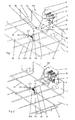
- the in the FIGS. 1 to 3 Spülguta 100 shown serves to receive tubular cleaning material 5, in particular of endoscopes. For this purpose, it is inserted into the washing compartment of a washer-disinfector. After insertion, the coupling of the endoscopes with the Spülillonkeits-, disinfecting liquid and drying air circulation of the machine via a coupling device.
- a possible construction of a cleaning and disinfecting machine and in particular the structure of a coupling device is for example from the DE 10 2007 003 894 B4 known and therefore not shown or described here.
- the FIGS. 7 and 8 only show the tightening bolt 4 of the coupling device, which will be discussed further back.
- the rinse aid carrier shown comprises a rinse basket 1, the bottom 10 and circumferential side walls 11 having a grid-like structure.
- sliders 12 are arranged, which allow movement of the basket 1 on rails, not shown, within the washing compartment.
- One of the side walls 11, in the embodiment shown the right, is provided with a recess 13. This serves to receive a connection piece 2, with the aid of which the endoscopes are connected to the coupling device.
- the endoscopes are not completely shown in the figures, only a few hose ends 5 are indicated, which are fastened to connecting pieces 20. In order to facilitate the connection of the endoscopes with the connecting pieces 20, the connector 2 can be detached from the washing basket 1, see FIG.
- the connecting piece 2 is attached to a mandrel 30, which is part of a fork-shaped receiving element, hereinafter referred to as fork 3.
- the fork 3 comprises a long guide wire 31 with the right angle bent mandrel 30, a short guide wire 32, which also has a right-angled short leg 33, a transverse strut 34 which connects the two horizontal legs of the guide wires 31 and 32, and a stop wire 35, the short Leg 33 begins extending beyond the mandrel 30.
- the fork is guided in three eyelets 36 which are attached to struts 14 and 15 of the basket bottom 10.
- a coil spring 37 is inserted through a holding lug 38 on the long guide wire 31 and fixed at its two ends by means of rotatably mounted brackets 39 to a basket strut 16.
- the distance between the two brackets 39 is designed so that the spring 37 is under pressure. It is therefore anxious to occupy one of the two indicated by dashed lines curved positions 371 or 372.
- the spring 37 produces a bistable bearing for the long guidewire 31 and over this for the entire fork 3.
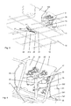
- the Figures 1 and 2 show the first 371 of the two stable layers 371 and 372, in which the mandrel 30 moved out of the recess 13 and the Spülgutliniuter is spaced from the side wall 11. This position facilitates the attachment of the connector 2 on the mandrel 30. Subsequently, the operator presses the connector 2 inwards in the in FIG. 3 illustrated second stable layer 372. In this case, the mandrel 30 pulls the connector 2 in the recess 13 and the relevant side wall 11 zoom. In this position, the connector 2 is ready for the docking operation described later.
- FIGS. 4 and 5 show the connector 2 in this position.
- the connecting piece 2 consists of a docking plate 21, a reinforcing plate 22 with a spring element 23 and the connecting piece 20.
- the docking plate 21 is bent at right angles to support shoulders 24 on the sides. It can be seen that the support shoulders 24 rest with their lower curves 241 on the stopper wire 35 so that a slight clearance between the wire 35 and the corner regions 242 adjusts behind the curves 241.
- In the upper area are the support shoulders 24 below the horizontal struts 17 and 18, which form the upper edge of the basket 1.
- these struts 17 and 18 form a stop which prevents loosening of the connector 2 from the mandrel 30 in this second stable position.
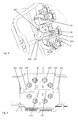
- the reinforcing plate 22 has two retaining tabs 221 and 222, which are provided with openings 223 and 224. Through these openings 223 and 224 of the mandrel 30 is inserted.
- the lower opening 224 opposite the mandrel 30 has an excess of about 1 mm, the upper opening 223 receives the mandrel 30, however, with little play.
- the two openings 223 and 224 may consist of two crosswise aligned slots.
- the connector 2 in the second stable position has game in all directions. On the one hand, it can rotate around the mandrel 30 and, depending on the direction of rotation, slide with a support shoulder 24 on the stop wire 35 into the corner region 242. On the other hand, a rotation about a horizontal axis is possible due to the game between mandrel 30 and opening 224.
- the connecting piece 2 is completed by an inserted into the reinforcing plate 22 spring element 23 and by the already described above connecting piece 20th
- FIG. 6 shows the back of the connector.
- the holes 201 for the connecting pieces 20 can be seen.
- a guide groove 25 is present, which is open at its ends v-shaped. Behind the insertion openings 251 circular extensions 252 are arranged.
- the spring element 23 is arranged behind the guide groove and has a groove 23 directed away from the recess 231, which also in FIG. 5 is recognizable.
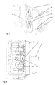
- FIGS. 7 and 8 show the docking process through which the connector 2 is pushed onto the tightening pin 4 of the coupling device during insertion of the washing basket 1 in the washing compartment.
- the head 40 of the bolt 4 is first in the extension 251 of the guide groove 25.
- the play-bearing mounting of the connector 2 ensures that the bolt 4 always finds the guide groove 25. Due to the position of the bolt 4 in relation to the connection piece 2, whose height position in the washer-disinfector is determined by the basket geometry and the position of the rails, it is achieved that the bolt 4 raises the connection piece 2 during the further travel in the groove 25 , As a result, the game and thus the mobility of the connector 2 are further increased, which is important for the later, not described here coupling process.
- the docking operation is completed when the bolt 4 rests in the recess 231 of the spring element 23. This is signaled to the operator by a reduction in the force required to insert the basket 1. Subsequently, the coupling process can be performed.
- FIGS. 9 and 10 show an alternative embodiment of a fork-shaped receiving element 300 in the first stable position (FIG. FIG. 9 ) and in the second stable position ( FIG. 10 ).
- the coil spring 37 is replaced by two leg springs 370.
- the leadership of the fork 300 takes place on the basket by two legs 302 and 303 of a U-shaped guide wire 301, which are not mounted in eyelets 36, but slide freely on the basket strut 15.
Abstract
Description
- Die Erfindung betrifft einen Spülgutträger mit einem Anschlussstück zur Aufnahme der Enden von schlauchförmigem Reinigungsgut und zur Verbindung mit einer Kupplungsvorrichtung eine den Spülgutträger aufnehmenden Spülmaschine, wobei der Spülgutträger einen Boden und mindestens eine Seitenwand besitzt, und wobei das Anschlussstück während des Spülbetriebs an der Seitenwand angeordnet ist.
- Ein Spülgutträger dieser Art ist aus der
DE 10 2007 003 894 A1 bekannt. Das Anschlussstück dient zur Ankopplung des schlauchförmigen Reinigungsguts an den Spülflüssigkeits- und Trocknungskreislauf einer Spülmaschine. Der dort beschriebene, als Korb ausgebildete Träger, ist mit einem Anschlussstück ausgestattet, welches lediglich in Richtung der Spülbehälterwand beweglich gelagert, aber ansonsten fest am Korb montiert ist. Will man das Reinigungsgut mit den am Anschlussstück vorhandenen Anschlussstutzen verbinden, muss man entweder den gesamten Korb aus der Maschine herausnehmen, oder die Verbindung bei einem im Spülbehälter der Maschine befindlichen Korb vornehmen. Dies erschwert die Handhabung. Ein weiterer Nachteil ergibt sich durch Toleranzen, welche sich korbseitig bei der Fertigung des Korbes, bei der Montage des Anschlussstücks und spülmaschinenseitig beim Aufbau der Korbführung sowie bei der Positionierung der Kupplungsvorrichtung einstellen. Die bekannte Anordnung des Anschlussstücks lässt nur einen geringen Ausgleich solcher Toleranzen zu, so dass es zu Schwierigkeiten bei der Verbindung von Anschlussstück und Kupplungsvorrichtung kommen kann. - Der Erfindung stellt sich somit das Problem, bei einem Spülgutträger der eingangs genannten Art die Handhabung zu vereinfachen und außerdem eine sichere Verbindung des Anschlussstücks mit einer Kupplungsvorrichtung zu ermöglichen.
- Erfindungsgemäß wird dieses Problem durch einen Spülgutträger mit den Merkmalen des Patentanspruchs 1 gelöst.
- Die mit der Erfindung erreichbaren Vorteile werden dadurch erreicht, dass das Anschlussstück lösbar an der Seitenwand befestigt ist. Hierdurch besteht einerseits die Möglichkeit, die notwendige Verbindung von Reinigungsgut und Anschlussstück losgelöst vom Spülgutträger vorzunehmen. Hierdurch wird die Handhabung erleichtert. Andererseits lässt diese Art der Befestigung ein gewisses Spiel zu, welches aufgrund der fertigungsbedingten Toleranzen notwendig ist, um eine sichere Verbindung des Anschlussstücks mit der Kupplungsvorrichtung zu ermöglichen.
- Vorteilhafte und zweckmäßige Ausgestaltungen und Weiterbildungen der Erfindung ergeben sich aus den nachfolgenden Unteransprüchen.
- So wird beispielsweise eine einfache Befestigung des Anschlussstücks ermöglicht, wenn dieses in der Betriebslage des Spülgutträgers in vertikaler Richtung in eine Aussparung der Seitenwand einsetzbar ist.
- Eine einfache Fertigung wird dadurch ermöglicht, dass das Anschlussstück aus Blech hergestellt ist.
- In einer besonders vorteilhaften Ausführungsform besitzt das Anschlussstück mindestens eine Haltelasche mit einer Öffnung, welche von einem in der Aussparung angeordneten, sich in der Betriebslage des Spülgutträgers in vertikaler Richtung erstreckenden Dorn aufnehmbar ist. Hierdurch ist eine Fixierung durch einfaches Einhängen möglich. Dabei wird eine sichere Halterung erreicht, wenn eine obere Haltelasche und eine untere Haltelasche vorgesehen sind, wobei mindestens eine der Öffnungen, vorzugsweise die in der unteren Haltelasche, den Dorn mit Spiel aufnimmt.
- Zum weiteren Toleranzausgleich besitzt das Anschlussstück zwei rechtwinklig abgebogene Auflageschultern, welche auf einem Anschlag lagerbar sind.
- Eine weitere Vereinfachung der Fertigung wird dadurch erreicht, dass der Dorn und der Anschlag Bestandteil eines gabelförmigen Aufnahmeelements sind. Ein solches Element kann am Boden des Spülgutträgers gehaltert sein. Außerdem ist es besonders vorteilhaft, wenn die Halterung des Aufnahmeelements bistabil ausgebildet ist, wobei in einer ersten stabilen Lage der Dorn zum Spülgutträgeräußeren von der Seitenwand beabstandet ist und in einer zweiten stabilen Lage der Dorn das Anschlussstück an die Seitenwand heranzieht. Hierdurch wird die Befestigung des Anschlussstücks am Spülgutträger vereinfacht. In der ersten stabilen Lage können die Auflageschultern auf dem Anschlag aufliegen.
- Es ist zweckmäßig, wenn das Anschlussstück eine Führungsnut zur Aufnahme eines Anzugbolzens aufweist. Zur weiteren Vereinfachung des Kupplungsvorgangs ist es außerdem vorteilhaft, wenn die Führungsnut mit mindestens einer Erweiterung zur Aufnahme einer Positionierhilfe ausgestattet ist. Nachdem die Führungsnut den Anzugbolzen aufgenommen hat, muss zur Herstellung der Kupplung eine definierte Position zwischen Bolzen und Anschlussstück hergestellt werden. Dies wird dadurch erleichtert, dass das Anschlussstück auf der zum Träger gerichteten Seite ein Federelement zur Fixierung des Anzugbolzens besitzt.
- Ausführungsbeispiele der Erfindung sind in den Zeichnungen rein schematisch dargestellt und werden nachfolgend näher beschrieben. Es zeigen
- Figur 1
- einen Spülgutträger und ein dazugehöriges Anschlussstück in perspektivischer Darstellung;
- Figur 2
- den Spülgutträger mit auf den Dorn aufgestecktem Anschlussstück und dem Aufnahmeelement in einer ersten stabilen Lage;
- Figur 3
- den Spülgutträger mit auf den Dorn aufgestecktem Anschlussstück und dem Aufnahmeelement in einer zweiten stabilen Lage;
- Figuren 4 bis 6
- das Anschlussstück in verschiedenen vergrößerten Ansichten;
- Figur 7
- das Anschlussstück mit dem Anzugbolzen zu Beginn des Andockvorgangs;
- Figur 8
- das Anschlussstück mit dem Anzugbolzen bei eingeschobenem Spülgutträger;
- Figuren 9 und 10
- einen Spülgutträger mit einer weiteren Variante eines Aufnahmeelements in der ersten und zweiten stabilen Lage.
- Der in den
Figuren 1 bis 3 dargestellte Spülgutträger 100 dient zur Aufnahme von schlauchförmigem Reinigungsgut 5, insbesondere von Endoskopen. Hierzu wird er in den Spülraum eines Reinigungs- und Desinfektionsautomaten eingeschoben. Nach dem Einschieben erfolgt die Kopplung der Endoskope mit dem Spülflüssigkeits-, Desinfektionsflüssigkeits- und Trocknungsluftkreislauf des Automaten über eine Kupplungsvorrichtung. - Ein möglicher Aufbau eines Reinigungs- und Desinfektionsautomaten und insbesondere der Aufbau einer Kupplungsvorrichtung ist beispielsweise aus der
DE 10 2007 003 894 B4 bekannt und deswegen hier nicht näher dargestellt oder beschrieben. DieFiguren 7 und 8 zeigen lediglich den Anzugbolzen 4 der Kupplungseinrichtung, auf den weiter hinten eingegangen wird. - Der dargestellte Spülgutträger umfasst einen Spülkorb 1, dessen Boden 10 und umlaufende Seitenwände 11 eine gitterartige Struktur besitzen. Im Bodenbereich sind Gleitstücke 12 angeordnet, welche eine Bewegung des Korbs 1 auf nicht dargestellten Schienen innerhalb des Spülraums ermöglichen. Einer der Seitenwände 11, im gezeigten Ausführungsbeispiel die rechte, ist mit einer Aussparung 13 versehen. Diese dient zur Aufnahme eines Anschlussstücks 2, mit dessen Hilfe die Endoskope mit der Kupplungsvorrichtung verbunden werden. Die Endoskope sind in den Figuren nicht vollständig dargestellt, es sind lediglich einige Schlauchenden 5 angedeutet, die an Anschlussstutzen 20 befestigt werden. Um die Verbindung der Endoskope mit den Anschlussstutzen 20 zu erleichtern, kann das Anschlussstück 2 vom Spülkorb 1 gelöst werden, siehe
Figur 1 . Nach der Bestückung mit den Endoskopen wird das Anschlussstück 2 auf einen Dorn 30 aufgesteckt, der Bestandteil eines gabelförmigen Aufnahmeelements ist, im Folgenden als Gabel 3 bezeichnet. Die Gabel 3 umfasst einen langen Führungsdraht 31 mit dem rechtwinklig abgebogenen Dorn 30, einen kurzen Führungsdraht 32, welcher einen ebenfalls rechtwinkligen kurzen Schenkel 33 besitzt, eine Querstrebe 34, die die beiden waagerechten Schenkel der Führungsdrähte 31 und 32 verbindet, und einen Anschlagdraht 35, der am kurzen Schenkel 33 beginnend sich über den Dorn 30 hinaus erstreckt. Die Gabel ist in drei Ösen 36 geführt, welche an Streben 14 und 15 des Korbbodens 10 befestigt sind. Des Weiteren ist eine Schraubenfeder 37 durch eine Halteöse 38 an dem langen Führungsdraht 31 gesteckt und an ihren beiden Enden mittels drehbar gelagerter Halterungen 39 an einer Korbstrebe 16 fixiert. Der Abstand der beiden Halterungen 39 ist so ausgelegt, dass die Feder 37 unter Druck steht. Sie ist deshalb bestrebt, eine der beiden gestrichelt angedeuteten gekrümmten Positionen 371 oder 372 einzunehmen. Somit erzeugt die Feder 37 für den langen Führungsdraht 31 und hierüber für die gesamte Gabel 3 eine bistabile Lagerung. - Die
Figuren 1 und 2 zeigen die erste 371 der beiden stabilen Lagen 371 und 372, bei der der Dorn 30 aus der Aussparung 13 herausgefahren und zum Spülgutträgeräußeren von der Seitenwand 11 beabstandet ist. Diese Position erleichtert die Befestigung des Anschlussstücks 2 am Dorn 30. Anschließend drückt der Bediener das Anschlussstück 2 nach innen in die in der inFigur 3 dargestellten zweiten stabilen Lage 372. Dabei zieht der Dorn 30 das Anschlussstück 2 in die Aussparung 13 und an die betreffende Seitenwand 11 heran. In dieser Position ist das Anschlussstück 2 bereit für den später beschriebenen Andockvorgang. - Die vergrößerten Darstellungen in den
Figuren 4 und5 zeigen das Anschlussstück 2 in dieser Position. Es ist erkennbar, dass das Anschlussstück 2 aus einer Andockplatte 21, einem Verstärkungsblech 22 mit einem Federelement 23 und den Anschlussstutzen 20 besteht. Die Andockplatte 21 ist an den Seiten rechtwinklig zu Auflageschultern 24 abgebogen. Es ist erkennbar, dass die Auflageschultern 24 mit ihren unteren Rundungen 241 so auf dem Anschlagdraht 35 aufliegen, dass sich ein geringes Spiel zwischen dem Draht 35 und den Eckbereichen 242 hinter den Rundungen 241 einstellt. Im oberen Bereich befinden sich die Auflageschultern 24 unter den waagerechten Streben 17 und 18, die den oberen Rand des Korbs 1 bilden. Damit bilden auch diese Streben 17 und 18 einen Anschlag, der ein Lösen des Anschlussstücks 2 vom Dorn 30 in dieser zweiten stabilen Lage verhindert. - Das Verstärkungsblech 22 besitzt zwei Haltelaschen 221 und 222, welche mit Öffnungen 223 und 224 versehen sind. Durch diese Öffnungen 223 und 224 wird der Dorn 30 gesteckt. In der
Figur 5 ist erkennbar, dass die untere Öffnung 224 gegenüber dem Dorn 30 ein Übermaß von ca. 1 mm besitzt, die obere Öffnung 223 nimmt den Dorn 30 dagegen nur mit geringem Spiel auf. Alternativ können die beiden Öffnungen 223 und 224 aus zwei kreuzweise ausgerichteten Langlöchern bestehen. Es ist erkennbar, dass das Anschlussstück 2 in der zweiten stabilen Lage Spiel in alle Richtungen hat. Es kann sich einerseits um den Dorn 30 drehen und dabei je nach Drehrichtung mit einer Auflageschulter 24 auf dem Anschlagdraht 35 bis in den Eckbereich 242 gleiten. Andererseits ist aufgrund des Spiels zwischen Dorn 30 und Öffnung 224 auch eine Drehung um eine waagerechte Achse möglich. Das Anschlussstück 2 wird komplettiert durch ein in das Verstärkungsblech 22 eingelegtes Federelement 23 und durch die bereits vorbeschriebenen Anschlussstutzen 20. -
Figur 6 zeigt die Rückseite des Anschlussstücks. Dort sind die Bohrungen 201 für die Anschlussstutzen 20 erkennbar. Außerdem ist eine Führungsnut 25 vorhanden, welche an ihren Enden v-förmig geöffnet ist. Hinter den Einführöffnungen 251 sind kreisförmige Erweiterungen 252 angeordnet. Das Federelement 23 ist hinter der Führungsnut angeordnet und besitzt eine von der Nut 25 weggerichtete Vertiefung 231, die auch inFigur 5 erkennbar ist. - Die
Figuren 7 und 8 zeigen den Andockvorgang, durch den beim Einschieben des Spülkorbs 1 in den Spülraum das Anschlussstück 2 auf den Anzugbolzen 4 der Kupplungsvorrichtung geschoben wird. Dabei gerät der Kopf 40 des Bolzens 4 zunächst in die Erweiterung 251 der Führungsnut 25. Die spielbehaftete Lagerung des Anschlussstücks 2 stellt sicher, dass der Bolzen 4 immer die Führungsnut 25 findet. Durch die Lage des Bolzens 4 im Bezug zum Anschlussstück 2, dessen Höhenposition in dem Reinigungs- und Desinfektionsautomaten von der Korbgeometrie und von der Lage der Schienen bestimmt ist, wird erreicht, dass der Bolzen 4 beim weiteren Weg in der Nut 25 das Anschlussstück 2 anhebt. Dadurch werden das Spiel und damit die Beweglichkeit des Anschlussstücks 2 weiter vergrößert, was für den späteren, hier nicht beschriebenen Kupplungsvorgang wichtig ist. Der Andockvorgang ist beendet, wenn der Bolzen 4 in der Vertiefung 231 des Federelements 23 ruht. Dies wird dem Bediener durch eine Verringerung des Kraftaufwands signalisiert, der zum Einschieben des Korbs 1 notwendig ist. Anschließend kann der Kupplungsvorgang durchgeführt werden. - Die
Figuren 9 und 10 zeigen eine alternative Ausführungsform eines gabelförmigen Aufnahmeelements 300 in der ersten stabilen Lage (Figur 9 ) und in der zweiten stabilen Lage (Figur 10 ). Hier wird die Schraubenfeder 37 durch zwei Schenkelfedern 370 ersetzt. Außerdem erfolgt die Führung der Gabel 300 am Korb durch zwei Schenkel 302 und 303 eines u-förmigen Führungsdrahts 301, die nicht in Ösen 36 gelagert sind, sondern frei an der Korbstrebe 15 gleiten.
Claims (13)
- Spülgutträger (100) mit einem Anschlussstück (2) zur Aufnahme der Enden von schlauchförmigem Reinigungsgut (5) und zur Verbindung mit einer Kupplungsvorrichtung einer den Spülgutträger (100) aufnehmenden Spülmaschine, wobei der Spülgutträger (100) einen Boden (10) und mindestens eine Seitenwand (11) besitzt, und wobei das Anschlussstück (2) während des Spülbetriebs an der Seitenwand (11) angeordnet ist,
dadurch gekennzeichnet,
dass das Anschlussstück (2) lösbar an der Seitenwand (11) befestigt ist. - Spülgutträger (100) nach Anspruch 1,
dadurch gekennzeichnet,
dass das Anschlussstück (2) in der Betriebslage des Spülgutträgers (100) in vertikaler Richtung in eine Aussparung (13) der Seitenwand (11) einsetzbar ist. - Spülgutträger (100) nach einem der Ansprüche 1 oder 2,
dadurch gekennzeichnet,
dass das Anschlussstück (2) aus Blech hergestellt ist. - Spülgutträger (100) nach Anspruch 3,
dadurch gekennzeichnet,
dass das Anschlussstück (2) mindestens eine Haltelasche (221, 222) mit einer Öffnung (223, 224) besitzt, welche von einem in der Aussparung (13) angeordneten, sich in der Betriebslage des Spülgutträgers (100) in vertikaler Richtung erstreckenden Dorn (30) aufnehmbar ist. - Spülgutträger (100) nach Anspruch 4,
gekennzeichnet durch eine obere Haltelasche (221) und eine untere Haltelasche (222), wobei mindestens eine der Öffnungen (223, 224), vorzugsweise die Öffnung (224) in der unteren Haltelasche (222), den Dorn (30) mit Spiel aufnimmt. - Spülgutträger (100) nach mindestens einem der Ansprüche 3 bis 5,
dadurch gekennzeichnet,
dass das Anschlussstück (2) zwei rechtwinklig abgebogene Auflageschultern (24) besitzt, welche auf einem Anschlag (35) lagerbar sind. - Spülgutträger (100) nach einem der Ansprüche 3 bis 6,
dadurch gekennzeichnet,
dass der Dorn (30) und der Anschlag (35) Bestandteil eines gabelförmigen Aufnahmeelements (3) sind. - Spülgutträger (100) nach Anspruch 7,
dadurch gekennzeichnet,
dass das Aufnahmeelement (3) am Boden (10) des Spülgutträgers (100) gehaltert ist. - Spülgutträger (100) nach Anspruch 8,
dadurch gekennzeichnet,
dass die Halterung des Aufnahmeelements (3) bistabil ausgebildet ist, wobei in einer ersten stabilen Lage der Dorn (30) zum Spülgutträgeräußeren von der Seitenwand (11) beabstandet ist und in einer zweiten stabilen Lage der Dorn (30) das Anschlussstück (2) an die Seitenwand (11) heranzieht. - Spülgutträger (100) nach mindestens einem der Ansprüche 5 bis 9,
dadurch gekennzeichnet,
dass in der ersten stabilen Lage die Auflageschultern (24) auf dem Anschlag (35) aufliegen. - Spülgutträger (100) nach mindestens einem der Ansprüche 1 bis 10,
dadurch gekennzeichnet,
dass das Anschlussstück (2) eine Führungsnut (25) zur Aufnahme eines Anzugbolzens (4) der Kupplungsvorrichtung aufweist. - Spülgutträger (100) nach Anspruch 11,
dadurch gekennzeichnet,
dass die Führungsnut (25) mit mindestens einer Erweiterung (252) zur Aufnahme einer Positionierhilfe ausgestattet ist. - Spülgutträger (100) nach einem der Ansprüche 11 oder 12,
dadurch gekennzeichnet,
dass das Anschlussstück (2) auf der zum Spülgutträger (100) gerichteten Seite ein Federelement (23) zur Fixierung des Anzugbolzens (4) besitzt.
Applications Claiming Priority (1)
| Application Number | Priority Date | Filing Date | Title |
|---|---|---|---|
| DE102008062760A DE102008062760A1 (de) | 2008-12-18 | 2008-12-18 | Spülgutträger mit einem Anschlussstück für schlauchförmiges Reinigungsgut |
Publications (2)
| Publication Number | Publication Date |
|---|---|
| EP2201886A1 true EP2201886A1 (de) | 2010-06-30 |
| EP2201886B1 EP2201886B1 (de) | 2013-03-20 |
Family
ID=41818799
Family Applications (1)
| Application Number | Title | Priority Date | Filing Date |
|---|---|---|---|
| EP09401039A Active EP2201886B1 (de) | 2008-12-18 | 2009-11-16 | Spülgutträger mit einem Anschlussstück für schlauchförmiges Reinigungsgut |
Country Status (2)
| Country | Link |
|---|---|
| EP (1) | EP2201886B1 (de) |
| DE (1) | DE102008062760A1 (de) |
Cited By (2)
| Publication number | Priority date | Publication date | Assignee | Title |
|---|---|---|---|---|
| EP3034029A1 (de) | 2014-12-18 | 2016-06-22 | Miele & Cie. KG | Spülgutträger sowie spülmaschine mit einem solchen spülgutträger |
| DE102018111693B3 (de) | 2018-05-16 | 2019-07-18 | Miele & Cie. Kg | Kopplungsvorrichtung zum mechanischen und hydraulischen Koppeln eines Spülguts mit einem Reinigungsgerät, Spülgutträger und Reinigungsgerät mit einer Kopplungsvorrichtung |
Families Citing this family (1)
| Publication number | Priority date | Publication date | Assignee | Title |
|---|---|---|---|---|
| DE102018116115A1 (de) | 2017-07-12 | 2019-01-17 | Miele & Cie. Kg | Korbverriegelungsvorrichtung für einen Spülkorb zum Verriegeln des Spülkorbs in einer Spülmaschine, Spülkorbvorrichtung mit einer Korbverriegelungsvorrichtung, Spülmaschine mit einer Rastnase und Verfahren zum Verriegeln eines Spülkorbs in einer Spülmaschine |
Citations (4)
| Publication number | Priority date | Publication date | Assignee | Title |
|---|---|---|---|---|
| DE3413386A1 (de) * | 1984-04-10 | 1985-10-17 | Miele & Cie GmbH & Co, 4830 Gütersloh | Spuelmaschine zum reinigen, desinfizieren und trocknen von medizinischem zubehoer |
| EP0483059A1 (de) * | 1990-10-23 | 1992-04-29 | Hamo Ag | Maschine zum Reinigen von schlauchfoermigen Artikeln |
| EP1266604A2 (de) * | 2001-06-09 | 2002-12-18 | Lg Electronics Inc. | Einrichtung zur Reinigung von medizinischen Geräten |
| EP1946692A2 (de) * | 2007-01-19 | 2008-07-23 | Miele & Cie. KG | Spülmaschine und Spülgutträger mit einer Kupplungsvorrichtung zur Einleitung von Spül- und oder Desinfektionsflüssigkeit und/oder Trocknungsluft |
Family Cites Families (2)
| Publication number | Priority date | Publication date | Assignee | Title |
|---|---|---|---|---|
| DE4323816C2 (de) * | 1993-07-15 | 1996-02-08 | Siemens Ag | Verfahren und Vorrichtung zur Intensivreinigung von ärztlichen, insbesondere zahnärztlichen, Gegenständen |
| ATE483395T1 (de) * | 2007-07-04 | 2010-10-15 | Arcelik As | Geschirrspüler mit flexibler sprüharmzuführleitung |
-
2008
- 2008-12-18 DE DE102008062760A patent/DE102008062760A1/de not_active Withdrawn
-
2009
- 2009-11-16 EP EP09401039A patent/EP2201886B1/de active Active
Patent Citations (4)
| Publication number | Priority date | Publication date | Assignee | Title |
|---|---|---|---|---|
| DE3413386A1 (de) * | 1984-04-10 | 1985-10-17 | Miele & Cie GmbH & Co, 4830 Gütersloh | Spuelmaschine zum reinigen, desinfizieren und trocknen von medizinischem zubehoer |
| EP0483059A1 (de) * | 1990-10-23 | 1992-04-29 | Hamo Ag | Maschine zum Reinigen von schlauchfoermigen Artikeln |
| EP1266604A2 (de) * | 2001-06-09 | 2002-12-18 | Lg Electronics Inc. | Einrichtung zur Reinigung von medizinischen Geräten |
| EP1946692A2 (de) * | 2007-01-19 | 2008-07-23 | Miele & Cie. KG | Spülmaschine und Spülgutträger mit einer Kupplungsvorrichtung zur Einleitung von Spül- und oder Desinfektionsflüssigkeit und/oder Trocknungsluft |
Cited By (4)
| Publication number | Priority date | Publication date | Assignee | Title |
|---|---|---|---|---|
| EP3034029A1 (de) | 2014-12-18 | 2016-06-22 | Miele & Cie. KG | Spülgutträger sowie spülmaschine mit einem solchen spülgutträger |
| DE102014119105A1 (de) | 2014-12-18 | 2016-06-23 | Miele & Cie. Kg | Spülgutträger sowie Spülmaschine mit einem solchen Spülgutträger |
| DE102018111693B3 (de) | 2018-05-16 | 2019-07-18 | Miele & Cie. Kg | Kopplungsvorrichtung zum mechanischen und hydraulischen Koppeln eines Spülguts mit einem Reinigungsgerät, Spülgutträger und Reinigungsgerät mit einer Kopplungsvorrichtung |
| EP3586788A1 (de) | 2018-05-16 | 2020-01-01 | Miele & Cie. KG | Kopplungsvorrichtung zum mechanischen und hydraulischen koppeln eines spülguts mit einem reinigungsgerät, spülgutträger und reinigungsgerät mit einer kopplungsvorrichtung |
Also Published As
| Publication number | Publication date |
|---|---|
| EP2201886B1 (de) | 2013-03-20 |
| DE102008062760A1 (de) | 2010-07-01 |
Similar Documents
| Publication | Publication Date | Title |
|---|---|---|
| DE69915527T2 (de) | Staubsauger | |
| DE102012106947A1 (de) | Wischblatt zum Reinigen von Fahrzeugscheiben | |
| EP2227583A1 (de) | Reinigungsvorrichtung für ein mit flusen beladenes bauteil in einem hausgerät sowie hausgerät und verfahren zum reinigen eines mit flusen beladenen bauteils | |
| EP2106236B1 (de) | Korbführungsschiene für eine geschirrspülmaschine | |
| DE2410733A1 (de) | Scheibenwaschanlage | |
| DE102011007247A1 (de) | Wischblattadaptervorrichtung | |
| DE102006055349B3 (de) | Trägermechanismus für einen Geschirrkorb | |
| EP2201886B1 (de) | Spülgutträger mit einem Anschlussstück für schlauchförmiges Reinigungsgut | |
| DE19926962B4 (de) | Geschirrspülmaschine mit höhenverstellbarem Korb | |
| DE10332149B3 (de) | Einsatzwagen für Spülgut | |
| EP2677917A1 (de) | Wischgerät | |
| EP2949253B1 (de) | SAUGFUß FÜR EINE BODENREINIGUNGSMASCHINE | |
| DE102010048956A1 (de) | Vorrichtung und Verfahren zur Befestigung eines mindestens eine Öffnung aufweisenden Bauteils an einem Trägerteil | |
| EP3047785B1 (de) | Geschirrspülmaschine, insbesondere haushaltsgeschirrspülmaschine | |
| DE102019129347A1 (de) | Anhängekupplung | |
| EP3991627B1 (de) | Vorrichtung zum übertragen eines drehmoments mit einer antreibbaren welle für eine geschirrspülmaschine sowie spülarm für eine geschirrspülmaschine | |
| DE102022202344A1 (de) | Zur Montage in der Nähe einer Wandfläche geeignetes Haushaltsgerät | |
| DE102014110397A1 (de) | Spülarmanordnung für eine programmgesteuerte Spülmaschine | |
| DE102006055348B4 (de) | Geschirrspülmaschine | |
| EP2271246A1 (de) | Geschirrkorb und geschirrspülmaschine | |
| DE102015106664A1 (de) | Filterbefestigungssystem für Staubsauger sowie Filtereinheit für ein solches Filterbefestigungssystem | |
| EP1463609B1 (de) | Bodenreinigungsgerät | |
| EP4151324A1 (de) | Aufnahmevorrichtung zum aufnehmen mindestens eines schlauchs für ein reinigungsgerät und reinigungsgerät | |
| DE202009009911U1 (de) | Vorrichtung für ein wasserführendes Hausgerät sowie wasserführendes Hausgerät, insbesondere Waschmaschine oder Waschtrockner, mit einer derartigen Vorrichtung | |
| EP0480360A2 (de) | Warnleuchte für Fahrzeuge |
Legal Events
| Date | Code | Title | Description |
|---|---|---|---|
| PUAI | Public reference made under article 153(3) epc to a published international application that has entered the european phase |
Free format text: ORIGINAL CODE: 0009012 |
|
| 17P | Request for examination filed |
Effective date: 20100330 |
|
| AK | Designated contracting states |
Kind code of ref document: A1 Designated state(s): AT BE BG CH CY CZ DE DK EE ES FI FR GB GR HR HU IE IS IT LI LT LU LV MC MK MT NL NO PL PT RO SE SI SK SM TR |
|
| AX | Request for extension of the european patent |
Extension state: AL BA RS |
|
| 17Q | First examination report despatched |
Effective date: 20111223 |
|
| REG | Reference to a national code |
Ref country code: DE Ref legal event code: R079 Ref document number: 502009006562 Country of ref document: DE Free format text: PREVIOUS MAIN CLASS: A47L0015500000 Ipc: A61B0019000000 |
|
| RIC1 | Information provided on ipc code assigned before grant |
Ipc: A61B 19/00 20060101AFI20121012BHEP Ipc: A47L 15/00 20060101ALN20121012BHEP |
|
| GRAP | Despatch of communication of intention to grant a patent |
Free format text: ORIGINAL CODE: EPIDOSNIGR1 |
|
| RIC1 | Information provided on ipc code assigned before grant |
Ipc: A47L 15/00 20060101ALN20121029BHEP Ipc: A61B 19/00 20060101AFI20121029BHEP |
|
| RIC1 | Information provided on ipc code assigned before grant |
Ipc: A47L 15/00 20060101ALN20121107BHEP Ipc: A61B 19/00 20060101AFI20121107BHEP |
|
| GRAS | Grant fee paid |
Free format text: ORIGINAL CODE: EPIDOSNIGR3 |
|
| GRAA | (expected) grant |
Free format text: ORIGINAL CODE: 0009210 |
|
| AK | Designated contracting states |
Kind code of ref document: B1 Designated state(s): AT BE BG CH CY CZ DE DK EE ES FI FR GB GR HR HU IE IS IT LI LT LU LV MC MK MT NL NO PL PT RO SE SI SK SM TR |
|
| REG | Reference to a national code |
Ref country code: GB Ref legal event code: FG4D Free format text: NOT ENGLISH |
|
| REG | Reference to a national code |
Ref country code: CH Ref legal event code: EP |
|
| REG | Reference to a national code |
Ref country code: IE Ref legal event code: FG4D Free format text: LANGUAGE OF EP DOCUMENT: GERMAN |
|
| REG | Reference to a national code |
Ref country code: AT Ref legal event code: REF Ref document number: 601557 Country of ref document: AT Kind code of ref document: T Effective date: 20130415 |
|
| REG | Reference to a national code |
Ref country code: CH Ref legal event code: NV Representative=s name: FIAMMENGHI-FIAMMENGHI, CH |
|
| REG | Reference to a national code |
Ref country code: DE Ref legal event code: R096 Ref document number: 502009006562 Country of ref document: DE Effective date: 20130516 |
|
| REG | Reference to a national code |
Ref country code: NL Ref legal event code: T3 |
|
| PG25 | Lapsed in a contracting state [announced via postgrant information from national office to epo] |
Ref country code: BG Free format text: LAPSE BECAUSE OF FAILURE TO SUBMIT A TRANSLATION OF THE DESCRIPTION OR TO PAY THE FEE WITHIN THE PRESCRIBED TIME-LIMIT Effective date: 20130620 Ref country code: NO Free format text: LAPSE BECAUSE OF FAILURE TO SUBMIT A TRANSLATION OF THE DESCRIPTION OR TO PAY THE FEE WITHIN THE PRESCRIBED TIME-LIMIT Effective date: 20130620 Ref country code: SE Free format text: LAPSE BECAUSE OF FAILURE TO SUBMIT A TRANSLATION OF THE DESCRIPTION OR TO PAY THE FEE WITHIN THE PRESCRIBED TIME-LIMIT Effective date: 20130320 Ref country code: LT Free format text: LAPSE BECAUSE OF FAILURE TO SUBMIT A TRANSLATION OF THE DESCRIPTION OR TO PAY THE FEE WITHIN THE PRESCRIBED TIME-LIMIT Effective date: 20130320 Ref country code: ES Free format text: LAPSE BECAUSE OF FAILURE TO SUBMIT A TRANSLATION OF THE DESCRIPTION OR TO PAY THE FEE WITHIN THE PRESCRIBED TIME-LIMIT Effective date: 20130701 |
|
| REG | Reference to a national code |
Ref country code: LT Ref legal event code: MG4D |
|
| PG25 | Lapsed in a contracting state [announced via postgrant information from national office to epo] |
Ref country code: SI Free format text: LAPSE BECAUSE OF FAILURE TO SUBMIT A TRANSLATION OF THE DESCRIPTION OR TO PAY THE FEE WITHIN THE PRESCRIBED TIME-LIMIT Effective date: 20130320 Ref country code: LV Free format text: LAPSE BECAUSE OF FAILURE TO SUBMIT A TRANSLATION OF THE DESCRIPTION OR TO PAY THE FEE WITHIN THE PRESCRIBED TIME-LIMIT Effective date: 20130320 Ref country code: GR Free format text: LAPSE BECAUSE OF FAILURE TO SUBMIT A TRANSLATION OF THE DESCRIPTION OR TO PAY THE FEE WITHIN THE PRESCRIBED TIME-LIMIT Effective date: 20130621 Ref country code: FI Free format text: LAPSE BECAUSE OF FAILURE TO SUBMIT A TRANSLATION OF THE DESCRIPTION OR TO PAY THE FEE WITHIN THE PRESCRIBED TIME-LIMIT Effective date: 20130320 |
|
| PG25 | Lapsed in a contracting state [announced via postgrant information from national office to epo] |
Ref country code: HR Free format text: LAPSE BECAUSE OF FAILURE TO SUBMIT A TRANSLATION OF THE DESCRIPTION OR TO PAY THE FEE WITHIN THE PRESCRIBED TIME-LIMIT Effective date: 20130320 |
|
| PG25 | Lapsed in a contracting state [announced via postgrant information from national office to epo] |
Ref country code: EE Free format text: LAPSE BECAUSE OF FAILURE TO SUBMIT A TRANSLATION OF THE DESCRIPTION OR TO PAY THE FEE WITHIN THE PRESCRIBED TIME-LIMIT Effective date: 20130320 Ref country code: SK Free format text: LAPSE BECAUSE OF FAILURE TO SUBMIT A TRANSLATION OF THE DESCRIPTION OR TO PAY THE FEE WITHIN THE PRESCRIBED TIME-LIMIT Effective date: 20130320 Ref country code: RO Free format text: LAPSE BECAUSE OF FAILURE TO SUBMIT A TRANSLATION OF THE DESCRIPTION OR TO PAY THE FEE WITHIN THE PRESCRIBED TIME-LIMIT Effective date: 20130320 Ref country code: PT Free format text: LAPSE BECAUSE OF FAILURE TO SUBMIT A TRANSLATION OF THE DESCRIPTION OR TO PAY THE FEE WITHIN THE PRESCRIBED TIME-LIMIT Effective date: 20130722 Ref country code: IS Free format text: LAPSE BECAUSE OF FAILURE TO SUBMIT A TRANSLATION OF THE DESCRIPTION OR TO PAY THE FEE WITHIN THE PRESCRIBED TIME-LIMIT Effective date: 20130720 Ref country code: CZ Free format text: LAPSE BECAUSE OF FAILURE TO SUBMIT A TRANSLATION OF THE DESCRIPTION OR TO PAY THE FEE WITHIN THE PRESCRIBED TIME-LIMIT Effective date: 20130320 |
|
| PG25 | Lapsed in a contracting state [announced via postgrant information from national office to epo] |
Ref country code: CY Free format text: LAPSE BECAUSE OF FAILURE TO SUBMIT A TRANSLATION OF THE DESCRIPTION OR TO PAY THE FEE WITHIN THE PRESCRIBED TIME-LIMIT Effective date: 20130320 Ref country code: PL Free format text: LAPSE BECAUSE OF FAILURE TO SUBMIT A TRANSLATION OF THE DESCRIPTION OR TO PAY THE FEE WITHIN THE PRESCRIBED TIME-LIMIT Effective date: 20130320 |
|
| PLBE | No opposition filed within time limit |
Free format text: ORIGINAL CODE: 0009261 |
|
| STAA | Information on the status of an ep patent application or granted ep patent |
Free format text: STATUS: NO OPPOSITION FILED WITHIN TIME LIMIT |
|
| PG25 | Lapsed in a contracting state [announced via postgrant information from national office to epo] |
Ref country code: DK Free format text: LAPSE BECAUSE OF FAILURE TO SUBMIT A TRANSLATION OF THE DESCRIPTION OR TO PAY THE FEE WITHIN THE PRESCRIBED TIME-LIMIT Effective date: 20130320 |
|
| 26N | No opposition filed |
Effective date: 20140102 |
|
| REG | Reference to a national code |
Ref country code: DE Ref legal event code: R097 Ref document number: 502009006562 Country of ref document: DE Effective date: 20140102 |
|
| BERE | Be: lapsed |
Owner name: MIELE & CIE. K.G. Effective date: 20131130 |
|
| PG25 | Lapsed in a contracting state [announced via postgrant information from national office to epo] |
Ref country code: MC Free format text: LAPSE BECAUSE OF FAILURE TO SUBMIT A TRANSLATION OF THE DESCRIPTION OR TO PAY THE FEE WITHIN THE PRESCRIBED TIME-LIMIT Effective date: 20130320 |
|
| REG | Reference to a national code |
Ref country code: FR Ref legal event code: ST Effective date: 20140731 |
|
| REG | Reference to a national code |
Ref country code: IE Ref legal event code: MM4A |
|
| PG25 | Lapsed in a contracting state [announced via postgrant information from national office to epo] |
Ref country code: BE Free format text: LAPSE BECAUSE OF NON-PAYMENT OF DUE FEES Effective date: 20131130 |
|
| PG25 | Lapsed in a contracting state [announced via postgrant information from national office to epo] |
Ref country code: IE Free format text: LAPSE BECAUSE OF NON-PAYMENT OF DUE FEES Effective date: 20131116 |
|
| PG25 | Lapsed in a contracting state [announced via postgrant information from national office to epo] |
Ref country code: FR Free format text: LAPSE BECAUSE OF NON-PAYMENT OF DUE FEES Effective date: 20131202 |
|
| PG25 | Lapsed in a contracting state [announced via postgrant information from national office to epo] |
Ref country code: SM Free format text: LAPSE BECAUSE OF FAILURE TO SUBMIT A TRANSLATION OF THE DESCRIPTION OR TO PAY THE FEE WITHIN THE PRESCRIBED TIME-LIMIT Effective date: 20130320 |
|
| PG25 | Lapsed in a contracting state [announced via postgrant information from national office to epo] |
Ref country code: TR Free format text: LAPSE BECAUSE OF FAILURE TO SUBMIT A TRANSLATION OF THE DESCRIPTION OR TO PAY THE FEE WITHIN THE PRESCRIBED TIME-LIMIT Effective date: 20130320 |
|
| PG25 | Lapsed in a contracting state [announced via postgrant information from national office to epo] |
Ref country code: MK Free format text: LAPSE BECAUSE OF FAILURE TO SUBMIT A TRANSLATION OF THE DESCRIPTION OR TO PAY THE FEE WITHIN THE PRESCRIBED TIME-LIMIT Effective date: 20130320 Ref country code: LU Free format text: LAPSE BECAUSE OF NON-PAYMENT OF DUE FEES Effective date: 20131116 Ref country code: HU Free format text: LAPSE BECAUSE OF FAILURE TO SUBMIT A TRANSLATION OF THE DESCRIPTION OR TO PAY THE FEE WITHIN THE PRESCRIBED TIME-LIMIT; INVALID AB INITIO Effective date: 20091116 |
|
| PG25 | Lapsed in a contracting state [announced via postgrant information from national office to epo] |
Ref country code: MT Free format text: LAPSE BECAUSE OF FAILURE TO SUBMIT A TRANSLATION OF THE DESCRIPTION OR TO PAY THE FEE WITHIN THE PRESCRIBED TIME-LIMIT Effective date: 20130320 |
|
| P01 | Opt-out of the competence of the unified patent court (upc) registered |
Effective date: 20230529 |
|
| PGFP | Annual fee paid to national office [announced via postgrant information from national office to epo] |
Ref country code: NL Payment date: 20231124 Year of fee payment: 15 |
|
| PGFP | Annual fee paid to national office [announced via postgrant information from national office to epo] |
Ref country code: GB Payment date: 20231121 Year of fee payment: 15 |
|
| PGFP | Annual fee paid to national office [announced via postgrant information from national office to epo] |
Ref country code: IT Payment date: 20231124 Year of fee payment: 15 Ref country code: DE Payment date: 20231130 Year of fee payment: 15 Ref country code: CH Payment date: 20231202 Year of fee payment: 15 Ref country code: AT Payment date: 20231117 Year of fee payment: 15 |