EP2199682B1 - Gasstandherd - Google Patents
Gasstandherd Download PDFInfo
- Publication number
- EP2199682B1 EP2199682B1 EP09177323.4A EP09177323A EP2199682B1 EP 2199682 B1 EP2199682 B1 EP 2199682B1 EP 09177323 A EP09177323 A EP 09177323A EP 2199682 B1 EP2199682 B1 EP 2199682B1
- Authority
- EP
- European Patent Office
- Prior art keywords
- housing wall
- fixing element
- gas
- stand
- gas line
- Prior art date
- Legal status (The legal status is an assumption and is not a legal conclusion. Google has not performed a legal analysis and makes no representation as to the accuracy of the status listed.)
- Active
Links
Images

Classifications
-
- F—MECHANICAL ENGINEERING; LIGHTING; HEATING; WEAPONS; BLASTING
- F24—HEATING; RANGES; VENTILATING
- F24C—DOMESTIC STOVES OR RANGES ; DETAILS OF DOMESTIC STOVES OR RANGES, OF GENERAL APPLICATION
- F24C3/00—Stoves or ranges for gaseous fuels
-
- F—MECHANICAL ENGINEERING; LIGHTING; HEATING; WEAPONS; BLASTING
- F24—HEATING; RANGES; VENTILATING
- F24C—DOMESTIC STOVES OR RANGES ; DETAILS OF DOMESTIC STOVES OR RANGES, OF GENERAL APPLICATION
- F24C3/00—Stoves or ranges for gaseous fuels
- F24C3/12—Arrangement or mounting of control or safety devices
Definitions
- the invention relates to a household appliance designed as a gas range, with a rear housing wall and at least one provided in the housing wall opening through which a gas line is guided in the interior of the domestic appliance, wherein a fixing member is provided with which the gas line in the region of the opening relative to Housing wall can be fixed in at least one direction.
- a gas range according to the preamble of claim 1 is from the document EP 0 877 193 A1 known.
- Household appliances of the type mentioned are free-standing gas stoves with gas-fired cooking rings and / or with a gas-heated oven.
- Generic home appliances have a gas line whose outer end is located outside a housing of the household appliance and which serves to connect a gas supply line or a gas cylinder to the domestic appliance.
- the gas line of the household appliance is guided through an opening in a housing wall of the household appliance in the housing interior.
- the opening is usually and as for example in the document JP 3 205148 B2 disclosed, arranged in the rear wall of the housing.
- a gas consumer gas burners are usually provided in gas stoves in particular hob burners and / or oven burner.
- the gas line is inserted from above into an already mounted housing of the household appliance. This requires that the opening, which is provided for the passage of the gas line in the housing wall, must extend to the upper edge of the housing wall.
- the gas line In the final-mounted domestic appliance, however, the gas line must be fixed relative to the housing wall up to ensure that during transport and during operation of the domestic appliance, the gas line can not be unintentionally moved up or even removed from the domestic appliance.
- a separate fixing element is provided in household appliances of the prior art, which is screwed above the gas line to the housing wall.
- the present invention has for its object to provide a particularly simple design and very easy to produce generic household appliance.
- the fixing element is movably formed on the housing wall.
- the fixing element can be dispensed with as a separate component.
- the assembly is simplified in that the molded fixing element is already in the right place before assembly. After insertion of the gas line, the molded fixing element only has to be moved to an operating position and fixed in this position.
- the fixing element is integrally formed on the housing wall.
- the fixing element consists of the same material as the housing wall and is made in the manufacture of the housing wall with.
- the fixing element is movable relative to the housing wall by material deformation, preferably by plastic deformation of the material.
- the fixing In a mounting position, the fixing allows the insertion of the gas line in the domestic appliance, while in an operating position, the fixing element defines the gas line relative to the housing wall.
- the material deforms plastically in the region of the transition from the housing wall to the fixing element.
- the housing wall is formed of sheet metal.
- the molded onto the housing wall fixing is also made of sheet metal.
- Moving the fixing element relative to the housing wall is facilitated by the fact that the housing wall has a perforation in the region of the transition to the fixing element.
- the perforation reduces in particular the force required for plastic deformation of the sheet.
- the perforation defines the area intended for plastic deformation. Moving the fixing of the Deformation provided area. Moving the fixing from the mounting position to the operating position can be done manually, ie without tools.
- the gas line is arranged in the region of the opening substantially perpendicular to the housing wall.
- the fixing element has a mounting position in which the gas line is movable relative to the housing wall in at least one direction parallel to the housing wall, and an operating position in which the gas line is fixed relative to the housing wall in all directions parallel to the housing wall.
- the gas line is provided for supplying a gas hob.
- the gas line can be inserted from above into the household appliance with the fixing element located in the mounting position.
- a screw securing element for fixing the fixing in its operating position.
- the securing element fixes the fixing element in the operating position so that it can not be moved unintentionally or out of ignorance into the mounting position.
- FIG. 1 shows an inventive, executed as gas stove domestic appliance in a perspective view obliquely from behind.
- the housing of the gas range with a rear housing wall 1 and a side wall 2.
- the top of the gas range is formed by a hob plate 3, in which four openings 4 are provided for mounting gas burners.
- the gas burners are not shown in the figure.
- the rear housing wall 1 has a number of imprints 15 and punching 16, which serve for example for stiffening the housing wall 1, for receiving components in the interior of the housing or for carrying supply air or exhaust air.
- imprints 15 and punching 16 serve for example for stiffening the housing wall 1, for receiving components in the interior of the housing or for carrying supply air or exhaust air.
- an opening 5 through which the gas line 6 is guided.
- the area of the opening 5 located above the gas line 6 is closed by a fixing element 7.
- the fixing element 7 is integrally formed on the rear housing wall 1.
- the gas line 6 has outside the housing of the gas range two vertical sections, each with a threaded connection 8.
- either the left or the right threaded connection 8 can be connected to a gas supply line of the building.
- the thread connection not required for this purpose is closed by means of a sealing plug.
- the vertical sections of the gas line 6 go over into a horizontal section, which is guided through the openings 5 in the interior of the housing.
- the gas line 6 extends in a substantially U-shaped manner in the horizontal direction parallel to the hob plate 4. With gas valves which are placed on the gas line 6, the gas supply to each of the gas burners can be controlled individually.
- the fixing element 7 is in its operating position in which the gas line 6 is fixed upward.
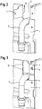
- FIG. 2 shows in detail the area of the opening 5 of the housing wall 1 with fixation element 7 located in the mounting position.
- the fixing element 7 is bent forward, so that the opening 5 extends to the upper end of the rear housing wall 1.
- the fixing element 7 is in this case substantially perpendicular to the housing wall 1.
- the gas line 6 can be used in the mounting position in the fixing position 7 in the vertical direction in the range or removed from the range cooker.
- the fixing element 7 In order to fix the gas line 6, the fixing element 7 is in the operating position according to FIG. 3 emotional. In this operating position, it can be fixed by means of a securing element 9, which is preferably designed as a screw. A movement of the gas line upwards is prevented by the fixing element 7.
- the fixing element 7 is integrally formed on the rear housing wall 1.
- the housing wall 1 and the fixing element 7 are formed by a single sheet metal part.
- the mobility of the fixing element 7 relative to the housing wall 1 is ensured by the fact that the sheet has a perforation 10 in the region of the transition between the housing wall 1 and the fixing element 7.
- the perforation 10 is executed by two elongated holes, which are produced by punching or laser cutting in the sheet metal of the housing wall 1.
Landscapes
- Engineering & Computer Science (AREA)
- Chemical & Material Sciences (AREA)
- Combustion & Propulsion (AREA)
- Mechanical Engineering (AREA)
- General Engineering & Computer Science (AREA)
- Feeding And Controlling Fuel (AREA)
Description
- Die Erfindung betrifft ein als Gasstandherd ausgeführtes Hausgerät, mit einer rückseitigen Gehäusewand und mindestens einer in der Gehäusewand vorgesehenen Öffnung, durch die eine Gasleitung in das Innere des Hausgeräts geführt ist, wobei ein Fixierelement vorgesehen ist, mit dem die Gasleitung im Bereich der Öffnung relativ zur Gehäusewand in mindestens einer Richtung festlegbar ist.
- Ein Gasstandherd gemäß dem Oberbegriff des Anspruchs 1 ist aus der Druckschrift
EP 0 877 193 A1 bekannt. - Bei Hausgeräten der genannten Art handelt es sich um frei stehende Gasherde mit gasbeheizten Kochstellen und/oder mit einem gasbeheizten Backofen. Gattungsgemäße Hausgeräte besitzen eine Gasleitung, deren äußeres Ende sich außerhalb eines Gehäuses des Hausgeräts befindet und welches dazu dient, eine Gasversorgungsleitung oder eine Gasflasche an das Hausgerät anzuschließen. Die Gasleitung des Hausgeräts ist durch eine Öffnung in einer Gehäusewand des Hausgeräts in das Gehäuseinnere geführt. Dabei ist die Öffnung in der Regel und wie beispielsweise in der Druckschrift
JP 3 205148 B2 - Bei der Montage des aus der Druckschrift
EP 0 877 193 A1 bekannten Hausgeräts wird die Gasleitung von oben in ein bereits montiertes Gehäuse des Hausgeräts eingesetzt. Dies erfordert, dass die Öffnung, die zur Durchführung der Gasleitung in der Gehäusewand vorgesehen ist, sich bis zur Oberkante der Gehäusewand erstrecken muss. - Bei dem endmontierten Hausgerät hingegen muss die Gasleitung relativ zur Gehäusewand nach oben fixiert sein, um sicher zu stellen, dass während des Transports und während des Betriebs des Hausgeräts die Gasleitung nicht unbeabsichtigt nach oben bewegt oder sogar aus dem Hausgerät entfernt werden kann. Hierzu ist bei Hausgeräten des Standes der Technik ein separates Fixierelement vorgesehen, das oberhalb der Gasleitung an die Gehäusewand geschraubt wird.
- Der vorliegenden Erfindung liegt die Aufgabe zugrunde, ein besonders einfach aufgebautes und besonders einfach herstellbares gattungsgemäßes Hausgerät zur Verfügung zu stellen.
- Diese Aufgabe wird durch einen Gasstandherd mit den im Anspruch 1 angegebenen Merkmalen gelöst.
- Erfindungsgemäß ist das Fixierelement bewegbar an die Gehäusewand angeformt ist. Durch das Anformen des Fixierelements an die Gehäusewand kann auf das Fixierelement als separates Bauteil verzichtet werden. Die Montage wird dadurch vereinfacht, dass sich das angeformte Fixierelement bereits vor der Montage an der richtigen Stelle befindet. Nach dem Einsetzen der Gasleitung muss das angeformte Fixierelement nur noch in eine Betriebsposition bewegt und in dieser fixiert werden.
- Bevorzugt ist das Fixierelement einstückig an die Gehäusewand angeformt. Das Fixierelement besteht dabei aus demselben Material wie die Gehäusewand und wird bei der Herstellung der Gehäusewand mit gefertigt.
- Das Fixierelement ist durch Materialverformung, vorzugsweise durch plastische Materialverformung, relativ zur Gehäusewand bewegbar. In einer Montageposition ermöglicht das Fixierelement das Einsetzen der Gasleitung in das Hausgerät, während in einer Betriebsposition das Fixierelement die Gasleitung relativ zur Gehäusewand festlegt. Während des Bewegens des Fixierelements zwischen der Betriebsposition und der Montageposition verformt sich das Material im Bereich des Übergangs von der Gehäusewand auf das Fixierelement plastisch.
- Mit besonderem Vorteil ist die Gehäusewand aus Blech ausgebildet. Das an die Gehäusewand angeformte Fixierelement ist ebenfalls aus Blech ausgeführt.
- Ein Bewegen des Fixierelements relativ zur Gehäusewand wird dadurch erleichtert, dass die Gehäusewand im Bereich des Übergangs zum Fixierelement eine Perforierung aufweist. Die Perforierung vermindert insbesondere die zur plastischen Verformung des Blechs erforderliche Kraft. Darüber hinaus definiert die Perforierung den für die plastische Verformung vorgesehenen Bereich. Das Bewegen des Fixierelements von der Verformung vorgesehenen Bereich. Das Bewegen des Fixierelements von der Montageposition in die Betriebsposition kann dadurch manuell, d.h. ohne Werkzeuge erfolgen.
- Die Gasleitung ist im Bereich der Öffnung im Wesentlichen senkrecht zur Gehäusewand angeordnet.
- Das Fixierelement weist eine Montageposition auf, in der die Gasleitung relativ zu der Gehäusewand in mindestens einer Richtung parallel zur Gehäusewand bewegbar ist, und eine Betriebsposition, in der die Gasleitung relativ zur Gehäusewand in alle Richtungen parallel zur Gehäusewand festgelegt ist.
- In einer bevorzugten Anwendung ist die Gasleitung zur Versorgung eines Gaskochfelds vorgesehen.
- Die Gasleitung ist bei in Montageposition befindlichem Fixierelement von oben in das Hausgerät einsetzbar.
- Es ist ein vorzugsweise von einer Schaube gebildetes Sicherungselement zum Festlegen des Fixierelements in seiner Betriebsposition vorgesehen. Das Sicherungselement legt das Fixierelement in der Betriebsposition fest, sodass es nicht unabsichtlich oder aus Unkenntnis in die Montageposition bewegt werden kann.
- Ebenfalls Bestandteil der Erfindung ist ein Verfahren zur Montage eines Hausgeräts gemäß den obigen Ausführungen, mit den folgenden Verfahrensschritten:
- Bereitstellen einer Gehäusewand mit einem in einer Montageposition befindlichen Fixierelement,
- Einsetzen einer Gasleitung von oben,
- Bewegen des Fixierelements von der Montageposition in eine Betriebsposition,
- Festlegen des Fixierelements mittels eines Sicherungselements.
- Weitere Vorteile und Einzelheiten der Erfindung werden anhand des in den schematischen Figuren dargestellten Ausführungsbeispiels näher erläutert. Dabei zeigt
- Figur 1
- ein erfindungsgemäßes Hausgerät in perspektivischer Ansicht, schräg von hinten,
- Figur 2
- den Bereich einer Öffnung der Gehäusewand mit in Montageposition befindlichem Fixierelement,
- Figur 3
- den Bereich einer Öffnung der Gehäusewand mit in Betriebsposition befindlichem Fixierelement.
-
Figur 1 zeigt ein erfindungsgemäßes, als Gasstandherd ausgeführtes Hausgerät in perspektivischer Ansicht schräg von hinten. Zu erkennen ist das Gehäuse des Gasstandherds mit einer rückseitigen Gehäusewand 1 und einer Seitenwand 2. Die Oberseite des Gasstandherds ist von einer Kochfeldplatte 3 gebildet, in der vier Öffnungen 4 zur Montage von Gasbrennern vorgesehen sind. Die Gasbrenner sind in der vorliegenden Abbildung nicht dargestellt. - Die rückseitige Gehäusewand 1 besitzt eine Reihe von Prägungen 15 und Ausstanzungen 16, die beispielsweise zur Versteifung der Gehäusewand 1, zur Aufnahme von Bauteilen im Inneren des Gehäuses oder zur Durchführung von Zuluft oder Abluft dienen. Jeweils am oberen linken Eck und am oberen rechten Eck der Gehäusewand 1 befindet sich je eine Öffnung 5, durch welche die Gasleitung 6 geführt ist. Der oberhalb der Gasleitung 6 befindliche Bereich der Öffnung 5 ist jeweils mit einem Fixierelement 7 verschlossen. Erfindungsgemäß ist das Fixierelement 7 an die rückseitige Gehäusewand 1 angeformt.
- Die Gasleitung 6 besitzt außerhalb des Gehäuses des Gasstandherds zwei vertikale Abschnitte mit jeweils einem Gewindeanschluss 8. Bei der Installation des Gasherds in einer Küche kann wahlweise der linke oder der rechte Gewindeanschluss 8 mit einer Gasversorgungsleitung des Gebäudes verbunden werden. Der hierfür nicht benötigte Gewindeanschluss wird mittels eines Verschlussstopfens verschlossen. Noch außerhalb des Gehäuses des Gasherds gehen die vertikalen Abschnitte der Gasleitung 6 in einen horizontalen Abschnitt über, der durch die Öffnungen 5 in das Innere des Gehäuses geführt ist. Im Gehäuseinneren erstreckt sich die Gasleitung 6 im Wesentlichen U-förmig in horizontaler Richtung parallel zur Kochfeldplatte 4. Mit Gasventilen, die auf die Gasleitung 6 aufgesetzt sind, kann die Gaszufuhr zu jedem der Gasbrenner individuell gesteuert werden.
- In der in
Figur 1 dargestellten Anordnung befindet sich das Fixierelement 7 in seiner Betriebsposition, in der die Gasleitung 6 nach oben fixiert ist. -
Figur 2 zeigt im Detail den Bereich der Öffnung 5 der Gehäusewand 1 mit in Montageposition befindlichem Fixierelement 7. Das Fixierelement 7 ist hierbei nach vorne gebogen, sodass sich die Öffnung 5 bis zum oberen Ende der rückseitigen Gehäusewand 1 erstreckt. Das Fixierelement 7 steht hierbei im Wesentlichen senkrecht zur Gehäusewand 1. Vor der Montage der Kochfeldplatte (Fig. 1 , Pos. 4), oder nachdem diese wieder entfernt wurde, kann die Gasleitung 6 bei in Montageposition befindlichem Fixierelement 7 in vertikaler Richtung in den Standherd eingesetzt oder aus dem Standherd entnommen werden. - Um die Gasleitung 6 zu fixieren, wird das Fixierelement 7 in die Betriebsposition gemäß
Figur 3 bewegt. In dieser Betriebsposition kann es mittels eines vorzugsweise als Schraube ausgeführten Sicherungselements 9 fixiert werden. Eine Bewegung der Gasleitung nach oben ist dabei durch das Fixierelement 7 verhindert. - Erfindungsgemäß ist das Fixierelement 7 an die rückseitige Gehäusewand 1 angeformt. Im vorliegenden Ausführungsbeispiels sind die Gehäusewand 1 und das Fixierelement 7 von einem einzigen Blechteil gebildet. Die Bewegbarkeit des Fixierelements 7 relativ zur Gehäusewand 1 ist dadurch gewährleistet, dass das Blech im Bereich des Übergangs zwischen der Gehäusewand 1 und dem Fixierelement 7 eine Perforierung 10 aufweist. Im vorliegenden Ausführungsbeispiel ist die Perforierung 10 durch zwei Langlöcher ausgeführt, die durch Stanzen oder Laserschneiden in das Blech der Gehäusewand 1 erzeugt werden. Bei einem Bewegen des Fixierelements 7 relativ zur Gehäusewand 1 verformt sich das Blech im Bereich der Perforierung 10 plastisch.
Claims (9)
- Gasstandherd, mit einer rückseitigen Gehäusewand (1) und mindestens einer in der Gehäusewand (1) vorgesehenen Öffnung (5), durch die eine Gasleitung (6) in das Innere des Hausgeräts geführt ist,- wobei ein Fixierelement (7) vorgesehen ist, mit dem die Gasleitung (6) im Bereich der Öffnung (5) relativ zur Gehäusewand (1) in mindestens einer Richtung festlegbar ist,- wobei das Fixierelement (7) eine Montageposition aufweist, in der die Gasleitung (6) relativ zu der Gehäusewand (1) in mindestens einer Richtung parallel zur Gehäusewand (1) bewegbar ist,- wobei das Fixierelement (7) eine Betriebsposition aufweist, in der die Gasleitung (6) relativ zur Gehäusewand (1) in alle Richtungen parallel zur Gehäusewand (1) festgelegt ist und- wobei die Gasleitung (6) bei in Montageposition befindlichem Fixierelement (7) von oben in das Hausgerät einsetzbar ist, dadurch gekennzeichnet, dass das Fixierelement (7) bewegbar an die rückseitige Gehäusewand (1) angeformt ist und dass in der Betriebsposition des Fixierelements (7) der oberhalb der Gasleitung (6) befindliche Bereich der Öffnung (5) jeweils mit dem Fixierelement (7) verschlossen ist.
- Gasstandherd nach Anspruch 1, dadurch gekennzeichnet, dass das Fixierelement (7) einstückig an die Gehäusewand (1) angeformt ist.
- Gasstandherd nach Anspruch 1 oder 2, dadurch gekennzeichnet, dass das Fixierelement (7) durch vorzugsweise plastische Materialverformung relativ zur Gehäusewand (1) bewegbar ist.
- Gasstandherd nach einem der Ansprüche 1 bis 3, dadurch gekennzeichnet, dass die Gehäusewand (1) aus Blech ausgebildet ist.
- Gasstandherd nach einem der Ansprüche 1 bis 4, dadurch gekennzeichnet, dass die Gehäusewand (1) im Bereich des Übergangs zum Fixierelements (7) eine Perforierung (10) aufweist.
- Gasstandherd nach einem der Ansprüche 1 bis 5, dadurch gekennzeichnet, dass die Gasleitung (6) im Bereich der Öffnung (5) im Wesentlichen senkrecht zur Gehäusewand (1) angeordnet ist.
- Gasstandherd nach einem der Ansprüche 1 bis 6, dadurch gekennzeichnet, dass die Gasleitung (6) zur Versorgung eines Gaskochfelds vorgesehen ist.
- Gasstandherd nach einem der Ansprüche 1 bis 7, dadurch gekennzeichnet, dass ein vorzugsweise von einer Schaube gebildetes Sicherungselement (9) zum Festlegen des Fixierelements (7) in seiner Betriebsposition vorgesehen ist.
- Verfahren zur Montage eines Gasstandherds nach einem der Ansprüche 1 bis 8, gekennzeichnet durch die folgenden Verfahrensschritte:- Bereitstellen einer rückseitigen Gehäusewand (1) mit einem in einer Montageposition befindlichem Fixierelement (7),- Einsetzen einer Gasleitung (6) von oben,- Bewegen des Fixierelements (7) von der Montageposition in eine Betriebsposition,- Festlegen des Fixierelements (7) mittels eines Sicherungselements.
Applications Claiming Priority (1)
| Application Number | Priority Date | Filing Date | Title |
|---|---|---|---|
| DE102008054777A DE102008054777A1 (de) | 2008-12-16 | 2008-12-16 | Hausgerät mit einer Gasleitung |
Publications (2)
| Publication Number | Publication Date |
|---|---|
| EP2199682A1 EP2199682A1 (de) | 2010-06-23 |
| EP2199682B1 true EP2199682B1 (de) | 2017-08-02 |
Family
ID=42077611
Family Applications (1)
| Application Number | Title | Priority Date | Filing Date |
|---|---|---|---|
| EP09177323.4A Active EP2199682B1 (de) | 2008-12-16 | 2009-11-27 | Gasstandherd |
Country Status (2)
| Country | Link |
|---|---|
| EP (1) | EP2199682B1 (de) |
| DE (1) | DE102008054777A1 (de) |
Families Citing this family (2)
| Publication number | Priority date | Publication date | Assignee | Title |
|---|---|---|---|---|
| CN105114989B (zh) * | 2015-07-27 | 2017-11-28 | 北京东邦御厨科技股份有限公司 | 一种岛式燃气环保组合炉 |
| CN109028160B (zh) * | 2018-06-05 | 2020-06-05 | 浙江华疆科技有限公司 | 一种节能环保的天然气灶头 |
Citations (1)
| Publication number | Priority date | Publication date | Assignee | Title |
|---|---|---|---|---|
| JP3205148B2 (ja) * | 1993-11-09 | 2001-09-04 | 株式会社藤井合金製作所 | ガス器具用ホースリール |
Family Cites Families (7)
| Publication number | Priority date | Publication date | Assignee | Title |
|---|---|---|---|---|
| US1396464A (en) * | 1920-10-08 | 1921-11-08 | Reinhardt Peter | Combination heater and cooker |
| JPH085052A (ja) * | 1994-06-16 | 1996-01-12 | Matsushita Electric Ind Co Ltd | ガス調理器 |
| GB2325039A (en) * | 1997-05-09 | 1998-11-11 | Creda Ltd | Gas rail with plugged end |
| JPH11294756A (ja) * | 1998-04-03 | 1999-10-29 | Rinnai Corp | ガスこんろ |
| IT244189Y1 (it) * | 1998-07-31 | 2002-03-07 | Whirlpool Co | Piano di cottura a gas con monocondotto di alimentazione del gasai vari bruciatori |
| JP3703654B2 (ja) * | 1999-07-26 | 2005-10-05 | リンナイ株式会社 | 予備ガス栓付ガスオーブン |
| DE20103210U1 (de) * | 2001-02-23 | 2002-07-04 | Franz Viegener II GmbH & Co KG, 57439 Attendorn | Wasseranschluss für einen Spülkasten |
-
2008
- 2008-12-16 DE DE102008054777A patent/DE102008054777A1/de not_active Withdrawn
-
2009
- 2009-11-27 EP EP09177323.4A patent/EP2199682B1/de active Active
Patent Citations (1)
| Publication number | Priority date | Publication date | Assignee | Title |
|---|---|---|---|---|
| JP3205148B2 (ja) * | 1993-11-09 | 2001-09-04 | 株式会社藤井合金製作所 | ガス器具用ホースリール |
Also Published As
| Publication number | Publication date |
|---|---|
| DE102008054777A1 (de) | 2010-06-17 |
| EP2199682A1 (de) | 2010-06-23 |
Similar Documents
| Publication | Publication Date | Title |
|---|---|---|
| EP2703731A2 (de) | Lagerbuchse für ein Haushaltsgerät mit einem pilzförmigen Basiskörper mit einem frontseitig zugänglichen Hohlraum sowie Haushaltsgerät | |
| EP2745664B1 (de) | Bodenwanne zum verbinden eines dachaufbau-kühlgerätes mit dem dach eines schaltschrankes | |
| EP2619504B1 (de) | Aufbau einer gasventileinheit | |
| EP2199682B1 (de) | Gasstandherd | |
| EP3423768B1 (de) | Haushaltskältegerät mit einer von unten in eine bodeneinheit eingebrachten türöffnungseinheit sowie verfahren zur montage eines haushaltskältegeräts | |
| DE102008033535A1 (de) | Hausgerät | |
| EP2620831A2 (de) | Bedienelement für ein Ventil, Ventil, Kombination von Bedienelement und Ventil sowie Haushaltsgerät | |
| DE102010003901A1 (de) | Aufhängsicherung für Essen und Hauben | |
| DE102016202777A1 (de) | Lagerbuchse für ein Haushaltsgerät mit einem Federelement, welches ein Abdeckteil zum Abdecken einer Einfädelöffnung aufweist, Baugruppe sowie Haushaltsgerät | |
| DE102009026932A1 (de) | Dichtung und Hausgerät zum Zubereiten von Lebensmitteln mit einer derartigen Dichtung | |
| EP2469189A2 (de) | Dunstabzugshaube mit einer Befestigungsvorrichtung zur Befestigung eines Wrasenschirms und Verfahren zur Befestigung | |
| EP2241823A2 (de) | Kochfeld, insbesondere Gaskochfeld | |
| DE10349818B3 (de) | Kochfeld | |
| DE102008013004B4 (de) | Anordnung mit einem Kochfeld und einer Arbeitsplatte | |
| EP2333425A1 (de) | Hausgerät zum Zubereiten von Lebensmitteln mit einem Gebläse und einer Lampe zum Beleuchten des Garraums | |
| DE10314508B4 (de) | Gargerät mit Trägerteil sowie Verfahren zum Befestigen des Trägerteils | |
| EP3425283B1 (de) | Befestigungsanordnung zum befestigen eines abstützteils eines gargutträgers, insbesondere für ein gargerät | |
| EP1927799B1 (de) | Hausgerätdichtungseinheit | |
| EP1705429A2 (de) | Auszugssystem für einen Garofen | |
| DE202016001920U1 (de) | Luftführung für einen Haushaltsofen | |
| DE102013109707B4 (de) | Zugmittelbefestigungseinrichtung für ein Haushaltgerät, Haushaltgerät und Verfahren | |
| DE102014100414A1 (de) | Dunstabzugshaubeneinrichtung | |
| EP3835663B1 (de) | Kombinationsgerät umfassend ein kochfeld und eine dunstabzugsvorrichtung | |
| EP3626948B1 (de) | Ventil sowie verfahren zum herstellen eines ventils | |
| DE102008028029B4 (de) | Hausgerät |
Legal Events
| Date | Code | Title | Description |
|---|---|---|---|
| PUAI | Public reference made under article 153(3) epc to a published international application that has entered the european phase |
Free format text: ORIGINAL CODE: 0009012 |
|
| AK | Designated contracting states |
Kind code of ref document: A1 Designated state(s): AT BE BG CH CY CZ DE DK EE ES FI FR GB GR HR HU IE IS IT LI LT LU LV MC MK MT NL NO PL PT RO SE SI SK SM TR |
|
| 17P | Request for examination filed |
Effective date: 20101223 |
|
| RAP1 | Party data changed (applicant data changed or rights of an application transferred) |
Owner name: BSH HAUSGERAETE GMBH |
|
| 17Q | First examination report despatched |
Effective date: 20150716 |
|
| REG | Reference to a national code |
Ref country code: DE Ref legal event code: R079 Ref document number: 502009014207 Country of ref document: DE Free format text: PREVIOUS MAIN CLASS: F24C0003000000 Ipc: F24C0003120000 |
|
| RIC1 | Information provided on ipc code assigned before grant |
Ipc: F24C 3/12 20060101AFI20161117BHEP Ipc: F24C 3/00 20060101ALI20161117BHEP |
|
| GRAP | Despatch of communication of intention to grant a patent |
Free format text: ORIGINAL CODE: EPIDOSNIGR1 |
|
| GRAJ | Information related to disapproval of communication of intention to grant by the applicant or resumption of examination proceedings by the epo deleted |
Free format text: ORIGINAL CODE: EPIDOSDIGR1 |
|
| INTG | Intention to grant announced |
Effective date: 20170123 |
|
| INTC | Intention to grant announced (deleted) | ||
| GRAP | Despatch of communication of intention to grant a patent |
Free format text: ORIGINAL CODE: EPIDOSNIGR1 |
|
| INTG | Intention to grant announced |
Effective date: 20170324 |
|
| GRAS | Grant fee paid |
Free format text: ORIGINAL CODE: EPIDOSNIGR3 |
|
| GRAA | (expected) grant |
Free format text: ORIGINAL CODE: 0009210 |
|
| AK | Designated contracting states |
Kind code of ref document: B1 Designated state(s): AT BE BG CH CY CZ DE DK EE ES FI FR GB GR HR HU IE IS IT LI LT LU LV MC MK MT NL NO PL PT RO SE SI SK SM TR |
|
| REG | Reference to a national code |
Ref country code: GB Ref legal event code: FG4D Free format text: NOT ENGLISH |
|
| REG | Reference to a national code |
Ref country code: CH Ref legal event code: EP Ref country code: AT Ref legal event code: REF Ref document number: 914896 Country of ref document: AT Kind code of ref document: T Effective date: 20170815 |
|
| REG | Reference to a national code |
Ref country code: IE Ref legal event code: FG4D Free format text: LANGUAGE OF EP DOCUMENT: GERMAN |
|
| REG | Reference to a national code |
Ref country code: DE Ref legal event code: R096 Ref document number: 502009014207 Country of ref document: DE |
|
| REG | Reference to a national code |
Ref country code: FR Ref legal event code: PLFP Year of fee payment: 9 |
|
| REG | Reference to a national code |
Ref country code: NL Ref legal event code: MP Effective date: 20170802 |
|
| REG | Reference to a national code |
Ref country code: LT Ref legal event code: MG4D |
|
| PG25 | Lapsed in a contracting state [announced via postgrant information from national office to epo] |
Ref country code: NL Free format text: LAPSE BECAUSE OF FAILURE TO SUBMIT A TRANSLATION OF THE DESCRIPTION OR TO PAY THE FEE WITHIN THE PRESCRIBED TIME-LIMIT Effective date: 20170802 Ref country code: SE Free format text: LAPSE BECAUSE OF FAILURE TO SUBMIT A TRANSLATION OF THE DESCRIPTION OR TO PAY THE FEE WITHIN THE PRESCRIBED TIME-LIMIT Effective date: 20170802 Ref country code: FI Free format text: LAPSE BECAUSE OF FAILURE TO SUBMIT A TRANSLATION OF THE DESCRIPTION OR TO PAY THE FEE WITHIN THE PRESCRIBED TIME-LIMIT Effective date: 20170802 Ref country code: HR Free format text: LAPSE BECAUSE OF FAILURE TO SUBMIT A TRANSLATION OF THE DESCRIPTION OR TO PAY THE FEE WITHIN THE PRESCRIBED TIME-LIMIT Effective date: 20170802 Ref country code: NO Free format text: LAPSE BECAUSE OF FAILURE TO SUBMIT A TRANSLATION OF THE DESCRIPTION OR TO PAY THE FEE WITHIN THE PRESCRIBED TIME-LIMIT Effective date: 20171102 Ref country code: LT Free format text: LAPSE BECAUSE OF FAILURE TO SUBMIT A TRANSLATION OF THE DESCRIPTION OR TO PAY THE FEE WITHIN THE PRESCRIBED TIME-LIMIT Effective date: 20170802 |
|
| PG25 | Lapsed in a contracting state [announced via postgrant information from national office to epo] |
Ref country code: LV Free format text: LAPSE BECAUSE OF FAILURE TO SUBMIT A TRANSLATION OF THE DESCRIPTION OR TO PAY THE FEE WITHIN THE PRESCRIBED TIME-LIMIT Effective date: 20170802 Ref country code: BG Free format text: LAPSE BECAUSE OF FAILURE TO SUBMIT A TRANSLATION OF THE DESCRIPTION OR TO PAY THE FEE WITHIN THE PRESCRIBED TIME-LIMIT Effective date: 20171102 Ref country code: PL Free format text: LAPSE BECAUSE OF FAILURE TO SUBMIT A TRANSLATION OF THE DESCRIPTION OR TO PAY THE FEE WITHIN THE PRESCRIBED TIME-LIMIT Effective date: 20170802 Ref country code: GR Free format text: LAPSE BECAUSE OF FAILURE TO SUBMIT A TRANSLATION OF THE DESCRIPTION OR TO PAY THE FEE WITHIN THE PRESCRIBED TIME-LIMIT Effective date: 20171103 Ref country code: ES Free format text: LAPSE BECAUSE OF FAILURE TO SUBMIT A TRANSLATION OF THE DESCRIPTION OR TO PAY THE FEE WITHIN THE PRESCRIBED TIME-LIMIT Effective date: 20170802 Ref country code: IS Free format text: LAPSE BECAUSE OF FAILURE TO SUBMIT A TRANSLATION OF THE DESCRIPTION OR TO PAY THE FEE WITHIN THE PRESCRIBED TIME-LIMIT Effective date: 20171202 |
|
| PG25 | Lapsed in a contracting state [announced via postgrant information from national office to epo] |
Ref country code: DK Free format text: LAPSE BECAUSE OF FAILURE TO SUBMIT A TRANSLATION OF THE DESCRIPTION OR TO PAY THE FEE WITHIN THE PRESCRIBED TIME-LIMIT Effective date: 20170802 Ref country code: RO Free format text: LAPSE BECAUSE OF FAILURE TO SUBMIT A TRANSLATION OF THE DESCRIPTION OR TO PAY THE FEE WITHIN THE PRESCRIBED TIME-LIMIT Effective date: 20170802 Ref country code: CZ Free format text: LAPSE BECAUSE OF FAILURE TO SUBMIT A TRANSLATION OF THE DESCRIPTION OR TO PAY THE FEE WITHIN THE PRESCRIBED TIME-LIMIT Effective date: 20170802 |
|
| REG | Reference to a national code |
Ref country code: DE Ref legal event code: R097 Ref document number: 502009014207 Country of ref document: DE |
|
| PG25 | Lapsed in a contracting state [announced via postgrant information from national office to epo] |
Ref country code: SK Free format text: LAPSE BECAUSE OF FAILURE TO SUBMIT A TRANSLATION OF THE DESCRIPTION OR TO PAY THE FEE WITHIN THE PRESCRIBED TIME-LIMIT Effective date: 20170802 Ref country code: SM Free format text: LAPSE BECAUSE OF FAILURE TO SUBMIT A TRANSLATION OF THE DESCRIPTION OR TO PAY THE FEE WITHIN THE PRESCRIBED TIME-LIMIT Effective date: 20170802 Ref country code: EE Free format text: LAPSE BECAUSE OF FAILURE TO SUBMIT A TRANSLATION OF THE DESCRIPTION OR TO PAY THE FEE WITHIN THE PRESCRIBED TIME-LIMIT Effective date: 20170802 |
|
| REG | Reference to a national code |
Ref country code: DE Ref legal event code: R119 Ref document number: 502009014207 Country of ref document: DE |
|
| PLBE | No opposition filed within time limit |
Free format text: ORIGINAL CODE: 0009261 |
|
| STAA | Information on the status of an ep patent application or granted ep patent |
Free format text: STATUS: NO OPPOSITION FILED WITHIN TIME LIMIT |
|
| PG25 | Lapsed in a contracting state [announced via postgrant information from national office to epo] |
Ref country code: MC Free format text: LAPSE BECAUSE OF FAILURE TO SUBMIT A TRANSLATION OF THE DESCRIPTION OR TO PAY THE FEE WITHIN THE PRESCRIBED TIME-LIMIT Effective date: 20170802 |
|
| 26N | No opposition filed |
Effective date: 20180503 |
|
| GBPC | Gb: european patent ceased through non-payment of renewal fee |
Effective date: 20171127 |
|
| PG25 | Lapsed in a contracting state [announced via postgrant information from national office to epo] |
Ref country code: LI Free format text: LAPSE BECAUSE OF NON-PAYMENT OF DUE FEES Effective date: 20171130 Ref country code: CH Free format text: LAPSE BECAUSE OF NON-PAYMENT OF DUE FEES Effective date: 20171130 |
|
| PG25 | Lapsed in a contracting state [announced via postgrant information from national office to epo] |
Ref country code: LU Free format text: LAPSE BECAUSE OF NON-PAYMENT OF DUE FEES Effective date: 20171127 Ref country code: SI Free format text: LAPSE BECAUSE OF FAILURE TO SUBMIT A TRANSLATION OF THE DESCRIPTION OR TO PAY THE FEE WITHIN THE PRESCRIBED TIME-LIMIT Effective date: 20170802 |
|
| REG | Reference to a national code |
Ref country code: BE Ref legal event code: MM Effective date: 20171130 |
|
| REG | Reference to a national code |
Ref country code: IE Ref legal event code: MM4A |
|
| PG25 | Lapsed in a contracting state [announced via postgrant information from national office to epo] |
Ref country code: MT Free format text: LAPSE BECAUSE OF FAILURE TO SUBMIT A TRANSLATION OF THE DESCRIPTION OR TO PAY THE FEE WITHIN THE PRESCRIBED TIME-LIMIT Effective date: 20170802 |
|
| PG25 | Lapsed in a contracting state [announced via postgrant information from national office to epo] |
Ref country code: IE Free format text: LAPSE BECAUSE OF NON-PAYMENT OF DUE FEES Effective date: 20171127 Ref country code: DE Free format text: LAPSE BECAUSE OF NON-PAYMENT OF DUE FEES Effective date: 20180602 |
|
| PG25 | Lapsed in a contracting state [announced via postgrant information from national office to epo] |
Ref country code: BE Free format text: LAPSE BECAUSE OF NON-PAYMENT OF DUE FEES Effective date: 20171130 Ref country code: GB Free format text: LAPSE BECAUSE OF NON-PAYMENT OF DUE FEES Effective date: 20171127 |
|
| REG | Reference to a national code |
Ref country code: AT Ref legal event code: MM01 Ref document number: 914896 Country of ref document: AT Kind code of ref document: T Effective date: 20171127 |
|
| PG25 | Lapsed in a contracting state [announced via postgrant information from national office to epo] |
Ref country code: AT Free format text: LAPSE BECAUSE OF NON-PAYMENT OF DUE FEES Effective date: 20171127 |
|
| PG25 | Lapsed in a contracting state [announced via postgrant information from national office to epo] |
Ref country code: HU Free format text: LAPSE BECAUSE OF FAILURE TO SUBMIT A TRANSLATION OF THE DESCRIPTION OR TO PAY THE FEE WITHIN THE PRESCRIBED TIME-LIMIT; INVALID AB INITIO Effective date: 20091127 |
|
| PG25 | Lapsed in a contracting state [announced via postgrant information from national office to epo] |
Ref country code: CY Free format text: LAPSE BECAUSE OF NON-PAYMENT OF DUE FEES Effective date: 20170802 |
|
| PG25 | Lapsed in a contracting state [announced via postgrant information from national office to epo] |
Ref country code: MK Free format text: LAPSE BECAUSE OF FAILURE TO SUBMIT A TRANSLATION OF THE DESCRIPTION OR TO PAY THE FEE WITHIN THE PRESCRIBED TIME-LIMIT Effective date: 20170802 |
|
| PG25 | Lapsed in a contracting state [announced via postgrant information from national office to epo] |
Ref country code: PT Free format text: LAPSE BECAUSE OF FAILURE TO SUBMIT A TRANSLATION OF THE DESCRIPTION OR TO PAY THE FEE WITHIN THE PRESCRIBED TIME-LIMIT Effective date: 20170802 |
|
| PGFP | Annual fee paid to national office [announced via postgrant information from national office to epo] |
Ref country code: IT Payment date: 20251128 Year of fee payment: 17 |
|
| PGFP | Annual fee paid to national office [announced via postgrant information from national office to epo] |
Ref country code: FR Payment date: 20251114 Year of fee payment: 17 |
|
| PGFP | Annual fee paid to national office [announced via postgrant information from national office to epo] |
Ref country code: TR Payment date: 20251121 Year of fee payment: 17 |