EP0877193A1 - A gas rail - Google Patents
A gas rail Download PDFInfo
- Publication number
- EP0877193A1 EP0877193A1 EP98303664A EP98303664A EP0877193A1 EP 0877193 A1 EP0877193 A1 EP 0877193A1 EP 98303664 A EP98303664 A EP 98303664A EP 98303664 A EP98303664 A EP 98303664A EP 0877193 A1 EP0877193 A1 EP 0877193A1
- Authority
- EP
- European Patent Office
- Prior art keywords
- gas
- rail
- shell
- plug
- gas rail
- Prior art date
- Legal status (The legal status is an assumption and is not a legal conclusion. Google has not performed a legal analysis and makes no representation as to the accuracy of the status listed.)
- Withdrawn
Links
- 238000000034 method Methods 0.000 abstract description 4
- 238000005219 brazing Methods 0.000 abstract description 3
- 239000000463 material Substances 0.000 description 2
- 229910000838 Al alloy Inorganic materials 0.000 description 1
- 229910000975 Carbon steel Inorganic materials 0.000 description 1
- 239000010962 carbon steel Substances 0.000 description 1
- 238000009998 heat setting Methods 0.000 description 1
- 238000007789 sealing Methods 0.000 description 1
- 238000005476 soldering Methods 0.000 description 1
Images


Classifications
-
- F—MECHANICAL ENGINEERING; LIGHTING; HEATING; WEAPONS; BLASTING
- F24—HEATING; RANGES; VENTILATING
- F24C—DOMESTIC STOVES OR RANGES ; DETAILS OF DOMESTIC STOVES OR RANGES, OF GENERAL APPLICATION
- F24C3/00—Stoves or ranges for gaseous fuels
- F24C3/12—Arrangement or mounting of control or safety devices
-
- F—MECHANICAL ENGINEERING; LIGHTING; HEATING; WEAPONS; BLASTING
- F16—ENGINEERING ELEMENTS AND UNITS; GENERAL MEASURES FOR PRODUCING AND MAINTAINING EFFECTIVE FUNCTIONING OF MACHINES OR INSTALLATIONS; THERMAL INSULATION IN GENERAL
- F16L—PIPES; JOINTS OR FITTINGS FOR PIPES; SUPPORTS FOR PIPES, CABLES OR PROTECTIVE TUBING; MEANS FOR THERMAL INSULATION IN GENERAL
- F16L55/00—Devices or appurtenances for use in, or in connection with, pipes or pipe systems
- F16L55/10—Means for stopping flow in pipes or hoses
- F16L55/12—Means for stopping flow in pipes or hoses by introducing into the pipe a member expandable in situ
- F16L55/128—Means for stopping flow in pipes or hoses by introducing into the pipe a member expandable in situ introduced axially into the pipe or hose
- F16L55/13—Means for stopping flow in pipes or hoses by introducing into the pipe a member expandable in situ introduced axially into the pipe or hose the closure device being a plug fixed by plastic deformation
-
- F—MECHANICAL ENGINEERING; LIGHTING; HEATING; WEAPONS; BLASTING
- F16—ENGINEERING ELEMENTS AND UNITS; GENERAL MEASURES FOR PRODUCING AND MAINTAINING EFFECTIVE FUNCTIONING OF MACHINES OR INSTALLATIONS; THERMAL INSULATION IN GENERAL
- F16B—DEVICES FOR FASTENING OR SECURING CONSTRUCTIONAL ELEMENTS OR MACHINE PARTS TOGETHER, e.g. NAILS, BOLTS, CIRCLIPS, CLAMPS, CLIPS OR WEDGES; JOINTS OR JOINTING
- F16B19/00—Bolts without screw-thread; Pins, including deformable elements; Rivets
- F16B19/04—Rivets; Spigots or the like fastened by riveting
- F16B19/08—Hollow rivets; Multi-part rivets
- F16B19/10—Hollow rivets; Multi-part rivets fastened by expanding mechanically
- F16B19/1027—Multi-part rivets
- F16B19/1036—Blind rivets
- F16B19/1045—Blind rivets fastened by a pull - mandrel or the like
Definitions
- This invention relates to a gas rail.
- a gas rail typically is used in a hob to supply gas to a plurality of taps within the hob. It is necessary that the termination of the gas rail is sealed to prevent gas leakage.
- gas rails are sealed in one of two ways. The end of the rail may be flattened and then sealed by brazing. Alternatively, a cap can be brazed, or soldered, to the end of the rail.
- the invention provides a gas rail, characterised in that one end is sealed by a shell which has been radially deformed to engage the inner surface of the gas rail by a plug which remains in the shell after it has deformed it.
- the invention enables the rail to be sealed by a simple mechanical procedure, which eliminates the need for brazing or soldering.
- the plug advantageously has a cylindrical cut, which defines a sleeve.
- the sleeve splays outwardly to engage the shell. This feature prevents the plug becoming separated from the shell.
- the gas rail constructed according to the invention lends itself to inclusion in a gas hob.
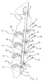
- a base panel of a gas hob is shown and is indicated generally by the reference numeral 1.
- Gas is supplied by means of a gas rail 2 to gas taps 3 to 6, which are connectable to the gas burners of the hob (not shown).
- the gas rail 2 is held against side-wall 7 of the base panel 1 by means of supports 8 to 11, which are formed from the side-wall.
- Each of the supports 8 to 11 comprises a pair of U-shaped flaps, which are cut out of side-wall 7, and which are pushed inwards, towards the gas rail 2. It is preferable that the flaps are substantially at right angles to the side-wall 7.
- the supports 8 to 11 locate the gas rail 2 and prevent it from being displaced in a direction parallel to side-wall 7.
- the gas rail 2 has outlet holes 12 to 15 for supplying gas to taps 4 to 7 respectively.
- the rail 2 is arranged in the supports 8 to 11 such that the outlet holes face away from the side-wall 7.
- Each of the gas taps 3 to 6 has a short inlet tube, which is arranged to fit in an outlet hole.
- Gas taps 3 to 6 are fastened in their respective positions against outlet holes 12 to 15 respectively by means of screw fasteners 16 to 23, which are introduced through side-wall 7 of the base panel 1, and which extend through the side-wall into the taps.
- a pair of screws fixes each tap to the side-wall 7, one screw of each pair being introduced above the gas rail 2, the other screw below.
- the screws 16 to 23 are arranged to fit into threads cut into the gas taps 3 to 6, each pair of threads being arranged above and below the inlet of each tap.
- the end 28 of the gas rail 2 is sealed by combination of a shell 29 and a plug 30.
- the shell 29 and plug 30 may be realised by any one of the blind rivets disclosed in Patent No. GB 1538872, the contents of which are incorporated herein by reference.
- the shell 29 has been radially deformed by the plug 30 to engage the inner surface of the gas rail 2, and thus form a gas tight seal.
- the plug 30 has an outwardly-splaying sleeve 31 which engages in a shoulder 32 in the shell 29, and thereby prevents the plug becoming separated from the shell.
- a mandrel 33 which mandrel comprises plug 30 and a stem 34.
- a breaker groove 35 At the junction of plug 30 and stem 34 is a breaker groove 35, which is arranged such that the plug breaks off from the stem when the groove experiences a predetermined tensile force.
- the plug 30 also has a cylindrical cut, concentric with the stem, which defines the sleeve 31.
- the shell 29 is threaded onto the stem 34, and the whole assembly is inserted in the nose of a tool 36.
- a suitable tool is described in the specification of the aforementioned patent.
- the tool 36 is then used to insert plug 30.
- stem 34 and shell 29 in the end 28 of the rail 2 until the whole length of the shell is within the rail, as shown in Figure 4b.
- the tool 36 has been actuated, and is pulling the mandrel 33 further into the body of the tool.
- the tapered section of plug 30 encounters the inner surface of the shell 29, it deforms it and urges the shell to expand radially into engagement with the inner surface of the gas rail 2.
- the enlarged section of plug 30 encounters the inner surface of the shell 29.
- the outer surface of shell 29 is in engagement with the rail 2, and therefore resists further expansion. Consequently, the plug 30 begins to wire-draw.
- Figure 4c shows the separated stem 34 and plug 30.
- the gas rail 2 is now sealed by the shell 29 and plug 30, these components being locked together by the sleeve 31 of the plug being in engagement with the shoulder 32 of the shell.
- a suitable material for the plug 30 is carbon steel and the shell 29 may be an alloy of aluminium, although other materials may be used.
- the invention has been described as a component of a gas hob. However, the invention is equally as applicable to other gas appliances.
Landscapes
- Engineering & Computer Science (AREA)
- General Engineering & Computer Science (AREA)
- Mechanical Engineering (AREA)
- Chemical & Material Sciences (AREA)
- Combustion & Propulsion (AREA)
- Portable Nailing Machines And Staplers (AREA)
- Gear Processing (AREA)
Abstract
The end of a gas rail must be sealed to prevent gas leakage, and conventionally this is
done in one of two ways. The end of the rail may be flattened and brazed, or the end may
have a cap brazed onto it. The invention provides a gas rail 2, one end 28 of which is
sealed by a shell 29 which has been radially deformed to engage the inner surface of the
gas rail by a plug 30 which remains in the shell after it has deformed it. A simply
mechanical procedure is used to seal the rail, thereby eliminating the need for brazing.
Description
This invention relates to a gas rail.
A gas rail typically is used in a hob to supply gas to a plurality of taps within the hob. It
is necessary that the termination of the gas rail is sealed to prevent gas leakage.
Conventionally, gas rails are sealed in one of two ways. The end of the rail may be
flattened and then sealed by brazing. Alternatively, a cap can be brazed, or soldered, to
the end of the rail.
The invention provides a gas rail, characterised in that one end is sealed by a shell which
has been radially deformed to engage the inner surface of the gas rail by a plug which
remains in the shell after it has deformed it.
The invention enables the rail to be sealed by a simple mechanical procedure, which
eliminates the need for brazing or soldering.
The plug advantageously has a cylindrical cut, which defines a sleeve. When the shell is
expanded by the plug, the sleeve splays outwardly to engage the shell. This feature
prevents the plug becoming separated from the shell.
The gas rail constructed according to the invention lends itself to inclusion in a gas hob.
The invention will now be described, by way of example, with reference to the
accompanying drawings, in which:-
Like reference numerals have been given to like parts throughout each of the Figures.
Referring to Figures 1 and 2, a base panel of a gas hob is shown and is indicated generally
by the reference numeral 1. Gas is supplied by means of a gas rail 2 to gas taps 3 to 6,
which are connectable to the gas burners of the hob (not shown).
The gas rail 2 is held against side-wall 7 of the base panel 1 by means of supports 8 to 11,
which are formed from the side-wall. Each of the supports 8 to 11 comprises a pair of U-shaped
flaps, which are cut out of side-wall 7, and which are pushed inwards, towards the
gas rail 2. It is preferable that the flaps are substantially at right angles to the side-wall 7.
The supports 8 to 11 locate the gas rail 2 and prevent it from being displaced in a direction
parallel to side-wall 7.
The gas rail 2 has outlet holes 12 to 15 for supplying gas to taps 4 to 7 respectively. The
rail 2 is arranged in the supports 8 to 11 such that the outlet holes face away from the
side-wall 7. Each of the gas taps 3 to 6 has a short inlet tube, which is arranged to fit in
an outlet hole. Gas taps 3 to 6 are fastened in their respective positions against outlet
holes 12 to 15 respectively by means of screw fasteners 16 to 23, which are introduced
through side-wall 7 of the base panel 1, and which extend through the side-wall into the
taps. A pair of screws fixes each tap to the side-wall 7, one screw of each pair being
introduced above the gas rail 2, the other screw below. The screws 16 to 23 are arranged
to fit into threads cut into the gas taps 3 to 6, each pair of threads being arranged above
and below the inlet of each tap.
By fixing the gas taps 3 to 6 to the side-wall 8 of the base panel 1 in this manner, the gas
rail 2 is trapped between the taps and the side-wall. Rubber washers (not shown) are
inserted between each gas tap and rail 2, in order to provide a seal to prevent gas leakage
from the outlet holes 12 to 15.
When the taps 3 to 6 are fitted to the side-wall 7, the faces of the taps abut the faces of
the U-shaped flaps which make up the supports 8 to 11. The effect of this is that the taps
are automatically aligned, which facilitates the fitting of tap spindles 24 to 27 to other
parts of the hob, for instance heat setting selectors.
It is necessary that the end 28 of the gas rail is sealed, to prevent gas leakage, and Figure
3 shows the rail 2 when sealed.
Referring to Figure 3, the end 28 of the gas rail 2 is sealed by combination of a shell 29
and a plug 30. The shell 29 and plug 30 may be realised by any one of the blind rivets
disclosed in Patent No. GB 1538872, the contents of which are incorporated herein by
reference.
The shell 29 has been radially deformed by the plug 30 to engage the inner surface of the
gas rail 2, and thus form a gas tight seal. The plug 30 has an outwardly-splaying sleeve
31 which engages in a shoulder 32 in the shell 29, and thereby prevents the plug becoming
separated from the shell.
The procedure of positioning shell 29 and plug 30 in the end 28 of the rail 2 is shown in
Figures 4a, b and c.
Referring to Figure 4a, a mandrel 33 is shown, which mandrel comprises plug 30 and a
stem 34. At the junction of plug 30 and stem 34 is a breaker groove 35, which is arranged
such that the plug breaks off from the stem when the groove experiences a predetermined
tensile force. The plug 30 also has a cylindrical cut, concentric with the stem, which
defines the sleeve 31.
The shell 29 is threaded onto the stem 34, and the whole assembly is inserted in the nose
of a tool 36. A suitable tool is described in the specification of the aforementioned patent.
The tool 36 is then used to insert plug 30. stem 34 and shell 29 in the end 28 of the rail
2 until the whole length of the shell is within the rail, as shown in Figure 4b.
In this drawing, the tool 36 has been actuated, and is pulling the mandrel 33 further into
the body of the tool. When the tapered section of plug 30 encounters the inner surface
of the shell 29, it deforms it and urges the shell to expand radially into engagement with
the inner surface of the gas rail 2.
As the mandrel 33 is pulled further into the tool 36, the enlarged section of plug 30
encounters the inner surface of the shell 29. The outer surface of shell 29 is in
engagement with the rail 2, and therefore resists further expansion. Consequently, the
plug 30 begins to wire-draw.
Continued pulling of the mandrel 33 causes the plug 30 to abut the nosetip of the tool 36,
which splays sleeve 31 into engagement with the shell 29. Pulling beyond this point
subjects the breaker groove 35 to a greater force than experienced hitherto. As a result,
the stem 34 and plug 30 disengage from each other at the breaker groove 35.
Figure 4c shows the separated stem 34 and plug 30. The gas rail 2 is now sealed by the
shell 29 and plug 30, these components being locked together by the sleeve 31 of the plug
being in engagement with the shoulder 32 of the shell.
A suitable material for the plug 30 is carbon steel and the shell 29 may be an alloy of
aluminium, although other materials may be used.
The invention has been described as a component of a gas hob. However, the invention
is equally as applicable to other gas appliances.
Further variations may be made without departing from the scope of the invention, and
these will be apparent to those skilled in the art.
Claims (4)
- A gas rail, characterised in that one end is sealed by a shell (29) which has been radially deformed to engage the inner surface of the gas rail (2) by a plug (30) which remains in the shell after it has deformed it.
- A gas rail as claimed in claim 1, in which the plug (30) has a cylindrical cut to define a sleeve (31) which splays outwardly to engage the shell (29) when the shell is expanded by the plug.
- A gas hob including a gas rail as claimed in claim 1 or 2.
- A gas appliance including a gas rail as claimed in claim 1 or 2.
Applications Claiming Priority (2)
| Application Number | Priority Date | Filing Date | Title |
|---|---|---|---|
| GB9709391 | 1997-05-09 | ||
| GB9709391A GB2325039A (en) | 1997-05-09 | 1997-05-09 | Gas rail with plugged end |
Publications (1)
| Publication Number | Publication Date |
|---|---|
| EP0877193A1 true EP0877193A1 (en) | 1998-11-11 |
Family
ID=10812021
Family Applications (1)
| Application Number | Title | Priority Date | Filing Date |
|---|---|---|---|
| EP98303664A Withdrawn EP0877193A1 (en) | 1997-05-09 | 1998-05-11 | A gas rail |
Country Status (2)
| Country | Link |
|---|---|
| EP (1) | EP0877193A1 (en) |
| GB (1) | GB2325039A (en) |
Cited By (8)
| Publication number | Priority date | Publication date | Assignee | Title |
|---|---|---|---|---|
| WO2000037844A1 (en) * | 1998-12-22 | 2000-06-29 | Umformtechnik Und Kraftfahrzeugkomponenten Meissen Gmbh | Device for the tight sealing of thin-walled hollow spaces subjected to a pressure medium |
| WO2001086190A1 (en) * | 2000-05-11 | 2001-11-15 | Textron Fastening Systems Limited | Closed end sealing plug |
| EP2199682A1 (en) * | 2008-12-16 | 2010-06-23 | BSH Bosch und Siemens Hausgeräte GmbH | Household device with a gas conduit |
| EP1944545A3 (en) * | 2007-01-05 | 2012-12-26 | Coprecitec, S.L. | Gas manifold for a cooking range with an emergency tap |
| CN103143579A (en) * | 2013-02-25 | 2013-06-12 | 燕山大学 | High pressure liquid lubrication drawing tail end sealing method |
| CN117212453A (en) * | 2023-08-07 | 2023-12-12 | 苏州誉高紧固系统有限公司 | A pore plugging device and a pore plugging method |
| EP4345357A1 (en) * | 2022-09-28 | 2024-04-03 | Sfc Koenig Ag | Closure device for tight sealing a hole |
| CN119825924A (en) * | 2025-03-18 | 2025-04-15 | 苏州誉高紧固系统有限公司 | Pore canal plugging device, pore canal plugging system, device with sealed hole and pore canal plugging method |
Citations (4)
| Publication number | Priority date | Publication date | Assignee | Title |
|---|---|---|---|---|
| GB1538872A (en) * | 1975-04-01 | 1979-01-24 | Avdel Ltd | Blind rivet |
| GB2094928A (en) * | 1981-02-13 | 1982-09-22 | Avdel Ltd | Plug assembly and method of plugging a passage |
| US4646816A (en) * | 1985-09-06 | 1987-03-03 | Samuel Rothstein | Simplified tube plugging |
| GB2252382A (en) * | 1991-01-29 | 1992-08-05 | British Gas Plc | Blocking pipes |
Family Cites Families (3)
| Publication number | Priority date | Publication date | Assignee | Title |
|---|---|---|---|---|
| GB852216A (en) * | 1957-06-19 | 1960-10-26 | Exxon Research Engineering Co | Tube plugging device |
| US3525365A (en) * | 1966-10-17 | 1970-08-25 | Pneumo Dynamics Corp | Expansion plug |
| CH503923A (en) * | 1968-11-01 | 1971-02-28 | Koenig Ag Dr Ing | Method and device for closing bores |
-
1997
- 1997-05-09 GB GB9709391A patent/GB2325039A/en not_active Withdrawn
-
1998
- 1998-05-11 EP EP98303664A patent/EP0877193A1/en not_active Withdrawn
Patent Citations (4)
| Publication number | Priority date | Publication date | Assignee | Title |
|---|---|---|---|---|
| GB1538872A (en) * | 1975-04-01 | 1979-01-24 | Avdel Ltd | Blind rivet |
| GB2094928A (en) * | 1981-02-13 | 1982-09-22 | Avdel Ltd | Plug assembly and method of plugging a passage |
| US4646816A (en) * | 1985-09-06 | 1987-03-03 | Samuel Rothstein | Simplified tube plugging |
| GB2252382A (en) * | 1991-01-29 | 1992-08-05 | British Gas Plc | Blocking pipes |
Cited By (11)
| Publication number | Priority date | Publication date | Assignee | Title |
|---|---|---|---|---|
| WO2000037844A1 (en) * | 1998-12-22 | 2000-06-29 | Umformtechnik Und Kraftfahrzeugkomponenten Meissen Gmbh | Device for the tight sealing of thin-walled hollow spaces subjected to a pressure medium |
| WO2001086190A1 (en) * | 2000-05-11 | 2001-11-15 | Textron Fastening Systems Limited | Closed end sealing plug |
| US6966342B2 (en) * | 2000-05-11 | 2005-11-22 | Textron Fastening Systems Limited | Closed end sealing plug |
| EP1944545A3 (en) * | 2007-01-05 | 2012-12-26 | Coprecitec, S.L. | Gas manifold for a cooking range with an emergency tap |
| EP2199682A1 (en) * | 2008-12-16 | 2010-06-23 | BSH Bosch und Siemens Hausgeräte GmbH | Household device with a gas conduit |
| CN103143579A (en) * | 2013-02-25 | 2013-06-12 | 燕山大学 | High pressure liquid lubrication drawing tail end sealing method |
| CN103143579B (en) * | 2013-02-25 | 2015-04-08 | 燕山大学 | High pressure liquid lubrication drawing tail end sealing method |
| EP4345357A1 (en) * | 2022-09-28 | 2024-04-03 | Sfc Koenig Ag | Closure device for tight sealing a hole |
| CN117212453A (en) * | 2023-08-07 | 2023-12-12 | 苏州誉高紧固系统有限公司 | A pore plugging device and a pore plugging method |
| CN119825924A (en) * | 2025-03-18 | 2025-04-15 | 苏州誉高紧固系统有限公司 | Pore canal plugging device, pore canal plugging system, device with sealed hole and pore canal plugging method |
| CN119825924B (en) * | 2025-03-18 | 2025-07-04 | 苏州誉高紧固系统有限公司 | Pore canal plugging device, pore canal plugging system, device with sealed hole and pore canal plugging method |
Also Published As
| Publication number | Publication date |
|---|---|
| GB9709391D0 (en) | 1997-07-02 |
| GB2325039A (en) | 1998-11-11 |
Similar Documents
| Publication | Publication Date | Title |
|---|---|---|
| US7093862B2 (en) | Tube joint and apparatus for producing the same | |
| EP0766804B1 (en) | Member and tube assembly and method | |
| US3047181A (en) | Rivet combination | |
| JP4088923B2 (en) | Pipe fittings for corrugated flexible pipes | |
| US3847421A (en) | Quick connect tube coupling joint | |
| US4580936A (en) | Blind rivet assembly | |
| EP0699284B1 (en) | Joining thermoplastic pipe to a coupling | |
| US3822074A (en) | Releasable coupling for tubular members and method for assemblying said coupling | |
| US6009610A (en) | Re-enterable conduit sealing assembly and method | |
| US20090108580A1 (en) | Plug-in coupling for fluidic systems | |
| EP0877193A1 (en) | A gas rail | |
| US2832254A (en) | Nut and expanding sleeve retainer therefor | |
| EP0877206A2 (en) | A gas hob | |
| EP0556993A1 (en) | Blind pin fixing | |
| GB2163823A (en) | Self-plugging blind rivet | |
| EP0339156A2 (en) | Pipe fitting | |
| GB1595283A (en) | Bolts and the like fastening devices | |
| EP0957305A2 (en) | A pneumatic connector | |
| GB2094928A (en) | Plug assembly and method of plugging a passage | |
| US20100176585A1 (en) | Method for attaching tube and fittings | |
| US3891251A (en) | Swaged-tube coupling | |
| EP3255345A1 (en) | Installation tool and system for assembling a gas turbine combustor | |
| ZA852571B (en) | Pipe repair sleeve apparatus and method of repairing a damaged pipe | |
| US3455581A (en) | Means to connect threaded and non-threaded surfaces | |
| EP4630732A1 (en) | Holding device, method for fixing a functional element, and cooking device comprising same |
Legal Events
| Date | Code | Title | Description |
|---|---|---|---|
| PUAI | Public reference made under article 153(3) epc to a published international application that has entered the european phase |
Free format text: ORIGINAL CODE: 0009012 |
|
| AK | Designated contracting states |
Kind code of ref document: A1 Designated state(s): AT BE CH CY DE DK ES FI FR GB GR IE IT LI LU MC NL PT SE |
|
| AX | Request for extension of the european patent |
Free format text: AL;LT;LV;MK;RO;SI |
|
| AKX | Designation fees paid | ||
| STAA | Information on the status of an ep patent application or granted ep patent |
Free format text: STATUS: THE APPLICATION IS DEEMED TO BE WITHDRAWN |
|
| 18D | Application deemed to be withdrawn |
Effective date: 19990512 |