EP2199663A1 - Blende einer Kraftfahrzeug-Scheinwerfereinheit mit Protuberanz für die Verlängerung einer Scheinwerferwand - Google Patents
Blende einer Kraftfahrzeug-Scheinwerfereinheit mit Protuberanz für die Verlängerung einer Scheinwerferwand Download PDFInfo
- Publication number
- EP2199663A1 EP2199663A1 EP09173247A EP09173247A EP2199663A1 EP 2199663 A1 EP2199663 A1 EP 2199663A1 EP 09173247 A EP09173247 A EP 09173247A EP 09173247 A EP09173247 A EP 09173247A EP 2199663 A1 EP2199663 A1 EP 2199663A1
- Authority
- EP
- European Patent Office
- Prior art keywords
- mask
- reflector
- wall
- fixing means
- tabs
- Prior art date
- Legal status (The legal status is an assumption and is not a legal conclusion. Google has not performed a legal analysis and makes no representation as to the accuracy of the status listed.)
- Withdrawn
Links
Images


Classifications
-
- F—MECHANICAL ENGINEERING; LIGHTING; HEATING; WEAPONS; BLASTING
- F21—LIGHTING
- F21S—NON-PORTABLE LIGHTING DEVICES; SYSTEMS THEREOF; VEHICLE LIGHTING DEVICES SPECIALLY ADAPTED FOR VEHICLE EXTERIORS
- F21S43/00—Signalling devices specially adapted for vehicle exteriors, e.g. brake lamps, direction indicator lights or reversing lights
- F21S43/50—Signalling devices specially adapted for vehicle exteriors, e.g. brake lamps, direction indicator lights or reversing lights characterised by aesthetic components not otherwise provided for, e.g. decorative trim, partition walls or covers
- F21S43/51—Attachment thereof
-
- F—MECHANICAL ENGINEERING; LIGHTING; HEATING; WEAPONS; BLASTING
- F21—LIGHTING
- F21S—NON-PORTABLE LIGHTING DEVICES; SYSTEMS THEREOF; VEHICLE LIGHTING DEVICES SPECIALLY ADAPTED FOR VEHICLE EXTERIORS
- F21S41/00—Illuminating devices specially adapted for vehicle exteriors, e.g. headlamps
- F21S41/30—Illuminating devices specially adapted for vehicle exteriors, e.g. headlamps characterised by reflectors
- F21S41/32—Optical layout thereof
- F21S41/36—Combinations of two or more separate reflectors
-
- F—MECHANICAL ENGINEERING; LIGHTING; HEATING; WEAPONS; BLASTING
- F21—LIGHTING
- F21S—NON-PORTABLE LIGHTING DEVICES; SYSTEMS THEREOF; VEHICLE LIGHTING DEVICES SPECIALLY ADAPTED FOR VEHICLE EXTERIORS
- F21S41/00—Illuminating devices specially adapted for vehicle exteriors, e.g. headlamps
- F21S41/40—Illuminating devices specially adapted for vehicle exteriors, e.g. headlamps characterised by screens, non-reflecting members, light-shielding members or fixed shades
- F21S41/47—Attachment thereof
-
- F—MECHANICAL ENGINEERING; LIGHTING; HEATING; WEAPONS; BLASTING
- F21—LIGHTING
- F21S—NON-PORTABLE LIGHTING DEVICES; SYSTEMS THEREOF; VEHICLE LIGHTING DEVICES SPECIALLY ADAPTED FOR VEHICLE EXTERIORS
- F21S43/00—Signalling devices specially adapted for vehicle exteriors, e.g. brake lamps, direction indicator lights or reversing lights
- F21S43/20—Signalling devices specially adapted for vehicle exteriors, e.g. brake lamps, direction indicator lights or reversing lights characterised by refractors, transparent cover plates, light guides or filters
- F21S43/255—Filters
-
- F—MECHANICAL ENGINEERING; LIGHTING; HEATING; WEAPONS; BLASTING
- F21—LIGHTING
- F21S—NON-PORTABLE LIGHTING DEVICES; SYSTEMS THEREOF; VEHICLE LIGHTING DEVICES SPECIALLY ADAPTED FOR VEHICLE EXTERIORS
- F21S43/00—Signalling devices specially adapted for vehicle exteriors, e.g. brake lamps, direction indicator lights or reversing lights
- F21S43/40—Signalling devices specially adapted for vehicle exteriors, e.g. brake lamps, direction indicator lights or reversing lights characterised by the combination of reflectors and refractors
-
- F—MECHANICAL ENGINEERING; LIGHTING; HEATING; WEAPONS; BLASTING
- F21—LIGHTING
- F21S—NON-PORTABLE LIGHTING DEVICES; SYSTEMS THEREOF; VEHICLE LIGHTING DEVICES SPECIALLY ADAPTED FOR VEHICLE EXTERIORS
- F21S43/00—Signalling devices specially adapted for vehicle exteriors, e.g. brake lamps, direction indicator lights or reversing lights
- F21S43/50—Signalling devices specially adapted for vehicle exteriors, e.g. brake lamps, direction indicator lights or reversing lights characterised by aesthetic components not otherwise provided for, e.g. decorative trim, partition walls or covers
-
- F—MECHANICAL ENGINEERING; LIGHTING; HEATING; WEAPONS; BLASTING
- F21—LIGHTING
- F21V—FUNCTIONAL FEATURES OR DETAILS OF LIGHTING DEVICES OR SYSTEMS THEREOF; STRUCTURAL COMBINATIONS OF LIGHTING DEVICES WITH OTHER ARTICLES, NOT OTHERWISE PROVIDED FOR
- F21V17/00—Fastening of component parts of lighting devices, e.g. shades, globes, refractors, reflectors, filters, screens, grids or protective cages
- F21V17/10—Fastening of component parts of lighting devices, e.g. shades, globes, refractors, reflectors, filters, screens, grids or protective cages characterised by specific fastening means or way of fastening
- F21V17/16—Fastening of component parts of lighting devices, e.g. shades, globes, refractors, reflectors, filters, screens, grids or protective cages characterised by specific fastening means or way of fastening by deformation of parts; Snap action mounting
- F21V17/164—Fastening of component parts of lighting devices, e.g. shades, globes, refractors, reflectors, filters, screens, grids or protective cages characterised by specific fastening means or way of fastening by deformation of parts; Snap action mounting the parts being subjected to bending, e.g. snap joints
Definitions
- the invention relates to motor vehicle light units, and more specifically the masks that comprise some of these optical blocks.
- certain motor vehicle optical units comprise a mask, a reflector, a housing to which the mask and the reflector are joined, and an ice placed in front of the reflector as well as possibly in front of the mask and secured to the housing and / or the reflector and / or the mask.
- the reflector is a part that provides a photometric function, such as for example to reflect forwards the light that is emitted by an internal lamp.
- the mask is a piece that defines a part of the style of the optical block. It is usually metallized and placed behind the ice so that at least its front part is visible from the outside.
- the reflector and the mask are two pieces that are generally close to each other.
- the reflector is generally located in the housing slightly set back from the mask with respect to the ice. As a result, a slight day may exist between the front end of the wall defining the reflector and the peripheral edge of the mask. Therefore, when the reflector is illuminated by its lamp, some of the light it reflects can pass through the light day existing and lead to the back of the mask, which can be unsightly, or even misleading. Similarly, when the rear face of the mask is illuminated by a light source, a portion of this light can pass through the existing light day and lead into the reflector, which is seen at the ice and is unsightly, or even misleading.
- the object of the invention is in particular to remedy this drawback.
- a mask intended to be part of a motor vehicle optical unit comprising at least one defined reflector by at least one wall providing at least partially a photometric function, and comprising a peripheral edge comprising in at least one location, intended to be substantially in contact with a selected zone of this wall, an outgrowth intended to extend forward the wall at its chosen area.
- the invention also proposes an optical block, intended to be implanted in a motor vehicle, and comprising a mask of the type of the one presented above, a reflector defined by at least one wall ensuring at least partially a photometric function, the mask and the reflector being located next to each other a housing which is secured to the mask and the reflector, and an ice, placed at least in front of the reflector and secured to the housing and / or the mask and / or the reflector.
- the mask is preferably located below the reflector.
- the mask can be located alternately above the reflector.
- the arrangement of the mask beside the reflector is understood as opposed to a disposition one behind the other.
- the mask is arranged next to the reflector so that most of the light from the reflector and intended to cross the ice does not cross or does not arrive on the mask. Also, the mask is disposed beside the reflector so that most of the light from the mask or through the mask and intended to pass through the ice does not arrive on the reflector.
- the mask preferably comprises several holes. These holes mimic or simulate advantageously light emitting diodes. Instead of the holes may be used disjoint areas at least partially transparent between them distributed on an opaque mask background. In place of the holes can be used disjoint areas between them transparent distributed on a background of translucent mask.
- the reflector may for example comprise a rear face provided, at a selected zone of its wall, with second fixing means adapted to cooperate with first fixing means defined on a front face of the mask, at a location, so as to allow the assembly of the mask to the reflector.
- the object of the invention is notably to propose a mask (M) for an optical block (BO) intended to be implanted in a motor vehicle.
- the optical unit is a headlight (or front projector) intended to be installed in the front of a motor vehicle.
- the invention is not limited to this type of implantation. It also relates to certain optical blocks, such as signal rear lamps, intended to be installed in the rear of a motor vehicle.
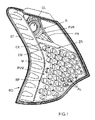
- Such an optical block BO comprises at least one reflector R, a mask M, and a housing BT as well as generally an ice (not shown).
- the mask M and the reflector R are secured to the housing BT.
- the ice is placed at least in front of the reflector R and possibly in front of the mask M and is secured to the LV housing and / or the reflector R and / or the mask M.
- the reflector R is defined by at least one wall PR which at least partially provides a photometric function.
- the wall PR comprises for example a central opening OL for the passage of a transmitting part of a lamp (or bulb).
- the wall PR is shaped and processed (eg metallized) so as to reflect forwards, in a selected solid angle, the light that is emitted by the lamp.
- This predetermined reflection function (and therefore the shaping of the light) constitutes the photometric function of the reflector R.
- the reflector R comprises a front face FVR which is oriented towards the mirror and is responsible for reflecting the light forward and a rear face FRR opposite to its front face FVR.
- the mask M comprises a front face FVM which is oriented outwards (and possibly towards the glass) and a rear face FRM opposite to its front face FVM.
- the mask M comprises a peripheral edge BP which comprises at least one location EM intended to be substantially in contact with a selected zone ZR of the wall PR of the reflector R. As illustrated in FIGS. figures 1 , 3 and 6 this selected zone ZR is for example located at the front end of the wall PR of the reflector R, opposite its central opening OL.
- the optical block BO may comprise several (at least two) reflectors R each comprising a wall PR having a selected zone ZR intended to be substantially in contact with a location EM of the peripheral edge BP of the mask M. It will then be understood that the mask M comprises in this case several different EM locations respectively associated with the different reflectors R.
- peripheral edge BP has at each location EM a conformation which is substantially identical to that of the selected zone ZR of the corresponding wall PR, so as to prevent there being a day between said reflector R and the mask M. This makes it possible to prevent the light from passing from one to the other upstream of the rear face FRM of the mask M.
- the mask M may for example provide a style function. This is particularly the case in the nonlimiting exemplary embodiment illustrated on the Figures 1 to 4 and 6 . Indeed, it comprises here cells (or holes) AL for imitating light emitting diodes (or LEDs).
- the rear face FRM of the mask M is placed in front of a light source, consisting for example of at least one lamp or a bulb.
- each cell AL may be optionally arranged in the form of a prism designed to focus forward the light it receives from the source.
- the mask M also performs a photometric function thanks to its prismatic cells OL.
- the peripheral edge BP of the mask M comprises at each location EM an outgrowth (or protrusion or projection) EX intended to extend forward the wall PR at its chosen zone ZR.
- the protrusion EX prevents that parasitic light coming from the reflector R does not enter the mask M via its front face FVM.
- the protrusion EX thus also acts as a kind of wall ensuring the light tightness between the reflector R and the mask M front side (that is to say upstream of the ice). Thanks to this wall, the light rays coming from the reflector R and the mask M are no longer likely to cross each other and the functions they help to ensure can be well differentiated.
- the protrusion EX it is particularly advantageous for the protrusion EX to be arranged (or shaped) so as to participate in the photometric function of the reflector R.
- its forward extension and its profile are predetermined and it presents on its face which is substantially oriented towards the reflector R an aspect which is similar (or identical) to that which presents the front face FVR of the wall PR of the reflector R at least at its chosen zone ZR.
- this face may comprise a metallization and / or ridges and / or a molding grain identical to those of the front face FVR of the wall PR (at least locally).
- the protrusion EX is preferably an integral part of the mask M.
- the mask M according to the invention can thus be made in one piece by molding, for example. But, it could be envisaged that the protrusion EX is an insert on the mask M, possibly by gluing or co-molding or over-molding.
- first fixing means MF1 on the rear face FRM of the mask M at the location EM
- second fixing means MF2 on the rear face FRR of the zone chosen ZR from the PR wall are arranged to cooperate together to assemble the mask M and the reflector R.
- the first fixing means MF1 may for example be arranged in the form of at least two first tabs projecting rearwardly from the rear face FRM of the mask M, at the location EM, in a direction which is opposed to that of the protrusion EX, and the second attachment means MF2 may for example be arranged in the form of at least two second tabs which are adapted to cooperate with the first tabs MF1.
- the first legs MF1 may be lugs (or teeth) which are substantially I-shaped (capital i, that is to say, substantially rectangular parallelepiped shape).
- the second legs MF2 may be substantially L-shaped so as to house respectively the first legs MF1. The smallest part of the L then runs from the rear face FRR of the selected zone ZR of the wall PR, and has an extension which is substantially equal, by a larger value, to the thickness of the corresponding first lug MF1.
- the first legs MF1 are preferably offset towards the center of the mask M, with respect to the end of the peripheral edge BP, by a distance which is substantially equal to the thickness of the wall PR of the reflector R at its zone chosen ZR, so that there is a surface continuity between the wall PR and the protrusion EX.
- first legs MF1 are housed (fit) tightly in the housing defined by the corresponding second leg MF2, so as to allow the assembly of the mask M and the reflector R for effective light sealing.
- fastening means may be envisaged, and in particular clipping or latching means.
- the mask M may for example be made of a rigid synthetic material, such as a polyphase copolymer (for example Acrylonitrile Butadiene Styrene (or ABS)). It may be optionally colored.
- a polyphase copolymer for example Acrylonitrile Butadiene Styrene (or ABS)
- ABS Acrylonitrile Butadiene Styrene
Landscapes
- Engineering & Computer Science (AREA)
- General Engineering & Computer Science (AREA)
- Non-Portable Lighting Devices Or Systems Thereof (AREA)
- Investigating Or Analysing Materials By Optical Means (AREA)
- Optical Elements Other Than Lenses (AREA)
Applications Claiming Priority (1)
| Application Number | Priority Date | Filing Date | Title |
|---|---|---|---|
| FR0858762A FR2940204B1 (fr) | 2008-12-18 | 2008-12-18 | Masque de bloc optique de vehicule automobile a excroissance pour la prolongation d'une paroi de reflecteur |
Publications (1)
| Publication Number | Publication Date |
|---|---|
| EP2199663A1 true EP2199663A1 (de) | 2010-06-23 |
Family
ID=40848580
Family Applications (1)
| Application Number | Title | Priority Date | Filing Date |
|---|---|---|---|
| EP09173247A Withdrawn EP2199663A1 (de) | 2008-12-18 | 2009-10-16 | Blende einer Kraftfahrzeug-Scheinwerfereinheit mit Protuberanz für die Verlängerung einer Scheinwerferwand |
Country Status (2)
| Country | Link |
|---|---|
| EP (1) | EP2199663A1 (de) |
| FR (1) | FR2940204B1 (de) |
Cited By (6)
| Publication number | Priority date | Publication date | Assignee | Title |
|---|---|---|---|---|
| EP3354972A1 (de) * | 2017-01-27 | 2018-08-01 | PSA Automobiles SA | Beleuchtungsvorrichtung mit maske mit diamantspitzen-motiven |
| FR3081537A1 (fr) * | 2018-05-28 | 2019-11-29 | Psa Automobiles Sa | Bloc optique de vehicule automobile et vehicule automobile comportant un tel element. |
| FR3088596A1 (fr) * | 2018-11-16 | 2020-05-22 | Psa Automobiles Sa | Bloc optique pour vehicule automobile pourvu d’un masque fixe sur une armature |
| FR3088869A1 (fr) * | 2018-11-26 | 2020-05-29 | Psa Automobiles Sa | Dispositif de pré-positionnement et de maintien d’un élément sur un boitier |
| FR3089466A1 (fr) * | 2018-12-07 | 2020-06-12 | Psa Automobiles Sa | Dispositif de pré-positionnement et de maintien sous contrainte d’un élément sur un boitier. |
| WO2022228853A1 (de) * | 2021-04-28 | 2022-11-03 | Bayerische Motoren Werke Aktiengesellschaft | Scheinwerfer für ein kraftfahrzeug |
Citations (6)
| Publication number | Priority date | Publication date | Assignee | Title |
|---|---|---|---|---|
| DE3336178A1 (de) * | 1983-10-05 | 1985-04-25 | Robert Bosch Gmbh, 7000 Stuttgart | Signalleuchte, insbesondere vordere blinkleuchte, fuer kraftfahrzeuge |
| US5560706A (en) * | 1992-12-04 | 1996-10-01 | Koito Manufacturing Co., Ltd. | Seal structure and process for a vehicular lamp |
| US5562338A (en) * | 1993-12-15 | 1996-10-08 | Koito Manufacturing Co., Ltd. | Dual lens lamp assembly for vehicular use |
| DE10355210A1 (de) * | 2003-11-26 | 2005-06-23 | Hella Kgaa Hueck & Co. | Leuchteinheit für Fahrzeuge |
| EP1672275A1 (de) * | 2004-12-17 | 2006-06-21 | Valeo Vision | Beleuchtungs-oder Signal-Vorrichtung für Kraftfahrzeug |
| EP1762777A2 (de) * | 2005-09-08 | 2007-03-14 | Hella KG Hueck & Co. | Leuchteinheit für Kraftfahrzeuge |
-
2008
- 2008-12-18 FR FR0858762A patent/FR2940204B1/fr active Active
-
2009
- 2009-10-16 EP EP09173247A patent/EP2199663A1/de not_active Withdrawn
Patent Citations (6)
| Publication number | Priority date | Publication date | Assignee | Title |
|---|---|---|---|---|
| DE3336178A1 (de) * | 1983-10-05 | 1985-04-25 | Robert Bosch Gmbh, 7000 Stuttgart | Signalleuchte, insbesondere vordere blinkleuchte, fuer kraftfahrzeuge |
| US5560706A (en) * | 1992-12-04 | 1996-10-01 | Koito Manufacturing Co., Ltd. | Seal structure and process for a vehicular lamp |
| US5562338A (en) * | 1993-12-15 | 1996-10-08 | Koito Manufacturing Co., Ltd. | Dual lens lamp assembly for vehicular use |
| DE10355210A1 (de) * | 2003-11-26 | 2005-06-23 | Hella Kgaa Hueck & Co. | Leuchteinheit für Fahrzeuge |
| EP1672275A1 (de) * | 2004-12-17 | 2006-06-21 | Valeo Vision | Beleuchtungs-oder Signal-Vorrichtung für Kraftfahrzeug |
| EP1762777A2 (de) * | 2005-09-08 | 2007-03-14 | Hella KG Hueck & Co. | Leuchteinheit für Kraftfahrzeuge |
Cited By (9)
| Publication number | Priority date | Publication date | Assignee | Title |
|---|---|---|---|---|
| EP3354972A1 (de) * | 2017-01-27 | 2018-08-01 | PSA Automobiles SA | Beleuchtungsvorrichtung mit maske mit diamantspitzen-motiven |
| FR3062451A1 (fr) * | 2017-01-27 | 2018-08-03 | Peugeot Citroen Automobiles Sa | Dispositif d’eclairage a masque a motifs en pointe de diamant |
| FR3081537A1 (fr) * | 2018-05-28 | 2019-11-29 | Psa Automobiles Sa | Bloc optique de vehicule automobile et vehicule automobile comportant un tel element. |
| WO2019229314A1 (fr) * | 2018-05-28 | 2019-12-05 | Psa Automobiles Sa | Bloc optique de vehicule automobile et vehicule automobile comportant un tel element |
| FR3088596A1 (fr) * | 2018-11-16 | 2020-05-22 | Psa Automobiles Sa | Bloc optique pour vehicule automobile pourvu d’un masque fixe sur une armature |
| WO2020099746A1 (fr) * | 2018-11-16 | 2020-05-22 | Psa Automobiles Sa | Bloc optique pour véhicule automobile pourvu d'un masque fixé sur une armature |
| FR3088869A1 (fr) * | 2018-11-26 | 2020-05-29 | Psa Automobiles Sa | Dispositif de pré-positionnement et de maintien d’un élément sur un boitier |
| FR3089466A1 (fr) * | 2018-12-07 | 2020-06-12 | Psa Automobiles Sa | Dispositif de pré-positionnement et de maintien sous contrainte d’un élément sur un boitier. |
| WO2022228853A1 (de) * | 2021-04-28 | 2022-11-03 | Bayerische Motoren Werke Aktiengesellschaft | Scheinwerfer für ein kraftfahrzeug |
Also Published As
| Publication number | Publication date |
|---|---|
| FR2940204A1 (fr) | 2010-06-25 |
| FR2940204B1 (fr) | 2011-10-14 |
Similar Documents
| Publication | Publication Date | Title |
|---|---|---|
| EP2199663A1 (de) | Blende einer Kraftfahrzeug-Scheinwerfereinheit mit Protuberanz für die Verlängerung einer Scheinwerferwand | |
| EP2598374B1 (de) | Signalleuchte für kraftfahrzeug | |
| EP2504619A1 (de) | Beleuchtungseinheit mit zwischen einem reflektor und einem schirm eingesetzten lichtleiter(n) | |
| WO2012038629A1 (fr) | Dispositif lumineux à guides de lumière, pour un bloc optique de véhicule, et masque et boîtier associés | |
| WO2017121944A1 (fr) | Bloc optique comprenant un feu de signalisation doté d'un guide de lumière plat saillant de sa glace extérieure | |
| EP2598795A1 (de) | Vorrichtung zur befestigung eines ersten elemetns an einem zweiten element mittels einrastung zwischen und arretiernasen und befestigungsnasen | |
| FR2904999A1 (fr) | Projecteur de vehicule | |
| FR2941282A1 (fr) | Masque a cache de lumiere pour un bloc optique de vehicule automobile | |
| EP2080948A2 (de) | Element der rückwärtigen Scheinwerfereinheit eines Kraftfahrzeugs, das einen Rückstrahler mit Diffusionslinsen und Hintergrundbeleuchtung bildet | |
| EP2379941B1 (de) | Kraftfahrzeugleuchteneinheit mit funktionaler trennplatte, die durch festes anpressen an ihrer hauptwand unter elastischer belastung daran befestigt ist | |
| EP4065884B1 (de) | Beleuchtungsvorrichtung für ein kraftfahrzeug | |
| FR3082153A1 (fr) | Bloc optique pour vehicule automobile pourvu d’un masque chausse sur au moins un reflecteur | |
| EP2169297B1 (de) | Optisches Modul, das ein optisches Ablenkelement umfasst | |
| EP3883816B1 (de) | Optische fahrzeugeinheit mit in bezug auf eine maske schwebenden retroreflektoren | |
| EP2952804B1 (de) | Leuchtmodul für fahrzeug und befestigungsverfahren | |
| FR3018587A1 (fr) | Module lumineux comprenant des sources lumineuses surfaciques | |
| FR2953277A1 (fr) | Masque de bloc optique de vehicule, a paroi partiellement deplacable | |
| EP2093483B1 (de) | LED-imitierende Kfz-Beleuchtungseinheit mit einer Blende | |
| FR2952162A1 (fr) | Bloc optique de vehicule automobile, a masque et ecran(s) constituant un element monobloc | |
| FR3018750A1 (fr) | Boitier de projecteur ou de feu de vehicule automobile obtenu par moulage | |
| FR2977001A1 (fr) | Dispositif d'occultation a fonction(s) d'eclairage, pour un bloc optique de vehicule | |
| FR2761648A1 (fr) | Dispositif d'eclairage ou de signalisation a glace affleurante et moyens de calage, pour vehicule automobile | |
| EP2143993A1 (de) | Scheinwerfereinheit eines Kraftfahrzeugs mit optimierter Befestigung der Abschirmung am Gehäuse und Verfahren zur Befestigung der Abschirmung am Gehäuse | |
| FR2972165A1 (fr) | Dispositif d'aide aux interventions a l'interieur d'une partie arriere d'un bloc optique de vehicule | |
| FR2935115A1 (fr) | Masque de bloc optique de vehicule automobile a insert(s) interchangeable(s) |
Legal Events
| Date | Code | Title | Description |
|---|---|---|---|
| PUAI | Public reference made under article 153(3) epc to a published international application that has entered the european phase |
Free format text: ORIGINAL CODE: 0009012 |
|
| AK | Designated contracting states |
Kind code of ref document: A1 Designated state(s): AT BE BG CH CY CZ DE DK EE ES FI FR GB GR HR HU IE IS IT LI LT LU LV MC MK MT NL NO PL PT RO SE SI SK SM TR |
|
| AX | Request for extension of the european patent |
Extension state: AL BA RS |
|
| 17P | Request for examination filed |
Effective date: 20101210 |
|
| 17Q | First examination report despatched |
Effective date: 20110121 |
|
| STAA | Information on the status of an ep patent application or granted ep patent |
Free format text: STATUS: THE APPLICATION IS DEEMED TO BE WITHDRAWN |
|
| 18D | Application deemed to be withdrawn |
Effective date: 20130503 |