EP2199467B1 - Poutre égaliseuse et procédé destiné à la fabrication d'un revêtement de chaussée - Google Patents
Poutre égaliseuse et procédé destiné à la fabrication d'un revêtement de chaussée Download PDFInfo
- Publication number
- EP2199467B1 EP2199467B1 EP08021844A EP08021844A EP2199467B1 EP 2199467 B1 EP2199467 B1 EP 2199467B1 EP 08021844 A EP08021844 A EP 08021844A EP 08021844 A EP08021844 A EP 08021844A EP 2199467 B1 EP2199467 B1 EP 2199467B1
- Authority
- EP
- European Patent Office
- Prior art keywords
- screed
- extension
- frame
- base
- paving
- Prior art date
- Legal status (The legal status is an assumption and is not a legal conclusion. Google has not performed a legal analysis and makes no representation as to the accuracy of the status listed.)
- Active
Links
- 238000000034 method Methods 0.000 title claims description 10
- 238000004519 manufacturing process Methods 0.000 title description 2
- 230000007704 transition Effects 0.000 claims description 21
- SEQDDYPDSLOBDC-UHFFFAOYSA-N Temazepam Chemical compound N=1C(O)C(=O)N(C)C2=CC=C(Cl)C=C2C=1C1=CC=CC=C1 SEQDDYPDSLOBDC-UHFFFAOYSA-N 0.000 claims description 7
- 239000000725 suspension Substances 0.000 claims description 6
- 230000005540 biological transmission Effects 0.000 claims description 5
- 230000001360 synchronised effect Effects 0.000 claims description 4
- 230000000712 assembly Effects 0.000 claims 21
- 238000000429 assembly Methods 0.000 claims 21
- 238000009434 installation Methods 0.000 description 16
- 238000006073 displacement reaction Methods 0.000 description 15
- 238000009499 grossing Methods 0.000 description 13
- 230000008859 change Effects 0.000 description 12
- 230000000875 corresponding effect Effects 0.000 description 8
- 239000000463 material Substances 0.000 description 6
- 238000007667 floating Methods 0.000 description 4
- 238000006243 chemical reaction Methods 0.000 description 2
- 238000010276 construction Methods 0.000 description 2
- 230000002596 correlated effect Effects 0.000 description 2
- 239000004606 Fillers/Extenders Substances 0.000 description 1
- 230000009471 action Effects 0.000 description 1
- 230000008901 benefit Effects 0.000 description 1
- 230000000903 blocking effect Effects 0.000 description 1
- 239000004566 building material Substances 0.000 description 1
- 230000001276 controlling effect Effects 0.000 description 1
- 230000008878 coupling Effects 0.000 description 1
- 238000010168 coupling process Methods 0.000 description 1
- 238000005859 coupling reaction Methods 0.000 description 1
- 238000009826 distribution Methods 0.000 description 1
- 230000000694 effects Effects 0.000 description 1
- 238000003780 insertion Methods 0.000 description 1
- 230000037431 insertion Effects 0.000 description 1
- 238000003825 pressing Methods 0.000 description 1
- 230000008569 process Effects 0.000 description 1
- 230000004044 response Effects 0.000 description 1
- 238000007493 shaping process Methods 0.000 description 1
Images

Classifications
-
- E—FIXED CONSTRUCTIONS
- E01—CONSTRUCTION OF ROADS, RAILWAYS, OR BRIDGES
- E01C—CONSTRUCTION OF, OR SURFACES FOR, ROADS, SPORTS GROUNDS, OR THE LIKE; MACHINES OR AUXILIARY TOOLS FOR CONSTRUCTION OR REPAIR
- E01C19/00—Machines, tools or auxiliary devices for preparing or distributing paving materials, for working the placed materials, or for forming, consolidating, or finishing the paving
- E01C19/48—Machines, tools or auxiliary devices for preparing or distributing paving materials, for working the placed materials, or for forming, consolidating, or finishing the paving for laying-down the materials and consolidating them, or finishing the surface, e.g. slip forms therefor, forming kerbs or gutters in a continuous operation in situ
-
- E—FIXED CONSTRUCTIONS
- E01—CONSTRUCTION OF ROADS, RAILWAYS, OR BRIDGES
- E01C—CONSTRUCTION OF, OR SURFACES FOR, ROADS, SPORTS GROUNDS, OR THE LIKE; MACHINES OR AUXILIARY TOOLS FOR CONSTRUCTION OR REPAIR
- E01C2301/00—Machine characteristics, parts or accessories not otherwise provided for
- E01C2301/14—Extendable screeds
- E01C2301/16—Laterally slidable screeds
Definitions
- the invention relates to a screed according to the preamble of patent claim 1 and a method according to the preamble of patent claim 15.
- the working width is varied by extending and retracting the extending screeds on the base screed.
- a change in each of the pad thickness influencing angle of attack of floating screed (eg US 4,379,653 A or DE-C-2709435 ) relative to the plane requires adjusting the height position of the trailing edge of the respective screed screed plate relative to the trailing edge of the screed screed plate. This is done by means of the adjustment.
- a varying in the transverse direction covering thickness is adjusted by different height positions of the tow points of ZUGOLME the screed on the paver, the base plank is forcibly twisted.
- each Ausziehbohle of a arranged at the outer end of the Ausziehbohle, the Einbaugut acting side plate and / or a screed extension part acts on each Ausziehbohle of a arranged at the outer end of the Ausziehbohle, the Einbaugut acting side plate and / or a screed extension part.
- pavement surfaces are frequently installed with a roadway and at least one lateral hanging shoulder (slope), wherein an exhaust screed plate is inclined transversely to the installation direction of travel. It is important to keep the transition between the roadway and the hanging shoulder in the transverse direction relative to the base boom with changes in the working width.
- Fig. 1 to 16 the adjusting devices for the vertical position of the Ausziehbohlen-Glättbleches and the bank angle adjustment functionally summarized and arranged between the trained as a two-pipe frame Auszieh elements für and a front wall of the base board.
- the adjusting devices for adjusting the altitude of the Ausziehbohlen-Glättbleches are functionally and structurally separated relative to the base board and the bank angle adjustment.
- the bank adjustment device is between one at the rear of the front wall
- the base pile arranged Montierbügel and the front wall arranged.
- the front of the front wall of the base screed associated Auszieh operations Vietnamese is anchored in the form of a two-pipe guide frame, which is adjustable in height relative to the Montierbügel means of the Montierbügel supported scissor lever adjusting.
- the frame of the pull-out screed is fixedly mounted on the pull-out guide structure. All weights of the Ausziehbohle and also the drag resistance of the paving material, since the Auszieh Equipmentsetter is arranged movable relative to the front wall of the base pile, passed only on the Montierbügel to the base board.
- the extension screed braces against the direction of travel in two annular areas on the front side of the front wall of the base screed.
- the two adjusting devices are used in the Ausziehbohle both for height adjustment and for adjusting the bank angle of the Ausziehbohlen-Glättbleches. Transversal adjustments are made for special roof profiles of the road surface, the adjustment in the form of spindles or hydraulic cylinders depending on the angle of attack of the base board fernbetätigbar To ensure torsion of the base board and / or under the effective installation forces a jam-free changing the working width , the multipoint supports of the two pullouts are statically determined three-point supports of the pullout guide structures, which do not jam when moving.
- the screed contains a three-point support of the pull-out guide structure on inner and outer cheeks of each pull-out screed, in order to be able to change the working width without jamming the pull-out screeds despite acting forces.
- From CH-B-488 863 known screed with at least one extension screed on the base screed is designed inter alia for the installation of road surfaces with a lateral, hanging shoulder.
- the extension screed is pivoted to the screed-fixed guide either to a lying in working direction, the planum approximately parallel pivot axis, or it is adjusted together with the Ausziehbohle the pivot axis of the base board.
- the first case when the working width is changed, the lateral position of the transition between the road and the hanging shoulder changes. This is a serious disadvantage.
- this transition remains stationary with respect to the ground pile.
- complicated structures are required for pivotal adjustment of the guide on the base pile.
- a control system to which various relevant information, such as sensors, transmitted, automatically controls the simultaneous actuation of the two adjustment such that when a change in working width, the vertical position of the Ausziehbohle is changed in response to the angle of attack of the main screed so that a certain Alignment is maintained between the ground pile and the Ausziehbohle, so that, for example, the transition between the road and the hanging shoulder remains stationary with respect to the base pile.
- the invention has for its object to provide a structurally simple and robust screed for installing a suspension shoulder having a road surface and a feasible with this screed method, with change the working width of the transition between the hanging shoulder and the road just relative to the base boom stationary can be maintained, and especially when shaping the shoulder high installation forces affect neither the displacement of the Ausziehbohlen still the road quality
- the two adjusting devices are used exclusively for adjusting the height of the Ausziehbohlen-Glättbleches, and the angle of the bank of the Ausziehbohlen-Glättbleches structurally separated from the pivot joint is adjusted relative to the frame or on the frame, can be simple and functionally reliable adjustment and drive and use control systems for this
- the separate bank adjustment device is also simple and stable.
- the control for operating the adjusting devices and / or the bank-adjusting device is simple, since these devices are operated individually. In particular, the adjustment can be actuated relatively quickly to hold the position of the transition between the road and the hanging shoulder with respect to the base screed relatively accurately fixed with a change in the working width.
- the respective adjustment operations can be easier to coordinate. Since the adjusting means are arranged between the Auszieh operations Cook and the Ausziehbohlen-screed plate facing the bank adjustment device, the Auszieh elements Cook is moved in a fixed with respect to the base pile sliding direction. Because it is stably supported in the multipoint support, the pullout guide structure is not liable to be jammed. All weight forces and also the drag resistance of the paving material are transmitted to the base board via the pullout guide structure, wherein the bank tilt adjustment device is at least partially free of such forces.
- the bank-adjusting device functions functionally independent of the transmission of forces to the base board only between the adjustment and the Ausziehbohlen-smoothing plate or the Ausziehbohlen-Glättblech bearing frame.
- the transverse angle of the Ausziehbohlen-Glättblechs is set independently of the adjustment, need for a height adjustment the adjusting the Ausziehbohle not be operated individually, which allows for locating the transition a simple control and possibly only a common drive of the adjustment.
- installation forces acting on the frame are transmitted to the screed screed plate directly via the adjustment devices and possibly provided vertical guides into the pull-out guide structure, which can be relatively high in the case of a shoulder, which remains relatively high relative to the frame Extractor screed plate free from such forces, and good surface quality is produced in the area of the hanging shoulder.
- the support and tilt adjustment of the Ausziehbohlen-Glättblechs in the frame require only simple, low-wear operating structures.
- the transverse adjustment device the pivot joint either on the frame or on the intermediate frame and as a drive at least one actuator, which is spaced from the pivot joint in the direction of displacement.
- the adjustment devices are always actuated equidistant and thus better withstand installation forces, and can follow a displacement of the Ausziehbohle fast enough to hold the transverse position of the transition.
- the adjusting devices engage the frame when the Ausziehbohlen-smoothing plate is inclined relative to the frame, or to the intermediate frame, when the frame is inclined relative to the intermediate frame.
- the Ausziehbohlen-smoothing plate is a flat plate with an upstanding on one side apron.
- a front wall is expediently mounted on the frame on the front in working direction, which engages from above on the behind it arranged skirt of Ausziehbohlen-Glättbleches down and part of the paving material Forcing forces there directly into the frame.
- the front wall also prevents highly dammed-in building material from flowing over the skirt.
- a support frame which has parts of the pivot joint and at least one coupling for the actuator, wherein the frame, preferably, inverted U-shaped cross section with an open, closed by the screed plate bottom and further parts of the pivot joint and a support for the actuator.
- the extendable screed plate is namely a wearing part that can be easily replaced.
- the extractor screed plate is stiffened from the support frame and fitted with the support frame from below into the frame.
- the pivot axis can be defined by at least one pin which can be inserted into the aligned parts of the pivot joint.
- the spigot stably and broadly supports the screed screed plate on the frame or frame on the intermediate frame.
- a mounting plate for a side plate or a screed extension part for even larger working widths is attached to the outer end of the frame. From the screed extension part or side plate acting on the frame forces from the drag resistance of the paving bypass the Ausziehbohlen-screed plate.
- the transverse position of the pivot joint is arbitrary, the actuator should have in the sliding direction at a great distance from the pivot joint. Because the Front mounted extractor works in Einbaufahrtraum in front of the base board, there is the danger of a built-in jam anyway this is not the case.
- the actuator in each case is preferably arranged in an end region facing towards the center of the base screed and the swivel joint is arranged in the end region of the frame facing away from the center of the base screed.
- the Ausziehbohlen-smoothing plate is then pivoted at the end pointing to the base beam around the swivel axis placed as far as possible outside. Thus, no triangular dead space in front of the Ausziehbohle, in which could accumulate built-in.
- the actuator of the transverse mike presetting device is at least one approximately vertically oriented hydraulic cylinder or a hydraulically or electrically driven spindle drive, e.g. with self-locking or hydraulic locking the set bank angle holds.
- the actuator preferably, be combined with a bevel gear or worm gear, which converts a rotational movement of the actuator in the actuating movement. It is expedient for stability reasons even provided two actuators spaced in the working direction.
- Ausziehbohlen-Glättblech rise the bottom of the frame and the top of the skirt of the Ausziehbohlen-Glättblechs in the direction of displacement to the center of the base slab at an angle, preferably, the slope of the underside of the frame a maximum Quemeistswinkel of about Limit 10%. If the screed screed plate is inclined with the maximum bank angle, it comes to stop to be stably supported.
- the Auszieh Assemblys Geneva has on an outer cheek outside the base screed on a telescopic telescope of the fixed in the base pile guide telescoping telescope tube a first support point.
- the pullout guide structure within the ground pile on the telescope has a slidable second support point.
- a guide rail extending in sliding direction is attached to the Auszieh operations Medical at the rear, which is supported in a fixed to the base pile torque arm in both directions about the axis of the guide, so that the guide contact between the torque arm and the guide rail defines a third support point.
- This three-point support operates with torsion of the base board clamping force-free, so that the working width as fast as necessary, and very uniformly changeable.
- this type of three-point support that each Ausziehbohle is pushed out only over a stroke, not quite equal to half the width of the base board, so that the maximum working width is not quite twice the width of the base board, which also limits the width of the hanging shoulder.
- the Mehrddlingabstützung also in a torsion of the base screed operating three-point support the pullout leadership structure.
- the Auszieh Operations MUST on an outer cheek outside the base screed on one of a telescope telescope fixed to the base pile guide telescopic telescopic tube has the first support point.
- the base pile parallel to the guide fixed guide tube has an inner cheek of the Auszieh operations Students in a guide body a sliding second support point.
- Another embodiment of the screed which allows a largely automatic or at least semi-automatic and / or by the paver operator or installation personnel or initiated remote control of setting operations, has a Queme Nathansmesser for Queme Tech the Ausziehbohlen-Glättblechs and / or a height measuring device for the relative height between the Ausziehbohlen Smoothing plate and the base screed plate and / or a distance sensor in or at the actuator of the Quemeists-adjusting device, which are connected or signal transmitting with a higher-level control device.
- the extension screed can be quickly set so that regardless of changes in working width when installing a road surface with a hanging shoulder, the transition between the road and the hanging shoulder held stationary relative to the base board or at least relatively quickly to the desired position is reset.
- the frame in which the frame is inclined transversely relative to the intermediate frame together with the Ausziehbohlen-smoothing plate, it is expedient to arrange the adjusting means on the intermediate frame in the direction of displacement of the Ausziehbohle between the pivot joint and the actuator of the Queme Trents-adjustment. This results in an optimally large support length of the frame on the intermediate frame. Since a mounted screed extension part is also inclined transversely, a wider shoulder can be installed.
- Each adjustment device can have at least one screw spindle device or hydraulic cylinder and a drive.
- the two adjusting the Ausziehbohle even assigned a common fernêtbarer drive.
- a common drive is structurally simple and ensures the synchronous adjustment of both adjustment devices each over the same stroke.
- the drive can be a hydraulic or even electric drive.
- a chain drive or chain drives or gear trains are provided between the drive or the common drive and the respective screw spindle device.
- the common drive could also only act on a screw spindle device, which is then coupled via a chain drive with the other screw spindle device for synchronous adjustment.
- the respective vertical guide is suitably arranged between the two screw spindles of the pair, wherein the two screw spindles are in succession in the working direction.
- a required during installation change of the bank angle of the Ausziehbohlen-Glättblechs is carried out exclusively by operating the bank angle adjustment in the frame, and at the same time the adjusting devices are operated to hold the position of the transition relative to the base board screed plate stationary ,
- a control or regulation routine in which the height adjustment speed of the adjustment devices is correlated as a reference variable with the displacement speed extension screed. This can mean that z. B. the displacement speed is adjusted according to the Quemeistswinkel on the height adjustment speed.
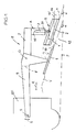
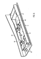
- Fig. 1 schematically shows a paver RF, which tows a screed E floating on a Planum P order from submitted V built-in pavement 43, z. B. consisting of a flat roadway 45 and a lateral hanging shoulder 44, to install in a working direction R.
- the screed E has a base board G with a below an angle of attack a relative to Planum P hired, base board screed plate 1, and each a vigbohlenfeste guide F for at least one displaceable perpendicular to the drawing plane Ausziehbohle A with an underside Ausziehbohlen-Glättblech 2.
- the screed E is coupled to the base beam G at 8 Switzerlandholmen 9 to tow points 5 of the paver RF, the tow points 5 individually or collectively in the direction of a double arrow 6 are up and down to change the attack angle a or for both Adjust the sides of the screed E differently.
- only one Ausziehbohle A could be provided, or could each Ausziehbohle be arranged on the front side of the base board G.
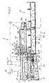
- each pull-out screed A (FIG. Fig. 2 ) At least two spaced apart in the displacement direction Z adjusting devices 3 arranged approximately vertically. Further, a separate Queme Whiles-adjustment device Q is provided between the adjustment 3 and the Ausziehbohlen-smoothing plate 2, for the hanging shoulder 44, as shown, the Ausziehbohlen-Glättblech 2 parallel to, for example, the Planum P and tilting in the working direction R pivot axis X to tilt.
- the adjusting devices 3 serve to set the rear bottom end point of the end edge of the screed screed plate 2 facing the base screed G 2, depending on the size of the angle of attack ⁇ , to the height position of the roadway 45.
- the Queme Trents- adjustment device Q is used to adjust the inclination of the hanging shoulder 44 relative to the roadway 45 and a bank angle 39 'of the Ausziehbohlen-Glättblechs 2, such that the outer end of the lower end edge of the Ausziehbohlen-Glättblechs 2 a lower height position in a Level 4 corresponding to the outer edge of the hanging shoulder 44 occupies.
- a transition 19 'between the lane 45 and the hanging shoulder 44 is in the pavement 43 by the imaginary intersection point 19 (in a view of the screed E from the rear, for example according to Fig. 2 ) defined between the Ausziehbohlen-smoothing plate 2 and the base screed plate 1.
- This point of intersection 19 should be located at a pull-out screed A mounted on the rear side of the basic screed G.
- Fig. 1 are at the outermost end of the trailing edge of the base screed Glättblechs 1 and is to keep stationary when changing the working width with respect to the base board, so that the width of the road 45 does not change impermissibly, but the width of the shoulder 44th
- the base board G can according to Fig. 2-4 have first and second baseboard parts G1, G2, which are connected in the center M of the base G in a joint 7 so that the baseboard parts G1, G2 are parallel to each other via a not shown adjustment (flat road 45) or bend relative to each other (road with roof profile).
- Each basic screed part G1, G2 has a box-like construction with inner and outer cheeks 15, 16 and a connection 8 for a drawbar 9.
- the extension screed A is displaceable parallel to the base screed G on the screed-fixed guide F via the pull-out guide structure A1 by means of, for example, a drive 14 (hydraulic cylinder) (displacement direction Z in FIG Fig. 2 ).
- a multipoint support K is provided between the pull-out guide structure A1 and the base board G. In Fig. 2 this is a three-point support which can be displaced even when the base board G is twisted or under installation forces from the slot V.
- the guide F comprises in the embodiment of Fig.
- the first guide device F1 ( Fig. 2 . Fig. 3 ) includes z. B. a between the cheeks 15, 16 of the Grundbohlenteils G1 fixed telescope telescope with an outer tube 26, an extendable intermediate tube 27 and an innermost telescopic tube 28.
- the telescopic tube 28 is fixed to an outer cheek 29 of the housing-like Auszieh Units Modell A1 (first support point P1).
- the second guide device F2 comprises a guide rod or a guide tube 12 'fixed parallel to the telescope tube in the base half G1 between the cheeks 15, 16. That in the Fig. 2 and 3 right end of the guide tube 12 'is held in a fixation 13, which is connected to the cheek 15, but from the cheek 15 and from one side of the base board G, ie, from the base board part G1, over the middle M of time in the other Grundbohlenteil G2 extends.
- a guide body 17 is slidably mounted on an inner cheek 18 of the Auszieh Operations Modell A1 and defines a second displaceable support point P2.
- the extension screed A (whose width seen in the sliding direction approximately corresponds to the width of the base screed part G1) should be able to be displaced over a stroke which corresponds approximately to the width of the screed part G1.
- the third guide device F3 comprises in the Fig. 2 and 3 a mounted on the rear side of Auszieh Operations Quilt A1, extending in the direction Z guide rail 10 and mounted on the outer cheek 16 of the Grundbohlenteils G1 torque arm 11 for the guide rail 10, which engages there, for example between rollers or sliding blocks.
- the guide contact between the torque arm 11 and the guide rail 10 defines a third support point P3.
- Fig. 2 is also another three-point support indicated.
- the guide body 17 'shown in dashed lines is guided on the inner cheek 18 of the Auszieh Operations Medical A1 inside the Grundbohlenteils G1 between the cheeks 15, 16 directly on the telescope tube or its telescope base 26, so that the second displaceable support point P2 is coaxial with the first support point P1.
- the third support point P3 of the pull-out guide structure A1 is in turn defined in the torque arm 11 on the cheek 16 of the base board part G1 by the guiding contact with the guide rail 10.
- the displacement stroke of the guide body 17 'and thus the Ausziehbohle A is limited in this case by the distance between the cheeks 15, 16 of the Grundbohlenteils G1, and thus shorter than half the plank width.
- the guide body 17, 17 ' is connected to the inner cheek 18 so that it engages through a cutout in the outer cheek 16 of the Grundbohlenteils G1, and the Auszieh Operationss Cook A1 can be retracted by this cutout in the Grundbohlenteil G1 until the outer cheek 29 abuts the outside of the outer cheek 16.
- the two per Ausziehbohle A provided adjusting 3 include z. B. two spaced in the displacement direction Z fferspindelvortechnischen 30, 31 ( Fig. 2 ), each of which also has a z. B. may have an accessible at the top of an upper Wirkend Vietnameses 40 mechanical actuator 26, but not must.
- the upper effect end point 40 is z. B. a mounted on the underside of Auszieh Equipments Quilt A1 support bracket.
- a lower action end point of each adjustment device 3 is defined by a bracket 35 mounted on a substantially horizontally disposed top 24 of a lower frame A2.
- the frame A2 is connected to the pull-out guide structure A1 via the screw-lock devices 30, 31, and additionally via in Fig. 2 and 3 indicated vertical guides 33 supported vertically movable.
- each screw spindle device 30, 31 comprises two screw spindles 32, between which the respective vertical guide 33 is arranged, which is connected to the Auszieh Operations Medical A1 above and the frame A2 below each either fixed or universal joints and telescopically adjustable.
- hydraulic cylinders (not shown) could also be used.
- the screw spindles 32 of each screw spindle device 30, 31 are provided with sprockets which are coupled via an endless chain 34 for synchronous movement. It is, preferably, for both fferspindelvortechnischen 30, 31, a common drive 20 arranged on the Auszieh Installations Geneva A1, for example, an electric motor or a hydraulic motor, the two screw spindles 30, 31 adjusted via endless chains 36 (gear train) synchronously and in each case via equal strokes. Alternatively, a separate drive 20 could be provided for each screw spindle 32 or for each screw spindle device 30, 31, for example a hydraulic motor or an electric geared motor.
- the Queme Trents-adjusting device Q is disposed in the frame A2 and includes a remotely actuable actuator 22 (for example, a hydraulic motor, hydraulic cylinder or an electric motor), the, z. B. (in Fig. 2 schematically indicated) is connected to at least one abutment 47 on the Ausziehbohlen-smoothing plate 2.
- the actuator 22 drives, for example via an angle gear or worm gear 37 at least one vertical screw 23. It could be provided alternatively a plurality of spaced apart in the direction of travel R actuators 22 or screw 23.
- the actuator 22 could also be a hydraulic cylinder, which is coupled via a link device or in a vertical arrangement directly to the one or more abutments 47.
- the Ausziehbohlen-smoothing plate 2 can be pivoted about a pivot axis X of a pivot joint 21 in the frame A2 to adjust the bank angle 39 '.
- the pivot axis X is in the illustrated embodiment, in which the Ausziehbohle A is mounted on the rear side of the base board G, for example at the outer end portion (end plate 46 in Fig. 4 ) of the frame A2 while the actuator 22 is mounted near the opposite end portion of the frame A2.
- the pivot axis X is substantially parallel to the Ausziehbohlen trowel plate 2 and parallel to the working direction R.
- the pivot joint 21 could alternatively be placed at a different location between the ends of the frame A2.
- an inserted panel V of laterally delimiting side shield 48 may be mounted on an end plate 46, or a screed extension member 49, e.g. with even greater working width to install.
- the drag resistance of the paving V exerts on the frame A2 forces, especially on the side plate 48 and / or the screed extension part 49. These forces are bypassing the Ausziehbohlen-Glättblechs 2 on a power transmission path in frame A2 via the vertical guides 33 and the adjusting 3 in the pullout guide structure A1 initiated.
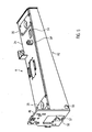
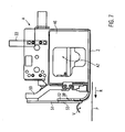
- the frame A2 of the Ausziehbohle A in the Fig. 5 . 6 . 7 vice versa has U-shaped cross section with open bottom 57 and carries on the top 24, the brackets 35. There are also an opening 54 and a bearing 54 for the actuator 22, 23 placed. Behind the end plate 46 bearing lugs 56 are arranged as part of the pivot joint 21 in the frame A2, in which, for. B. by an opening 55, at least one pivot axis X defining pin (not shown) can be mounted.
- the plate-like Ausziehbohlen-smoothness plate 2 has a adoptedode, bent-up skirt 38 'and carries a (welded and / or screwed) trough-shaped support frame 59, are mounted on the bearing eyes 58 as another part of the pivot joint 21, as well as the abutment 47 for the actuator 22nd
- the skirt 38 ' has an upper edge 52 which initially runs parallel to the screed plate 2 and then rises at an angle.
- a front wall 51 is mounted on arms 50, which engages with an oblique bottom edge 53 in front of the skirt 38 '(in working direction R) down, and absorbs forces from the V-fitting.
- each Ausziehbohle A could at the front of the base board G by means of a scaffold-fixed guide F and a Auszieh elements Industrial A1 analogous to Fig. 2 to 4 be mounted.
- the pivot axis X and the pivot joint 21 could be placed at the inner end portion of the sub-frame A2 or between the end portions.
- the actuator 22 is then positioned near the outer end region, for example.
- Fig. 4 takes the height of the frame A2 z. B. according to the maximum skew angle 39, 39 'of the Ausziehbohlen-Glättblechs 2 gradually from whose rear lower end edge in Fig. 3 at maximum cross slope with 2E, in rectilinear alignment with the base screed plate 1 and the rear lower end edge 1 E with 2E '(for a flat pavement 45) is indicated.
- Fig. 2 shows the transition 19 'between the lane 45 and the hanging shoulder 44.
- the transverse position of the transition 19' is defined by the imaginary intersection 19 between the rear lower end edge 2E of the transverse Abziehbohlen-Glättblechs 2 and the rear lower end edge 1 E of the screed Smoothing plate 1 defined.
- the intersection point 19 or transition 19 ' is to be kept stationary with changes in the working width of the screed E with respect to the base board G, so that the width of the roadway 45 does not vary undesirably. This is effected with an actuation of the adjusting devices 3 without actuation of the leveling adjustment device Q.
- a chopper blade 42 eg, an angle sensor, eg in subframe A2
- an altimeter not shown
- An angle sensor 48 for transmitting information about the angle of attack a of the screed E could also be connected to the control device C, and an odometer, z. B.
- the control device C may in turn be commandingly connected to the adjustment 3 and possibly also the Queme Trents-adjustment Q to in an automatic or semi-automatic sequence at Changes to the installation conditions (eg in the case of a variation of the working width), the adjustment devices 3 are actuated so synchronously that the point of intersection 19 remains stationary with respect to the base board G.
- an actuating device with switches or push buttons for controlling each Ausziehbohle A is provided. These buttons or switches can be operated individually by the operator or by the operator. The switch or button for driving the actuator 22 could be selectively locked. Upon release of its function, the control of the adjustment 3 with the button to move linked, such that upon actuation of the button or switch for moving the extension screed A, the required height adjustment is performed automatically.
- the speed of the pushing-out movement of the extending screed A should then be appropriately correlated with the speed of the height adjustment so that the point of intersection 19 remains stationary.
- the respective transverse position of the intersection point 19 can be defined for control operations in the control device C.
- control operations are also other, not explained procedures, z. B. also a fully automatic.
- Fig. 4 the Ausziehbohle A is in fully inserted position.
- the outer cheek 29 of the Ausziehbohle A is externally approximately at the outer cheek 16 of the Grundbohlenteils G1.
- the in Fig. 4 Not shown guide body 17 is retracted into the fixation 13 (position 18R, 17R).
- the torque arm 11 engages the other end of the guide rail 10.
- the base screed screed 1 is in working direction R before the Ausziehbohlen-screed plate 2, which is raised at the inner end.
- the frame A2 is moved by means of the adjusting 3 so far up that in Fig.
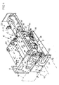
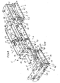
- FIG. 8 further embodiment of the screed E according to the invention differs from the embodiment of the Fig. 2 to 7 Mainly in that, for adjusting the bank angle 39 'of the Ausziehbohlen-Glättbleches 2 for forming a shoulder 44 is not the Ausziehbohlen-Glättblech 2 relative to the frame A2 in the pivot joint 21 is pivoted, but the Ausziehbohlen-Glättblech 2, preferably interchangeable, fixed to the frame A2 is mounted, and the frame A2 is pivoted together with the Ausziehbohlen-smoothing plate 2 in the pivot joint 21 by means of the actuators 22.
- the adjusting devices 3, 30, 31 of the extension screed A jointly act on an intermediate frame 61, on which the swivel joint 21 for the frame A2 is arranged, and on which the actuators 22 connected to the frame A2 also engage.
- the pivot joint 21 and the actuators 22 are disposed near the end portions, ie, the outer and inner ends of the frame A2 so as to position the adjusting devices 3, 31, 30 therebetween.
- a common drive 20 is mounted on the pull-out guide structure A1, which is drivingly connected via chain drives or gear trains 36 to the screw spindles of the adjusting devices 3, 30, 31.
- the multipoint support K for the respective pullout guide structure A1 is a three-point support with the first, second and third support points P1, P2 and P3.
- the first support point P1 is located in the outer cheek of the Aüszieh operationss Vietnamese A1 and where the telescopic tube 28 is mounted in the outer cheek 29.
- the second support point P2 is located in the guide member 17 which is fixed to the inner cheek 18 of Auszieh operationss réelle A1 and slidably guided on the guide rod or the guide tube 12 '.
- the guide rod 12 ' is fixed at the outer end in the outer cheek 16 of the Grundbohlenteils G1 and extends with its inner end over the center M of the base G out into the other Grundbohlenteil G2 to the there placed fixation 13, with the inner cheek 15th is connected to the Grundbohlenteils G1, so that the guide member 17 from the outer position on the inside of the outer cheek 16 of the Grundbohlenteils G1 is displaceable until approximately in contact with the fixation 13, and the stroke of the Ausziehbohle A in about half the width of Base board G corresponds.
- the third support point P3 is defined by the torque arm 11 mounted on the outer cheek of the base board G and the guide rail 10 mounted on the rear side of the pullout guide structure A1 by the engagement between the guide rail 10 and the torque arm 11.
- the first and second support points P1, P2 follow the sliding movement of the extension screed A, while the third support point P3 remains stationary with respect to the base screed G.
- the guide tube 12 ' is in working direction R relative to the telescope telescope with the telescopic base tube 26 between the inner and outer cheeks 16, 15 of the base screed part G1, the insectsteleskoprohr 27 and the telescopic tube 28.
- the guide tubes 12 'in the two Baseboard parts G1, G2 are also offset in working direction R relative to each other, as well as the drives 14, 12, that is, the hydraulic cylinders that extend through corresponding cutouts in the outer cheeks 16 and attack in the Auszieh Adjusts Quilt A1.
- the mounting plate 46 is provided on the in Fig. 8 the side plate 48 is mounted, which prevents installation; that the built-in material flows laterally beyond the set working width.
- the side plate 48 can be mounted on the mounting plate 46, not shown screed extension part, which then also carries a side plate 48 analog.
- the basic screed parts G1, G2 can be made of the in Fig. 8 shown, aligned positioning about the hinge 7 are bent relative to each other to form a roof profile in the lane 43.
- a device 62 of the base board G may be provided.
- a device 63 between the base board G and each terminal 8 of an in Fig. 8 Not shown Switzerlandholms provided to vary the attack angle of the screed relative to the towbar or connection 8, without adjusting the tow points 5 on the paver RF.
- the embodiment in Fig. 8 could be provided with a statically determined three-point support of the Auszieh Operations Cook A1, as explained with reference to the preceding embodiment, in which then a in Fig. 8 not shown guide body is guided displaceably on the telescopic base tube 26 of the telescope tube instead of the guide body 17 on the inner cheek 18 of Auszieh operations Cook A1.
- the first and second support points P1, P2 would be arranged in the axis of the tube telescope.
- the extension stroke of the Ausziehbohle A would be somewhat shorter than in the Fig. 8 shown three-point support.
- the transverse position of the transition 19, 19 ' is held stationary with respect to the base board G by changing the working width, that the adjusting devices 3, 30, 31 are adjusted in accordance with the sliding movement (drive 14, 12), namely during insertion of the Extending screed A by lifting the subframe 61, and when pushing out the Ausziehbohle A by lowering the subframe 61st
Claims (16)
- Poutre égaliseuse (E) pour finisseuse de routes (RF), avec
une poutre de base (G) et des poutres extensibles (A) qui, pour modifier la largeur de travail, sont supportées à l'avant ou à l'arrière, à l'aide d'une structure de guidage d'extension (A1), sur un guide (F) fixé à la poutre de base (G) et pourvu de dispositifs de guidage (F1, F2, F3), et qui sont aptes à coulisser dans un sens de coulissement (Z) parallèlement à la poutre de base (G) et par rapport à celle-ci, à l'aide d'entraînements (14, 12),
des tôles de lissage (1, 2) disposées en bas de la poutre de base (G) et des poutres extensibles (A),
des raccordements (8) disposés sur la poutre de base (G), pour des longerons (9) destinés à tirer de manière flottante la poutre égaliseuse (E) avec un angle d'attaque (α) des tôles de lissage (1, 2) par rapport à une plate-forme de chaussée (P),
un support à plusieurs points (K) qui est prévu entre la structure de guidage d'extension (A1) et la poutre de base (G) sur les dispositifs de guidage (F1, F2, F3),
un châssis (A2), dans la poutre extensible (A), qui comporte la tôle de lissage de poutre extensible (2), et
au moins deux dispositifs de réglage (3, 30, 31) qui sont espacés dans le sens de coulissement (Z) de la poutre extensible (A), qui sont aptes à être actionnés par l'intermédiaire d'au moins un entraînement (20), qui sont à peu près verticaux, qui agissent sur la structure de guidage d'extension (A1) et qui sont destinés au moins à régler la position en hauteur du châssis (A2) par rapport à la poutre de base (G),
étant précisé qu'il est prévu un dispositif de réglage d'inclinaison transversale (Q) à construction séparée des dispositifs de réglage (3, 30, 31), qui est pourvu d'au moins un entraînement et avec lequel un angle d'inclinaison d'accotement (39') est apte à être réglé, par rapport à la poutre de base (G), sur la poutre extensible (A), autour d'une articulation pivotante (21) avec un axe de pivotement (X) orienté au moins approximativement perpendiculairement par rapport au sens de coulissement (Z) et parallèlement à la tôle de lissage de poutre extensible (2), sur le châssis (A2) ou sur ladite tôle de lissage (2),
caractérisée en ce que les dispositifs de réglage (3, 30, 31) sont prévus entre la structure de guidage d'extension (A1) et le châssis (A2) de la poutre extensible (A), et en ce que le dispositif de réglage d'inclinaison transversale (Q) est disposé soit entre les dispositifs de réglage (3, 30, 31) et le châssis (A2) présentant la tôle de lissage de poutre extensible (2) fixe, soit entre le châssis (A2) présentant la tôle de lissage (2) inclinable transversalement et la tôle de lissage (2), et en ce que l'entraînement du dispositif de réglage d'inclinaison transversale est apte à être télécommandé. - Poutre égaliseuse selon la revendication 1, caractérisée en ce que l'articulation de pivotement (21) du dispositif de réglage d'inclinaison transversale (Q) est disposée soit entre la tôle de lissage de poutre extensible (2) et le châssis (A2), soit entre un châssis intermédiaire (61) reliant des points d'extrémité actifs inférieurs des dispositifs de réglage (3, 30, 31), et le châssis (A2), et en ce qu'il est prévu comme entraînement du dispositif de réglage d'inclinaison transversale (Q) au moins un actionneur (22) qui est espacé de l'articulation de pivotement (21) dans le sens de coulissement (Z) et qui est disposé soit entre le châssis (A2) et la tôle de lissage de poutre extensible (2), soit entre le châssis (A2) et le châssis intermédiaire (61).
- Poutre égaliseuse selon la revendication 1, caractérisée en ce que la tôle de lissage de poutre extensible (2) consiste en une plaque plane avec un tablier (38') situé à l'avant, dans le sens de travail, et dépassant sur un côté longitudinal, et en ce qu'il est prévu sur le châssis (A2), montée sur le côté avant dans le sens de travail (R), une paroi avant (51) qui s'étend de haut en bas en couvrant le tablier (38'), situé derrière, de la tôle de lissage de poutre extensible (2).
- Poutre égaliseuse selon la revendication 1, caractérisée en ce qu'il est prévu sur la tôle de lissage de poutre extensible (2) un châssis porteur (59) qui comporte des parties de l'articulation de pivotement (21) et au moins une butée (47) pour l'entraînement apte à être télécommandé, et en ce que le châssis (A2), qui présente de préférence une section transversale en U renversé avec un côté inférieur ouvert (57), porte d'autres parties de l'articulation de pivotement (21) et un support (54) pour l'entraînement.
- Poutre égaliseuse selon la revendication 1, caractérisée en ce que l'axe de pivotement (X) est défini par au moins un tourillon qui est introduit dans des parties de l'articulation de pivotement (21) dirigées l'une vers l'autre.
- Poutre égaliseuse selon la revendication 1, caractérisée en ce qu'une plaque de montage (46) pour une lame latérale (48) ou une rallonge de poutre (49) est fixée à l'extrémité extérieure du châssis (A2).
- Poutre égaliseuse selon la revendication 2, caractérisée en ce que dans la poutre extensible (A), l'articulation de pivotement (21) est disposée au niveau de la zone d'extrémité intérieure ou extérieure du châssis (A2) ou entre les deux, et de préférence dans la poutre extensible (A) montée à l'arrière de la poutre de base (G) l'actionneur (22) est disposé dans une zone d'extrémité dirigée vers le centre (M) de ladite poutre de base (G) et l'articulation de pivotement (21) est disposée dans la zone d'extrémité du châssis (A2) située à l'extérieur et opposée au centre (M) de la poutre de base (G).
- Poutre égaliseuse selon la revendication 2, caractérisée en ce que l'actionneur (22) comporte au moins un cylindre hydraulique orienté à peu près à la verticale par rapport au sens de coulissement (Z), ou un entraînement à broche (23) à commande hydraulique ou électrique, de préférence avec un engrenage angulaire ou un engrenage à vis sans fin.
- Poutre égaliseuse selon la revendication 2, caractérisée en ce qu'il est prévu entre la structure de guidage d'extension (A) et le châssis (A2) ou le châssis intermédiaire (61) des guides verticaux (33) qui sont de préférence associés fonctionnellement aux dispositifs de réglage (3, 30, 31).
- Poutre égaliseuse selon la revendication 4, caractérisée en ce que le côté inférieur du châssis (A2) et un bord supérieur (52) du tablier (38') de la tôle de lissage de poutre extensible (2) ont une forme inclinée qui va en montant vers le centre (M) de la poutre de base (G).
- Poutre égaliseuse selon la revendication 1, caractérisée en ce que la poutre extensible (A) est en appui par l'intermédiaire des dispositifs de réglage (3, 30, 31) au niveau de l'appui multipoint (K) qui est conçu comme un appui à trois points, fonctionnant sans force de serrage, avec trois points d'appui (P1, P2, P3), et dans lequel la structure de guidage d'extension (A) présente le premier point d'appui (P1) sur un flasque extérieur (29), à l'extérieur de la poutre de base (G), au niveau d'un tube télescopique (28) extensible hors d'un télescope tubulaire du dispositif de guidage (F1) fixé dans ladite poutre de base (G) ; le deuxième point d'appui (P2), coaxial par rapport au premier, sur un flasque intérieur (18), à l'intérieur de la poutre de base (G), dans un corps de guidage (17') guidé sur le télescope ; et le troisième point (P3) sur un rail de guidage (10) qui s'étend sur le côté arrière, à une certaine distance du dispositif de guidage (F1) et dans le sens d'extension sur la structure de guidage d'extension (A1), dans un appui de couple (11) fixé à la poutre de base (G), étant précisé que le flasque intérieur (18), quand la poutre extensible (A) est rétractée au maximum, est mobile sur le télescope jusqu'à un flasque intérieur (15) de la poutre de base (G) et que le troisième point d'appui (P3), sur une vue latérale de la poutre extensible (A), est décalé par rapport aux premier et second points d'appui coaxiaux (P1, P2).
- Poutre égaliseuse selon la revendication 1, caractérisée en ce que la poutre extensible (A) est en appui par l'intermédiaire des dispositifs de réglage (3, 30, 31) au niveau de l'appui multipoint (K) qui est conçu comme un appui à trois points, fonctionnant sans force de serrage, avec trois points d'appui (P1, P2, P3), et dans lequel la structure de guidage d'extension (A1) présente le premier point d'appui (P1) sur un flasque extérieur (29), à l'extérieur de la poutre de base (G), au niveau d'un tube télescopique (28) extensible hors d'un télescope tubulaire du dispositif de guidage (F1) fixé à ladite poutre de base (G) ; le deuxième point d'appui (P2) sur un flasque intérieur (18) de la poutre extensible (A), à l'intérieur de la poutre de base (G), au niveau d'un corps de guidage (17) qui est guidé coulissant sur un tube de guidage (12') du dispositif de guidage (F2) parallèle au télescope, décalé perpendiculairement au sens de coulissement (Z) et fixé dans la poutre de base (G) ; et le troisième point d'appui (P3), décalé par rapport aux premier et deuxième points d'appui (P1, P2), sur un rail de guidage (10) qui est fixé au côté arrière de la structure de guidage d'extension (A1) et qui s'étend dans le sens de coulissement (Z), dans un appui de couple (11) du dispositif de guidage (F3) fixé dans la poutre de base (G), étant précisé que le tube de guidage (12') est immobilisé, à l'extrémité intérieure, dans la poutre de base (G) dans une fixation (13) (A) décalée par rapport au côté de la poutre extensible (A) au-delà du centre (M) de la poutre de base (G) vers l'autre côté du centre (M), et que le corps de guidage (17), quand la poutre extensible (A) est rétractée au maximum, est mobile sur le tube de guidage (12') au-delà du centre (M) à peu près jusqu'à la fixation (13).
- Poutre égaliseuse selon la revendication 2, caractérisée en ce qu'il est prévu sur la poutre extensible (A) un appareil de mesure d'inclinaison transversale (42) et/ou un appareil de mesure de hauteur pour la hauteur relative entre la tôle de lissage de poutre extensible (2) et la tôle de lissage de poutre de base (1) et/ou un appareil de mesure de course dans ou sur l'actionneur (22) et/ou dans ou sur les dispositifs de réglage (3, 30, 31) et/ou les entraînements (14, 12), qui sont reliés, suivant une relation de transmission de signaux, à un dispositif de commande (C) pour des fonctions de poutre égaliseuse.
- Poutre égaliseuse selon la revendication 1, caractérisée en ce que les dispositifs de réglage (3, 30, 31) de la poutre extensible (A), conçus de préférence comme des broches filetées ou des paires de broches filetées, comportent un entraînement commun (20), de préférence un moteur hydraulique ou un moteur électrique qui est disposé, de préférence de manière à peu près centrale, entre les dispositifs de réglage (3, 30, 31) sur le châssis (12) ou le châssis intermédiaire (61) et qui est relié aux dispositifs de réglage en vue de l'actionnement synchrone de ceux-ci par l'intermédiaire de trains d'engrenages et/ou de transmissions (36).
- Procédé pour poser un revêtement de chaussée (43) comportant une chaussée (45) et au moins un accotement latéral (44) incliné transversalement, avec une largeur de travail variable sur une plate-forme de chaussée (P), avec une poutre égaliseuse (E) qui comporte une poutre de base (G) avec une tôle de lissage de poutre de base (1), et, pour le réglage de la largeur de travail, à l'avant ou à l'arrière sur la poutre de base (G), au moins une poutre extensible (A) qui est apte à coulisser parallèlement et par rapport à la poutre de base, qui présente une structure de guidage d'extension (A1) sur un guide (F) solidaire de la poutre de base et pourvu de plusieurs dispositifs de guidage (F1, F2, F2), et qui est pourvue d'une tôle de lissage de poutre extensible (2) disposée sur un châssis (A2) et destinée à former l'accotement (44) en dehors d'une transition (19') entre la chaussée (45) et l'accotement (44), et dans la poutre extensible (A), entre la poutre de base (G), au moins deux dispositifs de réglage (3, 30, 31), espacés dans le sens de coulissement (Z) et agissant sur la structure de guidage d'extension (A1), pour la position en hauteur de la tôle de lissage de poutre extensible (2) par rapport à la tôle de lissage de poutre de base (1), étant précisé que pour former l'accotement (44), on règle un angle d'inclinaison transversal 39') sur la tôle de lissage de poutre extensible (2) par rapport à la poutre de base (G), à l'aide d'un dispositif de réglage d'inclinaison verticale (Q) de la poutre extensible (A) qui est séparé par sa construction et par sa fonction des dispositifs de réglage (3, 30, 31), caractérisé par les étapes suivantes :on règle l'angle d'inclinaison transversale (39') de la tôle de lissage de poutre extensible (2) soit par rapport au châssis (A2), soit avec le châssis (A2) et par rapport à la structure de guidage d'extension (A2), à l'aide du dispositif de réglage d'inclinaison transversale apte à être télécommandé, eton maintient fixe une position transversale de la transition (19') entre la chaussée (45) et l'accotement (44) par rapport à la poutre de base (G) lors d'une variation de la largeur de travail du revêtement de chaussée (43) grâce à un coulissement de la poutre extensible (A), en réglant globalement en même temps la position en hauteur de la tôle de lissage de poutre extensible (2) par rapport à la structure de guidage d'extension (A1) à l'aide des dispositifs de réglage (3, 30, 31).
- Procédé selon la revendication 15, caractérisé en ce que même lors d'une modification de l'angle d'inclinaison transversale (39), on maintient fixe la position transversale de la transition (19') par rapport à la poutre de base (G) grâce à un réglage globalement simultané, par ajustement, de la position en hauteur de la tôle de lissage de poutre extensible (2) par rapport à la structure de guidage d'extension (A2).
Priority Applications (4)
| Application Number | Priority Date | Filing Date | Title |
|---|---|---|---|
| EP08021844A EP2199467B1 (fr) | 2008-12-16 | 2008-12-16 | Poutre égaliseuse et procédé destiné à la fabrication d'un revêtement de chaussée |
| US12/616,813 US8128314B2 (en) | 2008-12-16 | 2009-11-12 | Paving screed and a method for laying a paving mat |
| JP2009268473A JP4875136B2 (ja) | 2008-12-16 | 2009-11-26 | 舗装スクリード、及び舗装マットを敷設する方法 |
| CN2009102542672A CN101812823B (zh) | 2008-12-16 | 2009-12-14 | 铺路刮板及用于铺设铺路垫块的方法 |
Applications Claiming Priority (1)
| Application Number | Priority Date | Filing Date | Title |
|---|---|---|---|
| EP08021844A EP2199467B1 (fr) | 2008-12-16 | 2008-12-16 | Poutre égaliseuse et procédé destiné à la fabrication d'un revêtement de chaussée |
Publications (2)
| Publication Number | Publication Date |
|---|---|
| EP2199467A1 EP2199467A1 (fr) | 2010-06-23 |
| EP2199467B1 true EP2199467B1 (fr) | 2011-07-13 |
Family
ID=40613024
Family Applications (1)
| Application Number | Title | Priority Date | Filing Date |
|---|---|---|---|
| EP08021844A Active EP2199467B1 (fr) | 2008-12-16 | 2008-12-16 | Poutre égaliseuse et procédé destiné à la fabrication d'un revêtement de chaussée |
Country Status (4)
| Country | Link |
|---|---|
| US (1) | US8128314B2 (fr) |
| EP (1) | EP2199467B1 (fr) |
| JP (1) | JP4875136B2 (fr) |
| CN (1) | CN101812823B (fr) |
Families Citing this family (26)
| Publication number | Priority date | Publication date | Assignee | Title |
|---|---|---|---|---|
| PL2325390T5 (pl) * | 2009-10-20 | 2019-12-31 | Joseph Vögele AG | Deska równająca i zespół maszynowy do budowy dróg |
| US8371769B2 (en) * | 2010-04-14 | 2013-02-12 | Caterpillar Trimble Control Technologies Llc | Paving machine control and method |
| DE202010012456U1 (de) * | 2010-09-10 | 2011-12-12 | Smg Sportplatzmaschinenbau Gmbh | Einbaufertiger mit einem Vorratsbehälter |
| CN102383363B (zh) * | 2011-08-18 | 2013-07-24 | 中联重科股份有限公司 | 摊铺机及用于其的浮动挡料系统 |
| CN102409596B (zh) * | 2011-08-18 | 2014-02-12 | 中联重科股份有限公司 | 伸缩式熨平板结构和摊铺机 |
| US8491221B1 (en) * | 2011-11-03 | 2013-07-23 | Asphalt Joint Compactor, LLC | Compacting screed extension for paving |
| CN102518027B (zh) * | 2011-12-14 | 2013-11-06 | 中联重科股份有限公司 | 一种搓平装置及滑模摊铺机 |
| US8764342B1 (en) | 2013-02-14 | 2014-07-01 | Caterpillar Paving Products Inc. | System and method for mounting wear bar to screed assembly |
| US8864410B1 (en) | 2013-04-03 | 2014-10-21 | Caterpillar Paving Products Inc. | Screed walkway |
| US9222227B2 (en) * | 2014-02-05 | 2015-12-29 | Caterpillar Paving Products Inc. | Extendable screed height adjusting system with angle of attack adjustment |
| CN104120643B (zh) | 2014-08-06 | 2016-08-24 | 戴纳派克(中国)压实摊铺设备有限公司 | 伸缩熨平板及其摊铺机 |
| US9534348B2 (en) | 2015-02-16 | 2017-01-03 | Caterpillar Paving Products Inc. | Paver transition mark reduction |
| US9903076B2 (en) * | 2016-04-14 | 2018-02-27 | Dan Mohr | Paver extension bracket device |
| US10358779B2 (en) * | 2016-06-27 | 2019-07-23 | Carlson Paving Products, Inc. | Apparatus and method for a screed extension control system |
| US10633805B2 (en) * | 2018-03-30 | 2020-04-28 | Caterpillar Trimble Control Technologies Llc | Grade and slope lockout for extender movement of construction machine |
| US10480132B1 (en) | 2018-08-01 | 2019-11-19 | Caterpillar Paving Products Inc. | Fixed screed power take-off for improved performance |
| US11293149B2 (en) * | 2019-03-08 | 2022-04-05 | Caterpillar Paving Products Inc. | Stiffened screed extender tube |
| US10844556B2 (en) * | 2019-03-21 | 2020-11-24 | Caterpillar Paving Products Inc. | Screed extension for a main screed frame of a paving machine |
| US11162233B2 (en) * | 2019-12-05 | 2021-11-02 | Wirtgen Gmbh | Adjustable width mold |
| US11753778B2 (en) * | 2020-08-20 | 2023-09-12 | Idaho Asphalt Supply, Inc. | Adjustable paving machine |
| US20220162811A1 (en) * | 2020-11-23 | 2022-05-26 | Caterpillar Paving Products Inc. | Power activated steering guide |
| US11746480B2 (en) * | 2021-05-28 | 2023-09-05 | Caterpillar Paving Products Inc. | System, apparatus, and method for controlling screed extender of paving machine |
| US11795631B2 (en) * | 2021-06-22 | 2023-10-24 | Caterpillar Paving Products Inc. | Linkage system for screed extension |
| US20230074055A1 (en) * | 2021-09-08 | 2023-03-09 | Caterpillar Paving Products Inc. | Optimum screed angle of attack setting and automatic adjustment |
| CN115323870B (zh) * | 2022-08-03 | 2023-08-01 | 民航机场建设工程有限公司 | 机场道面超平卷材过渡层砂浆找平机械及施工找平方法 |
| CN117436183B (zh) * | 2023-12-21 | 2024-03-05 | 湖南大学 | 深厚软土区桥梁、市政道路与邻近服务区同步施工方法 |
Family Cites Families (25)
| Publication number | Priority date | Publication date | Assignee | Title |
|---|---|---|---|---|
| US592489A (en) * | 1897-10-26 | Hand corn-planter | ||
| CH488863A (de) | 1968-05-21 | 1970-04-15 | Trachsel Franz | Vorrichtung zur stufenlosen Verstellung der Arbeitsbreite von Strassenfertigern für den Bau von Schwarzdecken und Betonbelägen |
| DE2709435C3 (de) * | 1977-03-04 | 1984-09-20 | Joseph Vögele AG, 6800 Mannheim | Einbaubohle |
| JPS54102031A (en) * | 1978-01-30 | 1979-08-11 | Nippon Road | Device for finishing surface of curved road |
| JPS57168510A (en) * | 1981-04-09 | 1982-10-16 | Nec Corp | Mos amplifying circuit |
| US4379653A (en) | 1981-06-01 | 1983-04-12 | White Consolidated Industries, Inc. | Asphalt paver with telescoping screed |
| DE3150031A1 (de) * | 1981-12-17 | 1983-06-23 | H. Stoll Gmbh & Co, 7410 Reutlingen | Hochflexibles isoliertes elektrisches kabel |
| IT1176643B (it) * | 1984-09-04 | 1987-08-18 | Simesa Spa | Dispositivo per controllare la pressione esercitata dal gruppo livellatore vibrante di una macchina vibrofinitrice per pavimentazioni stradali |
| JPH02144008A (ja) * | 1988-11-25 | 1990-06-01 | Matsushita Electric Ind Co Ltd | 厨房装置 |
| DE9211854U1 (de) | 1992-09-03 | 1994-02-24 | Voegele Ag J | Deckenfertiger |
| US5568992A (en) | 1995-05-19 | 1996-10-29 | Caterpillar Paving Products Inc. | Screed control system for an asphalt paver and method of use |
| JP2949094B2 (ja) * | 1997-10-20 | 1999-09-13 | 範多機械株式会社 | 舗装機におけるスクリード装置 |
| US5924819A (en) | 1998-01-23 | 1999-07-20 | Caterpillar Paving Products | Linkage mechanism for an extendable asphalt paver screed |
| DE19821090A1 (de) * | 1998-05-12 | 1999-12-02 | Abg Allg Baumaschinen Gmbh | Straßenfertiger |
| US6056474A (en) * | 1998-05-29 | 2000-05-02 | Caterpillar Inc. | Height control mechanism for strike-off plate of an asphalt paver screed assembly |
| US6179520B1 (en) * | 1998-07-31 | 2001-01-30 | Gary Cochran | Earth compacting machine |
| JP2000120016A (ja) * | 1998-10-16 | 2000-04-25 | Handa Kikai Kk | 舗装機におけるスクリード装置 |
| US6227761B1 (en) * | 1998-10-27 | 2001-05-08 | Delaware Capital Formation, Inc. | Apparatus and method for three-dimensional contouring |
| DE29903338U1 (de) | 1999-02-24 | 1999-05-12 | Voegele Ag J | Bohle |
| US6273636B1 (en) * | 1999-10-08 | 2001-08-14 | Blaw-Knox Construction Equipment Corporation | Edge-forming device for a screed assembly |
| US20020106243A1 (en) * | 2001-01-31 | 2002-08-08 | Rahn Christopher W. | Berm hinge |
| RU2347033C2 (ru) | 2003-03-07 | 2009-02-20 | Блау-Нокс Констракшн Эквипмент Корпорейшн | Выдвижное разравнивающее устройство для самоходного транспортного средства для строительства дорожных покрытий |
| ATE412800T1 (de) * | 2006-04-13 | 2008-11-15 | Voegele Ag J | Strassenfertiger |
| US7909534B1 (en) * | 2007-07-31 | 2011-03-22 | Astec Industries, Inc. | Apparatus and method for endgate with angle adjustment |
| EP2199466B1 (fr) * | 2008-12-16 | 2011-07-13 | Joseph Vögele AG | Procédé destiné à l'insertion d'un revêtement de chaussée |
-
2008
- 2008-12-16 EP EP08021844A patent/EP2199467B1/fr active Active
-
2009
- 2009-11-12 US US12/616,813 patent/US8128314B2/en active Active
- 2009-11-26 JP JP2009268473A patent/JP4875136B2/ja active Active
- 2009-12-14 CN CN2009102542672A patent/CN101812823B/zh active Active
Also Published As
| Publication number | Publication date |
|---|---|
| JP4875136B2 (ja) | 2012-02-15 |
| US8128314B2 (en) | 2012-03-06 |
| CN101812823B (zh) | 2012-07-04 |
| US20100150651A1 (en) | 2010-06-17 |
| JP2010144504A (ja) | 2010-07-01 |
| CN101812823A (zh) | 2010-08-25 |
| EP2199467A1 (fr) | 2010-06-23 |
Similar Documents
| Publication | Publication Date | Title |
|---|---|---|
| EP2199467B1 (fr) | Poutre égaliseuse et procédé destiné à la fabrication d'un revêtement de chaussée | |
| EP2218824B1 (fr) | Poutre lisseuse | |
| DE19836269C1 (de) | Straßenfertiger | |
| EP2169117B1 (fr) | Finisseur | |
| EP2845952B1 (fr) | Machine à coffrage glissant, et procédé d'adaptation de la largeur d'une poutre dameuse | |
| EP2395151B1 (fr) | Ensemble poutre lisseuse pour machine d'asphaltage | |
| EP2428614B1 (fr) | Finisseuse mobile | |
| DE102015006250B4 (de) | Anbaubohleneinheit für einen Straßenfertiger und Straßenfertiger mit einer solchen Anbaubohleneinheit | |
| DE10155507B4 (de) | Fertiger zum bodenseitigen Einbau von Schichten für Straßen od. dgl. | |
| WO2018033516A1 (fr) | Finisseur de talus | |
| EP3686345B1 (fr) | Finisseuse de route pourvue de déflecteur de matériau pivotant | |
| EP3498913B1 (fr) | Finisseuse de route pourvue d'un châssis pouvant être relevé | |
| EP2325393A1 (fr) | Procédé et finisseuse de route pour la fabrication d'un revêtement de route | |
| DE102005047096B3 (de) | Höhenverstellbares Seitenschild für Einbaubohle eines Straßenfertigers | |
| EP1179636A1 (fr) | Finisseuse et procédé de pavage | |
| EP3498915B1 (fr) | Finisseuse de route pourvue de châssis pouvant être relevé | |
| EP3382098A1 (fr) | Finisseuse de route comprenant un dispositif de retenue destiné à porter et à positionner une unité de capteur | |
| EP1239082B1 (fr) | Poutre lisseuse extensible pour un finisseur | |
| EP3575491B1 (fr) | Finisseuse de route avec plaque de limitation d'extension | |
| EP3988714A1 (fr) | Système de tôles de canal pour un finisseur de route | |
| EP3135815A1 (fr) | Table de lissage pour un finisseur | |
| DE19827902B4 (de) | Einbaubohle | |
| EP4144916B1 (fr) | Agencement de poutre lisseuse pour une finisseuse de route | |
| WO2017001388A1 (fr) | Poutre lisseuse | |
| DE102022124731A1 (de) | Automatisches mechanisches system zum positionieren der abziehbohle in der anfangspflastertiefe |
Legal Events
| Date | Code | Title | Description |
|---|---|---|---|
| PUAI | Public reference made under article 153(3) epc to a published international application that has entered the european phase |
Free format text: ORIGINAL CODE: 0009012 |
|
| 17P | Request for examination filed |
Effective date: 20090713 |
|
| AK | Designated contracting states |
Kind code of ref document: A1 Designated state(s): AT BE BG CH CY CZ DE DK EE ES FI FR GB GR HR HU IE IS IT LI LT LU LV MC MT NL NO PL PT RO SE SI SK TR |
|
| AX | Request for extension of the european patent |
Extension state: AL BA MK RS |
|
| GRAP | Despatch of communication of intention to grant a patent |
Free format text: ORIGINAL CODE: EPIDOSNIGR1 |
|
| AKX | Designation fees paid |
Designated state(s): DE GB IT |
|
| RAP1 | Party data changed (applicant data changed or rights of an application transferred) |
Owner name: JOSEPH VOEGELE AG |
|
| GRAS | Grant fee paid |
Free format text: ORIGINAL CODE: EPIDOSNIGR3 |
|
| GRAA | (expected) grant |
Free format text: ORIGINAL CODE: 0009210 |
|
| AK | Designated contracting states |
Kind code of ref document: B1 Designated state(s): DE GB IT |
|
| REG | Reference to a national code |
Ref country code: GB Ref legal event code: FG4D Free format text: NOT ENGLISH |
|
| RAP2 | Party data changed (patent owner data changed or rights of a patent transferred) |
Owner name: JOSEPH VOEGELE AG |
|
| REG | Reference to a national code |
Ref country code: DE Ref legal event code: R096 Ref document number: 502008004172 Country of ref document: DE Effective date: 20110908 |
|
| PLBE | No opposition filed within time limit |
Free format text: ORIGINAL CODE: 0009261 |
|
| STAA | Information on the status of an ep patent application or granted ep patent |
Free format text: STATUS: NO OPPOSITION FILED WITHIN TIME LIMIT |
|
| 26N | No opposition filed |
Effective date: 20120416 |
|
| REG | Reference to a national code |
Ref country code: DE Ref legal event code: R097 Ref document number: 502008004172 Country of ref document: DE Effective date: 20120416 |
|
| PGFP | Annual fee paid to national office [announced via postgrant information from national office to epo] |
Ref country code: DE Payment date: 20221223 Year of fee payment: 15 |
|
| P01 | Opt-out of the competence of the unified patent court (upc) registered |
Effective date: 20230524 |
|
| PGFP | Annual fee paid to national office [announced via postgrant information from national office to epo] |
Ref country code: GB Payment date: 20231218 Year of fee payment: 16 |
|
| PGFP | Annual fee paid to national office [announced via postgrant information from national office to epo] |
Ref country code: IT Payment date: 20231227 Year of fee payment: 16 |