EP2199152A1 - Umschaltverfahren des Beleuchtungsmodus von Kraftfahrzeugscheinwerfern - Google Patents
Umschaltverfahren des Beleuchtungsmodus von Kraftfahrzeugscheinwerfern Download PDFInfo
- Publication number
- EP2199152A1 EP2199152A1 EP09179275A EP09179275A EP2199152A1 EP 2199152 A1 EP2199152 A1 EP 2199152A1 EP 09179275 A EP09179275 A EP 09179275A EP 09179275 A EP09179275 A EP 09179275A EP 2199152 A1 EP2199152 A1 EP 2199152A1
- Authority
- EP
- European Patent Office
- Prior art keywords
- projectors
- visibility
- threshold
- range
- backscattering
- Prior art date
- Legal status (The legal status is an assumption and is not a legal conclusion. Google has not performed a legal analysis and makes no representation as to the accuracy of the status listed.)
- Granted
Links
Images


Classifications
-
- B—PERFORMING OPERATIONS; TRANSPORTING
- B60—VEHICLES IN GENERAL
- B60Q—ARRANGEMENT OF SIGNALLING OR LIGHTING DEVICES, THE MOUNTING OR SUPPORTING THEREOF OR CIRCUITS THEREFOR, FOR VEHICLES IN GENERAL
- B60Q1/00—Arrangement of optical signalling or lighting devices, the mounting or supporting thereof or circuits therefor
- B60Q1/02—Arrangement of optical signalling or lighting devices, the mounting or supporting thereof or circuits therefor the devices being primarily intended to illuminate the way ahead or to illuminate other areas of way or environments
- B60Q1/04—Arrangement of optical signalling or lighting devices, the mounting or supporting thereof or circuits therefor the devices being primarily intended to illuminate the way ahead or to illuminate other areas of way or environments the devices being headlights
- B60Q1/14—Arrangement of optical signalling or lighting devices, the mounting or supporting thereof or circuits therefor the devices being primarily intended to illuminate the way ahead or to illuminate other areas of way or environments the devices being headlights having dimming means
- B60Q1/1415—Dimming circuits
- B60Q1/1423—Automatic dimming circuits, i.e. switching between high beam and low beam due to change of ambient light or light level in road traffic
-
- B—PERFORMING OPERATIONS; TRANSPORTING
- B60—VEHICLES IN GENERAL
- B60Q—ARRANGEMENT OF SIGNALLING OR LIGHTING DEVICES, THE MOUNTING OR SUPPORTING THEREOF OR CIRCUITS THEREFOR, FOR VEHICLES IN GENERAL
- B60Q1/00—Arrangement of optical signalling or lighting devices, the mounting or supporting thereof or circuits therefor
- B60Q1/02—Arrangement of optical signalling or lighting devices, the mounting or supporting thereof or circuits therefor the devices being primarily intended to illuminate the way ahead or to illuminate other areas of way or environments
- B60Q1/04—Arrangement of optical signalling or lighting devices, the mounting or supporting thereof or circuits therefor the devices being primarily intended to illuminate the way ahead or to illuminate other areas of way or environments the devices being headlights
- B60Q1/06—Arrangement of optical signalling or lighting devices, the mounting or supporting thereof or circuits therefor the devices being primarily intended to illuminate the way ahead or to illuminate other areas of way or environments the devices being headlights adjustable, e.g. remotely-controlled from inside vehicle
- B60Q1/08—Arrangement of optical signalling or lighting devices, the mounting or supporting thereof or circuits therefor the devices being primarily intended to illuminate the way ahead or to illuminate other areas of way or environments the devices being headlights adjustable, e.g. remotely-controlled from inside vehicle automatically
- B60Q1/085—Arrangement of optical signalling or lighting devices, the mounting or supporting thereof or circuits therefor the devices being primarily intended to illuminate the way ahead or to illuminate other areas of way or environments the devices being headlights adjustable, e.g. remotely-controlled from inside vehicle automatically due to special conditions, e.g. adverse weather, type of road, badly illuminated road signs or potential dangers
-
- B—PERFORMING OPERATIONS; TRANSPORTING
- B60—VEHICLES IN GENERAL
- B60Q—ARRANGEMENT OF SIGNALLING OR LIGHTING DEVICES, THE MOUNTING OR SUPPORTING THEREOF OR CIRCUITS THEREFOR, FOR VEHICLES IN GENERAL
- B60Q2300/00—Indexing codes for automatically adjustable headlamps or automatically dimmable headlamps
- B60Q2300/30—Indexing codes relating to the vehicle environment
- B60Q2300/31—Atmospheric conditions
- B60Q2300/312—Adverse weather
Definitions
- the present invention relates to a method of automatically switching projectors capable of emitting a light beam for a motor vehicle from one lighting mode to another lighting mode, and an automatic switching device for carrying out said method.
- the object of the present invention is a method of automatically switching projectors capable of emitting a light beam for a motor vehicle from one lighting mode to another lighting mode, which makes it possible to reactivate the switching to the road position of the light mode. floodlighting, as soon as the disturbance phenomenon of visibility is weaker, see disappears completely.
- the fact of increasing the range of illumination of the light beam of the projectors with respect to a maximum authorized position makes it possible to better illuminate the phenomenon disturbing visibility so as to make possible the measurement of backscatter. If it has gone down or disappeared, the headlamps can be re-switched to the road position. So we can reactivate the switching position code position mode position.
- a third subject of the invention relates to a computer program product comprising one or more instruction sequences executable by an information processing unit, the execution of said instruction sequences enabling implementation of the method. according to any one of the preceding features.
- motor vehicle any vehicle comprising a motor.
- the method further comprises the additional step of allowing automatic switching of the projectors from the first lighting mode to the second lighting mode when the backscattering reaches the first determined threshold T1 (step ON_COM1 ).
- the method further comprises the step of switching the projectors in the first lighting mode MOD_C in order to reduce a backscattering of the light beam FX of the PJ projectors on a visibility-disruptive phenomenon. F when the detected backscattering reaches a third visibility threshold T3.
- the method further comprises the additional step of prohibiting the automatic switching of projectors from the first illumination mode to the second illumination mode when the detected backscattering reaches a third visibility threshold T3 (step OFF_COM1).
- the method comprises these two additional steps.
- a first step 1) when the projectors PJ are in a first mode of illumination MOD_C, one detects a backscattering of the light beam FX of the projectors PJ on a disturbing phenomenon of visibility F.
- the disturbing phenomenon of visibility F may be for example fog.
- the method can be applied to other visibility-impairing phenomena, that is to say any phenomenon F which creates an atmospheric disturbance so as to cause a loss of visibility for a user of the vehicle V, such as heavy rain or splashing water (called Gischt in German or Spray in English) generated by vehicles ahead of the vehicle V considered, in one example.
- any phenomenon F which creates an atmospheric disturbance so as to cause a loss of visibility for a user of the vehicle V, such as heavy rain or splashing water (called Gischt in German or Spray in English) generated by vehicles ahead of the vehicle V considered, in one example.
- the first lighting mode is the mode in code position MOD_C (dipped headlights on).
- the PJ projectors when the PJ projectors are in the first MOD_C lighting mode, it means that one is either in an illuminated environment with or without presence of a disturbing phenomenon of visibility F, or in an unlit environment with presence a disturbing phenomenon of visibility F, either in an environment with the presence of a vehicle in front (crossed or followed) with or without presence of disturbance phenomenon of visibility.
- a disturbance phenomenon of visibility F such as fog is taken as a non-limiting example.
- the step of detecting a backscattering is performed by measuring a visibility distance D (step DETECT_R (D)).
- the measurement of a visibility distance D makes it possible to determine if there is a disturbance phenomenon of visibility F and what is its density. Thus, the backscattering of the light beam FX on said visibility disturbing phenomenon is known.
- the step of detecting a backscattering is performed by analyzing a gray level curve obtained from an acquired image I of the environment of the motor vehicle (step DETECT_R (I)).
- First step determination of a gray level curve.
- a first substep 1a at least one image is acquired by pairing the camera of the vehicle V.
- the video camera CAM being placed, in the example taken, in front of the vehicle V, the acquired image I corresponds to the environment E of the vehicle V being in the field of the CAM camera and therefore to the front of the vehicle V. It will therefore detect a disturbing phenomenon F such that the fog at the front of the vehicle V.
- the light emanating from a light beam FX emitted from one of the projectors PJ is diffused in the presence of particles of the fog F suspended in the atmosphere.
- the wavelength of this light beam being compatible with the analysis spectrum of the CAM camera, and the constituent particles of the fog F being in the field of view of the CAM camera, it is then possible to capture an image integrating the light scattered in the fog F.
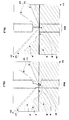
- the Fig. 6 shows a schematic example of acquired image I at night in the absence of fog F
- the Fig. 7 shows a schematic example of an acquired image I at night in the presence of fog F.
- On the abscissa of an image I are represented the columns Cn of this image I, while on the ordinate are represented lines Ln of this image I.
- the white part represents the light scattered at night with the light beam FX, while the diagonal hatched portion denoted N represents the environment E, here at the front of the vehicle V, in the field of the CAM camera not illuminated by the light beam FX.
- the landscape P bordering the road is represented in dotted line because it is veiled by the fog F schematically represented.
- At least one point of interest H is determined in an acquired image I of the environment E of the vehicle V.
- this point of interest is located on the horizon line H in acquired image I.
- the horizon line H from a calculation of the vanishing point PF in the image I resulting from the intersection of the drawing of the white lines L1 and L2 on the road, or else determine it from attitude sensors.
- the horizon line H is represented on both Fig. 6 and 7 .
- the horizon line H is dashed because it is veiled because of the fog F.
- a region of interest ROI is determined in said image I.
- the reference point PR is the vanishing point PF as illustrated in FIGS. Fig. 6 and FIG. 7 .
- the vanishing point PF is centered on the image I acquired.
- image I of format 640 * 480 its abscissa PFx is located at 320 pixels, its ordinate PFy is on the horizon line H.
- the optical axis of the camera CAM is parallel to the direction of vehicle V.
- the region of interest ROI is determined in said image I as a function of the steering angle ⁇ of the vehicle V.
- the region of interest ROI is shifted to the right on the image I, whereas when the steering wheel angle ⁇ is negative, the region of interest ROI is shifted to the left
- the steering wheel angle ⁇ is equal to 10 °
- the ROI region of interest is shifted 30 pixels to the right with respect to the reference point PR, and is thus centered on a new one. reference point of 320 + 30 pixels.
- the region of interest ROI is shifted to the right on the image 1 (the direction of the road is to the right), whereas when the steering angle c is less than -15 °, the ROI region of interest is shifted to the left on the image I (the direction of the road goes to the left).
- the ROI region of interest is shifted 54 pixels to the left from the PR reference point, and so is centered on a new reference point of 320 -54 pixels.
- the fact of determining the position of the region of interest ROI (and more particularly its position relative to the abscissa as described above) in the acquired image I as a function of the steering angle ⁇ allows to take into account the direction of the road and thus to avoid obstacles such as embankments, trees, etc. located in front of the vehicle when the road is winding.
- the region of interest ROI is thus more homogeneous.
- a gray level curve CL is determined from said region of interest ROI.
- this gray level curve CL is determined in the following manner. For each line Ln of the acquired image I, only the pixels of the region of interest ROI are taken into account and a combination of pixels Px is applied so as to obtain a value GR for each line, this value GR being for example, a gray level value in the case of a video image (as described later).
- the combination is the median value of the gray levels of each pixel Px of the line Ln considered.
- the advantage of the median is to estimate the average value of the gray levels while avoiding the noise problems in the image I.
- a first example of grayscale curve CL1 is illustrated on the Fig. 8 in the case where there is no fog F, and a second example of grayscale curve CL2 is illustrated on the Fig. 9 in the case where there is fog F.
- a gray level curve CL may be, in non-limiting embodiments, a luminance curve or a brightness curve.
- the integration time of the CAM camera corresponds to the light exposure time of the camera's sensors.
- Second step analysis of the gray level curve.
- the analysis of the gray level curve is carried out as follows.
- an area A in said grayscale curve CL is determined as a function of the determined point of interest H (sub-step CALC_A (CL, H) illustrated in FIG. Fig. 5 ).
- this area A is determined according to the horizon line H, the point of interest being on the horizon line H as previously seen.
- this area A is the area corresponding to the top of the acquired image I to the horizon line H. This is the area which is located above the line Horizon H.
- the advantage of this variant is to obtain a CL1 reference gray level curve without fog that is independent of parameters such as the road infrastructure (type of road surface, road moisture content. ..) etc. Area A1 in the reference curve thus obtained will thus be close to a constant without fog and the CL1 curve thus obtained will thus be stable (the top of the image is black).
- the advantage of this variant is that there is no light scattering above the horizon line H, due to the illumination of the headlamps, in the absence of fog F, then that it exists in the presence of fog F, the light scattering being due to the reflection of the light beam FX of the projectors on the fog particles F.
- the analysis of the gray level curve will make it possible to highlight this light scattering.
- this area A is the area corresponding to the bottom of the acquired image I to the horizon line H.
- grayscale curves CL1 and CL2 respectively associated with the images acquired I in the absence of fog F and during the presence of fog F are superimposed on the associated images I (they have been tilted by 90 ° compared with the examples of curves of Fig. 8 and 9 preceding).
- a first area A1 and a second area A2 respectively associated with the first gray level curve CL1 and the second gray level curve CL2 are shown (horizontal hatching) respectively on these two Fig. 10 and 11 according to the first embodiment variant (top of the image).
- a sixth substep 1f the presence of fog F and its density (sub-step CALC_F (VAs) illustrated in FIG. Fig. 5 ).
- the presence of fog F and its density is determined as a function of at least a threshold value VAs of said area A.
- the density of the fog F is a function of a visibility distance DVM.
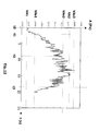
- the Fig. 12 illustrates a nonlimiting example of a variation of the area A determined in a gray level curve over time, that is to say on an SQ sequence of images I acquired.
- the value of area A corresponds to the absence of fog.
- the value VA1 equivalent to 1777 pixels is represented which corresponds to the area A1 in the reference gray level curve CL1 without fog F previously shown in FIG. Fig. 10 .
- the value of the area A changes as a function of the variations of the surrounding atmosphere around the vehicle and also of the atmosphere in front of the vehicle, and therefore according to the presence or no fog F in which is the vehicle or in which will enter the vehicle.
- the vehicle V is not yet in the fog, but detects that it is approaching the fog F.
- Fog detection F is therefore anticipated, thanks to the front camera.
- the first threshold value VAs1 is equal to 3000. Below this value, it is estimated that there is noise.
- the value of the area A is greater than a second threshold value VAs2 characteristic of the fog F.
- the vehicle V is thus in the fog layer F.
- this value VAs is around 7000 pixels and corresponds to a fog of medium density.
- the value VA2 equivalent to 8057 pixels for example corresponds to the area A2 in the grayscale curve CL2 with mist F shown previously in FIG. Fig. 11 is thus beyond this second threshold VAs2.
- a third threshold value VAs3 is used to define that the fog F in which the vehicle V is located is of high density. In a non-limiting exemplary embodiment, this third threshold value VAs3 is greater than 9000 pixels.
- the presence of fog F and its density is determined as a function of a visibility distance DVM, the latter being determined according to the previously determined area A (sub-step CALC_DVM (A) illustrated in FIG. the Fig. 5 ).
- this relation [1] does not depend on the type of bitumen, the quality of the road, or any other characteristic of the road, as explained above.
- the fog F when the visibility distance is less than 60 meters, it can be deduced that the fog F is of high density, whereas when it is greater than 60 meters and beyond, can infer that the fog F is average (60-100 meters) low density (100-150 meters).
- the calculation of the DVM sight distance thus makes it possible to subsequently supply the driver of the vehicle V with information on the maximum speed Vmax that must not be exceeded in order not to be in danger, and thus guarantee an optimum distance of safety.
- the stopping distance is about 80 meters.
- Second mode based on a CF guideline
- the analysis of the gray level curve is carried out as follows, as illustrated in FIG. Fig. 5 , 13 , 14 and 15 .
- a fifth substep 1e at least one tangent TG is calculated from a point of interest PT in said grayscale curve CL (sub-step CALC_TG (CL, PR) illustrated in FIG. Fig. 5 ).
- the point of interest PT is a characteristic point of a start of light scattering above the cut-off of a light beam FX emitted by vehicle PY projectors PJ in the presence of the fog F .
- the grayscale curve CL2 will vary significantly from this point of interest PT with respect to the reference curve CL1 without fog F.
- the point of interest PT is above the horizon line H of the acquired image 1. This makes it possible to be independent of the characteristics of the road (ground, wet road etc.) ) and in general of the road scene (tree, slope). Indeed, the upper part of the image I lying above this line H is less dependent on the road scene.
- the point of interest PT is the origin of the curve. Indeed, the point at the origin of the grayscale curve CL is above the horizon line H as shown in FIG. Fig. 14 .
- the advantage of this example is that there is no light scattering above the horizon line H, due to the illumination of the headlamps, in the absence of fog F, whereas exists in the presence of fog F as seen previously.
- the direction coefficient CF is determined from said tangent TG (sub-step CALC_CF (TG) illustrated in FIG. Fig. 5 ).
- the steering coefficient CF is characteristic of a change in the environment of the atmosphere around the vehicle V. Moreover, from this steering coefficient CF, it will be possible to calculate a DVM sight distance.
- the steering coefficient CF will make it possible to detect the presence of fog F and to deduce its density, either directly by means of threshold values, or via the visibility distance DVM as described below.
- a seventh substep 1g the presence of fog F and its density are determined.
- the presence of fog F and its density is determined as a function of several threshold values VS of said directing coefficient CF (sub-step CALC_F (VS) illustrated in FIG. Fig. 5 ).
- the presence of fog is determined according to a threshold value VS.
- this value is 0.15 for the non-limiting example taken from projectors in code position.
- this first threshold VS1 is equal to at 0.15.
- the fog F is not perceptible in the image 1.
- the density of the fog F is a function of a visibility distance DVM.
- the presence of fog F and its density is determined as a function of a visibility distance DVM, the latter being determined as a function of the steering coefficient CF (sub-step CALC_DVM (CF) illustrated in FIG. Fig. 5 ).
- this relationship [1] does not depend on the type of bitumen, the quality of the road, or any other characteristic of the road as described above.
- the point of interest PT determined is only translated in the acquired image 1 compared to the previous image without pitching, (upwards when the vehicle brakes, and downwards when the vehicle accelerates).
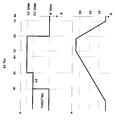
- the Fig. 15 illustrates a nonlimiting example of variations in the visibility distance DVM (in ordinate in meters) as a function of time (in abscissa in seconds).
- the first DVM_R curve is empirical visibility distance data that has been measured over time in actual tests.
- the second curve DVM_C concerns the distance of visibility DVM calculated according to relation [1] in the course of time.
- the second curve DVM_C is very close to the first curve DVM_R.
- the calculation of the visibility distance as a function of the steering coefficient CF according to the relation [1] is a reliable indicator which makes it possible to give reliable values of the distance of DVM visibility compared to the actual visibility distance.
- the fog F when the visibility distance is less than 60 meters, it can be deduced that the fog F is of high density, whereas when it is greater than 60 meters and beyond, can infer that the fog F is average (60-100 meters) low density (100-150 meters).
- calculating the visibility distance DVM can subsequently provide the driver of the vehicle V information on the maximum speed Vmax not to exceed not to be in danger, and thus ensure an optimum distance.
- the stopping distance is about 80 meters.
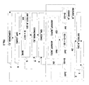
- a second step 2) the illumination range B of the light beam FX is increased relative to a maximum permitted range BM as a function of the detected backscatter.
- the maximum authorized range BM corresponds to the authorized regulation lighting for projectors in code position and is defined in the European regulation concerning the lighting for projectors Directive 97/28 / EC of the commission of June 11, 1997.
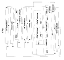
- the illumination range B of the light beam FX is increased with respect to a maximum permitted range BM of the projectors PJ so as to be able to measure the visibility distance D up to a first visibility threshold S1 if the visibility distance D is greater than a second visibility threshold S2.
- the second visibility threshold S2 is defined so as to ensure that the increase in the lighting range B is sufficient to make a visibility distance measurement D up to the first visibility threshold S1.
- the range corresponds to that of the regulated codes.
- the range must be regulated to optimize the backscatter can hinder the driver and also allow the measurement of the visibility distance.
- This first visibility threshold S1 is the automatic switching threshold of the code position, with increased range, in the road position, as will be seen later.
- this first visibility threshold S1 is equal to 70 meters.
- S2 equal to 40 meters.
- the first visibility threshold S1 is equal to 100 meters.
- S2 equal to 50 meters.
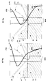
- the increase of the lighting range B is carried out in stages (step ADJUST_B (P1) on the Fig. 2 ).
- This first level P1 is defined so as to allow the measurement of the visibility distance to the first visibility threshold S1.
- the PJ projectors are always in code position but with an increased scope MOD_C2.
- the increase of the illumination range B of the light beam FX of the projectors PJ is carried out continuously, and in a non-limiting example as a function of the visibility distance D measured (step ADJUST_B (D) of the Fig. 2 ).
- the second visibility threshold S2 is equal to 50 meters.
- the lighting range B is gradually increased as the visibility distance D is below the first visibility threshold S1.
- the PJ projectors are always in code position but with an increased scope MOD_C2.
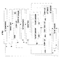
- the lighting range B of the light beam FX is increased with respect to a maximum permitted range BM of the projectors PJ so as to be able to measure the area A in said gray level curve if the area A reaches a second surface threshold value SA2.
- the second surface threshold SA2 is defined so as to ensure that the increase in the lighting range B is sufficient to make a measurement of the area A.
- the range corresponds to that of the regulated codes. As soon as the area A reaches the second threshold SA2, the range must be regulated to optimize the backscatter that can disturb the driver and also allow the measurement of the area A, as illustrated on the diagram. Fig. 19 . In the nonlimiting example, the area A decreased because the fog F has attenuated.
- the increase in the lighting range B of the PJ projectors is triggered, as illustrated in FIG. Fig. 19 .
- the increase of the lighting range as a function of the measured area A is carried out so as to be able to measure the area A up to a first surface threshold SA1 if the area measured before increasing the range of lighting reaches a second surface threshold SA2.
- This first surface threshold SA1 is the automatic switching threshold of the code position, with increased range, in the road position.
- FIG. Fig. 19 shows the evolution of the area A of the curve at each moment.
- this second surface threshold SA2 is equal to 3000
- the first surface threshold SA1 is equal to 4000
- the increase of the lighting range B is carried out in stages (step ADJUST_B (P1) on the Fig. 3 ).
- the increase of the illumination range B of the light beam FX of the projectors PJ is carried out continuously, and in a non-limiting example as a function of the measured area A (step ADJUST_B (A) of the Fig. 3 ).
- the lighting range B of the light beam FX is increased with respect to a maximum permitted range BM of the projectors PJ so as to be able to measure a directing coefficient CF of at least one tangent in said curve if the coefficient reaches a second threshold value of inclination SC2.
- the second inclination threshold value SC2 is defined so as to ensure that the increase in the illumination range B is sufficient to make a measurement of the steering coefficient CF.
- the range corresponds to that of the regulated codes. As soon as the steering coefficient CF reaches this second inclination threshold SC2, the range must be regulated in order to optimize the backscattering that can disturb the driver and also allow the measurement of the steering coefficient CF.
- the example of Fig. 19 of the second mode described above can be transposed to this third mode.
- the increase of the lighting range B of the projectors PJ is triggered.
- the increase in the lighting range as a function of the measured steer coefficient is effected so as to be able to measure the steer coefficient up to a first inclination threshold SC1 if the measured master coefficient before increasing the lighting range reaches a second threshold SC2.
- This first skew threshold SC1 is the automatic switching threshold of the code position, with increased range, in the road position.
- this second inclination threshold SC2 is equal to 0.3
- the first inclination threshold SC1 is equal to 0.5
- the third threshold is 0.95.
- the increase of the lighting range B is carried out in stages (step ADJUST_B (P1) on the Fig. 4 ).
- the increase of the illumination range B of the light beam FX of the projectors PJ is carried out continuously, and in a non-limiting example as a function of the measured direction coefficient CF (step ADJUST_B ( CF) of the Fig. 4 ).
- the illumination range B of the light beam FX of the projectors PJ is adjusted as a function of an obstacle O lying in the front environment of the motor vehicle considered V.
- the lighting range B is adjusted during the increase of the illumination range B of the light beam FX of the projectors so that the light beam FX comprises a cut-off line which is positioned in position. below a given axis of an obstacle in front of the motor vehicle.
- this axis represents the horizontal axis passing through the eyes of a driver of the motor vehicle situated in front of the motor vehicle in question, whether it is a crossover vehicle or a vehicle followed by the motor vehicle considered.
- a third step 3 the automatic switching of the projectors PJ from the first lighting mode MOD_C to the second lighting mode MOD_R is allowed when the backscattering reaches the first determined threshold T1. (step ON_COM1 illustrated on Fig. 1 to 4 ).
- This step is described below according to the three non-limiting embodiments described above in the first step (measurement of visibility distance, area, steering coefficient).
- the automatic switching of the PJ projectors from the code position mode to the road position mode is allowed when the visibility distance D reaches the first visibility threshold S1 and in particular when it becomes higher (step ON_COM1 illustrated on FIG. the Fig. 2 ) (and that the PJ projectors are in code position with increased range).
- the first visibility threshold S1 is equal to the first determined threshold T1.
- the visibility distance D is greater than the first visibility threshold S1
- the driver of the motor vehicle V will be hampered by a backscattering of the light beam FX of the PJ projectors on the fog, if the latter still exists. . It can therefore allow switching to the road position because the latter will not be more troublesome for the driver if it is performed.
- the first visibility threshold S1 is the automatic switching threshold of the code position with increased range in the road position. It is therefore the visibility distance threshold which ensures that the driver of the motor vehicle V will not be hampered by the backscattering of the fog in the road position.
- the visibility distance D reaches the first visibility threshold S1 and passes above.
- the fog has completely dissipated or almost.
- the switching mode of the headlights PJ of the motor vehicle is allowed to change from the code position MOD_C2 with increased range to the road position MOD_R (high beam or full headlight). It is the same for the example of the Fig. 18 at time t7.
- switching is authorized automatic PJ projectors from the code position mode to the road position mode when the measured area A reaches the first surface threshold value SA1 (step ON_COM1 illustrated on FIG. Fig. 3 ) (and that the PJ projectors are in code position with increased range), as shown in Fig. 19 .
- the first surface threshold SA1 is equal to the first determined threshold T1.
- the automatic switching of the PJ projectors from the code position mode to the road position mode is allowed when the measured steering coefficient CF reaches the first inclination threshold value SC1 (step ON_COM1 illustrated on FIG. Fig. 4 ) (and that the PJ projectors are in code position with increased range).
- the first inclination threshold SC1 is equal to the first determined threshold T1.
- Fig. 19 of the second mode described above can be transposed to this third mode.
- a fourth step 4 the PJ projectors are switched into a second lighting mode MOD_R, namely in the example taken, in the road position mode, when the backscattering reaches a first determined threshold T1.
- the first threshold T1 is determined so that the visibility in the second lighting mode MOD_R is greater than the visibility in the first lighting mode MOD_C.
- the road position is also triggered when the motor vehicle is in an unlit environment, for example in open country, and without there being a vehicle in front (crossed or followed).
- the measurement of the luminous environment can be determined either by the integration time of the camera which exceeds a certain threshold or by calculating the average value of the light intensity of the image which exceeds a certain threshold.
- This step is described below according to the three non-limiting embodiments described above in the first step (measurement of visibility distance, area, steering coefficient).
- the PJ projectors are switched in a second lighting mode MOD_R, namely in the example taken, in the road position mode, when the visibility distance D reaches the first visibility threshold S1 and especially when it becomes superior.
- the first visibility threshold S1 is equal to the first determined threshold T1.
- the projectors PJ are in the road position MOD_R and the visibility distance D becomes greater than the first visibility threshold S1.
- the PJ projectors are switched in a second lighting mode MOD_R, namely in the example taken, in the road position mode, when the measured area A reaches the first surface threshold SA1, as illustrated in Fig. 19 at time t6.
- the first surface threshold SA1 is equal to the first determined threshold T1.
- the PJ projectors are switched in a second lighting mode MOD_R, ie in the example taken, in the road position mode, when the measured steering coefficient reaches the first inclination threshold SC1.
- the first inclination threshold SC1 is equal to the first determined threshold T1.
- Fig. 19 of the second mode described above can be transposed to this third mode.
- a fifth step 5 the backscattering of the light beam FX of the projectors PJ is detected on a disturbance phenomenon of visibility (step DETECT_R of the Fig. 1 ) when the projectors are in the second mode MOD_R.
- a sixth step 6 it is forbidden to automatically switch the PJ projectors from the code position mode to the road position mode (step OFF_COM1 illustrated in FIGS. Fig. 1 to 4 ) when the detected backscattering reaches a third threshold T3.
- This step is described below according to the three non-limiting embodiments described above in the first step (measurement of visibility distance, area, steering coefficient).
- the fog causes inconvenience to the driver who may put him in danger. Under these conditions, it is therefore important that the code-route switching be inhibited.
- the PJ projectors would remain in the road position if no vehicle is in the front environment of the motor vehicle V putting the driver in a risky situation or else requiring him to deactivate himself the switching to bring about a disturbance of his conduct.
- this step is performed in parallel with the seventh following step. That is, the prohibition occurs at the same time as switching to the code position.
- this step occurs before the seventh step.
- a seventh step 7 the PJ projectors are switched in the first lighting mode MOD_C in order to reduce the backscattering of the light beam FX of the projectors PJ on the visibility disturbance phenomenon F when the detected backscattering reaches a third threshold T3.
- the first lighting mode MOD_C is the mode in code position.
- this prevents a driver of the motor vehicle V is hampered by the phenomenon of backscattering that results from the diffusion of the light beam FX of the projectors PJ on the disturbance phenomenon of visibility F.
- This third threshold T3 thus corresponds to the backscattering threshold above which the driver of the motor vehicle V considered is hindered by the backscattering of the headlamps in road position on the fog.
- the headlamps are automatically switched from the road position to the code position.
- the switching of the projectors from the road position mode to the code position mode is carried out without increasing the lighting range B with respect to the maximum permitted range BM.
- the switching of the projectors from the road position mode to the code position mode is carried out with increasing the lighting range B relative to the maximum authorized range BM.
- This step is described below according to the three non-limiting embodiments described above in the first step (measurement of visibility distance, area, steering coefficient).
- the PJ projectors are switched in the first lighting mode MOD_C in order to reduce the backscattering of the light beam FX of the headlamps PJ on the visibility-impairing phenomenon F when the visibility distance D reaches one third visibility threshold S3 and in particular when it falls below this third threshold S3.
- the third visibility threshold S3 thus corresponds here to the third threshold T3.
- This third visibility threshold S3 thus corresponds to the threshold of visibility distance below which the driver of the motor vehicle V considered is hindered by the backscattering of the headlamps in road position on the fog.
- Examples of Fig. 16 and 17 show switching without increasing range at time t2, while the example of Fig. 18 shows a switching with increasing range at time t2.
- the second visibility threshold S2 is greater than the third visibility threshold S3, while in the second embodiment, in the third example of the Fig. 18 the second visibility threshold S2 is lower than the third visibility threshold S3.
- the advantage of the first variant of embodiment is to take into account the phenomenon disturbing visibility F, and therefore backscattering, as soon as it becomes troublesome for the driver of the motor vehicle V, so as to adjust the projectors PJ for that it is no longer inconvenient for the driver.
- the lighting range B of the beam of light FX projectors is equal to the maximum permitted range BM. There is no increase in scope.
- the second visibility threshold S2 will be greater than the third visibility threshold S3, and equal to 50 meters.
- the third visibility threshold S3 is set at 40 meters
- the second visibility threshold S2 was lower than the third visibility threshold S3 as in the second embodiment, there would be switching to code position with increased range, which would be inconvenient for the driver, because at the visibility threshold S3 equal to 40 meters, the backscattering of the increased light beam is too strong.
- the advantage of the second embodiment is to always be able to detect backscattering in code position mode.
- the lighting range B of the light beam FX of the projectors is increased relative to the maximum authorized range BM so as to illuminate up to at the first visibility threshold S1, then decreased as the visibility distance decreases.
- the second visibility threshold S2 will be lower than the third visibility threshold S3, and equal to 50 meters.
- the third threshold of visibility S3 is set at 80 meters
- the second visibility threshold S2 was greater than the third visibility threshold S3 as in the first embodiment, there would be switching to code position without increasing the range, which would be inconvenient to detect the backscattering thereafter, because at the visibility threshold S3 equal to 80 meters, the backscattering of the light beam is very low.
- the PJ projectors are switched in the first lighting mode MOD_C in order to reduce the backscattering of the light beam FX of the projectors PJ on the disturbance phenomenon of visibility F when the measured area A reaches a maximum third SA3 surface threshold, as illustrated on the Fig. 19 at time t2.
- the third surface threshold SA3 therefore corresponds here to the third threshold T3.
- This third surface threshold SA3 thus corresponds to the threshold of the measured area A above which the driver of the motor vehicle V considered is hindered by the backscattering of the headlamps in road position on the fog.
- the PJ projectors are switched in the first lighting mode MOD_C in order to reduce the backscattering of the light beam FX of the projectors PJ on the visibility-impairing phenomenon F when the measured control coefficient CF reaches a maximum third inclination threshold SC3.
- the third inclination threshold SC3 thus corresponds here to the third threshold T3.
- This third skew threshold SC3 thus corresponds to the threshold of the measured measured coefficient CF above which the driver of the motor vehicle V considered is hindered by the backscattering of the headlamps in road position on the fog.
- Fig. 19 of the second mode described above can be transposed to this third mode.
- the illumination range B of the light beam FX of the headlamps is adjusted according to the obstacles O situated in a front environment of the motor vehicle V. This makes it possible to avoid dazzling vehicles. crossed or followed by the vehicle considered V as seen previously. Thus, if we are in a code position mode with increased range, the increased range will be decreased if there is an obstacle O such as a crossed and followed vehicle and according to the distance to which it is located.
- the steps 1 to 7 described above are executed in real time, as and when the visibility distance D which is due to the presence or not and to the variations of a disturbance phenomenon of visibility F is modified. .
- the described method makes it possible to switch the headlights of a motor vehicle from one lighting mode to another depending on the disturbing phenomenon that occurs or disappears and its variations.
- the method of the invention is implemented by a device DISP for automatically switching projectors capable of emitting a light beam FX for a motor vehicle V from one lighting mode to another lighting mode, represented in FIG. Fig. 20 .
- This device DISP is integrated in the motor vehicle V.
- control unit UC furthermore makes it possible to switch the projectors PJ in the first lighting mode MOD_C in order to reduce a backscattering of the light beam FX of the projectors (PJ) on a a disturbance phenomenon of visibility F when the detected backscattering reaches a third threshold T3.
- the increase unit UA of the range of the lighting of the headlamps comprises a CORR trimmer of the motor vehicle and the increase of the lighting range B in the code position. is performed using a correction function in situ to raise the beam when the motor vehicle has a neutral attitude.
- a CORR attitude corrector generally uses a correction function in site to ensure a constant lighting range regardless of the attitude variations of the motor vehicle. This function is reflected by raising the beam in braking situations and lowering the beam in acceleration situations in order to avoid dazzling crossed or tracked vehicles.
- This first mode makes it possible to use a device (the attitude corrector) which is already implanted in many vehicles.
- the increase unit UA of the range of the lighting of the projectors comprises an optical module MO composed in particular of a mobile cover CH and a mechanical actuator AC for actuating the mobile cover CH, the mobile cache being adapted to intercepter including a portion of the light beam FX emitted by the projectors PJ.
- the increase of the lighting range B in code position is thus done by using a function of interception of a part of the light beam FX projectors.
- this function is based on the use of an optical module MO, well known to those skilled in the art, called a bi-function module able to operate in code position mode (active position of the CH cache creating a regulated cut beam ) and in road position mode (retracted position of the cover CH) in which a plurality of intermediate positions of the moving cover CH add to the known positions so as to more or less intercept the emitted light beam FX and thus to emit a light beam FX with different cut lines.
- code position mode active position of the CH cache creating a regulated cut beam
- road position mode retract position of the cover CH
- This second embodiment makes it possible to have flexibility in the range of the light beam FX of the projectors that one wishes to obtain.
- the mobile cover CH can take different intermediate positions that allow to obtain a very large number of different ranges of the light beam FX which thus has a different cut line.
- the cache CH can be mobile according to different variants which adds other possibilities of intermediate positions and therefore cut lines and therefore different ranges.
- it can be movable in a direction substantially perpendicular to the optical axis of the projectors (y-y) or in an elliptical direction.
- the optical module MO is integrated in each of the projectors of the motor vehicle V as shown in FIG. Fig. 20 with dots.
- control unit UC also makes it possible to control the mechanical actuator AC.
- control is effected according to the measured visibility distance D, the area A or the steering coefficient CF.
- control is performed so as to have a non-dazzling FX light beam in the case where an obstacle is in front of the motor vehicle V as described. previously.
- these two embodiments of the augmentation unit UA make it possible to modify the cutoff line of the light beam FX of the projectors to raise the beam relative to the maximum authorized range BM by the European lighting regulations.
- the regulated cutoff line of a light beam FX of a projector in code position is oriented with a slope between -1% radian and -1.5% radian.
- the FX light beam illuminates the ground for a distance of approximately 60 meters ahead of the motor vehicle.
- the switching device DISP may comprise a computer program product PG comprising one or more instruction sequences executable by an information processing unit such as a microprocessor, or a processing unit of a microcontroller , an ASIC, a computer, etc., the execution of said instruction sequences allowing implementation of the method described.
- an information processing unit such as a microprocessor, or a processing unit of a microcontroller , an ASIC, a computer, etc.
- Such a PG computer program can be written in non-volatile memory writable type ROM or non-volatile memory rewritable type EEPROM or FLASH. Said PG computer program can be registered in the factory or loaded into memory or downloaded remotely in memory.
- the instruction sequences can be sequences of machine instructions, or sequences of a control language interpreted by the processing unit at the time of their execution.
- the computer program PG is written in a memory of the control unit UC of the device DISP.
- the description of the method is not limited to the embodiments and examples described above.
- the method can be applied to a disturbing phenomenon F which in addition to the fog, can be heavy rain or snow in non-limiting examples.
Landscapes
- Engineering & Computer Science (AREA)
- Mechanical Engineering (AREA)
- Lighting Device Outwards From Vehicle And Optical Signal (AREA)
Applications Claiming Priority (1)
| Application Number | Priority Date | Filing Date | Title |
|---|---|---|---|
| FR0807302A FR2940205B1 (fr) | 2008-12-19 | 2008-12-19 | Procede de commutation du mode d'eclairage de projecteurs pour vehicule automobile. |
Publications (2)
| Publication Number | Publication Date |
|---|---|
| EP2199152A1 true EP2199152A1 (de) | 2010-06-23 |
| EP2199152B1 EP2199152B1 (de) | 2015-09-16 |
Family
ID=40912045
Family Applications (1)
| Application Number | Title | Priority Date | Filing Date |
|---|---|---|---|
| EP09179275.4A Active EP2199152B1 (de) | 2008-12-19 | 2009-12-15 | Umschaltverfahren des Beleuchtungsmodus von Kraftfahrzeugscheinwerfern |
Country Status (4)
| Country | Link |
|---|---|
| US (1) | US8465184B2 (de) |
| EP (1) | EP2199152B1 (de) |
| JP (1) | JP5570800B2 (de) |
| FR (1) | FR2940205B1 (de) |
Cited By (4)
| Publication number | Priority date | Publication date | Assignee | Title |
|---|---|---|---|---|
| EP3095641A1 (de) * | 2015-05-20 | 2016-11-23 | Goodrich Lighting Systems GmbH | Flugzeuglandescheinwerfer, flugzeugaussenbeleuchtungssystem und verfahren zum betrieb eines flugzeuglandescheinwerfers |
| EP3269596A1 (de) * | 2016-07-16 | 2018-01-17 | Goodrich Lighting Systems GmbH | Hubschraubersuchscheinwerfer |
| WO2019115313A1 (en) * | 2017-12-14 | 2019-06-20 | Lumileds Holding B.V. | Illuminant for vehicle headlight with automatic beam mode selection |
| US20200241136A1 (en) * | 2019-01-28 | 2020-07-30 | Stanley Electric Co., Ltd. | Apparatuses and methods for backscattering elimination via spatial and temporal modulations |
Families Citing this family (6)
| Publication number | Priority date | Publication date | Assignee | Title |
|---|---|---|---|---|
| DE102009002101A1 (de) * | 2009-04-01 | 2010-10-14 | Robert Bosch Gmbh | Verfahren und Vorrichtung zur Ausleuchtung von Fahrbahnseitenbereichen |
| WO2012066999A1 (ja) * | 2010-11-16 | 2012-05-24 | 本田技研工業株式会社 | 車載カメラの変位量検出装置 |
| DE102011017644A1 (de) | 2011-04-28 | 2012-10-31 | Robert Bosch Gmbh | Verfahren zur Steuerung einer Scheinwerferanlage eines Fahrzeugs und Vorrichtung zur Ansteuerung einer Scheinwerferanlage eines Fahrzeugs |
| DE102011017649B3 (de) * | 2011-04-28 | 2012-10-11 | Robert Bosch Gmbh | Verfahren und Vorrichtung zur Erkennung einer Intensität eines Aerosols in einem Sichtfeld einer Kamera eines Fahrzeugs |
| WO2014133868A1 (en) | 2013-03-01 | 2014-09-04 | Gentex Corporation | Vehicle imaging system and method for categorizing objects using relative motion analysis |
| KR101426801B1 (ko) | 2013-03-14 | 2014-08-05 | 주식회사 만도 | 운전자 편의 장치 및 그의 제어 방법 |
Citations (4)
| Publication number | Priority date | Publication date | Assignee | Title |
|---|---|---|---|---|
| EP0516527A1 (de) * | 1991-05-29 | 1992-12-02 | Valeo Vision | Beleuchtungs- und/oder Anzeige-Vorrichtung für Nebelwetter |
| US20040201483A1 (en) * | 2003-02-21 | 2004-10-14 | Stam Joseph S. | Automatic vehicle exterior light control systems |
| DE102005061094A1 (de) * | 2005-03-19 | 2006-09-28 | Hella Kgaa Hueck & Co. | Scheinwerfer für Fahrzeuge |
| US20070242470A1 (en) * | 2006-04-10 | 2007-10-18 | Denso Corporation | Lighting control system for control dependent on weather condition |
Family Cites Families (8)
| Publication number | Priority date | Publication date | Assignee | Title |
|---|---|---|---|---|
| JP2861737B2 (ja) * | 1993-08-05 | 1999-02-24 | トヨタ自動車株式会社 | 車両用前照灯 |
| JP3861342B2 (ja) * | 1996-10-23 | 2006-12-20 | トヨタ自動車株式会社 | ヘッドランプの配光制御装置 |
| JPH1128971A (ja) * | 1997-07-11 | 1999-02-02 | Nissan Motor Co Ltd | 車両用前照灯装置 |
| JPH11321440A (ja) * | 1998-05-18 | 1999-11-24 | Koito Mfg Co Ltd | 車輌用灯具装置 |
| JP2001351411A (ja) * | 2000-06-01 | 2001-12-21 | Ichikoh Ind Ltd | 自動車用フォグランプ |
| US6969183B2 (en) * | 2002-12-27 | 2005-11-29 | Ichikoh Industries, Ltd. | Digital lighting apparatus for vehicle, controller for digital lighting apparatus, and control program for digital lighting apparatus |
| FR2884637B1 (fr) * | 2005-04-19 | 2007-06-29 | Valeo Vision Sa | Procede de detection de brouillard nocturne et systeme de mise en oeuvre de ce procede |
| FR2902556B1 (fr) * | 2006-06-15 | 2008-08-15 | Valeo Vision Sa | Procede de determination d'une distance de visibilite pour un conducteur d'un vehicule. |
-
2008
- 2008-12-19 FR FR0807302A patent/FR2940205B1/fr active Active
-
2009
- 2009-12-15 EP EP09179275.4A patent/EP2199152B1/de active Active
- 2009-12-17 US US12/640,250 patent/US8465184B2/en active Active
- 2009-12-18 JP JP2009287786A patent/JP5570800B2/ja active Active
Patent Citations (4)
| Publication number | Priority date | Publication date | Assignee | Title |
|---|---|---|---|---|
| EP0516527A1 (de) * | 1991-05-29 | 1992-12-02 | Valeo Vision | Beleuchtungs- und/oder Anzeige-Vorrichtung für Nebelwetter |
| US20040201483A1 (en) * | 2003-02-21 | 2004-10-14 | Stam Joseph S. | Automatic vehicle exterior light control systems |
| DE102005061094A1 (de) * | 2005-03-19 | 2006-09-28 | Hella Kgaa Hueck & Co. | Scheinwerfer für Fahrzeuge |
| US20070242470A1 (en) * | 2006-04-10 | 2007-10-18 | Denso Corporation | Lighting control system for control dependent on weather condition |
Cited By (7)
| Publication number | Priority date | Publication date | Assignee | Title |
|---|---|---|---|---|
| EP3095641A1 (de) * | 2015-05-20 | 2016-11-23 | Goodrich Lighting Systems GmbH | Flugzeuglandescheinwerfer, flugzeugaussenbeleuchtungssystem und verfahren zum betrieb eines flugzeuglandescheinwerfers |
| US9723677B2 (en) | 2015-05-20 | 2017-08-01 | Goodrich Lighting Systems Gmbh | Aircraft landing light unit, exterior aircraft lighting system and method of operating an aircraft landing light unit |
| EP3269596A1 (de) * | 2016-07-16 | 2018-01-17 | Goodrich Lighting Systems GmbH | Hubschraubersuchscheinwerfer |
| US10136492B2 (en) | 2016-07-16 | 2018-11-20 | Goodrich Lighting Systems Gmbh | Helicopter search light |
| WO2019115313A1 (en) * | 2017-12-14 | 2019-06-20 | Lumileds Holding B.V. | Illuminant for vehicle headlight with automatic beam mode selection |
| US20200241136A1 (en) * | 2019-01-28 | 2020-07-30 | Stanley Electric Co., Ltd. | Apparatuses and methods for backscattering elimination via spatial and temporal modulations |
| US11604345B2 (en) * | 2019-01-28 | 2023-03-14 | Stanley Electric Co., Ltd. | Apparatuses and methods for backscattering elimination via spatial and temporal modulations |
Also Published As
| Publication number | Publication date |
|---|---|
| JP5570800B2 (ja) | 2014-08-13 |
| US8465184B2 (en) | 2013-06-18 |
| US20100157614A1 (en) | 2010-06-24 |
| FR2940205B1 (fr) | 2011-11-25 |
| FR2940205A1 (fr) | 2010-06-25 |
| JP2010143573A (ja) | 2010-07-01 |
| EP2199152B1 (de) | 2015-09-16 |
Similar Documents
| Publication | Publication Date | Title |
|---|---|---|
| EP2199152B1 (de) | Umschaltverfahren des Beleuchtungsmodus von Kraftfahrzeugscheinwerfern | |
| EP2056093B1 (de) | Verfahren zur Erkennung eines die Sichtweite eines Fahrzeuges störenden Phänomens | |
| EP2061006B1 (de) | Erfassungsverfahren eines Störphänomens der Sicht für ein Fahrzeug | |
| EP2020595B1 (de) | Erfassungsverfahren eines Fahrzeugs für ein Störphänomen der Sicht | |
| EP2892758B1 (de) | Verfahren zur steuerung eines adaptiven beleuchtungssystems | |
| EP2479064B1 (de) | Verfahren und Vorrichtung zur Kontrolle eines Lichtbündels, das von einem Fahrzeug, insbesondere einem Auto, ausgesandt wird | |
| EP2743129B1 (de) | Verfahren und Vorrichtung zur Steuerung eines Lichtstrahls | |
| EP3422706B1 (de) | Leuchtsystem für kraftfahrzeug | |
| WO2012042171A2 (fr) | Procede et dispositif de detection de brouillard, la nuit | |
| EP2988972B1 (de) | Verfahren zur steuerung eines regulierbaren beleuchtungssystems für ein trägerfahrzeug und reguliebares beleuchtungsystem | |
| EP3059121B1 (de) | Erzeugung und fernverarbeitung von photometriedaten | |
| EP2165882B1 (de) | Regulierungsverfahren der Leuchtstärke von Kraftfahrzeugscheinwerfern | |
| FR2988052A1 (fr) | Procede d'adaptation d'au moins un parametre photometrique d'une source lumineuse de vehicule automobile et systeme d'adaptation correspondant | |
| EP4251473A1 (de) | Verfahren zur steuerung eines beleuchtungssystems mit einer blendfreien beleuchtungsfunktion | |
| EP1987985A1 (de) | Verfahren zur Richtungssteuerung von Fahrzeugscheinwerfern | |
| FR3105143A1 (fr) | Procédé de détection d’un état local de la route sur laquelle circule un véhicule automobile | |
| EP2807054B1 (de) | Fahrzeugfrontbeleuchtung | |
| EP2165881A1 (de) | Regulierungsverfahren der Leuchtstärke von Fahrzeugscheinwerfern | |
| FR3159695A1 (fr) | Procédé pour l’estimation de distance, élément informatique, programme d’ordinateur et système embarqué pour la mise en œuvre du procédé | |
| FR3055267A1 (fr) | Dispositif de commande d'un projecteur de lumiere d'un vehicule, dispositif d'eclairage et procede associes | |
| WO2006048559A1 (fr) | Systeme de feux de croisement pour vehicules automobiles | |
| FR3005139A1 (fr) | Procede de commande d'un systeme d'eclairage reglable, pour un vehicule porteur |
Legal Events
| Date | Code | Title | Description |
|---|---|---|---|
| PUAI | Public reference made under article 153(3) epc to a published international application that has entered the european phase |
Free format text: ORIGINAL CODE: 0009012 |
|
| AK | Designated contracting states |
Kind code of ref document: A1 Designated state(s): AT BE BG CH CY CZ DE DK EE ES FI FR GB GR HR HU IE IS IT LI LT LU LV MC MK MT NL NO PL PT RO SE SI SK SM TR |
|
| AX | Request for extension of the european patent |
Extension state: AL BA RS |
|
| 17P | Request for examination filed |
Effective date: 20101211 |
|
| 17Q | First examination report despatched |
Effective date: 20110118 |
|
| R17P | Request for examination filed (corrected) |
Effective date: 20101209 |
|
| GRAP | Despatch of communication of intention to grant a patent |
Free format text: ORIGINAL CODE: EPIDOSNIGR1 |
|
| INTG | Intention to grant announced |
Effective date: 20150427 |
|
| GRAS | Grant fee paid |
Free format text: ORIGINAL CODE: EPIDOSNIGR3 |
|
| GRAA | (expected) grant |
Free format text: ORIGINAL CODE: 0009210 |
|
| AK | Designated contracting states |
Kind code of ref document: B1 Designated state(s): AT BE BG CH CY CZ DE DK EE ES FI FR GB GR HR HU IE IS IT LI LT LU LV MC MK MT NL NO PL PT RO SE SI SK SM TR |
|
| REG | Reference to a national code |
Ref country code: GB Ref legal event code: FG4D Free format text: NOT ENGLISH |
|
| REG | Reference to a national code |
Ref country code: CH Ref legal event code: EP |
|
| REG | Reference to a national code |
Ref country code: IE Ref legal event code: FG4D Free format text: LANGUAGE OF EP DOCUMENT: FRENCH |
|
| REG | Reference to a national code |
Ref country code: AT Ref legal event code: REF Ref document number: 749536 Country of ref document: AT Kind code of ref document: T Effective date: 20151015 |
|
| REG | Reference to a national code |
Ref country code: DE Ref legal event code: R096 Ref document number: 602009033643 Country of ref document: DE |
|
| REG | Reference to a national code |
Ref country code: NL Ref legal event code: MP Effective date: 20150916 |
|
| PG25 | Lapsed in a contracting state [announced via postgrant information from national office to epo] |
Ref country code: GR Free format text: LAPSE BECAUSE OF FAILURE TO SUBMIT A TRANSLATION OF THE DESCRIPTION OR TO PAY THE FEE WITHIN THE PRESCRIBED TIME-LIMIT Effective date: 20151217 Ref country code: NO Free format text: LAPSE BECAUSE OF FAILURE TO SUBMIT A TRANSLATION OF THE DESCRIPTION OR TO PAY THE FEE WITHIN THE PRESCRIBED TIME-LIMIT Effective date: 20151216 Ref country code: FI Free format text: LAPSE BECAUSE OF FAILURE TO SUBMIT A TRANSLATION OF THE DESCRIPTION OR TO PAY THE FEE WITHIN THE PRESCRIBED TIME-LIMIT Effective date: 20150916 Ref country code: LV Free format text: LAPSE BECAUSE OF FAILURE TO SUBMIT A TRANSLATION OF THE DESCRIPTION OR TO PAY THE FEE WITHIN THE PRESCRIBED TIME-LIMIT Effective date: 20150916 Ref country code: LT Free format text: LAPSE BECAUSE OF FAILURE TO SUBMIT A TRANSLATION OF THE DESCRIPTION OR TO PAY THE FEE WITHIN THE PRESCRIBED TIME-LIMIT Effective date: 20150916 |
|
| REG | Reference to a national code |
Ref country code: LT Ref legal event code: MG4D |
|
| REG | Reference to a national code |
Ref country code: AT Ref legal event code: MK05 Ref document number: 749536 Country of ref document: AT Kind code of ref document: T Effective date: 20150916 |
|
| PG25 | Lapsed in a contracting state [announced via postgrant information from national office to epo] |
Ref country code: HR Free format text: LAPSE BECAUSE OF FAILURE TO SUBMIT A TRANSLATION OF THE DESCRIPTION OR TO PAY THE FEE WITHIN THE PRESCRIBED TIME-LIMIT Effective date: 20150916 Ref country code: SE Free format text: LAPSE BECAUSE OF FAILURE TO SUBMIT A TRANSLATION OF THE DESCRIPTION OR TO PAY THE FEE WITHIN THE PRESCRIBED TIME-LIMIT Effective date: 20150916 |
|
| PG25 | Lapsed in a contracting state [announced via postgrant information from national office to epo] |
Ref country code: NL Free format text: LAPSE BECAUSE OF FAILURE TO SUBMIT A TRANSLATION OF THE DESCRIPTION OR TO PAY THE FEE WITHIN THE PRESCRIBED TIME-LIMIT Effective date: 20150916 |
|
| PG25 | Lapsed in a contracting state [announced via postgrant information from national office to epo] |
Ref country code: CZ Free format text: LAPSE BECAUSE OF FAILURE TO SUBMIT A TRANSLATION OF THE DESCRIPTION OR TO PAY THE FEE WITHIN THE PRESCRIBED TIME-LIMIT Effective date: 20150916 Ref country code: IT Free format text: LAPSE BECAUSE OF FAILURE TO SUBMIT A TRANSLATION OF THE DESCRIPTION OR TO PAY THE FEE WITHIN THE PRESCRIBED TIME-LIMIT Effective date: 20150916 Ref country code: SK Free format text: LAPSE BECAUSE OF FAILURE TO SUBMIT A TRANSLATION OF THE DESCRIPTION OR TO PAY THE FEE WITHIN THE PRESCRIBED TIME-LIMIT Effective date: 20150916 Ref country code: EE Free format text: LAPSE BECAUSE OF FAILURE TO SUBMIT A TRANSLATION OF THE DESCRIPTION OR TO PAY THE FEE WITHIN THE PRESCRIBED TIME-LIMIT Effective date: 20150916 Ref country code: IS Free format text: LAPSE BECAUSE OF FAILURE TO SUBMIT A TRANSLATION OF THE DESCRIPTION OR TO PAY THE FEE WITHIN THE PRESCRIBED TIME-LIMIT Effective date: 20160116 Ref country code: ES Free format text: LAPSE BECAUSE OF FAILURE TO SUBMIT A TRANSLATION OF THE DESCRIPTION OR TO PAY THE FEE WITHIN THE PRESCRIBED TIME-LIMIT Effective date: 20150916 |
|
| PG25 | Lapsed in a contracting state [announced via postgrant information from national office to epo] |
Ref country code: BE Free format text: LAPSE BECAUSE OF NON-PAYMENT OF DUE FEES Effective date: 20151231 Ref country code: PT Free format text: LAPSE BECAUSE OF FAILURE TO SUBMIT A TRANSLATION OF THE DESCRIPTION OR TO PAY THE FEE WITHIN THE PRESCRIBED TIME-LIMIT Effective date: 20160118 Ref country code: RO Free format text: LAPSE BECAUSE OF FAILURE TO SUBMIT A TRANSLATION OF THE DESCRIPTION OR TO PAY THE FEE WITHIN THE PRESCRIBED TIME-LIMIT Effective date: 20150916 Ref country code: PL Free format text: LAPSE BECAUSE OF FAILURE TO SUBMIT A TRANSLATION OF THE DESCRIPTION OR TO PAY THE FEE WITHIN THE PRESCRIBED TIME-LIMIT Effective date: 20150916 Ref country code: AT Free format text: LAPSE BECAUSE OF FAILURE TO SUBMIT A TRANSLATION OF THE DESCRIPTION OR TO PAY THE FEE WITHIN THE PRESCRIBED TIME-LIMIT Effective date: 20150916 |
|
| REG | Reference to a national code |
Ref country code: DE Ref legal event code: R097 Ref document number: 602009033643 Country of ref document: DE |
|
| PLBE | No opposition filed within time limit |
Free format text: ORIGINAL CODE: 0009261 |
|
| STAA | Information on the status of an ep patent application or granted ep patent |
Free format text: STATUS: NO OPPOSITION FILED WITHIN TIME LIMIT |
|
| PG25 | Lapsed in a contracting state [announced via postgrant information from national office to epo] |
Ref country code: MC Free format text: LAPSE BECAUSE OF FAILURE TO SUBMIT A TRANSLATION OF THE DESCRIPTION OR TO PAY THE FEE WITHIN THE PRESCRIBED TIME-LIMIT Effective date: 20150916 Ref country code: LU Free format text: LAPSE BECAUSE OF FAILURE TO SUBMIT A TRANSLATION OF THE DESCRIPTION OR TO PAY THE FEE WITHIN THE PRESCRIBED TIME-LIMIT Effective date: 20151215 |
|
| REG | Reference to a national code |
Ref country code: CH Ref legal event code: PL |
|
| 26N | No opposition filed |
Effective date: 20160617 |
|
| PG25 | Lapsed in a contracting state [announced via postgrant information from national office to epo] |
Ref country code: DK Free format text: LAPSE BECAUSE OF FAILURE TO SUBMIT A TRANSLATION OF THE DESCRIPTION OR TO PAY THE FEE WITHIN THE PRESCRIBED TIME-LIMIT Effective date: 20150916 |
|
| REG | Reference to a national code |
Ref country code: IE Ref legal event code: MM4A |
|
| REG | Reference to a national code |
Ref country code: FR Ref legal event code: ST Effective date: 20160831 |
|
| PG25 | Lapsed in a contracting state [announced via postgrant information from national office to epo] |
Ref country code: LI Free format text: LAPSE BECAUSE OF NON-PAYMENT OF DUE FEES Effective date: 20151231 Ref country code: IE Free format text: LAPSE BECAUSE OF NON-PAYMENT OF DUE FEES Effective date: 20151215 Ref country code: CH Free format text: LAPSE BECAUSE OF NON-PAYMENT OF DUE FEES Effective date: 20151231 |
|
| PG25 | Lapsed in a contracting state [announced via postgrant information from national office to epo] |
Ref country code: FR Free format text: LAPSE BECAUSE OF NON-PAYMENT OF DUE FEES Effective date: 20151231 Ref country code: SI Free format text: LAPSE BECAUSE OF FAILURE TO SUBMIT A TRANSLATION OF THE DESCRIPTION OR TO PAY THE FEE WITHIN THE PRESCRIBED TIME-LIMIT Effective date: 20150916 |
|
| PG25 | Lapsed in a contracting state [announced via postgrant information from national office to epo] |
Ref country code: BG Free format text: LAPSE BECAUSE OF FAILURE TO SUBMIT A TRANSLATION OF THE DESCRIPTION OR TO PAY THE FEE WITHIN THE PRESCRIBED TIME-LIMIT Effective date: 20150916 Ref country code: HU Free format text: LAPSE BECAUSE OF FAILURE TO SUBMIT A TRANSLATION OF THE DESCRIPTION OR TO PAY THE FEE WITHIN THE PRESCRIBED TIME-LIMIT; INVALID AB INITIO Effective date: 20091215 Ref country code: SM Free format text: LAPSE BECAUSE OF FAILURE TO SUBMIT A TRANSLATION OF THE DESCRIPTION OR TO PAY THE FEE WITHIN THE PRESCRIBED TIME-LIMIT Effective date: 20150916 |
|
| PG25 | Lapsed in a contracting state [announced via postgrant information from national office to epo] |
Ref country code: CY Free format text: LAPSE BECAUSE OF FAILURE TO SUBMIT A TRANSLATION OF THE DESCRIPTION OR TO PAY THE FEE WITHIN THE PRESCRIBED TIME-LIMIT Effective date: 20150916 |
|
| PG25 | Lapsed in a contracting state [announced via postgrant information from national office to epo] |
Ref country code: MT Free format text: LAPSE BECAUSE OF FAILURE TO SUBMIT A TRANSLATION OF THE DESCRIPTION OR TO PAY THE FEE WITHIN THE PRESCRIBED TIME-LIMIT Effective date: 20150916 Ref country code: TR Free format text: LAPSE BECAUSE OF FAILURE TO SUBMIT A TRANSLATION OF THE DESCRIPTION OR TO PAY THE FEE WITHIN THE PRESCRIBED TIME-LIMIT Effective date: 20150916 |
|
| PG25 | Lapsed in a contracting state [announced via postgrant information from national office to epo] |
Ref country code: MK Free format text: LAPSE BECAUSE OF FAILURE TO SUBMIT A TRANSLATION OF THE DESCRIPTION OR TO PAY THE FEE WITHIN THE PRESCRIBED TIME-LIMIT Effective date: 20150916 |
|
| P01 | Opt-out of the competence of the unified patent court (upc) registered |
Effective date: 20230528 |
|
| PGFP | Annual fee paid to national office [announced via postgrant information from national office to epo] |
Ref country code: GB Payment date: 20251229 Year of fee payment: 17 |
|
| PGFP | Annual fee paid to national office [announced via postgrant information from national office to epo] |
Ref country code: DE Payment date: 20251231 Year of fee payment: 17 |