EP2199063B1 - Beheiztes Flächenelement und Verfahren zu seiner Befestigung - Google Patents
Beheiztes Flächenelement und Verfahren zu seiner Befestigung Download PDFInfo
- Publication number
- EP2199063B1 EP2199063B1 EP09178098.1A EP09178098A EP2199063B1 EP 2199063 B1 EP2199063 B1 EP 2199063B1 EP 09178098 A EP09178098 A EP 09178098A EP 2199063 B1 EP2199063 B1 EP 2199063B1
- Authority
- EP
- European Patent Office
- Prior art keywords
- adhesive
- contacting
- self
- layer
- surface element
- Prior art date
- Legal status (The legal status is an assumption and is not a legal conclusion. Google has not performed a legal analysis and makes no representation as to the accuracy of the status listed.)
- Active
Links
- 238000000034 method Methods 0.000 title claims description 52
- 239000000853 adhesive Substances 0.000 claims description 275
- 238000010438 heat treatment Methods 0.000 claims description 125
- 239000000758 substrate Substances 0.000 claims description 119
- 239000000945 filler Substances 0.000 claims description 22
- OKTJSMMVPCPJKN-UHFFFAOYSA-N Carbon Chemical compound [C] OKTJSMMVPCPJKN-UHFFFAOYSA-N 0.000 claims description 15
- 239000004020 conductor Substances 0.000 claims description 13
- 239000006229 carbon black Substances 0.000 claims description 7
- 229910002804 graphite Inorganic materials 0.000 claims description 5
- 239000010439 graphite Substances 0.000 claims description 5
- 239000011852 carbon nanoparticle Substances 0.000 claims description 3
- 238000005304 joining Methods 0.000 claims description 3
- VNWKTOKETHGBQD-UHFFFAOYSA-N methane Chemical compound C VNWKTOKETHGBQD-UHFFFAOYSA-N 0.000 claims description 2
- 239000010410 layer Substances 0.000 description 172
- 230000001070 adhesive effect Effects 0.000 description 116
- 239000000203 mixture Substances 0.000 description 73
- 239000004820 Pressure-sensitive adhesive Substances 0.000 description 37
- 239000004831 Hot glue Substances 0.000 description 31
- 230000000694 effects Effects 0.000 description 27
- 229920000642 polymer Polymers 0.000 description 25
- 239000011231 conductive filler Substances 0.000 description 21
- 230000008569 process Effects 0.000 description 21
- 239000002131 composite material Substances 0.000 description 20
- 239000000178 monomer Substances 0.000 description 20
- 238000003860 storage Methods 0.000 description 19
- 239000000463 material Substances 0.000 description 18
- 238000004132 cross linking Methods 0.000 description 16
- -1 polyethylene Polymers 0.000 description 16
- 229910052751 metal Inorganic materials 0.000 description 13
- 239000002184 metal Substances 0.000 description 13
- 239000013615 primer Substances 0.000 description 13
- 239000002987 primer (paints) Substances 0.000 description 13
- 229920005989 resin Polymers 0.000 description 13
- 239000011347 resin Substances 0.000 description 13
- 239000011521 glass Substances 0.000 description 12
- 239000000976 ink Substances 0.000 description 12
- NIXOWILDQLNWCW-UHFFFAOYSA-N 2-Propenoic acid Natural products OC(=O)C=C NIXOWILDQLNWCW-UHFFFAOYSA-N 0.000 description 11
- 239000012790 adhesive layer Substances 0.000 description 11
- 230000001681 protective effect Effects 0.000 description 11
- 229920005601 base polymer Polymers 0.000 description 10
- 150000001875 compounds Chemical class 0.000 description 10
- PPBRXRYQALVLMV-UHFFFAOYSA-N Styrene Chemical compound C=CC1=CC=CC=C1 PPBRXRYQALVLMV-UHFFFAOYSA-N 0.000 description 9
- 230000002829 reductive effect Effects 0.000 description 9
- 239000000126 substance Substances 0.000 description 9
- 239000000654 additive Substances 0.000 description 8
- 230000008901 benefit Effects 0.000 description 7
- 229920001577 copolymer Polymers 0.000 description 7
- 230000006378 damage Effects 0.000 description 7
- 239000002346 layers by function Substances 0.000 description 7
- 238000004519 manufacturing process Methods 0.000 description 7
- 238000002844 melting Methods 0.000 description 7
- 230000036961 partial effect Effects 0.000 description 7
- 229920000098 polyolefin Polymers 0.000 description 7
- 239000013543 active substance Substances 0.000 description 6
- 239000002041 carbon nanotube Substances 0.000 description 6
- 229910021393 carbon nanotube Inorganic materials 0.000 description 6
- 238000006243 chemical reaction Methods 0.000 description 6
- 238000001816 cooling Methods 0.000 description 6
- 230000020169 heat generation Effects 0.000 description 6
- 230000008018 melting Effects 0.000 description 6
- 239000013032 Hydrocarbon resin Substances 0.000 description 5
- 239000004698 Polyethylene Substances 0.000 description 5
- 238000004026 adhesive bonding Methods 0.000 description 5
- 239000002585 base Substances 0.000 description 5
- 229920001400 block copolymer Polymers 0.000 description 5
- 238000013461 design Methods 0.000 description 5
- 238000010894 electron beam technology Methods 0.000 description 5
- 150000002148 esters Chemical class 0.000 description 5
- 238000011049 filling Methods 0.000 description 5
- 229920006270 hydrocarbon resin Polymers 0.000 description 5
- 230000001965 increasing effect Effects 0.000 description 5
- 229920003052 natural elastomer Polymers 0.000 description 5
- 229920001194 natural rubber Polymers 0.000 description 5
- 239000000049 pigment Substances 0.000 description 5
- 239000004014 plasticizer Substances 0.000 description 5
- 229920006126 semicrystalline polymer Polymers 0.000 description 5
- 239000007787 solid Substances 0.000 description 5
- 229920006132 styrene block copolymer Polymers 0.000 description 5
- SOGAXMICEFXMKE-UHFFFAOYSA-N Butylmethacrylate Chemical compound CCCCOC(=O)C(C)=C SOGAXMICEFXMKE-UHFFFAOYSA-N 0.000 description 4
- BAPJBEWLBFYGME-UHFFFAOYSA-N Methyl acrylate Chemical compound COC(=O)C=C BAPJBEWLBFYGME-UHFFFAOYSA-N 0.000 description 4
- 239000004952 Polyamide Substances 0.000 description 4
- BQCADISMDOOEFD-UHFFFAOYSA-N Silver Chemical compound [Ag] BQCADISMDOOEFD-UHFFFAOYSA-N 0.000 description 4
- GWEVSGVZZGPLCZ-UHFFFAOYSA-N Titan oxide Chemical compound O=[Ti]=O GWEVSGVZZGPLCZ-UHFFFAOYSA-N 0.000 description 4
- 229910052782 aluminium Inorganic materials 0.000 description 4
- XAGFODPZIPBFFR-UHFFFAOYSA-N aluminium Chemical compound [Al] XAGFODPZIPBFFR-UHFFFAOYSA-N 0.000 description 4
- 125000003118 aryl group Chemical group 0.000 description 4
- 230000006399 behavior Effects 0.000 description 4
- 230000015572 biosynthetic process Effects 0.000 description 4
- 230000007423 decrease Effects 0.000 description 4
- 229920001971 elastomer Polymers 0.000 description 4
- 239000005038 ethylene vinyl acetate Substances 0.000 description 4
- 230000006870 function Effects 0.000 description 4
- 230000009477 glass transition Effects 0.000 description 4
- 239000007788 liquid Substances 0.000 description 4
- 239000011159 matrix material Substances 0.000 description 4
- 239000000155 melt Substances 0.000 description 4
- 229920001200 poly(ethylene-vinyl acetate) Polymers 0.000 description 4
- 229920002647 polyamide Polymers 0.000 description 4
- 238000006116 polymerization reaction Methods 0.000 description 4
- 229910052709 silver Inorganic materials 0.000 description 4
- 239000004332 silver Substances 0.000 description 4
- 229920003051 synthetic elastomer Polymers 0.000 description 4
- 239000005061 synthetic rubber Substances 0.000 description 4
- 125000000391 vinyl group Chemical group [H]C([*])=C([H])[H] 0.000 description 4
- 229910052582 BN Inorganic materials 0.000 description 3
- PZNSFCLAULLKQX-UHFFFAOYSA-N Boron nitride Chemical compound N#B PZNSFCLAULLKQX-UHFFFAOYSA-N 0.000 description 3
- RYGMFSIKBFXOCR-UHFFFAOYSA-N Copper Chemical compound [Cu] RYGMFSIKBFXOCR-UHFFFAOYSA-N 0.000 description 3
- 239000004971 Cross linker Substances 0.000 description 3
- 244000043261 Hevea brasiliensis Species 0.000 description 3
- XEEYBQQBJWHFJM-UHFFFAOYSA-N Iron Chemical compound [Fe] XEEYBQQBJWHFJM-UHFFFAOYSA-N 0.000 description 3
- YXFVVABEGXRONW-UHFFFAOYSA-N Toluene Chemical compound CC1=CC=CC=C1 YXFVVABEGXRONW-UHFFFAOYSA-N 0.000 description 3
- XTXRWKRVRITETP-UHFFFAOYSA-N Vinyl acetate Chemical compound CC(=O)OC=C XTXRWKRVRITETP-UHFFFAOYSA-N 0.000 description 3
- 150000001252 acrylic acid derivatives Chemical class 0.000 description 3
- 230000009471 action Effects 0.000 description 3
- 238000004873 anchoring Methods 0.000 description 3
- DQXBYHZEEUGOBF-UHFFFAOYSA-N but-3-enoic acid;ethene Chemical compound C=C.OC(=O)CC=C DQXBYHZEEUGOBF-UHFFFAOYSA-N 0.000 description 3
- 239000007795 chemical reaction product Substances 0.000 description 3
- 238000000576 coating method Methods 0.000 description 3
- 229920001940 conductive polymer Polymers 0.000 description 3
- 239000000470 constituent Substances 0.000 description 3
- 239000010949 copper Substances 0.000 description 3
- 229910052802 copper Inorganic materials 0.000 description 3
- 230000002349 favourable effect Effects 0.000 description 3
- 238000009472 formulation Methods 0.000 description 3
- 230000005484 gravity Effects 0.000 description 3
- 230000001788 irregular Effects 0.000 description 3
- FPYJFEHAWHCUMM-UHFFFAOYSA-N maleic anhydride Chemical compound O=C1OC(=O)C=C1 FPYJFEHAWHCUMM-UHFFFAOYSA-N 0.000 description 3
- 150000002734 metacrylic acid derivatives Chemical class 0.000 description 3
- 150000002739 metals Chemical class 0.000 description 3
- TWNQGVIAIRXVLR-UHFFFAOYSA-N oxo(oxoalumanyloxy)alumane Chemical compound O=[Al]O[Al]=O TWNQGVIAIRXVLR-UHFFFAOYSA-N 0.000 description 3
- 239000000123 paper Substances 0.000 description 3
- 230000000704 physical effect Effects 0.000 description 3
- 229920000573 polyethylene Polymers 0.000 description 3
- 229920002635 polyurethane Polymers 0.000 description 3
- 239000004814 polyurethane Substances 0.000 description 3
- 238000007639 printing Methods 0.000 description 3
- 229920006395 saturated elastomer Polymers 0.000 description 3
- 150000004756 silanes Chemical class 0.000 description 3
- 239000002904 solvent Substances 0.000 description 3
- 229920001169 thermoplastic Polymers 0.000 description 3
- 239000004416 thermosoftening plastic Substances 0.000 description 3
- PZWQOGNTADJZGH-SNAWJCMRSA-N (2e)-2-methylpenta-2,4-dienoic acid Chemical compound OC(=O)C(/C)=C/C=C PZWQOGNTADJZGH-SNAWJCMRSA-N 0.000 description 2
- PSGCQDPCAWOCSH-UHFFFAOYSA-N (4,7,7-trimethyl-3-bicyclo[2.2.1]heptanyl) prop-2-enoate Chemical compound C1CC2(C)C(OC(=O)C=C)CC1C2(C)C PSGCQDPCAWOCSH-UHFFFAOYSA-N 0.000 description 2
- NJXYTXADXSRFTJ-UHFFFAOYSA-N 1,2-Dimethoxy-4-vinylbenzene Chemical compound COC1=CC=C(C=C)C=C1OC NJXYTXADXSRFTJ-UHFFFAOYSA-N 0.000 description 2
- YBYIRNPNPLQARY-UHFFFAOYSA-N 1H-indene Chemical compound C1=CC=C2CC=CC2=C1 YBYIRNPNPLQARY-UHFFFAOYSA-N 0.000 description 2
- GOXQRTZXKQZDDN-UHFFFAOYSA-N 2-Ethylhexyl acrylate Chemical compound CCCCC(CC)COC(=O)C=C GOXQRTZXKQZDDN-UHFFFAOYSA-N 0.000 description 2
- WDQMWEYDKDCEHT-UHFFFAOYSA-N 2-ethylhexyl 2-methylprop-2-enoate Chemical compound CCCCC(CC)COC(=O)C(C)=C WDQMWEYDKDCEHT-UHFFFAOYSA-N 0.000 description 2
- CFVWNXQPGQOHRJ-UHFFFAOYSA-N 2-methylpropyl prop-2-enoate Chemical compound CC(C)COC(=O)C=C CFVWNXQPGQOHRJ-UHFFFAOYSA-N 0.000 description 2
- JTHZUSWLNCPZLX-UHFFFAOYSA-N 6-fluoro-3-methyl-2h-indazole Chemical compound FC1=CC=C2C(C)=NNC2=C1 JTHZUSWLNCPZLX-UHFFFAOYSA-N 0.000 description 2
- NQSLZEHVGKWKAY-UHFFFAOYSA-N 6-methylheptyl 2-methylprop-2-enoate Chemical compound CC(C)CCCCCOC(=O)C(C)=C NQSLZEHVGKWKAY-UHFFFAOYSA-N 0.000 description 2
- DXPPIEDUBFUSEZ-UHFFFAOYSA-N 6-methylheptyl prop-2-enoate Chemical compound CC(C)CCCCCOC(=O)C=C DXPPIEDUBFUSEZ-UHFFFAOYSA-N 0.000 description 2
- NIXOWILDQLNWCW-UHFFFAOYSA-M Acrylate Chemical compound [O-]C(=O)C=C NIXOWILDQLNWCW-UHFFFAOYSA-M 0.000 description 2
- NLHHRLWOUZZQLW-UHFFFAOYSA-N Acrylonitrile Chemical compound C=CC#N NLHHRLWOUZZQLW-UHFFFAOYSA-N 0.000 description 2
- KAKZBPTYRLMSJV-UHFFFAOYSA-N Butadiene Chemical compound C=CC=C KAKZBPTYRLMSJV-UHFFFAOYSA-N 0.000 description 2
- VTYYLEPIZMXCLO-UHFFFAOYSA-L Calcium carbonate Chemical compound [Ca+2].[O-]C([O-])=O VTYYLEPIZMXCLO-UHFFFAOYSA-L 0.000 description 2
- JIGUQPWFLRLWPJ-UHFFFAOYSA-N Ethyl acrylate Chemical compound CCOC(=O)C=C JIGUQPWFLRLWPJ-UHFFFAOYSA-N 0.000 description 2
- VZCYOOQTPOCHFL-OWOJBTEDSA-N Fumaric acid Chemical compound OC(=O)\C=C\C(O)=O VZCYOOQTPOCHFL-OWOJBTEDSA-N 0.000 description 2
- VQTUBCCKSQIDNK-UHFFFAOYSA-N Isobutene Chemical compound CC(C)=C VQTUBCCKSQIDNK-UHFFFAOYSA-N 0.000 description 2
- TWRXJAOTZQYOKJ-UHFFFAOYSA-L Magnesium chloride Chemical compound [Mg+2].[Cl-].[Cl-] TWRXJAOTZQYOKJ-UHFFFAOYSA-L 0.000 description 2
- VVQNEPGJFQJSBK-UHFFFAOYSA-N Methyl methacrylate Chemical compound COC(=O)C(C)=C VVQNEPGJFQJSBK-UHFFFAOYSA-N 0.000 description 2
- PXHVJJICTQNCMI-UHFFFAOYSA-N Nickel Chemical compound [Ni] PXHVJJICTQNCMI-UHFFFAOYSA-N 0.000 description 2
- OAICVXFJPJFONN-UHFFFAOYSA-N Phosphorus Chemical compound [P] OAICVXFJPJFONN-UHFFFAOYSA-N 0.000 description 2
- 239000004743 Polypropylene Substances 0.000 description 2
- ZLMJMSJWJFRBEC-UHFFFAOYSA-N Potassium Chemical compound [K] ZLMJMSJWJFRBEC-UHFFFAOYSA-N 0.000 description 2
- XLOMVQKBTHCTTD-UHFFFAOYSA-N Zinc monoxide Chemical compound [Zn]=O XLOMVQKBTHCTTD-UHFFFAOYSA-N 0.000 description 2
- IAXXETNIOYFMLW-COPLHBTASA-N [(1s,3s,4s)-4,7,7-trimethyl-3-bicyclo[2.2.1]heptanyl] 2-methylprop-2-enoate Chemical compound C1C[C@]2(C)[C@@H](OC(=O)C(=C)C)C[C@H]1C2(C)C IAXXETNIOYFMLW-COPLHBTASA-N 0.000 description 2
- 150000003926 acrylamides Chemical class 0.000 description 2
- 239000002313 adhesive film Substances 0.000 description 2
- 239000002390 adhesive tape Substances 0.000 description 2
- 125000001931 aliphatic group Chemical group 0.000 description 2
- XXROGKLTLUQVRX-UHFFFAOYSA-N allyl alcohol Chemical compound OCC=C XXROGKLTLUQVRX-UHFFFAOYSA-N 0.000 description 2
- VSCWAEJMTAWNJL-UHFFFAOYSA-K aluminium trichloride Chemical compound Cl[Al](Cl)Cl VSCWAEJMTAWNJL-UHFFFAOYSA-K 0.000 description 2
- TZCXTZWJZNENPQ-UHFFFAOYSA-L barium sulfate Chemical compound [Ba+2].[O-]S([O-])(=O)=O TZCXTZWJZNENPQ-UHFFFAOYSA-L 0.000 description 2
- 229920006378 biaxially oriented polypropylene Polymers 0.000 description 2
- 239000011127 biaxially oriented polypropylene Substances 0.000 description 2
- 230000001588 bifunctional effect Effects 0.000 description 2
- CQEYYJKEWSMYFG-UHFFFAOYSA-N butyl acrylate Chemical compound CCCCOC(=O)C=C CQEYYJKEWSMYFG-UHFFFAOYSA-N 0.000 description 2
- BRPQOXSCLDDYGP-UHFFFAOYSA-N calcium oxide Chemical compound [O-2].[Ca+2] BRPQOXSCLDDYGP-UHFFFAOYSA-N 0.000 description 2
- 239000000292 calcium oxide Substances 0.000 description 2
- ODINCKMPIJJUCX-UHFFFAOYSA-N calcium oxide Inorganic materials [Ca]=O ODINCKMPIJJUCX-UHFFFAOYSA-N 0.000 description 2
- 229910052799 carbon Inorganic materials 0.000 description 2
- 239000003795 chemical substances by application Substances 0.000 description 2
- 239000011248 coating agent Substances 0.000 description 2
- 238000009833 condensation Methods 0.000 description 2
- 230000005494 condensation Effects 0.000 description 2
- 238000010276 construction Methods 0.000 description 2
- 238000013270 controlled release Methods 0.000 description 2
- 125000004093 cyano group Chemical group *C#N 0.000 description 2
- OIWOHHBRDFKZNC-UHFFFAOYSA-N cyclohexyl 2-methylprop-2-enoate Chemical compound CC(=C)C(=O)OC1CCCCC1 OIWOHHBRDFKZNC-UHFFFAOYSA-N 0.000 description 2
- 238000000354 decomposition reaction Methods 0.000 description 2
- 230000001419 dependent effect Effects 0.000 description 2
- 238000011161 development Methods 0.000 description 2
- 230000018109 developmental process Effects 0.000 description 2
- 239000006185 dispersion Substances 0.000 description 2
- KHAYCTOSKLIHEP-UHFFFAOYSA-N docosyl prop-2-enoate Chemical compound CCCCCCCCCCCCCCCCCCCCCCOC(=O)C=C KHAYCTOSKLIHEP-UHFFFAOYSA-N 0.000 description 2
- 239000000806 elastomer Substances 0.000 description 2
- 238000005516 engineering process Methods 0.000 description 2
- 150000002118 epoxides Chemical class 0.000 description 2
- FJKIXWOMBXYWOQ-UHFFFAOYSA-N ethenoxyethane Chemical compound CCOC=C FJKIXWOMBXYWOQ-UHFFFAOYSA-N 0.000 description 2
- ZWEDFBKLJILTMC-UHFFFAOYSA-N ethyl 4,4,4-trifluoro-3-hydroxybutanoate Chemical compound CCOC(=O)CC(O)C(F)(F)F ZWEDFBKLJILTMC-UHFFFAOYSA-N 0.000 description 2
- 229920006226 ethylene-acrylic acid Polymers 0.000 description 2
- 238000001125 extrusion Methods 0.000 description 2
- 239000004744 fabric Substances 0.000 description 2
- 239000011888 foil Substances 0.000 description 2
- 235000013305 food Nutrition 0.000 description 2
- PCHJSUWPFVWCPO-UHFFFAOYSA-N gold Chemical compound [Au] PCHJSUWPFVWCPO-UHFFFAOYSA-N 0.000 description 2
- 229910052737 gold Inorganic materials 0.000 description 2
- 239000010931 gold Substances 0.000 description 2
- LNMQRPPRQDGUDR-UHFFFAOYSA-N hexyl prop-2-enoate Chemical compound CCCCCCOC(=O)C=C LNMQRPPRQDGUDR-UHFFFAOYSA-N 0.000 description 2
- 229920001519 homopolymer Polymers 0.000 description 2
- 230000006872 improvement Effects 0.000 description 2
- 238000009434 installation Methods 0.000 description 2
- 230000003993 interaction Effects 0.000 description 2
- 230000009878 intermolecular interaction Effects 0.000 description 2
- 229920000554 ionomer Polymers 0.000 description 2
- 229910052742 iron Inorganic materials 0.000 description 2
- 229940119545 isobornyl methacrylate Drugs 0.000 description 2
- 238000010030 laminating Methods 0.000 description 2
- PBOSTUDLECTMNL-UHFFFAOYSA-N lauryl acrylate Chemical compound CCCCCCCCCCCCOC(=O)C=C PBOSTUDLECTMNL-UHFFFAOYSA-N 0.000 description 2
- 230000000670 limiting effect Effects 0.000 description 2
- ZLNQQNXFFQJAID-UHFFFAOYSA-L magnesium carbonate Chemical compound [Mg+2].[O-]C([O-])=O ZLNQQNXFFQJAID-UHFFFAOYSA-L 0.000 description 2
- 239000001095 magnesium carbonate Substances 0.000 description 2
- 229910000021 magnesium carbonate Inorganic materials 0.000 description 2
- 238000007726 management method Methods 0.000 description 2
- 239000004745 nonwoven fabric Substances 0.000 description 2
- MDYPDLBFDATSCF-UHFFFAOYSA-N nonyl prop-2-enoate Chemical compound CCCCCCCCCOC(=O)C=C MDYPDLBFDATSCF-UHFFFAOYSA-N 0.000 description 2
- NZIDBRBFGPQCRY-UHFFFAOYSA-N octyl 2-methylprop-2-enoate Chemical compound CCCCCCCCOC(=O)C(C)=C NZIDBRBFGPQCRY-UHFFFAOYSA-N 0.000 description 2
- ANISOHQJBAQUQP-UHFFFAOYSA-N octyl prop-2-enoate Chemical compound CCCCCCCCOC(=O)C=C ANISOHQJBAQUQP-UHFFFAOYSA-N 0.000 description 2
- 238000013021 overheating Methods 0.000 description 2
- 239000003973 paint Substances 0.000 description 2
- 239000002245 particle Substances 0.000 description 2
- ULDDEWDFUNBUCM-UHFFFAOYSA-N pentyl prop-2-enoate Chemical compound CCCCCOC(=O)C=C ULDDEWDFUNBUCM-UHFFFAOYSA-N 0.000 description 2
- PNJWIWWMYCMZRO-UHFFFAOYSA-N pent‐4‐en‐2‐one Natural products CC(=O)CC=C PNJWIWWMYCMZRO-UHFFFAOYSA-N 0.000 description 2
- 229910052698 phosphorus Inorganic materials 0.000 description 2
- 239000011574 phosphorus Substances 0.000 description 2
- 229920003023 plastic Polymers 0.000 description 2
- 239000004033 plastic Substances 0.000 description 2
- 229920000139 polyethylene terephthalate Polymers 0.000 description 2
- 239000005020 polyethylene terephthalate Substances 0.000 description 2
- 229920002959 polymer blend Polymers 0.000 description 2
- 229920001296 polysiloxane Polymers 0.000 description 2
- 229920000346 polystyrene-polyisoprene block-polystyrene Polymers 0.000 description 2
- 239000004800 polyvinyl chloride Substances 0.000 description 2
- 229920000915 polyvinyl chloride Polymers 0.000 description 2
- 239000011591 potassium Substances 0.000 description 2
- 229910052700 potassium Inorganic materials 0.000 description 2
- 239000000843 powder Substances 0.000 description 2
- 238000002360 preparation method Methods 0.000 description 2
- 230000005855 radiation Effects 0.000 description 2
- 239000006254 rheological additive Substances 0.000 description 2
- 239000005060 rubber Substances 0.000 description 2
- 150000003839 salts Chemical class 0.000 description 2
- 230000000087 stabilizing effect Effects 0.000 description 2
- 229920000468 styrene butadiene styrene block copolymer Polymers 0.000 description 2
- 125000001424 substituent group Chemical group 0.000 description 2
- 150000003505 terpenes Chemical class 0.000 description 2
- 235000007586 terpenes Nutrition 0.000 description 2
- 238000010257 thawing Methods 0.000 description 2
- 239000004408 titanium dioxide Substances 0.000 description 2
- VZCYOOQTPOCHFL-UHFFFAOYSA-N trans-butenedioic acid Natural products OC(=O)C=CC(O)=O VZCYOOQTPOCHFL-UHFFFAOYSA-N 0.000 description 2
- 238000012546 transfer Methods 0.000 description 2
- 239000003981 vehicle Substances 0.000 description 2
- XLYOFNOQVPJJNP-UHFFFAOYSA-N water Substances O XLYOFNOQVPJJNP-UHFFFAOYSA-N 0.000 description 2
- 239000001993 wax Substances 0.000 description 2
- 125000004169 (C1-C6) alkyl group Chemical group 0.000 description 1
- 239000001124 (E)-prop-1-ene-1,2,3-tricarboxylic acid Substances 0.000 description 1
- 229920002818 (Hydroxyethyl)methacrylate Polymers 0.000 description 1
- VXNZUUAINFGPBY-UHFFFAOYSA-N 1-Butene Chemical compound CCC=C VXNZUUAINFGPBY-UHFFFAOYSA-N 0.000 description 1
- WMUBNWIGNSIRDH-UHFFFAOYSA-N 2,3,3-trichloroprop-2-enoic acid Chemical compound OC(=O)C(Cl)=C(Cl)Cl WMUBNWIGNSIRDH-UHFFFAOYSA-N 0.000 description 1
- QRIMLDXJAPZHJE-UHFFFAOYSA-N 2,3-dihydroxypropyl 2-methylprop-2-enoate Chemical compound CC(=C)C(=O)OCC(O)CO QRIMLDXJAPZHJE-UHFFFAOYSA-N 0.000 description 1
- ZRYUOZAFRWFZEB-UHFFFAOYSA-N 2,4,4-trimethyl-3-phenylpent-2-enoic acid Chemical compound OC(=O)C(C)=C(C(C)(C)C)C1=CC=CC=C1 ZRYUOZAFRWFZEB-UHFFFAOYSA-N 0.000 description 1
- SMZOUWXMTYCWNB-UHFFFAOYSA-N 2-(2-methoxy-5-methylphenyl)ethanamine Chemical compound COC1=CC=C(C)C=C1CCN SMZOUWXMTYCWNB-UHFFFAOYSA-N 0.000 description 1
- QLZJUIZVJLSNDD-UHFFFAOYSA-N 2-(2-methylidenebutanoyloxy)ethyl 2-methylidenebutanoate Chemical compound CCC(=C)C(=O)OCCOC(=O)C(=C)CC QLZJUIZVJLSNDD-UHFFFAOYSA-N 0.000 description 1
- JAHNSTQSQJOJLO-UHFFFAOYSA-N 2-(3-fluorophenyl)-1h-imidazole Chemical compound FC1=CC=CC(C=2NC=CN=2)=C1 JAHNSTQSQJOJLO-UHFFFAOYSA-N 0.000 description 1
- OEPOKWHJYJXUGD-UHFFFAOYSA-N 2-(3-phenylmethoxyphenyl)-1,3-thiazole-4-carbaldehyde Chemical compound O=CC1=CSC(C=2C=C(OCC=3C=CC=CC=3)C=CC=2)=N1 OEPOKWHJYJXUGD-UHFFFAOYSA-N 0.000 description 1
- SJIXRGNQPBQWMK-UHFFFAOYSA-N 2-(diethylamino)ethyl 2-methylprop-2-enoate Chemical compound CCN(CC)CCOC(=O)C(C)=C SJIXRGNQPBQWMK-UHFFFAOYSA-N 0.000 description 1
- QHVBLSNVXDSMEB-UHFFFAOYSA-N 2-(diethylamino)ethyl prop-2-enoate Chemical compound CCN(CC)CCOC(=O)C=C QHVBLSNVXDSMEB-UHFFFAOYSA-N 0.000 description 1
- JKNCOURZONDCGV-UHFFFAOYSA-N 2-(dimethylamino)ethyl 2-methylprop-2-enoate Chemical compound CN(C)CCOC(=O)C(C)=C JKNCOURZONDCGV-UHFFFAOYSA-N 0.000 description 1
- DPBJAVGHACCNRL-UHFFFAOYSA-N 2-(dimethylamino)ethyl prop-2-enoate Chemical compound CN(C)CCOC(=O)C=C DPBJAVGHACCNRL-UHFFFAOYSA-N 0.000 description 1
- IAOSDGWSXXKDLZ-UHFFFAOYSA-N 2-[(4-phenylphenyl)methyl]prop-2-enoic acid Chemical compound C1=CC(CC(=C)C(=O)O)=CC=C1C1=CC=CC=C1 IAOSDGWSXXKDLZ-UHFFFAOYSA-N 0.000 description 1
- DJKKWVGWYCKUFC-UHFFFAOYSA-N 2-butoxyethyl 2-methylprop-2-enoate Chemical compound CCCCOCCOC(=O)C(C)=C DJKKWVGWYCKUFC-UHFFFAOYSA-N 0.000 description 1
- VKNASXZDGZNEDA-UHFFFAOYSA-N 2-cyanoethyl 2-methylprop-2-enoate Chemical compound CC(=C)C(=O)OCCC#N VKNASXZDGZNEDA-UHFFFAOYSA-N 0.000 description 1
- AEPWOCLBLLCOGZ-UHFFFAOYSA-N 2-cyanoethyl prop-2-enoate Chemical compound C=CC(=O)OCCC#N AEPWOCLBLLCOGZ-UHFFFAOYSA-N 0.000 description 1
- IGDLZDCWMRPMGL-UHFFFAOYSA-N 2-ethenylisoindole-1,3-dione Chemical compound C1=CC=C2C(=O)N(C=C)C(=O)C2=C1 IGDLZDCWMRPMGL-UHFFFAOYSA-N 0.000 description 1
- QBQUAVQKVLSWMY-UHFFFAOYSA-N 2-hydroxy-1,2-diphenylethanone;prop-2-enoic acid Chemical class OC(=O)C=C.C=1C=CC=CC=1C(O)C(=O)C1=CC=CC=C1 QBQUAVQKVLSWMY-UHFFFAOYSA-N 0.000 description 1
- OMIGHNLMNHATMP-UHFFFAOYSA-N 2-hydroxyethyl prop-2-enoate Chemical compound OCCOC(=O)C=C OMIGHNLMNHATMP-UHFFFAOYSA-N 0.000 description 1
- CEXQWAAGPPNOQF-UHFFFAOYSA-N 2-phenoxyethyl 2-methylprop-2-enoate Chemical compound CC(=C)C(=O)OCCOC1=CC=CC=C1 CEXQWAAGPPNOQF-UHFFFAOYSA-N 0.000 description 1
- RZVINYQDSSQUKO-UHFFFAOYSA-N 2-phenoxyethyl prop-2-enoate Chemical compound C=CC(=O)OCCOC1=CC=CC=C1 RZVINYQDSSQUKO-UHFFFAOYSA-N 0.000 description 1
- KGIGUEBEKRSTEW-UHFFFAOYSA-N 2-vinylpyridine Chemical compound C=CC1=CC=CC=N1 KGIGUEBEKRSTEW-UHFFFAOYSA-N 0.000 description 1
- DMJDEZUEYXVYNO-UHFFFAOYSA-N 3-(4-phenylphenyl)prop-2-enoic acid Chemical compound C1=CC(C=CC(=O)O)=CC=C1C1=CC=CC=C1 DMJDEZUEYXVYNO-UHFFFAOYSA-N 0.000 description 1
- GNSFRPWPOGYVLO-UHFFFAOYSA-N 3-hydroxypropyl 2-methylprop-2-enoate Chemical compound CC(=C)C(=O)OCCCO GNSFRPWPOGYVLO-UHFFFAOYSA-N 0.000 description 1
- QZPSOSOOLFHYRR-UHFFFAOYSA-N 3-hydroxypropyl prop-2-enoate Chemical compound OCCCOC(=O)C=C QZPSOSOOLFHYRR-UHFFFAOYSA-N 0.000 description 1
- YYPNJNDODFVZLE-UHFFFAOYSA-N 3-methylbut-2-enoic acid Chemical compound CC(C)=CC(O)=O YYPNJNDODFVZLE-UHFFFAOYSA-N 0.000 description 1
- OFNISBHGPNMTMS-UHFFFAOYSA-N 3-methylideneoxolane-2,5-dione Chemical compound C=C1CC(=O)OC1=O OFNISBHGPNMTMS-UHFFFAOYSA-N 0.000 description 1
- CYUZOYPRAQASLN-UHFFFAOYSA-N 3-prop-2-enoyloxypropanoic acid Chemical compound OC(=O)CCOC(=O)C=C CYUZOYPRAQASLN-UHFFFAOYSA-N 0.000 description 1
- UBLVOIAHOJGSIY-UHFFFAOYSA-N 4,4-dimethyl-2-phenylpent-2-enoic acid Chemical compound CC(C)(C)C=C(C(O)=O)C1=CC=CC=C1 UBLVOIAHOJGSIY-UHFFFAOYSA-N 0.000 description 1
- JLBJTVDPSNHSKJ-UHFFFAOYSA-N 4-Methylstyrene Chemical compound CC1=CC=C(C=C)C=C1 JLBJTVDPSNHSKJ-UHFFFAOYSA-N 0.000 description 1
- IRQWEODKXLDORP-UHFFFAOYSA-N 4-ethenylbenzoic acid Chemical compound OC(=O)C1=CC=C(C=C)C=C1 IRQWEODKXLDORP-UHFFFAOYSA-N 0.000 description 1
- KFDVPJUYSDEJTH-UHFFFAOYSA-N 4-ethenylpyridine Chemical compound C=CC1=CC=NC=C1 KFDVPJUYSDEJTH-UHFFFAOYSA-N 0.000 description 1
- XFOFBPRPOAWWPA-UHFFFAOYSA-N 6-hydroxyhexyl 2-methylprop-2-enoate Chemical compound CC(=C)C(=O)OCCCCCCO XFOFBPRPOAWWPA-UHFFFAOYSA-N 0.000 description 1
- GBJVVSCPOBPEIT-UHFFFAOYSA-N AZT-1152 Chemical compound N=1C=NC2=CC(OCCCN(CC)CCOP(O)(O)=O)=CC=C2C=1NC(=NN1)C=C1CC(=O)NC1=CC=CC(F)=C1 GBJVVSCPOBPEIT-UHFFFAOYSA-N 0.000 description 1
- 239000005995 Aluminium silicate Substances 0.000 description 1
- LSNNMFCWUKXFEE-UHFFFAOYSA-M Bisulfite Chemical compound OS([O-])=O LSNNMFCWUKXFEE-UHFFFAOYSA-M 0.000 description 1
- ZOXJGFHDIHLPTG-UHFFFAOYSA-N Boron Chemical compound [B] ZOXJGFHDIHLPTG-UHFFFAOYSA-N 0.000 description 1
- XMWRBQBLMFGWIX-UHFFFAOYSA-N C60 fullerene Chemical class C12=C3C(C4=C56)=C7C8=C5C5=C9C%10=C6C6=C4C1=C1C4=C6C6=C%10C%10=C9C9=C%11C5=C8C5=C8C7=C3C3=C7C2=C1C1=C2C4=C6C4=C%10C6=C9C9=C%11C5=C5C8=C3C3=C7C1=C1C2=C4C6=C2C9=C5C3=C12 XMWRBQBLMFGWIX-UHFFFAOYSA-N 0.000 description 1
- HIBWGGKDGCBPTA-UHFFFAOYSA-N C=CC1=CC=CC=C1.C=CC1=CC=CC=C1 Chemical compound C=CC1=CC=CC=C1.C=CC1=CC=CC=C1 HIBWGGKDGCBPTA-UHFFFAOYSA-N 0.000 description 1
- OYPRJOBELJOOCE-UHFFFAOYSA-N Calcium Chemical compound [Ca] OYPRJOBELJOOCE-UHFFFAOYSA-N 0.000 description 1
- UXVMQQNJUSDDNG-UHFFFAOYSA-L Calcium chloride Chemical compound [Cl-].[Cl-].[Ca+2] UXVMQQNJUSDDNG-UHFFFAOYSA-L 0.000 description 1
- KXDHJXZQYSOELW-UHFFFAOYSA-M Carbamate Chemical class NC([O-])=O KXDHJXZQYSOELW-UHFFFAOYSA-M 0.000 description 1
- 241000510164 Cumberlandia monodonta Species 0.000 description 1
- 241000196324 Embryophyta Species 0.000 description 1
- 101100050026 Enterobacteria phage T4 y01J gene Proteins 0.000 description 1
- 239000004593 Epoxy Chemical class 0.000 description 1
- WOBHKFSMXKNTIM-UHFFFAOYSA-N Hydroxyethyl methacrylate Chemical compound CC(=C)C(=O)OCCO WOBHKFSMXKNTIM-UHFFFAOYSA-N 0.000 description 1
- 239000004166 Lanolin Substances 0.000 description 1
- FYYHWMGAXLPEAU-UHFFFAOYSA-N Magnesium Chemical compound [Mg] FYYHWMGAXLPEAU-UHFFFAOYSA-N 0.000 description 1
- 241001465754 Metazoa Species 0.000 description 1
- CERQOIWHTDAKMF-UHFFFAOYSA-M Methacrylate Chemical compound CC(=C)C([O-])=O CERQOIWHTDAKMF-UHFFFAOYSA-M 0.000 description 1
- CERQOIWHTDAKMF-UHFFFAOYSA-N Methacrylic acid Chemical compound CC(=C)C(O)=O CERQOIWHTDAKMF-UHFFFAOYSA-N 0.000 description 1
- CNCOEDDPFOAUMB-UHFFFAOYSA-N N-Methylolacrylamide Chemical compound OCNC(=O)C=C CNCOEDDPFOAUMB-UHFFFAOYSA-N 0.000 description 1
- WHNWPMSKXPGLAX-UHFFFAOYSA-N N-Vinyl-2-pyrrolidone Chemical compound C=CN1CCCC1=O WHNWPMSKXPGLAX-UHFFFAOYSA-N 0.000 description 1
- 229920000459 Nitrile rubber Polymers 0.000 description 1
- CTQNGGLPUBDAKN-UHFFFAOYSA-N O-Xylene Chemical compound CC1=CC=CC=C1C CTQNGGLPUBDAKN-UHFFFAOYSA-N 0.000 description 1
- 239000002033 PVDF binder Substances 0.000 description 1
- ISWSIDIOOBJBQZ-UHFFFAOYSA-N Phenol Chemical compound OC1=CC=CC=C1 ISWSIDIOOBJBQZ-UHFFFAOYSA-N 0.000 description 1
- ABLZXFCXXLZCGV-UHFFFAOYSA-N Phosphorous acid Chemical compound OP(O)=O ABLZXFCXXLZCGV-UHFFFAOYSA-N 0.000 description 1
- OFOBLEOULBTSOW-UHFFFAOYSA-N Propanedioic acid Natural products OC(=O)CC(O)=O OFOBLEOULBTSOW-UHFFFAOYSA-N 0.000 description 1
- BZHJMEDXRYGGRV-UHFFFAOYSA-N Vinyl chloride Chemical compound ClC=C BZHJMEDXRYGGRV-UHFFFAOYSA-N 0.000 description 1
- QYKIQEUNHZKYBP-UHFFFAOYSA-N Vinyl ether Chemical class C=COC=C QYKIQEUNHZKYBP-UHFFFAOYSA-N 0.000 description 1
- FMRLDPWIRHBCCC-UHFFFAOYSA-L Zinc carbonate Chemical compound [Zn+2].[O-]C([O-])=O FMRLDPWIRHBCCC-UHFFFAOYSA-L 0.000 description 1
- 239000006096 absorbing agent Substances 0.000 description 1
- 230000001133 acceleration Effects 0.000 description 1
- 239000002253 acid Substances 0.000 description 1
- 229940091181 aconitic acid Drugs 0.000 description 1
- 238000001994 activation Methods 0.000 description 1
- 230000004913 activation Effects 0.000 description 1
- 230000000996 additive effect Effects 0.000 description 1
- 239000004840 adhesive resin Substances 0.000 description 1
- 229920006223 adhesive resin Polymers 0.000 description 1
- 230000032683 aging Effects 0.000 description 1
- 229920006271 aliphatic hydrocarbon resin Polymers 0.000 description 1
- 125000003545 alkoxy group Chemical class 0.000 description 1
- PNEYBMLMFCGWSK-UHFFFAOYSA-N aluminium oxide Inorganic materials [O-2].[O-2].[O-2].[Al+3].[Al+3] PNEYBMLMFCGWSK-UHFFFAOYSA-N 0.000 description 1
- 235000012211 aluminium silicate Nutrition 0.000 description 1
- 150000001408 amides Chemical class 0.000 description 1
- 150000001412 amines Chemical class 0.000 description 1
- 239000003963 antioxidant agent Substances 0.000 description 1
- 229920006272 aromatic hydrocarbon resin Polymers 0.000 description 1
- 230000000712 assembly Effects 0.000 description 1
- 238000000429 assembly Methods 0.000 description 1
- 235000012216 bentonite Nutrition 0.000 description 1
- 239000012965 benzophenone Substances 0.000 description 1
- 150000008366 benzophenones Chemical class 0.000 description 1
- AOJOEFVRHOZDFN-UHFFFAOYSA-N benzyl 2-methylprop-2-enoate Chemical compound CC(=C)C(=O)OCC1=CC=CC=C1 AOJOEFVRHOZDFN-UHFFFAOYSA-N 0.000 description 1
- GCTPMLUUWLLESL-UHFFFAOYSA-N benzyl prop-2-enoate Chemical compound C=CC(=O)OCC1=CC=CC=C1 GCTPMLUUWLLESL-UHFFFAOYSA-N 0.000 description 1
- 229910052790 beryllium Inorganic materials 0.000 description 1
- ATBAMAFKBVZNFJ-UHFFFAOYSA-N beryllium atom Chemical compound [Be] ATBAMAFKBVZNFJ-UHFFFAOYSA-N 0.000 description 1
- 230000005540 biological transmission Effects 0.000 description 1
- 229910052796 boron Inorganic materials 0.000 description 1
- 230000003139 buffering effect Effects 0.000 description 1
- 244000309464 bull Species 0.000 description 1
- PVEOYINWKBTPIZ-UHFFFAOYSA-N but-3-enoic acid Chemical compound OC(=O)CC=C PVEOYINWKBTPIZ-UHFFFAOYSA-N 0.000 description 1
- IAQRGUVFOMOMEM-UHFFFAOYSA-N butene Natural products CC=CC IAQRGUVFOMOMEM-UHFFFAOYSA-N 0.000 description 1
- QYMGIIIPAFAFRX-UHFFFAOYSA-N butyl prop-2-enoate;ethene Chemical compound C=C.CCCCOC(=O)C=C QYMGIIIPAFAFRX-UHFFFAOYSA-N 0.000 description 1
- QHIWVLPBUQWDMQ-UHFFFAOYSA-N butyl prop-2-enoate;methyl 2-methylprop-2-enoate;prop-2-enoic acid Chemical compound OC(=O)C=C.COC(=O)C(C)=C.CCCCOC(=O)C=C QHIWVLPBUQWDMQ-UHFFFAOYSA-N 0.000 description 1
- 229910052791 calcium Inorganic materials 0.000 description 1
- 239000011575 calcium Substances 0.000 description 1
- 229910000019 calcium carbonate Inorganic materials 0.000 description 1
- 239000001110 calcium chloride Substances 0.000 description 1
- 229910001628 calcium chloride Inorganic materials 0.000 description 1
- 238000003490 calendering Methods 0.000 description 1
- 125000004432 carbon atom Chemical group C* 0.000 description 1
- 125000003178 carboxy group Chemical group [H]OC(*)=O 0.000 description 1
- 239000000969 carrier Substances 0.000 description 1
- 239000004359 castor oil Substances 0.000 description 1
- 235000019438 castor oil Nutrition 0.000 description 1
- 239000003054 catalyst Substances 0.000 description 1
- 238000006555 catalytic reaction Methods 0.000 description 1
- GTZCVFVGUGFEME-IWQZZHSRSA-N cis-aconitic acid Chemical compound OC(=O)C\C(C(O)=O)=C\C(O)=O GTZCVFVGUGFEME-IWQZZHSRSA-N 0.000 description 1
- 238000002485 combustion reaction Methods 0.000 description 1
- 238000013329 compounding Methods 0.000 description 1
- 238000011109 contamination Methods 0.000 description 1
- 238000007796 conventional method Methods 0.000 description 1
- 229910000365 copper sulfate Inorganic materials 0.000 description 1
- ARUVKPQLZAKDPS-UHFFFAOYSA-L copper(II) sulfate Chemical compound [Cu+2].[O-][S+2]([O-])([O-])[O-] ARUVKPQLZAKDPS-UHFFFAOYSA-L 0.000 description 1
- 239000002537 cosmetic Substances 0.000 description 1
- 239000003431 cross linking reagent Substances 0.000 description 1
- LDHQCZJRKDOVOX-NSCUHMNNSA-N crotonic acid Chemical compound C\C=C\C(O)=O LDHQCZJRKDOVOX-NSCUHMNNSA-N 0.000 description 1
- 150000007973 cyanuric acids Chemical class 0.000 description 1
- 125000000753 cycloalkyl group Chemical group 0.000 description 1
- 239000002274 desiccant Substances 0.000 description 1
- 235000014113 dietary fatty acids Nutrition 0.000 description 1
- 238000000113 differential scanning calorimetry Methods 0.000 description 1
- 238000009826 distribution Methods 0.000 description 1
- 238000001035 drying Methods 0.000 description 1
- 235000013601 eggs Nutrition 0.000 description 1
- 230000005611 electricity Effects 0.000 description 1
- 230000005670 electromagnetic radiation Effects 0.000 description 1
- 230000003028 elevating effect Effects 0.000 description 1
- 230000007613 environmental effect Effects 0.000 description 1
- 125000001033 ether group Chemical class 0.000 description 1
- XWNVSPGTJSGNPU-UHFFFAOYSA-N ethyl 4-chloro-1h-indole-2-carboxylate Chemical compound C1=CC=C2NC(C(=O)OCC)=CC2=C1Cl XWNVSPGTJSGNPU-UHFFFAOYSA-N 0.000 description 1
- 229920006245 ethylene-butyl acrylate Polymers 0.000 description 1
- 229920006244 ethylene-ethyl acrylate Polymers 0.000 description 1
- 239000005042 ethylene-ethyl acrylate Substances 0.000 description 1
- 239000002360 explosive Substances 0.000 description 1
- 239000000194 fatty acid Substances 0.000 description 1
- 229930195729 fatty acid Natural products 0.000 description 1
- 239000012467 final product Substances 0.000 description 1
- 239000012530 fluid Substances 0.000 description 1
- 239000006260 foam Substances 0.000 description 1
- 150000003948 formamides Chemical class 0.000 description 1
- 230000008014 freezing Effects 0.000 description 1
- 238000007710 freezing Methods 0.000 description 1
- 239000000446 fuel Substances 0.000 description 1
- 229910003472 fullerene Inorganic materials 0.000 description 1
- 239000001530 fumaric acid Substances 0.000 description 1
- 125000000524 functional group Chemical group 0.000 description 1
- 239000011086 glassine Substances 0.000 description 1
- ZEMPKEQAKRGZGQ-XOQCFJPHSA-N glycerol triricinoleate Natural products CCCCCC[C@@H](O)CC=CCCCCCCCC(=O)OC[C@@H](COC(=O)CCCCCCCC=CC[C@@H](O)CCCCCC)OC(=O)CCCCCCCC=CC[C@H](O)CCCCCC ZEMPKEQAKRGZGQ-XOQCFJPHSA-N 0.000 description 1
- 150000004820 halides Chemical class 0.000 description 1
- 125000005843 halogen group Chemical group 0.000 description 1
- 239000011019 hematite Substances 0.000 description 1
- 229910052595 hematite Inorganic materials 0.000 description 1
- 244000144980 herd Species 0.000 description 1
- 125000005842 heteroatom Chemical group 0.000 description 1
- 125000000623 heterocyclic group Chemical group 0.000 description 1
- HCDGVLDPFQMKDK-UHFFFAOYSA-N hexafluoropropylene Chemical group FC(F)=C(F)C(F)(F)F HCDGVLDPFQMKDK-UHFFFAOYSA-N 0.000 description 1
- 239000007970 homogeneous dispersion Substances 0.000 description 1
- 239000012943 hotmelt Substances 0.000 description 1
- 229930195733 hydrocarbon Natural products 0.000 description 1
- 150000002430 hydrocarbons Chemical class 0.000 description 1
- 150000004679 hydroxides Chemical class 0.000 description 1
- 125000002887 hydroxy group Chemical group [H]O* 0.000 description 1
- 230000001771 impaired effect Effects 0.000 description 1
- 238000010348 incorporation Methods 0.000 description 1
- AMGQUBHHOARCQH-UHFFFAOYSA-N indium;oxotin Chemical compound [In].[Sn]=O AMGQUBHHOARCQH-UHFFFAOYSA-N 0.000 description 1
- 230000001939 inductive effect Effects 0.000 description 1
- 239000004615 ingredient Substances 0.000 description 1
- 239000011256 inorganic filler Substances 0.000 description 1
- 229910003475 inorganic filler Inorganic materials 0.000 description 1
- 238000009413 insulation Methods 0.000 description 1
- 230000008863 intramolecular interaction Effects 0.000 description 1
- 239000002608 ionic liquid Substances 0.000 description 1
- LIKBJVNGSGBSGK-UHFFFAOYSA-N iron(3+);oxygen(2-) Chemical compound [O-2].[O-2].[O-2].[Fe+3].[Fe+3] LIKBJVNGSGBSGK-UHFFFAOYSA-N 0.000 description 1
- SZVJSHCCFOBDDC-UHFFFAOYSA-N iron(II,III) oxide Inorganic materials O=[Fe]O[Fe]O[Fe]=O SZVJSHCCFOBDDC-UHFFFAOYSA-N 0.000 description 1
- 239000012948 isocyanate Substances 0.000 description 1
- 150000002513 isocyanates Chemical class 0.000 description 1
- NLYAJNPCOHFWQQ-UHFFFAOYSA-N kaolin Chemical compound O.O.O=[Al]O[Si](=O)O[Si](=O)O[Al]=O NLYAJNPCOHFWQQ-UHFFFAOYSA-N 0.000 description 1
- 239000002655 kraft paper Substances 0.000 description 1
- 239000004922 lacquer Substances 0.000 description 1
- 150000003951 lactams Chemical class 0.000 description 1
- 150000002596 lactones Chemical class 0.000 description 1
- 238000003475 lamination Methods 0.000 description 1
- 235000019388 lanolin Nutrition 0.000 description 1
- 239000004611 light stabiliser Substances 0.000 description 1
- 238000011068 loading method Methods 0.000 description 1
- 229920001684 low density polyethylene Polymers 0.000 description 1
- 239000004702 low-density polyethylene Substances 0.000 description 1
- 229920002521 macromolecule Polymers 0.000 description 1
- 229910052749 magnesium Inorganic materials 0.000 description 1
- 239000011777 magnesium Substances 0.000 description 1
- 235000014380 magnesium carbonate Nutrition 0.000 description 1
- 229910001629 magnesium chloride Inorganic materials 0.000 description 1
- VZCYOOQTPOCHFL-UPHRSURJSA-N maleic acid Chemical compound OC(=O)\C=C/C(O)=O VZCYOOQTPOCHFL-UPHRSURJSA-N 0.000 description 1
- 239000011976 maleic acid Substances 0.000 description 1
- 230000000873 masking effect Effects 0.000 description 1
- 230000007246 mechanism Effects 0.000 description 1
- 238000013160 medical therapy Methods 0.000 description 1
- 229910044991 metal oxide Inorganic materials 0.000 description 1
- 150000004706 metal oxides Chemical class 0.000 description 1
- 125000005397 methacrylic acid ester group Chemical group 0.000 description 1
- 125000005395 methacrylic acid group Chemical group 0.000 description 1
- LVHBHZANLOWSRM-UHFFFAOYSA-N methylenebutanedioic acid Natural products OC(=O)CC(=C)C(O)=O LVHBHZANLOWSRM-UHFFFAOYSA-N 0.000 description 1
- SNVLJLYUUXKWOJ-UHFFFAOYSA-N methylidenecarbene Chemical compound C=[C] SNVLJLYUUXKWOJ-UHFFFAOYSA-N 0.000 description 1
- 239000010445 mica Substances 0.000 description 1
- 229910052618 mica group Inorganic materials 0.000 description 1
- 239000002480 mineral oil Substances 0.000 description 1
- 239000002808 molecular sieve Substances 0.000 description 1
- QRWZCJXEAOZAAW-UHFFFAOYSA-N n,n,2-trimethylprop-2-enamide Chemical compound CN(C)C(=O)C(C)=C QRWZCJXEAOZAAW-UHFFFAOYSA-N 0.000 description 1
- 229940088644 n,n-dimethylacrylamide Drugs 0.000 description 1
- YLGYACDQVQQZSW-UHFFFAOYSA-N n,n-dimethylprop-2-enamide Chemical compound CN(C)C(=O)C=C YLGYACDQVQQZSW-UHFFFAOYSA-N 0.000 description 1
- ADGJZVKOKVENDN-UHFFFAOYSA-N n-(butoxymethyl)-2-methylprop-2-enamide Chemical compound CCCCOCNC(=O)C(C)=C ADGJZVKOKVENDN-UHFFFAOYSA-N 0.000 description 1
- LSWADWIFYOAQRZ-UHFFFAOYSA-N n-(ethoxymethyl)prop-2-enamide Chemical compound CCOCNC(=O)C=C LSWADWIFYOAQRZ-UHFFFAOYSA-N 0.000 description 1
- DNTMQTKDNSEIFO-UHFFFAOYSA-N n-(hydroxymethyl)-2-methylprop-2-enamide Chemical compound CC(=C)C(=O)NCO DNTMQTKDNSEIFO-UHFFFAOYSA-N 0.000 description 1
- ZQXSMRAEXCEDJD-UHFFFAOYSA-N n-ethenylformamide Chemical compound C=CNC=O ZQXSMRAEXCEDJD-UHFFFAOYSA-N 0.000 description 1
- QNILTEGFHQSKFF-UHFFFAOYSA-N n-propan-2-ylprop-2-enamide Chemical compound CC(C)NC(=O)C=C QNILTEGFHQSKFF-UHFFFAOYSA-N 0.000 description 1
- XFHJDMUEHUHAJW-UHFFFAOYSA-N n-tert-butylprop-2-enamide Chemical compound CC(C)(C)NC(=O)C=C XFHJDMUEHUHAJW-UHFFFAOYSA-N 0.000 description 1
- CXOYJPWMGYDJNW-UHFFFAOYSA-N naphthalen-2-yl 2-methylprop-2-enoate Chemical compound C1=CC=CC2=CC(OC(=O)C(=C)C)=CC=C21 CXOYJPWMGYDJNW-UHFFFAOYSA-N 0.000 description 1
- 239000000025 natural resin Substances 0.000 description 1
- 229910052759 nickel Inorganic materials 0.000 description 1
- 239000005026 oriented polypropylene Substances 0.000 description 1
- 230000001151 other effect Effects 0.000 description 1
- 230000035515 penetration Effects 0.000 description 1
- 229920001568 phenolic resin Polymers 0.000 description 1
- 239000005011 phenolic resin Substances 0.000 description 1
- QIWKUEJZZCOPFV-UHFFFAOYSA-N phenyl 2-methylprop-2-enoate Chemical compound CC(=C)C(=O)OC1=CC=CC=C1 QIWKUEJZZCOPFV-UHFFFAOYSA-N 0.000 description 1
- WRAQQYDMVSCOTE-UHFFFAOYSA-N phenyl prop-2-enoate Chemical compound C=CC(=O)OC1=CC=CC=C1 WRAQQYDMVSCOTE-UHFFFAOYSA-N 0.000 description 1
- 150000003014 phosphoric acid esters Chemical class 0.000 description 1
- 229910001392 phosphorus oxide Inorganic materials 0.000 description 1
- FAIAAWCVCHQXDN-UHFFFAOYSA-N phosphorus trichloride Chemical compound ClP(Cl)Cl FAIAAWCVCHQXDN-UHFFFAOYSA-N 0.000 description 1
- 150000003022 phthalic acids Chemical class 0.000 description 1
- 229910052615 phyllosilicate Inorganic materials 0.000 description 1
- 229920000728 polyester Polymers 0.000 description 1
- 229920001195 polyisoprene Polymers 0.000 description 1
- 229920001155 polypropylene Polymers 0.000 description 1
- 229920002742 polystyrene-block-poly(ethylene/propylene) -block-polystyrene Polymers 0.000 description 1
- 229920001289 polyvinyl ether Polymers 0.000 description 1
- 229920002981 polyvinylidene fluoride Polymers 0.000 description 1
- 238000001556 precipitation Methods 0.000 description 1
- 239000002243 precursor Substances 0.000 description 1
- 238000004886 process control Methods 0.000 description 1
- 238000012545 processing Methods 0.000 description 1
- 230000002035 prolonged effect Effects 0.000 description 1
- 238000004080 punching Methods 0.000 description 1
- 238000010526 radical polymerization reaction Methods 0.000 description 1
- 239000002994 raw material Substances 0.000 description 1
- 230000008707 rearrangement Effects 0.000 description 1
- 230000009467 reduction Effects 0.000 description 1
- 230000000717 retained effect Effects 0.000 description 1
- 238000007650 screen-printing Methods 0.000 description 1
- 238000007789 sealing Methods 0.000 description 1
- 238000010008 shearing Methods 0.000 description 1
- 230000035939 shock Effects 0.000 description 1
- 150000004760 silicates Chemical class 0.000 description 1
- RMAQACBXLXPBSY-UHFFFAOYSA-N silicic acid Chemical compound O[Si](O)(O)O RMAQACBXLXPBSY-UHFFFAOYSA-N 0.000 description 1
- 235000012239 silicon dioxide Nutrition 0.000 description 1
- URGAHOPLAPQHLN-UHFFFAOYSA-N sodium aluminosilicate Chemical compound [Na+].[Al+3].[O-][Si]([O-])=O.[O-][Si]([O-])=O URGAHOPLAPQHLN-UHFFFAOYSA-N 0.000 description 1
- 238000007711 solidification Methods 0.000 description 1
- 230000008023 solidification Effects 0.000 description 1
- 239000004071 soot Substances 0.000 description 1
- 238000002336 sorption--desorption measurement Methods 0.000 description 1
- 238000003892 spreading Methods 0.000 description 1
- 230000007480 spreading Effects 0.000 description 1
- 230000003068 static effect Effects 0.000 description 1
- 230000035882 stress Effects 0.000 description 1
- 150000003440 styrenes Chemical class 0.000 description 1
- 239000004094 surface-active agent Substances 0.000 description 1
- 239000000454 talc Substances 0.000 description 1
- 229910052623 talc Inorganic materials 0.000 description 1
- MUTNCGKQJGXKEM-UHFFFAOYSA-N tamibarotene Chemical compound C=1C=C2C(C)(C)CCC(C)(C)C2=CC=1NC(=O)C1=CC=C(C(O)=O)C=C1 MUTNCGKQJGXKEM-UHFFFAOYSA-N 0.000 description 1
- 229920001897 terpolymer Polymers 0.000 description 1
- BFKJFAAPBSQJPD-UHFFFAOYSA-N tetrafluoroethene Chemical group FC(F)=C(F)F BFKJFAAPBSQJPD-UHFFFAOYSA-N 0.000 description 1
- VSAISIQCTGDGPU-UHFFFAOYSA-N tetraphosphorus hexaoxide Chemical compound O1P(O2)OP3OP1OP2O3 VSAISIQCTGDGPU-UHFFFAOYSA-N 0.000 description 1
- 239000004753 textile Substances 0.000 description 1
- 230000001225 therapeutic effect Effects 0.000 description 1
- 238000007725 thermal activation Methods 0.000 description 1
- 239000012815 thermoplastic material Substances 0.000 description 1
- 229920001187 thermosetting polymer Polymers 0.000 description 1
- 238000000015 thermotherapy Methods 0.000 description 1
- 150000003573 thiols Chemical class 0.000 description 1
- 210000002105 tongue Anatomy 0.000 description 1
- GTZCVFVGUGFEME-UHFFFAOYSA-N trans-aconitic acid Natural products OC(=O)CC(C(O)=O)=CC(O)=O GTZCVFVGUGFEME-UHFFFAOYSA-N 0.000 description 1
- LDHQCZJRKDOVOX-UHFFFAOYSA-N trans-crotonic acid Natural products CC=CC(O)=O LDHQCZJRKDOVOX-UHFFFAOYSA-N 0.000 description 1
- 238000013271 transdermal drug delivery Methods 0.000 description 1
- 230000007704 transition Effects 0.000 description 1
- 230000032258 transport Effects 0.000 description 1
- 125000005590 trimellitic acid group Chemical class 0.000 description 1
- 238000007740 vapor deposition Methods 0.000 description 1
- 229920006163 vinyl copolymer Polymers 0.000 description 1
- 229920001567 vinyl ester resin Polymers 0.000 description 1
- 229920002554 vinyl polymer Polymers 0.000 description 1
- 238000010792 warming Methods 0.000 description 1
- 239000002699 waste material Substances 0.000 description 1
- 239000000080 wetting agent Substances 0.000 description 1
- 239000008096 xylene Substances 0.000 description 1
- 239000010457 zeolite Substances 0.000 description 1
- 239000011667 zinc carbonate Substances 0.000 description 1
- 229910000010 zinc carbonate Inorganic materials 0.000 description 1
- 235000004416 zinc carbonate Nutrition 0.000 description 1
- 239000011787 zinc oxide Substances 0.000 description 1
Images


Classifications
-
- H—ELECTRICITY
- H05—ELECTRIC TECHNIQUES NOT OTHERWISE PROVIDED FOR
- H05B—ELECTRIC HEATING; ELECTRIC LIGHT SOURCES NOT OTHERWISE PROVIDED FOR; CIRCUIT ARRANGEMENTS FOR ELECTRIC LIGHT SOURCES, IN GENERAL
- H05B3/00—Ohmic-resistance heating
- H05B3/20—Heating elements having extended surface area substantially in a two-dimensional plane, e.g. plate-heater
- H05B3/34—Heating elements having extended surface area substantially in a two-dimensional plane, e.g. plate-heater flexible, e.g. heating nets or webs
-
- H—ELECTRICITY
- H05—ELECTRIC TECHNIQUES NOT OTHERWISE PROVIDED FOR
- H05B—ELECTRIC HEATING; ELECTRIC LIGHT SOURCES NOT OTHERWISE PROVIDED FOR; CIRCUIT ARRANGEMENTS FOR ELECTRIC LIGHT SOURCES, IN GENERAL
- H05B3/00—Ohmic-resistance heating
- H05B3/20—Heating elements having extended surface area substantially in a two-dimensional plane, e.g. plate-heater
-
- B—PERFORMING OPERATIONS; TRANSPORTING
- B60—VEHICLES IN GENERAL
- B60R—VEHICLES, VEHICLE FITTINGS, OR VEHICLE PARTS, NOT OTHERWISE PROVIDED FOR
- B60R1/00—Optical viewing arrangements; Real-time viewing arrangements for drivers or passengers using optical image capturing systems, e.g. cameras or video systems specially adapted for use in or on vehicles
- B60R1/02—Rear-view mirror arrangements
- B60R1/06—Rear-view mirror arrangements mounted on vehicle exterior
- B60R1/0602—Rear-view mirror arrangements mounted on vehicle exterior comprising means for cleaning or deicing
-
- C—CHEMISTRY; METALLURGY
- C09—DYES; PAINTS; POLISHES; NATURAL RESINS; ADHESIVES; COMPOSITIONS NOT OTHERWISE PROVIDED FOR; APPLICATIONS OF MATERIALS NOT OTHERWISE PROVIDED FOR
- C09J—ADHESIVES; NON-MECHANICAL ASPECTS OF ADHESIVE PROCESSES IN GENERAL; ADHESIVE PROCESSES NOT PROVIDED FOR ELSEWHERE; USE OF MATERIALS AS ADHESIVES
- C09J7/00—Adhesives in the form of films or foils
- C09J7/10—Adhesives in the form of films or foils without carriers
-
- C—CHEMISTRY; METALLURGY
- C09—DYES; PAINTS; POLISHES; NATURAL RESINS; ADHESIVES; COMPOSITIONS NOT OTHERWISE PROVIDED FOR; APPLICATIONS OF MATERIALS NOT OTHERWISE PROVIDED FOR
- C09J—ADHESIVES; NON-MECHANICAL ASPECTS OF ADHESIVE PROCESSES IN GENERAL; ADHESIVE PROCESSES NOT PROVIDED FOR ELSEWHERE; USE OF MATERIALS AS ADHESIVES
- C09J7/00—Adhesives in the form of films or foils
- C09J7/30—Adhesives in the form of films or foils characterised by the adhesive composition
- C09J7/38—Pressure-sensitive adhesives [PSA]
-
- C—CHEMISTRY; METALLURGY
- C09—DYES; PAINTS; POLISHES; NATURAL RESINS; ADHESIVES; COMPOSITIONS NOT OTHERWISE PROVIDED FOR; APPLICATIONS OF MATERIALS NOT OTHERWISE PROVIDED FOR
- C09J—ADHESIVES; NON-MECHANICAL ASPECTS OF ADHESIVE PROCESSES IN GENERAL; ADHESIVE PROCESSES NOT PROVIDED FOR ELSEWHERE; USE OF MATERIALS AS ADHESIVES
- C09J9/00—Adhesives characterised by their physical nature or the effects produced, e.g. glue sticks
- C09J9/02—Electrically-conducting adhesives
-
- H—ELECTRICITY
- H01—ELECTRIC ELEMENTS
- H01C—RESISTORS
- H01C7/00—Non-adjustable resistors formed as one or more layers or coatings; Non-adjustable resistors made from powdered conducting material or powdered semi-conducting material with or without insulating material
- H01C7/02—Non-adjustable resistors formed as one or more layers or coatings; Non-adjustable resistors made from powdered conducting material or powdered semi-conducting material with or without insulating material having positive temperature coefficient
- H01C7/027—Non-adjustable resistors formed as one or more layers or coatings; Non-adjustable resistors made from powdered conducting material or powdered semi-conducting material with or without insulating material having positive temperature coefficient consisting of conducting or semi-conducting material dispersed in a non-conductive organic material
-
- H—ELECTRICITY
- H05—ELECTRIC TECHNIQUES NOT OTHERWISE PROVIDED FOR
- H05B—ELECTRIC HEATING; ELECTRIC LIGHT SOURCES NOT OTHERWISE PROVIDED FOR; CIRCUIT ARRANGEMENTS FOR ELECTRIC LIGHT SOURCES, IN GENERAL
- H05B3/00—Ohmic-resistance heating
- H05B3/10—Heating elements characterised by the composition or nature of the materials or by the arrangement of the conductor
- H05B3/12—Heating elements characterised by the composition or nature of the materials or by the arrangement of the conductor characterised by the composition or nature of the conductive material
- H05B3/14—Heating elements characterised by the composition or nature of the materials or by the arrangement of the conductor characterised by the composition or nature of the conductive material the material being non-metallic
- H05B3/145—Carbon only, e.g. carbon black, graphite
-
- H—ELECTRICITY
- H05—ELECTRIC TECHNIQUES NOT OTHERWISE PROVIDED FOR
- H05B—ELECTRIC HEATING; ELECTRIC LIGHT SOURCES NOT OTHERWISE PROVIDED FOR; CIRCUIT ARRANGEMENTS FOR ELECTRIC LIGHT SOURCES, IN GENERAL
- H05B3/00—Ohmic-resistance heating
- H05B3/10—Heating elements characterised by the composition or nature of the materials or by the arrangement of the conductor
- H05B3/18—Heating elements characterised by the composition or nature of the materials or by the arrangement of the conductor the conductor being embedded in an insulating material
-
- H—ELECTRICITY
- H05—ELECTRIC TECHNIQUES NOT OTHERWISE PROVIDED FOR
- H05B—ELECTRIC HEATING; ELECTRIC LIGHT SOURCES NOT OTHERWISE PROVIDED FOR; CIRCUIT ARRANGEMENTS FOR ELECTRIC LIGHT SOURCES, IN GENERAL
- H05B3/00—Ohmic-resistance heating
- H05B3/40—Heating elements having the shape of rods or tubes
- H05B3/54—Heating elements having the shape of rods or tubes flexible
- H05B3/56—Heating cables
- H05B3/565—Heating cables flat cables
-
- B—PERFORMING OPERATIONS; TRANSPORTING
- B29—WORKING OF PLASTICS; WORKING OF SUBSTANCES IN A PLASTIC STATE IN GENERAL
- B29C—SHAPING OR JOINING OF PLASTICS; SHAPING OF MATERIAL IN A PLASTIC STATE, NOT OTHERWISE PROVIDED FOR; AFTER-TREATMENT OF THE SHAPED PRODUCTS, e.g. REPAIRING
- B29C65/00—Joining or sealing of preformed parts, e.g. welding of plastics materials; Apparatus therefor
- B29C65/02—Joining or sealing of preformed parts, e.g. welding of plastics materials; Apparatus therefor by heating, with or without pressure
- B29C65/34—Joining or sealing of preformed parts, e.g. welding of plastics materials; Apparatus therefor by heating, with or without pressure using heated elements which remain in the joint, e.g. "verlorenes Schweisselement"
- B29C65/3404—Joining or sealing of preformed parts, e.g. welding of plastics materials; Apparatus therefor by heating, with or without pressure using heated elements which remain in the joint, e.g. "verlorenes Schweisselement" characterised by the type of heated elements which remain in the joint
- B29C65/344—Joining or sealing of preformed parts, e.g. welding of plastics materials; Apparatus therefor by heating, with or without pressure using heated elements which remain in the joint, e.g. "verlorenes Schweisselement" characterised by the type of heated elements which remain in the joint being a woven or non-woven fabric or being a mesh
-
- B—PERFORMING OPERATIONS; TRANSPORTING
- B29—WORKING OF PLASTICS; WORKING OF SUBSTANCES IN A PLASTIC STATE IN GENERAL
- B29C—SHAPING OR JOINING OF PLASTICS; SHAPING OF MATERIAL IN A PLASTIC STATE, NOT OTHERWISE PROVIDED FOR; AFTER-TREATMENT OF THE SHAPED PRODUCTS, e.g. REPAIRING
- B29C65/00—Joining or sealing of preformed parts, e.g. welding of plastics materials; Apparatus therefor
- B29C65/02—Joining or sealing of preformed parts, e.g. welding of plastics materials; Apparatus therefor by heating, with or without pressure
- B29C65/34—Joining or sealing of preformed parts, e.g. welding of plastics materials; Apparatus therefor by heating, with or without pressure using heated elements which remain in the joint, e.g. "verlorenes Schweisselement"
- B29C65/3472—Joining or sealing of preformed parts, e.g. welding of plastics materials; Apparatus therefor by heating, with or without pressure using heated elements which remain in the joint, e.g. "verlorenes Schweisselement" characterised by the composition of the heated elements which remain in the joint
- B29C65/3476—Joining or sealing of preformed parts, e.g. welding of plastics materials; Apparatus therefor by heating, with or without pressure using heated elements which remain in the joint, e.g. "verlorenes Schweisselement" characterised by the composition of the heated elements which remain in the joint being metallic
-
- B—PERFORMING OPERATIONS; TRANSPORTING
- B29—WORKING OF PLASTICS; WORKING OF SUBSTANCES IN A PLASTIC STATE IN GENERAL
- B29C—SHAPING OR JOINING OF PLASTICS; SHAPING OF MATERIAL IN A PLASTIC STATE, NOT OTHERWISE PROVIDED FOR; AFTER-TREATMENT OF THE SHAPED PRODUCTS, e.g. REPAIRING
- B29C65/00—Joining or sealing of preformed parts, e.g. welding of plastics materials; Apparatus therefor
- B29C65/02—Joining or sealing of preformed parts, e.g. welding of plastics materials; Apparatus therefor by heating, with or without pressure
- B29C65/34—Joining or sealing of preformed parts, e.g. welding of plastics materials; Apparatus therefor by heating, with or without pressure using heated elements which remain in the joint, e.g. "verlorenes Schweisselement"
- B29C65/3472—Joining or sealing of preformed parts, e.g. welding of plastics materials; Apparatus therefor by heating, with or without pressure using heated elements which remain in the joint, e.g. "verlorenes Schweisselement" characterised by the composition of the heated elements which remain in the joint
- B29C65/3484—Joining or sealing of preformed parts, e.g. welding of plastics materials; Apparatus therefor by heating, with or without pressure using heated elements which remain in the joint, e.g. "verlorenes Schweisselement" characterised by the composition of the heated elements which remain in the joint being non-metallic
- B29C65/3488—Joining or sealing of preformed parts, e.g. welding of plastics materials; Apparatus therefor by heating, with or without pressure using heated elements which remain in the joint, e.g. "verlorenes Schweisselement" characterised by the composition of the heated elements which remain in the joint being non-metallic being an electrically conductive polymer
-
- B—PERFORMING OPERATIONS; TRANSPORTING
- B29—WORKING OF PLASTICS; WORKING OF SUBSTANCES IN A PLASTIC STATE IN GENERAL
- B29C—SHAPING OR JOINING OF PLASTICS; SHAPING OF MATERIAL IN A PLASTIC STATE, NOT OTHERWISE PROVIDED FOR; AFTER-TREATMENT OF THE SHAPED PRODUCTS, e.g. REPAIRING
- B29C65/00—Joining or sealing of preformed parts, e.g. welding of plastics materials; Apparatus therefor
- B29C65/48—Joining or sealing of preformed parts, e.g. welding of plastics materials; Apparatus therefor using adhesives, i.e. using supplementary joining material; solvent bonding
- B29C65/4805—Joining or sealing of preformed parts, e.g. welding of plastics materials; Apparatus therefor using adhesives, i.e. using supplementary joining material; solvent bonding characterised by the type of adhesives
- B29C65/481—Non-reactive adhesives, e.g. physically hardening adhesives
- B29C65/4815—Hot melt adhesives, e.g. thermoplastic adhesives
-
- B—PERFORMING OPERATIONS; TRANSPORTING
- B29—WORKING OF PLASTICS; WORKING OF SUBSTANCES IN A PLASTIC STATE IN GENERAL
- B29C—SHAPING OR JOINING OF PLASTICS; SHAPING OF MATERIAL IN A PLASTIC STATE, NOT OTHERWISE PROVIDED FOR; AFTER-TREATMENT OF THE SHAPED PRODUCTS, e.g. REPAIRING
- B29C65/00—Joining or sealing of preformed parts, e.g. welding of plastics materials; Apparatus therefor
- B29C65/48—Joining or sealing of preformed parts, e.g. welding of plastics materials; Apparatus therefor using adhesives, i.e. using supplementary joining material; solvent bonding
- B29C65/4805—Joining or sealing of preformed parts, e.g. welding of plastics materials; Apparatus therefor using adhesives, i.e. using supplementary joining material; solvent bonding characterised by the type of adhesives
- B29C65/481—Non-reactive adhesives, e.g. physically hardening adhesives
- B29C65/4825—Pressure sensitive adhesives
-
- B—PERFORMING OPERATIONS; TRANSPORTING
- B29—WORKING OF PLASTICS; WORKING OF SUBSTANCES IN A PLASTIC STATE IN GENERAL
- B29C—SHAPING OR JOINING OF PLASTICS; SHAPING OF MATERIAL IN A PLASTIC STATE, NOT OTHERWISE PROVIDED FOR; AFTER-TREATMENT OF THE SHAPED PRODUCTS, e.g. REPAIRING
- B29C65/00—Joining or sealing of preformed parts, e.g. welding of plastics materials; Apparatus therefor
- B29C65/48—Joining or sealing of preformed parts, e.g. welding of plastics materials; Apparatus therefor using adhesives, i.e. using supplementary joining material; solvent bonding
- B29C65/4865—Joining or sealing of preformed parts, e.g. welding of plastics materials; Apparatus therefor using adhesives, i.e. using supplementary joining material; solvent bonding containing additives
- B29C65/4885—Joining or sealing of preformed parts, e.g. welding of plastics materials; Apparatus therefor using adhesives, i.e. using supplementary joining material; solvent bonding containing additives characterised by their composition being non-plastics
- B29C65/489—Joining or sealing of preformed parts, e.g. welding of plastics materials; Apparatus therefor using adhesives, i.e. using supplementary joining material; solvent bonding containing additives characterised by their composition being non-plastics being metals
-
- B—PERFORMING OPERATIONS; TRANSPORTING
- B29—WORKING OF PLASTICS; WORKING OF SUBSTANCES IN A PLASTIC STATE IN GENERAL
- B29C—SHAPING OR JOINING OF PLASTICS; SHAPING OF MATERIAL IN A PLASTIC STATE, NOT OTHERWISE PROVIDED FOR; AFTER-TREATMENT OF THE SHAPED PRODUCTS, e.g. REPAIRING
- B29C65/00—Joining or sealing of preformed parts, e.g. welding of plastics materials; Apparatus therefor
- B29C65/48—Joining or sealing of preformed parts, e.g. welding of plastics materials; Apparatus therefor using adhesives, i.e. using supplementary joining material; solvent bonding
- B29C65/50—Joining or sealing of preformed parts, e.g. welding of plastics materials; Apparatus therefor using adhesives, i.e. using supplementary joining material; solvent bonding using adhesive tape, e.g. thermoplastic tape; using threads or the like
- B29C65/5057—Joining or sealing of preformed parts, e.g. welding of plastics materials; Apparatus therefor using adhesives, i.e. using supplementary joining material; solvent bonding using adhesive tape, e.g. thermoplastic tape; using threads or the like positioned between the surfaces to be joined
-
- B—PERFORMING OPERATIONS; TRANSPORTING
- B29—WORKING OF PLASTICS; WORKING OF SUBSTANCES IN A PLASTIC STATE IN GENERAL
- B29C—SHAPING OR JOINING OF PLASTICS; SHAPING OF MATERIAL IN A PLASTIC STATE, NOT OTHERWISE PROVIDED FOR; AFTER-TREATMENT OF THE SHAPED PRODUCTS, e.g. REPAIRING
- B29C66/00—General aspects of processes or apparatus for joining preformed parts
- B29C66/40—General aspects of joining substantially flat articles, e.g. plates, sheets or web-like materials; Making flat seams in tubular or hollow articles; Joining single elements to substantially flat surfaces
- B29C66/41—Joining substantially flat articles ; Making flat seams in tubular or hollow articles
- B29C66/45—Joining of substantially the whole surface of the articles
-
- B—PERFORMING OPERATIONS; TRANSPORTING
- B29—WORKING OF PLASTICS; WORKING OF SUBSTANCES IN A PLASTIC STATE IN GENERAL
- B29K—INDEXING SCHEME ASSOCIATED WITH SUBCLASSES B29B, B29C OR B29D, RELATING TO MOULDING MATERIALS OR TO MATERIALS FOR MOULDS, REINFORCEMENTS, FILLERS OR PREFORMED PARTS, e.g. INSERTS
- B29K2055/00—Use of specific polymers obtained by polymerisation reactions only involving carbon-to-carbon unsaturated bonds, not provided for in a single one of main groups B29K2023/00 - B29K2049/00, e.g. having a vinyl group, as moulding material
- B29K2055/02—ABS polymers, i.e. acrylonitrile-butadiene-styrene polymers
-
- B—PERFORMING OPERATIONS; TRANSPORTING
- B29—WORKING OF PLASTICS; WORKING OF SUBSTANCES IN A PLASTIC STATE IN GENERAL
- B29K—INDEXING SCHEME ASSOCIATED WITH SUBCLASSES B29B, B29C OR B29D, RELATING TO MOULDING MATERIALS OR TO MATERIALS FOR MOULDS, REINFORCEMENTS, FILLERS OR PREFORMED PARTS, e.g. INSERTS
- B29K2309/00—Use of inorganic materials not provided for in groups B29K2303/00 - B29K2307/00, as reinforcement
- B29K2309/08—Glass
-
- B—PERFORMING OPERATIONS; TRANSPORTING
- B29—WORKING OF PLASTICS; WORKING OF SUBSTANCES IN A PLASTIC STATE IN GENERAL
- B29L—INDEXING SCHEME ASSOCIATED WITH SUBCLASS B29C, RELATING TO PARTICULAR ARTICLES
- B29L2011/00—Optical elements, e.g. lenses, prisms
- B29L2011/0058—Mirrors
-
- C—CHEMISTRY; METALLURGY
- C08—ORGANIC MACROMOLECULAR COMPOUNDS; THEIR PREPARATION OR CHEMICAL WORKING-UP; COMPOSITIONS BASED THEREON
- C08K—Use of inorganic or non-macromolecular organic substances as compounding ingredients
- C08K3/00—Use of inorganic substances as compounding ingredients
- C08K3/01—Use of inorganic substances as compounding ingredients characterized by their specific function
- C08K3/017—Antistatic agents
-
- C—CHEMISTRY; METALLURGY
- C08—ORGANIC MACROMOLECULAR COMPOUNDS; THEIR PREPARATION OR CHEMICAL WORKING-UP; COMPOSITIONS BASED THEREON
- C08K—Use of inorganic or non-macromolecular organic substances as compounding ingredients
- C08K3/00—Use of inorganic substances as compounding ingredients
- C08K3/02—Elements
- C08K3/04—Carbon
-
- C—CHEMISTRY; METALLURGY
- C09—DYES; PAINTS; POLISHES; NATURAL RESINS; ADHESIVES; COMPOSITIONS NOT OTHERWISE PROVIDED FOR; APPLICATIONS OF MATERIALS NOT OTHERWISE PROVIDED FOR
- C09J—ADHESIVES; NON-MECHANICAL ASPECTS OF ADHESIVE PROCESSES IN GENERAL; ADHESIVE PROCESSES NOT PROVIDED FOR ELSEWHERE; USE OF MATERIALS AS ADHESIVES
- C09J2301/00—Additional features of adhesives in the form of films or foils
- C09J2301/40—Additional features of adhesives in the form of films or foils characterized by the presence of essential components
- C09J2301/408—Additional features of adhesives in the form of films or foils characterized by the presence of essential components additives as essential feature of the adhesive layer
-
- H—ELECTRICITY
- H05—ELECTRIC TECHNIQUES NOT OTHERWISE PROVIDED FOR
- H05B—ELECTRIC HEATING; ELECTRIC LIGHT SOURCES NOT OTHERWISE PROVIDED FOR; CIRCUIT ARRANGEMENTS FOR ELECTRIC LIGHT SOURCES, IN GENERAL
- H05B2203/00—Aspects relating to Ohmic resistive heating covered by group H05B3/00
- H05B2203/002—Heaters using a particular layout for the resistive material or resistive elements
- H05B2203/006—Heaters using a particular layout for the resistive material or resistive elements using interdigitated electrodes
-
- H—ELECTRICITY
- H05—ELECTRIC TECHNIQUES NOT OTHERWISE PROVIDED FOR
- H05B—ELECTRIC HEATING; ELECTRIC LIGHT SOURCES NOT OTHERWISE PROVIDED FOR; CIRCUIT ARRANGEMENTS FOR ELECTRIC LIGHT SOURCES, IN GENERAL
- H05B2203/00—Aspects relating to Ohmic resistive heating covered by group H05B3/00
- H05B2203/013—Heaters using resistive films or coatings
-
- H—ELECTRICITY
- H05—ELECTRIC TECHNIQUES NOT OTHERWISE PROVIDED FOR
- H05B—ELECTRIC HEATING; ELECTRIC LIGHT SOURCES NOT OTHERWISE PROVIDED FOR; CIRCUIT ARRANGEMENTS FOR ELECTRIC LIGHT SOURCES, IN GENERAL
- H05B2203/00—Aspects relating to Ohmic resistive heating covered by group H05B3/00
- H05B2203/017—Manufacturing methods or apparatus for heaters
-
- H—ELECTRICITY
- H05—ELECTRIC TECHNIQUES NOT OTHERWISE PROVIDED FOR
- H05B—ELECTRIC HEATING; ELECTRIC LIGHT SOURCES NOT OTHERWISE PROVIDED FOR; CIRCUIT ARRANGEMENTS FOR ELECTRIC LIGHT SOURCES, IN GENERAL
- H05B2203/00—Aspects relating to Ohmic resistive heating covered by group H05B3/00
- H05B2203/02—Heaters using heating elements having a positive temperature coefficient
-
- H—ELECTRICITY
- H05—ELECTRIC TECHNIQUES NOT OTHERWISE PROVIDED FOR
- H05B—ELECTRIC HEATING; ELECTRIC LIGHT SOURCES NOT OTHERWISE PROVIDED FOR; CIRCUIT ARRANGEMENTS FOR ELECTRIC LIGHT SOURCES, IN GENERAL
- H05B2203/00—Aspects relating to Ohmic resistive heating covered by group H05B3/00
- H05B2203/021—Heaters specially adapted for heating liquids
-
- H—ELECTRICITY
- H05—ELECTRIC TECHNIQUES NOT OTHERWISE PROVIDED FOR
- H05B—ELECTRIC HEATING; ELECTRIC LIGHT SOURCES NOT OTHERWISE PROVIDED FOR; CIRCUIT ARRANGEMENTS FOR ELECTRIC LIGHT SOURCES, IN GENERAL
- H05B2203/00—Aspects relating to Ohmic resistive heating covered by group H05B3/00
- H05B2203/022—Heaters specially adapted for heating gaseous material
-
- H—ELECTRICITY
- H05—ELECTRIC TECHNIQUES NOT OTHERWISE PROVIDED FOR
- H05B—ELECTRIC HEATING; ELECTRIC LIGHT SOURCES NOT OTHERWISE PROVIDED FOR; CIRCUIT ARRANGEMENTS FOR ELECTRIC LIGHT SOURCES, IN GENERAL
- H05B2203/00—Aspects relating to Ohmic resistive heating covered by group H05B3/00
- H05B2203/026—Heaters specially adapted for floor heating
-
- H—ELECTRICITY
- H05—ELECTRIC TECHNIQUES NOT OTHERWISE PROVIDED FOR
- H05B—ELECTRIC HEATING; ELECTRIC LIGHT SOURCES NOT OTHERWISE PROVIDED FOR; CIRCUIT ARRANGEMENTS FOR ELECTRIC LIGHT SOURCES, IN GENERAL
- H05B2203/00—Aspects relating to Ohmic resistive heating covered by group H05B3/00
- H05B2203/028—Heaters specially adapted for trays or plates to keep food or liquids hot
-
- H—ELECTRICITY
- H05—ELECTRIC TECHNIQUES NOT OTHERWISE PROVIDED FOR
- H05B—ELECTRIC HEATING; ELECTRIC LIGHT SOURCES NOT OTHERWISE PROVIDED FOR; CIRCUIT ARRANGEMENTS FOR ELECTRIC LIGHT SOURCES, IN GENERAL
- H05B2203/00—Aspects relating to Ohmic resistive heating covered by group H05B3/00
- H05B2203/029—Heaters specially adapted for seat warmers
-
- H—ELECTRICITY
- H05—ELECTRIC TECHNIQUES NOT OTHERWISE PROVIDED FOR
- H05B—ELECTRIC HEATING; ELECTRIC LIGHT SOURCES NOT OTHERWISE PROVIDED FOR; CIRCUIT ARRANGEMENTS FOR ELECTRIC LIGHT SOURCES, IN GENERAL
- H05B2203/00—Aspects relating to Ohmic resistive heating covered by group H05B3/00
- H05B2203/036—Heaters specially adapted for garment heating
-
- Y—GENERAL TAGGING OF NEW TECHNOLOGICAL DEVELOPMENTS; GENERAL TAGGING OF CROSS-SECTIONAL TECHNOLOGIES SPANNING OVER SEVERAL SECTIONS OF THE IPC; TECHNICAL SUBJECTS COVERED BY FORMER USPC CROSS-REFERENCE ART COLLECTIONS [XRACs] AND DIGESTS
- Y10—TECHNICAL SUBJECTS COVERED BY FORMER USPC
- Y10T—TECHNICAL SUBJECTS COVERED BY FORMER US CLASSIFICATION
- Y10T156/00—Adhesive bonding and miscellaneous chemical manufacture
- Y10T156/10—Methods of surface bonding and/or assembly therefor
Definitions
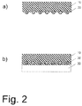
- the invention relates to a surface element having a front side and a rear side, which comprises a heating layer and a contacting layer, wherein the heating layer consists of an intrinsically heatable self-adhesive, which is formed as a conductor heating in passing an electric current, and wherein the contacting layer as an at least is formed substantially in a sheet-like spreading and interrupted by recesses contacting element and has a first side surface and a second side surface, wherein the contacting layer via the first side surface is in contact with the heating layer and is electrically conductively connected thereto and the use of this surface element.
- the invention further relates to a method for bonding such a surface element to a bonding substrate.
- electric heaters are used to heat objects or rooms.
- heat is obtained as thermal energy by conversion of electrical energy (including magnetic energy).
- Electric heaters can basically be based on different technical principles.
- heat generation based on capacitive or inductive effects or electromagnetic radiation heating systems have prevailed that contain Schuwiderstandsetti (so-called resistance heaters).
- resistance heaters the heat energy (Joule heat) produced by passing an electric current through the heating resistor element is utilized.
- any electrical conductor may be used as a heating resistance element having a non-zero finite resistance value.
- the selection of the heating resistor element results from the heat output to be achieved; this is dependent on the resistance value of the heating resistor element and on the electrical current flowing through the heating resistor element and thus also on the applied voltage in accordance with Ohm's law. Accordingly, the selection of the heating resistor element is carried out according to the nature of the existing therein cable routes, approximately according to their cross-section, length, resistivity and thermal capacity.
- resistance heaters are increasingly used, for example for heating car seats, window panes and automobile mirrors.
- resistance wires are laid planar in the simplest case.
- Other systems have as Bankwiderstandselement layered conductors, for example those of electrically conductive polymer layers.
- layered heating resistor elements can be glued to the rear side of the mirror glass of an automobile exterior mirror, which connect the mirror glass to a carrier plate in the holder of the automobile exterior mirror and are contacted over a large area via aluminum conductor surfaces. If a voltage is now applied to the heating resistor element, it heats up as a result of the current flow. The heat generated is transferred to the glass surface of the mirror via a double-sided pressure-sensitive adhesive tape, thus heating it. In this way, temperatures of 45 ° C to 80 ° C can be achieved on the glass surface of the mirror.
- Such a system of a carrier foil with conductor surfaces and intrinsically heatable ink is sufficient to achieve a heating, but requires a relatively complicated structure, since the individual components of the heating element not only have to be glued to the glass of the mirror, but also with the carrier plate the mirror, which in many cases consists of the plastic acrylonitrile / butadiene / styrene (ABS).
- ABS plastic acrylonitrile / butadiene / styrene
- such a pressure-sensitive adhesive tape which is used to attach a heating element to a mirror plate and which transports the heat from the heating element to the mirror surface, not only the highest possible thermal conductivity It must also be particularly adapted to thermal shock resistance at elevated temperatures and to weatherability and tack at low temperatures. This also applies to a separate adhesive layer which may be provided for attaching the composite tape of carrier film and conductive ink to the support plate of the mirror mount.
- such a composite tape is generally only slightly flexible and is therefore relatively rigid.
- the composite tape adheres poorly to a curved primer because the strength of the composite tape provides high mechanical resistance to deformation. This can lead to a local or full-surface detachment of the heating element from the bonding substrate (the primer or support), which reduces or even prevents the transmission of the electrically generated heat energy to the bonding substrate.
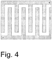
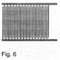
- the contacting element receives this a flexible nature and thus an increased resistance to fracture.
- the contacting element gains in flexibility parallel to the main extent (surface area, main extension plane) of the surface element in flexibility, so that the contacting element is flexible in a transverse force acting on the main expansion, without breaking under the resulting mechanical stress.
- the surface element according to the invention may not have a stabilizing carrier film, which would reduce its flexibility. With such a carrier-free surface element, it is therefore possible to achieve the desired flexibility.
- a disadvantage of these surface elements is the poor positioning and the lack of repositionability.
- the consequence of this is that an exact alignment of the surface element on the primer before bonding is not readily possible (poor positioning).
- the bonded on the base adhesion-free surface element of the primer can not be replaced again, without the risk of damaging the filigree structure of the contacting element, so that its position can not be subsequently corrected (lack of repositioning).
- the latter is, among other things, the result of the decline in intrinsic stability, which is accompanied by the drastic increase in flexibility.
- the reduced stability is more problematic in a heating element than in a conventional adhesive tape, since damage to the surface element as a whole inevitably results in damage to the electrically conductive structures of this surface element, which can cause it to be impaired in its heating performance or even heating functionality completely loses.
- Damage to the surface element occurs especially during the preparation of the surface element for the bond. For example, it can also lead to the destruction of the surface element when removing protective films.
- Such protective films usually cover the adhesive surfaces of the surface element during storage in order to prevent inadvertent sticking in the storage state.
- a storage state storage form
- the state of a glued surface element is referred to, in which this is stored before the subsequent bonding, so for example as stacked sheets, as a wound-up roll and the like.
- the protective film is removed from the adhesive surface.
- the surface of the protective film is usually equipped adhesion-reducing, to facilitate the detachment of the surface element of the protective film.
- adhesion-reducing to facilitate the detachment of the surface element of the protective film.
- even such a reduction in adhesion is not sufficient in practice to reliably prevent damage to the surface element, especially since the carrier-free surface element should usually be as thin as possible.
- the DE 10 2007 007 617 A describes a sheet comprising at least one layer of an adhesive within which heat can be generated, wherein the adhesive is a hot-melt adhesive and a PTC thermistor.
- the surface element has a first self-adhesive side surface, a second self-adhesive side surface and a layer sequence comprising a heating layer, a contacting layer and the layer of adhesive layer
- EP 2 148 337 A describes a similar construction in which the heating layer is in contact with and electrically conductively connected to a first side surface of the contacting layer, and in which the adhesive layer is in contact with a second side surface of the contacting layer, and wherein the heating layer consists of an intrinsically heatable first Self-adhesive (10) is formed, which is formed as when passing an electrical current heating PTC thermistor.
- the adhesive layer consists of a second self-adhesive.
- the contacting layer is an at least substantially planar spread open contacting element.
- an object was to provide an improved intrinsically heatable and double-sided adhesive surface element which has a reduced adhesion to the protective film, without thereby impairing the subsequent bond strength.
- a surface element of the type mentioned in which the second side surface of the contacting layer forms the front of the surface element and in which also formed the recesses in the contacting element through the thickness of the contacting element throughout are present and at least in the region of the second side surface substantially free of adhesive.
- the first side surface is at least partially embedded in the intrinsically heatable self-adhesive.
- the second side surface of the contacting layer represents the front side of the surface element, it is ensured that in the stored state at the Front surface of the surface element at most little self-adhesive is present.
- the amount of adhesive there is also greatly reduced by the fact that the recesses in the contacting element are also substantially free of adhesive here, that is, that the recesses at least in the region of the second side surface, which forms the outer front of the surface element, no or at most only contain little self-adhesive.
- This ensures that the recesses on the front side of the surface element are virtually free of adhesive, so that the amount of self-adhesive mass located on the front side of the surface element is reduced. This makes it possible to bring the surface element with the primer in contact and align exactly before bonding is achieved.
- any adhesion to the protective film is also reduced, whereby it is possible to peel the protective film from the adhesive without impairing the functionality of the surface element thereof.
- the self-adhesive material can flow from the first side surface of the contacting layer through the recesses of the contacting element to the second side surface for contacting the surface element on both sides, where it can come into contact with the primer that a high bond strength is ensured even on the front side of the surface element which is virtually free of adhesive in the storage state as a result of the self-adhesive mass passed through.
- each layer is called containing an adhesive and adapted for adhesively bonding a sheet to a primer.
- each layer is called containing an adhesive and adapted for adhesively bonding a sheet to a primer.
- the functional layer being at least substantially sheet-like and is formed perforated by recesses and having a first side surface and a second side surface, wherein the functional layer via the first side surface is in contact with the self-adhesive composition layer in that the second side surface of the functional layer forms the front side of the surface element and that the recesses in the functional layer are formed continuously throughout the thickness of the functional layer and are free of adhesives at least in the area of the second side surface
- the surface element described above in turn forms a special embodiment in which the contacting element is provided as a non-adhesive layer.
- a surface element which can be adhesively bonded on both sides can also be realized according to the overall concept with a non-adhesive functional layer (for example a carrier), which consists of a flat structure provided with adhesive-mass-free recesses.
- a non-adhesive functional layer for example a carrier
- the planar structure may then have on only one of its two side surfaces a self-adhesive mass layer in which the planar structure is at least partially embedded.
- the intrinsically heatable self-adhesive is a PTC thermistor.
- a PTC PTC element
- PTC positive temperature coefficient
- PTC thermistors are electrically conductive materials whose resistance increases with temperature and thus conduct electricity better at lower temperatures than at high temperatures.
- PTC elements heating resistor elements
- PTC elements heating resistor elements
- overheating of the heating element is avoided when a constant voltage is applied to such a heating element because as the operating temperature increases, the resistance of the heating element increases Ohm's law, the current decreases in proportion to the increase in resistance, the total heat output decreases and the heating element cools down again.
- an intrinsic temperature limiting control can be used instead of or in addition to an external control.
- the self-adhesive composition comprises at least one electrically conductive filler in addition to the features of one or more of the aforementioned embodiments.
- the electrically conductive filler is selected from the group comprising graphite, carbon nanoparticles and carbon black, in particular Leitruß.
- the advantage of such a composition is that these fillers form a particularly good bond with the polymer matrix, so that such an adhesive as a whole has a high degree of cohesion and is therefore capable of strong mechanical loading.
- the first side surface of the contacting layer is at least partially embedded in the intrinsically heatable self-adhesive composition.
- the contacting layer on the surface element not only in the bonding state (which differs from the storage state primarily in that the self-adhesive passes through the recesses to the front of the surface element and thus surrounds the contacting element), but already fixed in the storage state, so that an unintentional detachment of the contacting element is more effectively prevented.
- the recesses are at least substantially free of adhesive mass at least in the region of the second side surface.
- the thickness of the contacting element is at most 50 ⁇ m or even at most 20 ⁇ m. With such a thickness, it is ensured that the self-adhesive masses can flow through the contacting layer during the bonding of the planar element and can completely fill in the recesses of the contacting element so as to offer a maximum of bond strength.
- the recesses make up at least 25% of the area of the first side surface of the contacting layer, preferably more than 50% of the area of the first side surface of the contacting layer or even more than 75% of the first side surface of the contacting layer.
- the passage area for the self-adhesive is sufficiently large to allow a high-strength bond.
- the recesses can take a smaller area; For example, in mechanically weakly loaded connections, the recesses can account for only 10% of the area of the first side surface of the contacting layer.
- the perforated contacting element may have web-shaped regions.
- the flexibility of the contacting layer and thus also of the surface element is increased overall in the main extension plane (in particular transversely to the orientation of the web-shaped regions), at the same time a high stability is ensured, in particular parallel or obliquely to the alignment of the web-shaped regions. Since the web-shaped arrangement of the contacting layer can lead to the recesses also having an elongate shape, moreover, the resistance which the contacting element of the self-adhesive agent encounters when passing through the recesses can be reduced, and thus the passage of the self-adhesive compound during bonding can be facilitated.
- the web-shaped regions of the perforated contacting element are present in a branched comb structure or finger structure.
- a comb structure as well as in a finger structure (interdigital structure) individual tines or fingers branch off from a main strand.
- the main strand may in this case have a larger cross section than the tines or fingers or the same cross section.
- a comb structure and a finger structure
- the branching elements are arranged at a comb structure on the same side of the main strand, while in a finger structure they branch off on different sides.
- Both structures can have both simple and multiple branches and thereby both regular and irregular arrangements and can be used as a single electrode as well as in an embodiment of the contacting element as a plurality of electrodes within the contacting layer both in an embodiment of the contacting element.
- the present invention provides a method for bonding such a sheet member to at least one bonding substrate by first contacting the sheet member with the bonding substrate such that the second side surface of the bonding layer contacts a portion of the surface of the bonding substrate, thus forming a loose pre-bond then the intrinsically heatable self-adhesive passes through the recesses of the contacting element and at least partially fills it, and finally the front side of the planar element is glued to the bonding substrate via the intrinsically heatable self-adhesive passed through the recesses.
- Such a bonding method is specially adapted to the surface element according to the invention and uses its structure in a special way by the self-adhesive reaches the front of the surface element only in the course of the second step and therefore this side of the surface element is adhesive only at the time of bonding.
- the use of this method allows a particularly simple process management during bonding and also ensures that the only one-sided adhesive surface element can be bonded on both sides in the storage form without application of a further adhesive.
- the self-adhesive passes through the recesses of the contacting element as a result of the action of force and thus reaches the front side of the surface element.
- all suitable forces can cause the passage of the self-adhesive composition, such as the passage of a viscous self-adhesive by gravity, as a result of interfacial forces or due to capillary forces.
- the penetration can be improved by temporarily reducing the viscosity of the self-adhesive composition; This can be achieved in a particularly simple manner if the pre-composite of surface element and adhesive substrate for passing through the intrinsically heatable self-adhesive mass is heated by the recesses of the contacting element
- the invention relates to a surface element with a front and a back.
- a surface element in the context of this application, in particular all conventional and suitable structures apply with substantially sheet-like extent. These allow a surface bonding and can be configured differently, especially flexible, as an adhesive film, adhesive tape, adhesive label or as a form punching.
- the terms front and back refer to the two surfaces of the surface element parallel to its main extent and serve only to distinguish these two arranged on opposite sides of the surface element surfaces, without that the choice of terms, the absolute spatial arrangement of the two surfaces is fixed; Consequently, the front side can also represent the spatially rearward side surface of the surface element, namely, accordingly, when the back side forms its spatially front side surface.
- the surface element contains two different layers, a heating layer and a contacting layer.
- a layer is in particular a planar arrangement of a system of uniform functionality, the dimensions of which are significantly smaller in one spatial direction than in the other two spatial directions which define the main extent.
- Such a layer can be made compact or perforated and consist of a material or of different materials, in particular if they contribute to the uniform functionality of this layer.
- a layer may have a constant thickness over its entire areal extent or different thicknesses.
- a layer may also have more than one functionality.
- each layer is designated, which is set up to heat the surface element.
- the contacting layer is any layer which conducts the electrical current well, with the aid of which a voltage can be applied to the heating layer and / or a current can be conducted through at least a portion of the heating layer; the contacting layer thus serves to connect external electrical supply lines to the surface element (contacting electrode function).
- the contacting layer is formed as a contacting element which is at least substantially planar and which is interrupted by recesses.
- an element made of a material which conducts electrical current is referred to as the contacting element, the structure of which at least in a subregion conducts the current continuously electrically.
- "Spread out at least substantially in the form of a sheet" means that the subregions of which the contacting layer is composed lie within the layer in a planar one Arrangement are present, with individual subregions can also protrude from this planar arrangement.
- the contacting layer may be formed in one piece or in several parts.
- the contacting layer is an electrically conductive connection between the heating layer and the current source or voltage source.
- the contacting layer can be formed either as one of the two electrode terminals (poles) of the heating layer or else form both electrode terminals. If the contacting layer represents only one of the two electrode terminals of the heating layer, then a second electrode connection is required so that a current can flow through the heating layer and the heating layer heats up.
- This second electrode terminal may be formed within the surface element according to the invention - for example in the form of an additional second flexible contacting layer - or be provided on one of the two bonding substrates, for example as a metallic layer on the surface of a glass (such as the silver layer of a mirror).
- the contacting layer has a first side surface and a second side surface.
- the first side surface of the contacting layer and the second side surface of the contacting layer are the two side surfaces of the contacting layer, which are arranged parallel to their main extent.
- the contacting layer is not closed over the entire surface, but instead is perforated, so that this layer is discontinuous and has recesses (recesses) which also extend in a direction perpendicular to the main extent of the layer.
- the layer itself is not completely compact, but rather that the recesses in the contacting element are continuous throughout the thickness of the contacting element, ie extend through the layer (through holes).
- the contacting layer may optionally also have further recesses which are not continuous but are limited only to parts of the layer thickness (depressions, for example for better anchoring or for locally reducing the thickness of the contacting layer).
- the recesses may be arbitrarily shaped, such as regular or irregular, be of uniform or varying width, straight, oblique or curved wall sections and the like.
- the recesses may extend in different directions in the contacting layer or may have a particular preferred direction, so that their main extent extends at least substantially in one spatial direction. In the latter way, a particularly high flexibility of the contacting layer and thus also of the planar element in one direction can be achieved while minimizing the mechanical stability and the electrical contact cross-section. This may be particularly useful, for example, if the surface element is to be fastened to a cylinder jacket-like surface which is strongly curved in one direction and has a small radius of curvature.
- the recesses are present at least in the region of the second side surface substantially free of adhesive.
- the first side surface is at least partially embedded in the intrinsically heatable self-adhesive. This includes those recesses which have no adhesive only in a small subarea in the immediate vicinity of the second side surface.
- a recess substantially free of adhesive in the region of the second side surface is a recess which, in the region of the second side surface and thus on the front side of the surface element, contains at most a small amount of self-adhesive, preferably even no self-adhesive.
- the recess contains a small amount of self-adhesive, then the amount must be so small that this self-adhesive compound results in a possibly very weak adhesive action on the front side of the surface element, and preferably does not protrude out of the recess there.
- the recesses may account for any proportion of the surface area of the contacting layer, and for practical reasons, in particular an area fraction of at least 25% of the area of the first side surface of the contacting layer has proven favorable, preferably more than 50% of the area the first side surface of the contacting layer or even more than 75% of the first side surface of the contacting layer.
- the perforated contacting element may be designed differently with regard to the specific configuration of the depressions, for example as a broken surface, as a folded or branched wire structure or the like.
- This also includes a structure in which the contacting element has web-shaped regions.
- the dimension in one direction (the length of the respective web-shaped area) is considerably larger than in the other two directions, wherein in contrast to a wire-shaped structure also whose dimension in a second direction (the width of the respective web-shaped area) is greater than its dimension in the third direction (the thickness of the respective web-shaped area).
- the dimensions of the web-shaped regions can in principle be chosen as desired, with a width of not more than 5 mm or even less than 1 mm being found to be favorable for the width thereof.
- a web-shaped region can be formed regularly or irregularly.
- a web-shaped region can thus be formed, for example, by a flat cuboid section, by a circular section, a circular ring section or else completely irregularly shaped.
- the web-shaped shape of the subregions of the contacting element may also result in a web-shaped form of the recesses, however, other embodiments may come into question for this purpose.
- the web-shaped regions of the contacting element can be present in a superordinate structure, for example in a single or multiple branched comb structure or finger structure.
- Non-metallic conductors such as metal oxides (for example indium-tin oxide) or intrinsically conductive polymers can also be used according to the invention, provided they are structured accordingly.
- the Contacting layer preferably has a mean or even maximum thickness of less than 50 ⁇ m, preferably less than 20 ⁇ m or even less than 10 ⁇ m.
- the areas of the contacting element which conduct the electric current may be of any desired design, for example conductively connected to one another (all areas or only a portion of the areas) or present as a single area of the contacting element, which is not conductively connected to the other areas via the contacting element.
- a part of the areas may be connected to one another in an electrically conductive manner and another part of the areas may be present individually. Of course, this does not exclude an electrically conductive connection via the heating layer.
- the perforated contacting element has two or more partial regions which are not electrically conductively connected to one another via the perforated contacting element, then it is possible to realize both electrical contacts (electrodes or poles), which are required for a heating effect of the heating layer, within the contacting element in order to be able to dispense with further current-conducting layers outside the surface element and to facilitate the final assembly of the surface element to the bonding substrates.
- the contacting element contains two regions which are not connected to one another and which are formed as the two electrode leads (poles) of the heating layer.
- the entire contacting element is continuously conductive, then this is used as one of the two poles of the heating layer, wherein a current flow through the heating layer then occurs mainly in a direction perpendicular to the main extent, whereas in an arrangement in which the contacting element represents both electrode terminals, in addition to the vertical current flow or instead of a lateral current flow occurs within the main extent.
- the contacting layer is arranged on one side of the heating layer, in that the contacting layer is in contact with the heating layer via the first side surface and is electrically conductively connected thereto.
- the other side surface of the contacting layer, the second side surface forms the front side of the surface element in this arrangement. From this particular arrangement it follows that the front of the surface element is formed such that it is not tacky or at most only slightly sticky, so that a strong adhesion of the surface element is avoided at a protective state in the storage condition of the front cover.
- the direct contact between the first side surface and the heating layer is formed such that the first side surface of the contacting layer is at least partially embedded in the intrinsically heatable self-adhesive.
- Embedding is understood to be the arrangement of partial regions of the contacting layer within the outer boundary plane of the self-adhesive mass layer, these partial regions of the contacting layer touching the self-adhesive mass locally on several sides. This likewise includes that the first side surface of the contacting layer is embedded in the intrinsically heatable self-adhesive only in a partial region of the contact surface and merely abuts the other in the remaining regions of the contact surface.
- the heating layer is in contact with a first side surface of the contacting layer, so that these two layers touch directly, that is to say directly.
- the heating layer is electrically conductively connected to the first side surface of the contacting layer.
- a compound is referred to as electrically conductive in particular if the total electrical resistance of the compound to which the Contribute resistors of the sections to be connected and the contact resistance of the compound, at most of the same order of magnitude as the total resistance of the remaining conductive areas and contacts.
- the second side surface of the contacting layer forms one of the two outer sides of the surface element, namely its front side.
- the heating layer consists of an intrinsically heatable self-adhesive, which is formed as when passing through an electrical current is heated conductor.
- self-adhesives are understood to mean, without exception, all adhesives based on pressure-sensitive adhesives and / or hotmelt adhesives, ie adhesives which, on their own, permit permanent bonding to the substrate (the substrate, primer or adhesive foundation). "On the basis of” or “based on” means in this case that the adhesive properties of this adhesive system are at least greatly determined by the basic properties of this adhesive or adhesive components (the so-called base polymer), which of course is not excluded be additionally influenced by using modifying auxiliaries or additives or other polymeric adhesives in the adhesive system.
- Adhesive adhesives are understood as meaning those adhesives which, even at relatively low pressure, permit permanent bonding to the substrate at room temperature.
- hot melt adhesives are understood as meaning those adhesives which undergo permanent bonding to the substrate only at elevated temperatures, the bond thus obtained being retained even at a subsequent cooling of the bond to room temperature.
- the bondability of pressure-sensitive adhesives as well as hot-melt adhesives is based on their adhesive properties.
- Adhesion is usually referred to as the physical effect which brings about the cohesion of two phases brought into contact at their interface on the basis of intermolecular interactions occurring there.
- the adhesion thus determines the adhesion of the adhesive to the substrate surface and can be determined as initial tack (the so-called tack) and as bond strength.
- plasticizers and / or adhesion-increasing resins are frequently added to the adhesive.
- Cohesion is usually the physical effect that results in the internal cohesion of a substance or mixture due to intermolecular and / or intramolecular interactions.
- the cohesive forces thus determine the viscosity and flowability of the adhesive, which can be determined as viscosity and shearing life, for example.
- these are often subjected to additional crosslinking, for which reactive (and thus crosslinkable) components or other chemical crosslinkers are added to the adhesive and / or the adhesive is exposed to actinic (high-energy) radiation in a post-treatment.
- the adhesive properties of a PSA are determined primarily by the ratio of adhesive and cohesive properties. For example, it is important for some applications that the adhesives used are highly cohesive, ie have a particularly strong internal cohesion, while for other applications a particularly high adhesion is required.
- pressure-sensitive adhesives allows a particularly simple bonding, without the need for further process steps such as heating of the surface elements, so that such self-adhesives can also be used in a primer that has a highly irregular geometry or is heat-sensitive.
- hot-melt adhesives are used, a particularly high bond strength can be achieved, which is why these systems are used in particular where the bond is exposed to strong mechanical loads.
- the self-adhesive composition of the heating layer is formed intrinsically heatable.
- an intrinsically heatable layer is any layer that is electrically heatable by itself, that is, that this layer without other components or components in the layer is capable of passing an electrical current through the layer or upon application of an electrical voltage to the layer itself produce heat, it is irrelevant whether the current or the voltage is an AC or an AC voltage or a DC or DC voltage.
- heating layer it is possible in principle to use all self-adhesive compositions which conduct an electric current flowing through this self-adhesive essentially without decomposition.
- the heat within the heating layer is generated from the voltage drop due to the electrical resistance in this layer itself, but heating can also be achieved on the basis of other effects, such as by another electrothermal transducer or by an electrically initiated exothermic chemical reaction.
- such surface elements may be configured once or multiple times; likewise, the heat generation process can be carried out once or several times.
- Such a heating layer may have a (mean) thickness of less than 1 mm perpendicular to the main extent, preferably a thickness from a range of 10 ⁇ m to 400 ⁇ m, particularly preferably from a range of 20 ⁇ m to 200 ⁇ m.
- a (mean) thickness of less than 1 mm perpendicular to the main extent preferably a thickness from a range of 10 ⁇ m to 400 ⁇ m, particularly preferably from a range of 20 ⁇ m to 200 ⁇ m.
- Such a configuration of the heating layer ensures optimum properties, since the heating layer is on the one hand thick enough to provide a sufficiently high heating power, on the other hand thin enough to rapid heat conduction within the heating layer and good mechanical properties in terms of flexibility and cohesion guarantee.
- this may have an electrical resistance, on the one hand high enough to allow heating of the layer, on the other hand low enough to establish a flow of current through the layer at all.
- This heating layer can also be cold-conducting, that is, have a positive temperature coefficient with regard to their electrical resistance and thus exhibit a PTC effect.
- the layer is preferably designed such that the heat generation in the heating layer is limited by the PTC effect for the respective operating voltage and the respective operating current, so that the layer behaves self-regulating with respect to heat generation and in particular one does not exceed the set temperature limit. Overheating of the surface element can thus be avoided.
- the self-adhesive composition used is preferably a pressure-sensitive adhesive or hot-melt adhesive which comprises at least one electrically conductive filler as electrically conductive material.
- electrically conductive filler is a Admixed to a self-adhesive, the electrical current either already on its own (ie without self-adhesive) or even in the mixture with the self-adhesive.
- fillers which are compatible with the particular self-adhesive composition can be used as the filler.
- fillers are used which are selected from the group comprising graphite and carbon black, in particular conductive carbon black (for example Printex TM XE from Degussa), and any desired combinations thereof.
- carbon-based fillers may also be used, in particular those which are nanoscale, ie have an extension of not more than 500 nm, preferably less than 200 nm or even less than 50 nm, in at least one spatial dimension
- carbon nanoparticles such as carbon nanotubes (for example, carbon nanotubes from Ahwahnee or carbon nanotube masterbatches from Hyperion Catalysis), carbon nanofibres, fullerenes and the like.
- the filler is used in such an amount that the proportion of the filler in the self-adhesive is large enough to ensure sufficient conductivity of the self-adhesive, but that on the other hand is low enough to affect the mechanical properties of the self-adhesive only slightly.
- a combination of different types of fillers can be advantageous, since sufficient electrical conduction properties-for example, cold-conduction properties-can be achieved at the lowest possible degree of filling, in particular when combining carbon nanotubes with carbon black or graphite.
- the fillers can be used surface-modified.
- specific properties of the self-adhesive composition can be influenced in a targeted manner, for example in order to improve the dispersibility of carbon nanotubes or carbon black in the self-adhesive composition.
- the surface of the conductive fillers, such as the soot particles may be completely or partially covered with metals such as nickel, silver or gold, with silanes or with formamides.
- the conductivity and thus the achievable temperature and heating rate depends inter alia on the degree of filling of the conductive filler, that is the Mass fraction in the self-adhesive.
- the degree of filling is advantageously between 1 and 60 wt .-%. Very preferably between 5 and 30% by weight of filler are used.
- the electrically conductive fillers may be admixed with the monomers of the self-adhesive composition prior to the polymerization and / or during the polymerization and / or mixed with the polymers only after the polymerization has ended.
- the conductive filler is added after polymerization to a melt of a base polymer of the self-adhesive.
- the electrically conductive filler is preferably introduced directly into the melt.
- a homogeneous incorporation in the inventive sense is desirable.
- Homogeneous distributions of the filler in the self-adhesive composition are preferably achieved by compounding in twin-screw extruders, continuous kneaders (for example Buss kneaders) or planetary roller extruders.
- the self-adhesive composition is also intended to be cold-conducting, it is possible in principle to use all polymers with suitable adhesive properties which have a PTC effect have, so behave cold.
- the occurrence and extent of a PTC effect depends on network formation, for example on whether the conductive filler itself is agglomerated or not.
- the PTC effect can be assisted inter alia by orientations within the polymer constituents of the self-adhesive composition introduced during the production process, for example by introducing anisotropy with regard to physical properties and / or with regard to the alignment of the macromolecules.
- thermoplastics such as polyethylene, polyvinylidene fluoride, hexafluoropropylene or tetrafluoroethylene are used.
- the state of the art is in DE 29 48 350 A1 .
- EP 0 512 703 A1 such as EP 0 852 801 A1 described in detail, whose technical teaching is explicitly included here.
- PTC thermistors can be applied in the form of an ink on a continuous conductor surface which serves as an electrical contacting electrode and which are arranged on a separate carrier film of a thickness of usually 75 microns to 250 microns. The solvent contained in the ink is removed in a subsequent drying step.
- Such inks are in EP 0 435 923 A1 described in detail.
- a cold-conducting self-adhesive is used with an electrically conductive filler, then it has proven advantageous to use multiphase systems, in particular those in which at least one phase in the temperature range in which the PTC effect occurs, as a result of heating undergoes a volume expansion which, according to the currently generally accepted scientific explanation, is at least partially responsible for the cold conduct (see J. Meyer in Polymer Engineering and Science, 13 (1973), pp. 462-468 ).
- Self-adhesive compositions based on polymers or polymer blends which have one or more further fillers in addition to the conductive filler, are also considered to be multiphase in the sense of the invention.
- Such self-adhesive compositions which have partially crystalline polymers has proved to be particularly advantageous.
- Semi-crystalline polymer systems which can be used are both single-phase and multiphase systems, both homopolymers and copolymers, in particular semicrystalline block copolymers.
- the Semicrystalline polymers may be part of the base polymer itself or may be an aggregate.
- the crystalline subregions of such partially crystalline polymers exhibit a greater thermal expansion when softening the polymer matrix than their amorphous regions.
- the hotmelt adhesive and / or the PSA in the heating layer preferably contains at least 30% by weight of semicrystalline polymers, even better is a proportion of partially crystalline polymers of at least 50% by weight in the self-adhesive composition. It has been found that, especially with hot melt adhesives, the suitability for achieving the PTC effect increases surprisingly strongly with the proportion of partially crystalline polymers. On the other hand, pressure-sensitive adhesives lose their pressure-sensitively adhesive properties as the partially crystalline portion increases, so that the proportion of partially crystalline polymers is lower when pressure-sensitive adhesives are used than with hot-melt adhesives in order to ensure sufficiently high pressure-sensitive adhesiveness.
- Hotmelt adhesives are well suited for exploiting the PTC effect beyond expectations.
- Hotmelt adhesives of partially crystalline polymers which are contained in the base polymer of the adhesive at 100% by weight or which are at least approximately 100% by weight in the adhesive are found to be particularly advantageous as self-adhesive compositions.
- a hot-melt adhesive and / or PSA as self-adhesive are advantageous in which the degree of crystallinity is more than 20% or even more than 40%.
- the degree of crystallinity can be determined by Differential Scanning Calorimetry (DSC).
- polyolefins for example low-density polyethylene
- copolymers of polyolefins for example ethylene-vinyl acetate (EVA), ethylene-acrylic acid (EAA), ethylene-methacrylic acid (EMAA), ethylene-ethyl acrylate or ethylene-butyl acrylate
- EVA ethylene-vinyl acetate
- EAA ethylene-acrylic acid
- EEMA ethylene-methacrylic acid
- ionomers polyamides and / or copolymers thereof.
- acid-modified (for example with maleic acid or maleic anhydride) polyolefins or their copolymers are preferred in the field of semicrystalline thermoplastics, since these are particularly compatible with the conductive fillers such as carbon black or carbon nanotubes and using these polymers particularly simple homogeneous dispersions of the filler in the polymer matrix.
- Very particularly preferred block copolymers are styrene block copolymers such as SBS (styrene-butadiene-styrene block copolymers), SIS (styrene-isoprene-styrene block copolymers), SEBS (styrene-ethylene-butylene-styrene block copolymers) or SEPS (styrene-styrene block copolymers). Ethylene-propylene-styrene block copolymers).
- SBS styrene-butadiene-styrene block copolymers
- SIS styrene-isoprene-styrene block copolymers
- SEBS styrene-ethylene-butylene-styrene block copolymers
- SEPS styrene-styrene block copolymers
- polymeric or inorganic fillers that support the PTC effect during their heating with their melting.
- These may be, for example, highly crystalline polyolefin waxes or ionic liquids (low-melting metal salts).
- pressure-sensitive adhesives are adhesives if they have pressure-sensitive adhesive properties in accordance with "Handbook of Pressure Sensitive Adhesive Technology" by Donatas Satas (van Nostrand, New York 1989).
- n the number of runs via the monomers used
- w n the mass fraction of the respective monomer n (wt .-%) and T G, n the respective glass transition temperature of the homopolymer of the respective monomers n in K.
- Adhesive adhesives for the self-adhesive composition therefore include, for example, PSAs based on acrylates and / or methacrylates, silicones, natural rubbers and / or synthetic rubbers.
- PSAs based on acrylates and / or methacrylates silicones, natural rubbers and / or synthetic rubbers.
- Such pressure-sensitive adhesives have the advantage that the adhesive properties of the surface element can be controlled to a large extent and thus can be adjusted specifically to the specific conditions of the bond to be achieved, for example with regard to the respective primer or the ambient conditions.
- PSAs based on acrylic acid and / or methacrylic acid and / or based on esters of the abovementioned compounds or those based on hydrogenated natural or synthetic rubbers since they are particularly resistant to aging and thus able to withstand repeated heating processes of the surface element according to the invention for a long time ,
- Acrylate PSAs are particularly suitable which are obtainable, for example, by free-radical polymerization and which are based at least in part on at least one acrylic monomer of the general formula CH 2 CC (R 1 ) (COOR 2 ), where R 1 is H or a CH 3 radical and R 2 is H or is selected from the group of saturated, unbranched or branched, substituted or unsubstituted C 1 - to C 30 -alkyl radicals.
- the at least one acrylic monomer should have a mass fraction of at least 50% by weight in the pressure-sensitive adhesive.
- the at least one acrylic monomer (a1) has a mass fraction of 65% by weight to 100% by weight and the at least one comonomer (a2) has a mass fraction of 0% by weight to 35% by weight in the self-adhesive composition ,
- an average molecular weight M w (weight average) of the self-adhesive composition of not more than 800,000 g / mol has proven to be advantageous, in particular with regard to the desired mechanical properties of the PSA.
- the self-adhesive composition according to a further embodiment may also comprise or be based on natural or synthetic rubber compositions.
- the natural rubber is degraded to a freely selectable molecular weight and, in the meantime, or additized with the electrically conductive filler.
- Semi-crystalline polymers such as EVA (ethylene-vinyl acetate) or polyolefins and copolymers thereof, in particular, may also be used as a special pressure-sensitive adhesive Block copolymers, used as a self-adhesive or added to this.
- EVA ethylene-vinyl acetate
- Block copolymers used as a self-adhesive or added to this.
- these adhesive composition systems provide additional support for the PTC effect.
- methyl acrylate methyl methacrylate, ethyl acrylate, n-butyl acrylate, n-butyl methacrylate, n-pentyl acrylate, n-hexyl acrylate, n-heptyl acrylate, n-octyl acrylate, n-octyl methacrylate, n-nonyl acrylate , Lauryl acrylate, stearyl acrylate, behenyl acrylate and branched isomers thereof, for example, isobutyl acrylate, 2-ethylhexyl acrylate, 2-ethylhexyl methacrylate, isooctyl acrylate or isooctyl methacrylate.
- cycloalkyl radicals may also be substituted, for example by C 1 - to C 6 -alkyl groups, halogen atoms or cyano groups.
- Specific examples are cyclohexyl methacrylate, isobornyl acrylate, isobornyl methacrylate and 3,5-dimethyl adamantyl acrylate.
- acrylic monomers and / or comonomers are used which have one or more substituents, in particular polar substituents, for example carboxyl, sulfonic acid, phosphonic acid, hydroxyl, lactam, lactone, N-substituted amide, N, substituted amine, carbamate, epoxy, thiol, alkoxy, cyano, halide and ether groups.
- substituents for example carboxyl, sulfonic acid, phosphonic acid, hydroxyl, lactam, lactone, N-substituted amide, N, substituted amine, carbamate, epoxy, thiol, alkoxy, cyano, halide and ether groups.
- comonomers (a2) are moderately basic comonomers such as mono- or di-N-alkyl-substituted amides, in particular acrylamides.
- moderately basic comonomers such as mono- or di-N-alkyl-substituted amides, in particular acrylamides.
- comonomers (a2) are hydroxyethyl acrylate, hydroxyethyl methacrylate, hydroxypropyl acrylate, hydroxypropyl methacrylate, allyl alcohol, maleic anhydride, itaconic anhydride, itaconic acid, glyceridyl methacrylate, phenoxyethyl acrylate, phenoxyethyl methacrylate, 2-butoxyethyl acrylate, 2-butoxyethyl methacrylate, cyanoethyl acrylate, cyanoethyl methacrylate, glyceryl methacrylate, 6-hydroxyhexyl methacrylate, vinyl acetic acid , Tetrahydrofurfuryl acrylate, beta-acryloyloxypropionic acid, trichloroacrylic acid, fumaric acid, crotonic acid, aconitic acid, dimethylacrylic acid, although this list is not exhaustive.
- comonomers (a2) used are vinyl compounds, in particular vinyl esters, vinyl ethers, vinyl halides, vinylidene halides, vinyl compounds having aromatic rings and heterocycles in the alpha position, non-limiting examples being vinyl acetate, vinylformamide, vinylpyridine, ethyl vinyl ether, vinyl chloride, vinylidene chloride, Styrene and acrylonitrile may be mentioned.
- the at least one comonomer (a2) may be a photoinitiator having a copolymerizable double bond, in particular selected from the group consisting of Norrish I photoinitiators or Norrish II photoinitiators, benzoin acrylates or acrylated benzophenones.
- additional monomers are added to the described comonomers (a2) which have a high static glass transition temperature.
- additional monomers are aromatic vinyl compounds such as styrene are suitable, wherein preferably the aromatic nuclei consist of C 4 - to C 18 blocks and may also contain heteroatoms.
- Particularly preferred examples are 4-vinylpyridine, N-vinylphthalimide, methylstyrene, 3,4-dimethoxystyrene, 4-vinylbenzoic acid, benzylacrylate, benzylmethacrylate, phenylacrylate, phenylmethacrylate, t-butylphenylacrylate, t-butylphenylmethacrylate, 4-biphenylacrylate and 4-biphenylmethacrylate, 2- Naphthyl acrylate and 2-naphthyl methacrylate and mixtures of these monomers, although this list is not exhaustive.
- the surface element according to the invention for the self-adhesive composition may also contain hot-melt adhesive compositions.
- hot-melt adhesive in the sense of the present invention is a surface element according to the invention if, after the melt-applied application to the primer and subsequent cooling, the bond strength at room temperature according to ASTM D 3330-04 (at a withdrawal speed of 300 mm / min on the adherend to be bonded) is greater than 1 N / cm, in particular greater than 3 N / cm or even greater than 5 N / cm.
- Hot melt adhesives which can be used are all customary and suitable hotmelt adhesives, for example those based on synthetic rubbers, thermoplastic materials, elastomers with modifying resins, acrylic acid-vinyl copolymers and acrylate-containing block copolymers.
- the self-adhesives used for the surface elements of the invention are typically additionally crosslinked, with high crosslinking levels being sought, which in particular also enhance the PTC effect (cf. EP 0 311 142 A1 such as US 4,775,778 A ) and are therefore particularly suitable for the self-adhesive.
- Crosslinking also eliminates or reduces the effects of the negative temperature coefficient (NTC) effect, which is sometimes observed at temperatures above the melting point of the self-adhesive.
- NTC negative temperature coefficient
- a base polymer of the self-adhesive composition preferably has a degree of crosslinking which corresponds to at least a gel value of 35%, in particular of more than 60%.
- the gel value is understood to mean the ratio of the proportions of a base polymer which are not soluble in a suitable solvent (for example toluene or xylene) to the sum of soluble fractions and insoluble fractions of the base polymer.
- a high degree of crosslinking can be obtained, for example, in a crosslinking step with electron beams.
- Typical irradiation devices which can be used are linear cathode systems, scanning systems or segmented cathode systems, if these are electron beam accelerators.
- Typical acceleration voltages are in the range between 50 kV and 500 kV, preferably in the range between 80 kV and 300 kV.
- the applied waste cans range between 5 kGy to 150 kGy, in particular between 20 kGy and 100 kGy. Other methods can also be used which enable high-energy irradiation.
- a variation of the electrical conductivity and thus of the thermal heating via the degree of crosslinking can be effected.
- elevating The electron beam dose (and thus an increase in the degree of crosslinking) acting in a crosslinking reaction can be used to increase the electrical conductivity, so that the attainable temperature of the self-adhesive composition increases with a constant current flow through the heating layer of the planar element.
- the degree of crosslinking can be used to control the cold-conducting behavior of the self-adhesive composition.
- crosslinking agents and / or crosslinking promoters are, for example, bifunctional or multifunctional acrylates or methacrylates or triallyl cyanurates and triallyl isocyanurates.
- thermally activatable crosslinkers bifunctional or multifunctional epoxides, hydroxides, isocyanates or silanes are preferably mixed.
- a self-adhesive composition may of course comprise other formulation ingredients and / or additives such as auxiliaries, pigments, rheological additives, adhesion-improving additives, plasticizers, resins, elastomers, antioxidants, light stabilizers, UV absorbers and other auxiliaries. and additives, for example desiccants (such as molecular sieve zeolites or calcium oxide), flow and leveling agents, wetting agents such as surfactants or catalysts and heat-conductive fillers, heat-storing fillers or additives which are released by heat or whose release is assisted by heat.
- desiccants such as molecular sieve zeolites or calcium oxide
- flow and leveling agents such as molecular sieve zeolites or calcium oxide
- wetting agents such as surfactants or catalysts and heat-conductive fillers, heat-storing fillers or additives which are released by heat or whose release is assisted by heat.
- auxiliaries all finely ground solid additives such as chalk, magnesium carbonate, zinc carbonate, kaolin, barium sulfate, titanium dioxide or calcium oxide can be used. Further examples are talc, mica, silicic acid, silicates or zinc oxide. Of course, mixtures of the substances mentioned can be used.
- the pigments used may be organic or inorganic in nature. There are all types of organic or inorganic color pigments in question, for example, white pigments such as titanium dioxide for improving the light and UV stability or metal pigments.
- rheological additives examples include fumed silicas, phyllosilicates (for example bentonites), high molecular weight polyamide powders or powders based on castor oil derivatives.
- Additives for improving the adhesion may be, for example, substances from the groups of polyamides, epoxides or silanes.
- plasticizers for improving the bondability are phthalic acid esters, trimellitic acid esters, phosphoric acid esters, adipic esters and esters of other acyclic dicarboxylic acids, fatty acid esters, hydroxycarboxylic esters, alkylsulfonic acid esters of phenol, aliphatic, cycloaliphatic and aromatic mineral oils, hydrocarbons, liquid or semi-solid rubbers (for example nitrile rubbers or polyisoprene rubbers), liquid or semi-solid polymers of butene and / or isobutene, acrylic esters, polyvinyl ethers, liquid and soft resins based on the raw materials, which also form the basis for tackifying resins, wool wax and other waxes, silicones and polymer plasticizers such as polyesters or polyurethanes.
- plasticizers for improving the bondability are phthalic acid esters, trimellitic acid esters, phosphoric acid esters, adipic esters and esters of
- Aggregates that are released by heat or whose release is assisted by heat are those systems that contain an active substance that is released or activated as a result of the action of heat, so that a controlled release of this active substance is possible.
- active substance is any substance in question, which develops a special effect in the thermal release or activation, for example, a dye, a medical or cosmetic agent or a detonator (initial explosive).
- the effect may occur, for example, as a result of the release of the substance (for example with a topically applicable active substance) or during thermal activation, for example a thermally initiated chemical reaction (for example a molecular rearrangement, a crosslinking reaction or a decomposition) or a thermally initiated physical process (for example, adsorption / desorption or a phase transition).
- the heat-releasable additive may be a topically applicable medicinal agent encapsulated in a fusible matrix.
- resins may be added to the self-adhesive compositions according to the invention.
- tackifying resins the adhesive increasing resins
- all compatible with the corresponding base polymer (soluble) resins can be used, in particular reference is made to all aliphatic, aromatic, alkylaromatic hydrocarbon resins, hydrocarbon resins based on pure monomers, hydrogenated hydrocarbon resins, functional hydrocarbon resins and natural resins.
- resins are used which do not reduce the electrical conductivity and the heatability, even over an extended period of time.
- a further advantageous embodiment of the surface element can be achieved by adding a heat-storing filler to at least one of the layers.
- a heat-storing filler to at least one of the layers.
- Fillers with high heat capacity are, for example, aluminum, beryllium, boron, calcium, iron, graphite, potassium, copper, magnesium, phosphorus or compounds of the abovementioned substances, in particular aluminum oxide and aluminum chloride, calcium carbonate, calcium chloride, copper sulfate, magnetite , Hematite, magnesium carbonate and magnesium chloride, phosphorus chloride or phosphorus oxide (these substances can also fulfill other functions within the surface element, such as potassium or phosphorus in detonators).
- At least the self-adhesive composition layer has a high thermal conductivity, in particular of at least 0.5 W / m ⁇ K, very particularly preferably of more than 1 W / m ⁇ K.
- a high thermal conductivity in particular of at least 0.5 W / m ⁇ K, very particularly preferably of more than 1 W / m ⁇ K.
- heat-conductive fillers in particular of electrically insulating but highly heat-conductive fillers such as boron nitride or aluminum oxide, since the latter does not influence the electrical properties.
- electrically conductive fillers with high thermal conductivity can also be used, for example silver, aluminum or copper.
- the surface element according to the invention can have further layers.
- the surface element can contain further adhesive layers, for example by providing a further self-adhesive on the side surface of the heating layer facing away from the perforated contacting element.
- This adhesive may also be any suitable pressure-sensitive adhesive or hot-melt adhesive, for example a self-adhesive with one of the base adhesives described above.
- the adhesive properties of the two side surfaces of the surface element can be decoupled from each other, so that it is possible to achieve a particularly high bonding stability overall, since the adhesives can be adjusted to the self-adhesive side surfaces of the surface element individually to the respective adhesive base, which is particularly of Significance is when the materials of the adhesive base to be connected to the front of the surface element and the adhesive base to be connected to the back of the surface element are greatly different, such as in the case of a glassy or metallic contacting element and a polyolefinic adhesive base.
- At least one layer of the heatable surface element is equipped with a mechanism which, when the surface element is heated for the first time, leads to a cohesion increase in the self-adhesive, the self-adhesive and / or optionally in a further self-adhesive.
- This can be achieved, for example, via an increase in the crosslinking density by means of a thermally initiated post-crosslinking, which is characterized in particular by the (intrinsic) heating of the surface element itself can be initiated.
- a surface element is therefore used in such a way that first the bond is produced with at least one bonding substrate and then the initial heating is carried out, during which a solidification of the bond sets.
- the surface element is formed carrier-free, since this maximum flexibility of the surface element is ensured at the same time minimum installation depth.
- a flexible permanent support can be provided in the surface element.
- This support can be used, for example, to improve the mechanical properties, such as the puncture resistance of the surface element as a whole.
- suitable support materials for example films of metal and / or plastics, textile surface elements (for example, fabrics, scrims, knitted fabrics, nonwovens) or combinations of such materials.
- These permanent carriers can be closed or fully open closed. If such a permanent carrier is provided, it is, however, according to the invention imperative that it is not in direct contact with the contacting element, but is at most arranged on the self-adhesive mass layer.
- the permanent support in addition to its high flexibility has a high thermal conductivity, in particular a thermal conductivity of at least 0.5 W / m • K or even more than 1 W / m • K.
- Particularly preferred materials are polymers filled with thermally conductive fillers such as boron nitride or aluminum oxide.
- Such permanent supports typically have a thickness of less than 50 microns, preferably less than 25 microns, so as not to affect the overall flexibility of the construction.
- the permanent carrier is formed as a polymeric foam, since this does not significantly affect the flexibility of the entire surface element.
- the surface element may have on its front side and / or on its rear side a temporary carrier as a protective film in order to improve the handling of the surface element before the gluing and during the gluing.
- a temporary carrier as a protective film in order to improve the handling of the surface element before the gluing and during the gluing.
- any separating cover material may be used, such as a release paper or a process liner, which at least partially covers one of the outer self-adhesives.
- a masking material for example, all siliconized or fluorinated films are suitable with a release effect, which are removable without residue.
- film materials which may be mentioned here are PP (polypropylene), BOPP (biaxially oriented polypropylene), MOPP (monoaxially oriented polypropylene), PET (polyethylene terephthalate), PVC (polyvinyl chloride), PUR (polyurethane), PE (polyethylene), PE / EVA (polyethylene Ethylene-vinyl acetate copolymers) and EPDM (ethene-propylene-diene terpolymers).
- release papers can also be used, for example glassine papers, Kraft papers or polyolefinically coated papers.
- cover materials which themselves have a high thermal conductivity, in particular of at least 0.5 W / m • K or even more than 1 W / m • K.
- Particularly preferred materials are polymers filled with thermally conductive fillers, such as boron nitride or alumina.
- the surface element thus comprises at least one layer within which heat can be generated, this layer being pressure-sensitive or hotmelt-tacky, and a discontinuous, electrically conductive layer which represents at least one electrode (one pole) of the contacting layer. It is important here that the contacting element has a self-adhesive only on one of its side surfaces. In the simplest case, the surface element is accordingly a corresponding layer of adhesive composition with a contacting layer arranged thereon.
- the polymeric pressure-sensitive adhesive layers or hot-melt adhesive layers of the surface element according to the invention can be produced by the conventional methods for producing polymeric surface elements according to the prior art. These include, for example, flat film extrusion, blown film extrusion, the calendering process, the coating from a solution, from a dispersion or from a monomeric or prepolymeric precursor of the polymer.
- the self-adhesive is usually first spread in layers, for example on a permanent carrier or temporary carrier, for example a cover material or a production carrier - a so-called process liner - which is separated again from the surface element during the process or at the latest at the end of the process ,
- the contacting element is applied to this self-adhesive mass layer.
- the surface element according to the invention in any other manufacturing method deviating therefrom, for example by first applying the contacting element to a temporary carrier, then bonding it to the self-adhesive, and then peeling off the temporary carrier from the contacting element.
- the contacting element For applying the contacting element to the self-adhesive or optionally the temporary carrier, all known methods can be used, such as the application (for example printing) of conductive paints, conductive pastes or conductive inks, the transfer of sheets, films or layers (for example those of metals) by means of hot stamping, Heat-sealing, laminating or laminating or the discontinuous application of mixtures of polymers and conductive fillers (for example polymer-carbon black compounds), in which case the contacting element must have a conductivity which is at least a factor of 10 higher than the conductivity of the intrinsically heatable self-adhesive.
- the heatable self-adhesive is contacted with an electrically conductive metal grid or metal net.
- metals are used which do not over a longer period or only slightly corrode.
- copper or aluminum is used, but also silver or gold contacts can be made.
- the metal can be deposited directly on the self-adhesive composition, for example by galvanic or vapor deposition methods or by laser methods, but it can also be laminated in the form of a continuous or perforated layer by being transferred from a process liner.
- a conductive ink, a conductive ink, an intrinsically conductive polymer or a polymer-conductive mixture printing methods are preferred, in particular about a screen printing, since the discontinuous contacting layers hereby can be particularly easily, variably and reproducibly applied.
- the pressure may be a solution, a dispersion or a melt; if appropriate, a subsequent curing step can be provided here.
- the surface element it may be particularly advantageous to carry out this by a process in which first of all an adhesive coating is produced from the self-adhesive (for example, by applying the adhesive to a temporary support) and then to the front side of the adhesive obtained layering the perforated contacting element is applied directly, which may optionally be done under pressure.
- the surface elements are used according to the invention for connecting two bonding substrates together or for joining two different subregions of a single bonding substrate. Since the surface element is indeed only one-sided self-adhesive in the storage form, but is formed on both sides bondable during bonding, it is adapted to adhesively bond the surfaces of two bonding substrates together. In particular, the surface element is used for the bonding of bonding substrates in the automotive industry and is used for example in automobiles, buses, railways, ships or aircraft.
- the surface element according to the invention can be present here as part of a bonding composite.
- An adhesive bond in the present case is any bond obtained by bonding a surface element and at least one bonding substrate, which is connected to a self-adhesive side surface of the surface element directly or via other components.
- a mirror pane is used as the bonding substrate, in particular the rear side of the mirrored side of a mirror pane, or-in the case of a transparent planar element-a pane, for example a display window or a windshield.
- the surface element according to the invention can be used for heating such a bonding composite.
- the surface element according to the invention for example as a mirror heating (exterior and interior mirrors), in a heatable interior trim (attachment, noise insulation, heating), for wiper water heating or freezing, for a tank heating (especially for diesel vehicles), for the heating of fuel pipes (at the same time as attachment ), in a heating system for defrosting systems (hydrofoil, possibly including fixing functions), in a steering wheel heater, for heating air heating (auxiliary heating when the engine is cold) or for intake air preheating (combustion air).
- any desired bonding methods can be carried out. Due to the special design of the surface element, however, it is necessary for the surface element to be first connected or at least brought into contact with a first adhesive substrate on its rear side before the front side can be connected to a second adhesive substrate, since the self-adhesive composition is then applied to the front side of the adhesive Surface element passes. Of course this includes not from the fact that first both bonding substrates are brought into contact with the surface element, before bonding is effected, since bonding of the front even with this simplified process management due to the structure of the surface element according to the invention takes place only after connecting the back with the first bonding substrate.
- the method of bonding the sheet to the second bonding substrate thus includes at least the following steps: the sheet is contacted with the (second) bonding substrate such that the second side surface of the bonding layer contacts a portion of the surface of the bonding substrate to form a loose pre-bond
- the intrinsically heatable self-adhesive passes through and fills the recesses of the contacting element at least partially, and the front side of the planar element is bonded to the second bonding substrate via the intrinsically heatable self-adhesive passed through the recesses.
- the second side surface of the contacting layer contacts a region of the surface of the bonding substrate without forming a stable adhesive connection with one another.
- this does not exclude that a prefixing can take place in which the surface element and the second bonding substrate detachably adhere to one another.
- a non-solid and thus loose pre-bond ie a composite before the actual bonding.
- the intrinsically heatable self-adhesive passes through the recesses of the contacting element, so it is a passage of the intrinsically heatable self-adhesive through the recesses of the contacting effected.
- the passage can be achieved arbitrarily. This can usually be done by bringing the first bonding substrate to the rear side of the surface element and bonding it to the surface.
- the first bonding substrate can either be brought into contact with the surface element in time before the second bonding substrate (so that the first bonding substrate is also part of the pre-bond) or only after the surface element has been brought into contact with be brought into contact with the second bonding substrate (so that the first bonding substrate does not become part of the pre-bond).
- the passage of the intrinsically heatable self-adhesive through the recesses of the contacting element can be assisted by the fact that the pre-composite of surface element and bonding substrate is pressed together. Instead of or in addition, the pre-composite of surface element and adhesive substrate can be heated. In this way, the self-adhesive passes through the contacting layer particularly quickly.
- passage can also be achieved without the use of the first adhesive substrate, for example by arranging the pre-bond with the second adhesive substrate downward and the self-adhesive inherently flows through the recesses in the contact element as a result of the action of gravity;
- this requires a sufficiently low-viscosity self-adhesive and suitable recesses.
- An effect similar to the effect of earth gravity could also be achieved, for example, by using a centrifuge.
- planar element is glued to the second adhesive substrate and thus also to the second adhesive substrate via the intrinsically heatable self-adhesive which has passed through the recesses.
- the actual bonding of the surface element under pressure to the bonding substrate in the case of a PSA
- the bonding substrate in the case of a PSA
- the latter optionally with additional pressure of the surface element to the bonding substrate.
- the introduction of heat takes place from the outside; Alternatively, however, the heat required to achieve a stable bond can also be generated intrinsically in the heating layer.
- Each of the surface elements described by way of example below has a heatable self-adhesive 10 and a contacting element 20.
- a non-inventive surface element with a self-adhesive 10 a contacting element 20 according to a first exemplary embodiment is shown.
- the surface element has no stabilizing carrier film.
- the self-adhesive 10 is either pressure-sensitive or hot-melt-sticky. Within the self-adhesive 10 as a heating layer, heat is generated during a current flow.
- the contacting element 20 serves as a discontinuous electrically conductive layer, which is arranged between the adhesive layers, for contacting the self-adhesive 10.
- the contacting element 20 has a comb structure of uniform cross-section, the one subregion of the contacting element 20 and the other subregion of the contacting element 20 not being connected to one another continuously, so that each of the two subregions can serve as a respective contact electrode of the intrinsically heatable self-adhesive 10 and the contacting element 20 therefore contains both contact electrodes (poles) (represented by the - arbitrarily chosen - different symbols "+" and "-”), which is why an external counter electrode is not required.
- the interaction of the two subareas of the contacting element 20 results in a flow of current through the self-adhesive 10, which extends substantially within the plane of the surface area of the self-adhesive 10 (ie in the xy plane) and only a little perpendicular to this.
- Fig. 1 In section a) of Fig. 1 is a longitudinal section through the non-inventive surface element in the non-bonded state shown.
- the surface element is shown with its front side on the lower side of the surface element is located and that its back is therefore located on the upper side of the surface element.
- the front side of the surface element is formed by the lower side surface of the contacting layer as its second side surface.
- the contacting layer comprises the contacting element 20 with the comb structure, wherein the teeth of the comb have a rectangular cross-sectional area.
- the contacting element 20 has recesses which extend continuously from the front side of the surface element to the intrinsically heatable self-adhesive 10. With the first side surface, the contacting element 20 lies flat against the layer of self-adhesive 10.
- the recesses do not contain any heatable self-adhesive composition 10 over the entire thickness of the contacting layer and are therefore not filled, but are present in the region of the second side surface without adhesive mass. Consequently, the front of the surface element in the in section a) of Fig. 1 not shown self-adhesive arrangement; This represents the storage state of the surface element according to the invention.
- section b) of Fig. 1 is a longitudinal section through the surface element shown in section a) shown, this being mapped in the one-sided bonded state, in contrast to the situation shown in section a), in which the surface element at the front side (lower side of the surface element) connected to a bonding substrate 30 is.
- the intrinsically heatable self-adhesive 10 has passed through the recesses in the contacting element 20 and fills these out.
- the self-adhesive mass 10 which has passed through adheres to the bonding substrate 30 in the area of the recesses and thus effects the connection between the planar element and the bonding substrate 30.
- the two-pole variant of the contacting element 20 can also be present in the layer in the form of only a single contact electrode, which allows a current flow only in combination with a bonding substrate to which another one Contact electrode is arranged as an external counter electrode.
- Such an external counterelectrode may be applied, for example, on the front side of the one bonding substrate as a thin metallic layer.
- a flow of current through the self-adhesive composition is then possible which runs essentially perpendicular to the surface area of the self-adhesive composition (ie in the z-direction).
- FIG. 2 shown surface element according to the invention with a self-adhesive 10 and a contacting element 20 according to a first embodiment of the invention is identical except for two differences with the surface element described above according to the first embodiment.
- section a) of Fig. 2 is a longitudinal section through the surface element shown in the storage state and in section b) of Fig. 2 is a longitudinal section through the surface element in one-sided bonded state on a bonding substrate 30 shown.
- a difference to the non-inventive surface element according to Fig. 1 is that the walls of the recesses do not extend perpendicular to the surface extent of the surface element, but obliquely to it, so that the cross-sectional area of the prongs of the contacting element 20 has no rectangular cross-section, but a circle-like.
- Another difference to the surface element according to Fig. 1 is that the contacting element 20 is not flat against the self-adhesive 10, but is partially embedded in this.
- FIG. 3 shown surface element according to the invention with a self-adhesive 10 and a contacting element 20 according to a second embodiment of the invention is up to a difference with the non-inventive surface element according to Fig. 1 identical.
- section a) of FIG. 3 is a longitudinal section through the surface element shown in the storage state and in section b) of Fig. 3 is a longitudinal section through the surface element in one-sided bonded state on a bonding substrate 30 shown.
- the second embodiment according to the invention there is also the advantage of a better anchoring of the contacting element 20 in the self-adhesive composition during storage.
- the distance that the self-adhesive 10 must travel during the gluing process within the recesses in order to make contact with the gluing substrate 30 is very small in the case of a surface element according to the third embodiment. Therefore, it is easier here to effect bonding, so that a surface element according to the second embodiment of the invention can contain as intrinsically heatable self-adhesive also highly viscous adhesives.
- Fig. 4 is a plan view of an exemplary spatial configuration of the contacting reproduced, which is arranged in a comb structure with a uniform width of the tines of rectangular cross-section.
- the contacting element here comprises two partial regions which are not connected to each other continuously, so that each of the two partial regions can each serve as a contact electrode of the intrinsically heatable first self-adhesive and the contacting element therefore contains both contact electrodes (represented by the different symbols "+” and "-”). ").
- Fig. 5 shows a plan view of the same contacting element, wherein in this illustration, additionally within the comb structure, the width x 1 of the prongs and the width x 2 of the recesses are shown.
- x 1 and x 2 may assume values from a range of 0.1 mm to 10 mm, in particular from 0.5 mm to 3 mm, so that x 1 is approximately a value of 3 mm and x 2 approximately one Can have a value of 1.5 mm.
- FIG. 6 A variation of in Fig. 5 shown spatial formation of the contacting element is in Fig. 6 reproduced as a top view.
- the Main strands of Kunststofftechnikselements extended on the right side beyond the heatable surface, so that there two contact tongues are formed, which are provided for connecting the surface element to external leads.
- Fig. 7 are first schematically the different steps in bonding the in Fig. 1 shown non- inventive, illustrated for illustrative purposes surface element with a self-adhesive 10 and a bonding element 20 on two bonding substrates, namely a first bonding substrate 31 and a second bonding substrate 32, shown according to a first process control.
- Fig. 7 a shows the surface element before joining with the two bonding substrates 31 and 32 and thus separated from them.
- the first bonding substrate 31 is now brought into contact with the rear side of the surface element on which the self-adhesive composition 10 is present.
- the self-adhesive composition 10 is a pressure-sensitive adhesive
- the surface element is glued to the first adhesive substrate 31.
- the self-adhesive composition 10 is a hot-melt adhesive composition
- the bonding of the surface element to the first adhesion substrate 31 can already take place now or can be carried out later, for example as a combined bonding step, after the front side of the surface element has been bonded to the second Bonding substrate 32 has been brought into contact.
- Fig. 7c As shown, the front surface of the sheet member is brought into contact with the second adhesive substrate 32. Since the self-adhesive composition 10 is not located in the connection plane between the contacting element 20 and the second bonding substrate 32 at this point in time, adhesion does not yet occur there. In the following step, the in Fig. 7d) is shown, the self-adhesive 10 passes through the recesses in the contacting element 20 and comes into contact with the second bonding substrate 32, so that it can now come there to sticking.
- FIG. 8 An alternative to that in Fig. 7 shown procedure when gluing the in Fig. 1 shown non-inventive surface element with a self-adhesive 10 and a contacting element 20 on a first adhesive substrate 31 and a second adhesive substrate 32 shows Fig. 8 ,
- Fig. 8c) With Fig. 7c) and Fig. 8d) With Fig. 7d) identical the process differs rather in that in the in Fig. 8b)
- the second bonding substrate 32 is brought into contact with the front side of the surface element before the surface element is brought into contact with the first bonding substrate 31. Since there is only the contacting element 20 on the front side of the planar element, but no self-adhesive 10, sticking is not yet taking place, rather a loose pre-bond is formed.
- the back side of the surface element is brought into contact with the first bonding substrate 31 ( Fig. 8c )), the self-adhesive 10 passes through the recesses, and the two bonding substrates 31 and 32 are bonded to the surface element. ( Fig. 8d) ).
- the first bonding substrate 31 and the second bonding substrate 32 can also be brought into contact with the surface element simultaneously.
- Fig. 9 is now the surface element according to the invention according to the first exemplary embodiment of the invention and in Fig. 10 the surface element according to the invention according to the second exemplary embodiment of the invention before and after the bonding of the surface element on two bonding substrates 31 and 32 shown.
- both bonding methods either first the first bonding substrate 31 and then the second bonding substrate 32 may be brought into contact with the sheet or first the second bonding substrate 32 and then the first bonding substrate 31 may be brought into contact with the sheet, of course both bonding substrates 31 and 32 can be brought into contact with the surface element simultaneously.
- the at least one pole of the surface element can first be brought into contact with the second bonding substrate (such as the back of a vehicle mirror) and then either placed as a loose pre-bond on the first bonding substrate or connected to the second bonding substrate before it the first bonding substrate (such as a mirror holding plate) is brought into contact.
- the second bonding substrate such as the back of a vehicle mirror
- the first bonding substrate such as a mirror holding plate
- a weight can be applied to the precoat in order to accelerate the passage of the self-adhesive through the recesses.
- the pre-bond for a defined time in a heated space are introduced.
- the final product is obtained here after removing and cooling the composite of substrate and surface element and / or removing the weight.
- a force can also act on the pre-bond in any other suitable manner.
- the heat can also be generated by the surface element itself, for example by applying an external electrical voltage to the contacting layer for a defined time.
- the end product is also obtained after termination of the force and / or cooling of the resulting composite.
Landscapes
- Engineering & Computer Science (AREA)
- Chemical & Material Sciences (AREA)
- Organic Chemistry (AREA)
- Microelectronics & Electronic Packaging (AREA)
- Ceramic Engineering (AREA)
- Electromagnetism (AREA)
- Physics & Mathematics (AREA)
- Dispersion Chemistry (AREA)
- Multimedia (AREA)
- Mechanical Engineering (AREA)
- Resistance Heating (AREA)
- Surface Heating Bodies (AREA)
- Adhesives Or Adhesive Processes (AREA)
- Adhesive Tapes (AREA)
Applications Claiming Priority (1)
| Application Number | Priority Date | Filing Date | Title |
|---|---|---|---|
| DE102008063849A DE102008063849A1 (de) | 2008-12-19 | 2008-12-19 | Beheiztes Flächenelement und Verfahren zu seiner Befestigung |
Publications (3)
| Publication Number | Publication Date |
|---|---|
| EP2199063A2 EP2199063A2 (de) | 2010-06-23 |
| EP2199063A3 EP2199063A3 (de) | 2011-07-06 |
| EP2199063B1 true EP2199063B1 (de) | 2017-05-24 |
Family
ID=42026785
Family Applications (1)
| Application Number | Title | Priority Date | Filing Date |
|---|---|---|---|
| EP09178098.1A Active EP2199063B1 (de) | 2008-12-19 | 2009-12-04 | Beheiztes Flächenelement und Verfahren zu seiner Befestigung |
Country Status (7)
| Country | Link |
|---|---|
| US (1) | US8383997B2 (enExample) |
| EP (1) | EP2199063B1 (enExample) |
| JP (1) | JP2010147024A (enExample) |
| KR (1) | KR20100071934A (enExample) |
| CN (1) | CN101835292B (enExample) |
| DE (1) | DE102008063849A1 (enExample) |
| MX (1) | MX2009013876A (enExample) |
Families Citing this family (57)
| Publication number | Priority date | Publication date | Assignee | Title |
|---|---|---|---|---|
| DE602007009676D1 (de) * | 2006-06-08 | 2010-11-18 | System zur lagerung von motorabgasadditiven | |
| TWI425071B (zh) * | 2011-10-07 | 2014-02-01 | Nat Univ Tsing Hua | 通電加熱固化奈米碳管及環氧樹脂複合膠料以接合構件的方法 |
| DE202012103786U1 (de) * | 2011-12-16 | 2013-03-19 | Wall Ag | Bauteil für ein Stadtmöbel und Stadtmöbel |
| DE102011121451B4 (de) * | 2011-12-16 | 2023-02-02 | Audi Ag | Heizvorrichtung für ein Kraftfahrzeug und ein Kraftfahrzeug mit einer solchen Heizvorrichtung sowie ein Verfahren zum Herstellen einer solchen Heizvorrichtung |
| JP5841434B2 (ja) * | 2012-01-12 | 2016-01-13 | デンカ株式会社 | 床暖房装置用放熱シート、床暖房装置 |
| US8998144B2 (en) * | 2012-02-06 | 2015-04-07 | Textron Innovations Inc. | Thermal insulation barrier for an aircraft de-icing heater |
| KR101180037B1 (ko) * | 2012-02-29 | 2012-09-12 | 도전테크 주식회사 | 독립적인 셀에 의하여 온도를 제어하는 난방필름 |
| EP2977753A4 (en) * | 2013-03-21 | 2016-09-21 | Nec Corp | ELECTROPHORESIS DEVICE AND ELECTROPHORESIS METHOD |
| RU2546134C2 (ru) * | 2013-08-12 | 2015-04-10 | Общество с ограниченной ответственностью Научно-производственная компания "НАНО" | Тонкопленочный электронагреватель |
| CN105637977A (zh) * | 2013-11-22 | 2016-06-01 | 东洋德来路博株式会社 | 碳放热组合物及碳放热体 |
| EP3107353B1 (en) * | 2014-02-13 | 2018-06-20 | Korea Electronics Technology Institute | Heating paste composition, surface type heating element using same, and potable low-power heater |
| WO2015157106A1 (en) | 2014-04-10 | 2015-10-15 | Illinois Tool Works Inc. | Heater for electric vehicle batteries |
| WO2016011140A1 (en) * | 2014-07-15 | 2016-01-21 | Natcore Technology, Inc. | Laser-transferred ibc solar cells |
| DE102014110550B4 (de) | 2014-07-25 | 2017-07-13 | Oventrop Gmbh & Co. Kg | Regelarmatur |
| US10323417B2 (en) * | 2014-08-28 | 2019-06-18 | Calorique, LLC | Methods, systems and apparatus for roof de-icing |
| CN105584242A (zh) * | 2014-10-21 | 2016-05-18 | 白纱科技印刷股份有限公司 | 利用平版印刷术以印制导电金属电路图于电路基板的方法及其印制品 |
| WO2016111358A1 (ja) * | 2015-01-09 | 2016-07-14 | 株式会社朝日Fr研究所 | 複合発熱材及びその製造方法 |
| US10631372B2 (en) | 2015-04-24 | 2020-04-21 | Guanping Feng | Low-power electro-thermal film devices and methods for making the same |
| US10045401B2 (en) * | 2015-08-07 | 2018-08-07 | Kurabe Industrial Co., Ltd. | Heater unit and steering wheel |
| KR102487620B1 (ko) * | 2015-09-15 | 2023-01-12 | 엘지이노텍 주식회사 | 카메라 모듈용 박막 히터 및 이를 갖는 카메라 모듈 |
| US10707110B2 (en) * | 2015-11-23 | 2020-07-07 | Lam Research Corporation | Matched TCR joule heater designs for electrostatic chucks |
| DE102016000269A1 (de) * | 2016-01-14 | 2017-07-20 | K.L. Kaschier- Und Laminier Gmbh | Streulichtblende eines Bilderfassungsgerätes |
| DE112017000595C5 (de) | 2016-02-01 | 2024-12-24 | Cabot Corporation | Carbon Black enthaltende wärmeleitende Polymerzusammensetzung und Polymervorläuferzusammensetzung, Masterbatch sowie Erzeugnis |
| DE102016105774A1 (de) * | 2016-03-30 | 2017-10-05 | Jenoptik Advanced Systems Gmbh | Beheizbares Flächenelement und Verfahren zum Herstellen desselben |
| CN105747808A (zh) * | 2016-04-13 | 2016-07-13 | 黑龙江中惠地热股份有限公司 | 电热地垫及制作方法 |
| CN105747726A (zh) * | 2016-04-13 | 2016-07-13 | 黑龙江中惠地热股份有限公司 | 自限温电热桌垫及其制作方法 |
| US20200396797A1 (en) * | 2016-05-31 | 2020-12-17 | 3M Innovative Properties Company | Warming device having convective device and conductive heater |
| WO2017209938A1 (en) * | 2016-05-31 | 2017-12-07 | 3M Innovative Properties Company | Conductive heater |
| CN105962735A (zh) * | 2016-05-31 | 2016-09-28 | 黑龙江中惠地热股份有限公司 | 电热地毯及制作方法 |
| JP2017220308A (ja) * | 2016-06-03 | 2017-12-14 | 株式会社東海理化電機製作所 | 発熱体 |
| KR102101056B1 (ko) * | 2016-06-16 | 2020-04-14 | 주식회사 엘지화학 | 발열체 및 이의 제조방법 |
| US11089658B2 (en) * | 2016-06-22 | 2021-08-10 | Ndt Engineering & Aerospace Co., Ltd. | Heating element |
| US20180063887A1 (en) * | 2016-09-01 | 2018-03-01 | Hamilton Sundstrand Corporation | Heated ptc element with protection circuit |
| US11353241B2 (en) | 2016-11-07 | 2022-06-07 | Heatworks Technologies, Inc. | Devices for ohmically heating a fluid |
| US20180213606A1 (en) * | 2017-01-26 | 2018-07-26 | Goodrich Corporation | Carbon allotrope heaters with multiple interdigitated electrodes |
| WO2018200743A1 (en) * | 2017-04-25 | 2018-11-01 | Noah Cray Villaflor | Radiolucent medical table heating pad |
| US10856364B2 (en) * | 2017-06-28 | 2020-12-01 | Kurabe International Co. Ltd. | Heat generating apparatus |
| EP3645876B1 (en) * | 2017-06-29 | 2023-06-07 | Vestas Wind Systems A/S | Improved electro-thermal heating elements |
| KR101995001B1 (ko) * | 2017-12-01 | 2019-07-01 | 삼성중공업 주식회사 | 탈착이 용이한 발열모듈 |
| US11234297B2 (en) * | 2018-02-26 | 2022-01-25 | Charmgraphene Co., Ltd. | Plate heater |
| CN112351873B (zh) * | 2018-06-25 | 2022-10-28 | 3M创新有限公司 | 共挤出聚合物制品及其制备方法 |
| US11273897B2 (en) * | 2018-07-03 | 2022-03-15 | Goodrich Corporation | Asymmetric surface layer for floor panels |
| FR3086371B1 (fr) * | 2018-09-26 | 2020-12-04 | Valeo Systemes Thermiques | Panneau radiant destine a etre installe a l'interieur d'un habitacle de vehicule |
| US11084593B2 (en) * | 2018-10-11 | 2021-08-10 | Goodrich Corporation | Additive manufactured heater elements for propeller ice protection |
| EP3891335A1 (en) | 2018-12-05 | 2021-10-13 | nVent Services GmbH | Anti-icing surface with polymeric supports |
| KR102211820B1 (ko) * | 2019-01-15 | 2021-02-03 | (주)아이피아이테크 | 열전달 효율이 우수한 궐련형 전자담배용 히터 및 그 제조 방법 |
| CN110379298B (zh) * | 2019-07-19 | 2021-06-01 | 深圳市华星光电半导体显示技术有限公司 | 框胶结构和显示面板的制作方法 |
| US12090567B2 (en) * | 2019-10-29 | 2024-09-17 | Omachron Intellectual Property Inc. | Method of resistively welding parts and parts made thereby |
| DE102020109113A1 (de) * | 2020-04-01 | 2021-10-07 | Fraunhofer-Gesellschaft zur Förderung der angewandten Forschung eingetragener Verein | Gegenstand mit aktiv wirkender Anti-Haft Oberfläche |
| CH717849B1 (fr) * | 2020-09-15 | 2024-06-14 | Graphenaton Tech Sa | Dispositif de chauffage d'un bâtiment. |
| FR3116473B1 (fr) * | 2020-11-20 | 2024-11-22 | Faurecia Interieur Ind | Elément de garnissage comprenant un élément de chauffage et un capteur de proximité |
| JP7672099B2 (ja) * | 2021-04-14 | 2025-05-07 | パナソニックIpマネジメント株式会社 | 導体付き積層体、面状ヒータ、光学センサ及び導体付き樹脂材 |
| AT525162B1 (de) * | 2022-05-03 | 2023-01-15 | Andritz Ag Maschf | Zylinder zur trocknung einer faserstoffbahn |
| US20240034011A1 (en) * | 2022-07-29 | 2024-02-01 | Serafim Semenas | System and method of repair for glued plastic and fiberglass parts of cars and trucks |
| FR3144552B1 (fr) * | 2022-12-31 | 2025-04-18 | Valeo Vision | Dispositif de chauffage et d’éclairage, notamment pour véhicule |
| EP4428185A1 (de) * | 2023-03-07 | 2024-09-11 | Lohmann GmbH & Co. KG | Haftklebstoff, haftklebstoffschicht und haftklebeband |
| EP4431017A1 (de) * | 2023-03-07 | 2024-09-18 | Lohmann GmbH & Co. KG | Trockenelektrodenvorrichtung |
Citations (1)
| Publication number | Priority date | Publication date | Assignee | Title |
|---|---|---|---|---|
| EP2148337A1 (de) * | 2008-07-24 | 2010-01-27 | Tesa AG | Flexibles beheiztes Flächenelement |
Family Cites Families (16)
| Publication number | Priority date | Publication date | Assignee | Title |
|---|---|---|---|---|
| FR1323543A (fr) * | 1962-01-20 | 1963-04-12 | Film chauffant électrique ainsi que procédé et installation pour sa fabrication et appareils ou récipients pourvus dudit film chauffant | |
| US4775778A (en) | 1976-10-15 | 1988-10-04 | Raychem Corporation | PTC compositions and devices comprising them |
| US4237441A (en) | 1978-12-01 | 1980-12-02 | Raychem Corporation | Low resistivity PTC compositions |
| EP0311142B1 (en) | 1981-04-02 | 1993-12-15 | Raychem Corporation | Radiation cross-linking of ptc conductive polymers |
| DK499588A (da) | 1987-09-09 | 1989-03-10 | Raychem Ltd | Ledende forbindelse |
| ATE262725T1 (de) | 1988-09-20 | 2004-04-15 | Tyco Electronics Corp | Leitfähige polymerzusammensetzung |
| GB9109856D0 (en) | 1991-05-04 | 1991-06-26 | Cabot Plastics Ltd | Conductive polymer compositions |
| US6059997A (en) * | 1995-09-29 | 2000-05-09 | Littlelfuse, Inc. | Polymeric PTC compositions |
| US5864208A (en) * | 1996-08-13 | 1999-01-26 | Eg&G Corporation | Spark gap device and method of manufacturing same |
| JPH1064669A (ja) * | 1996-08-21 | 1998-03-06 | Tokyo Cosmos Electric Co Ltd | ミラー用面状発熱体とその製法 |
| DE19901140A1 (de) * | 1999-01-14 | 2000-08-03 | Beiersdorf Ag | Leitfähige Klebebänder und ihre Herstellung |
| WO2001019937A1 (de) * | 1999-09-16 | 2001-03-22 | Tubus Composite Panels Ag | Heissklebeelement zum verbinden von bauteilen mittels einer klebeschicht |
| EP1566318B1 (en) * | 2002-11-28 | 2007-09-26 | Nok Corporation | Door mirror heater |
| DE10310722A1 (de) | 2003-03-10 | 2004-09-23 | Tesa Ag | Elektrisch erwärmbare Haftklebemasse |
| DE102007004953A1 (de) * | 2007-01-26 | 2008-07-31 | Tesa Ag | Heizelement |
| DE102007007617A1 (de) * | 2007-02-13 | 2008-08-14 | Tesa Ag | Intrinsisch erwärmbare heißschmelzklebrige Flächengebilde |
-
2008
- 2008-12-19 DE DE102008063849A patent/DE102008063849A1/de not_active Withdrawn
-
2009
- 2009-12-04 EP EP09178098.1A patent/EP2199063B1/de active Active
- 2009-12-16 MX MX2009013876A patent/MX2009013876A/es active IP Right Grant
- 2009-12-17 JP JP2009285959A patent/JP2010147024A/ja active Pending
- 2009-12-17 US US12/640,703 patent/US8383997B2/en active Active
- 2009-12-18 KR KR1020090127135A patent/KR20100071934A/ko not_active Ceased
- 2009-12-21 CN CN200911000296.2A patent/CN101835292B/zh active Active
Patent Citations (1)
| Publication number | Priority date | Publication date | Assignee | Title |
|---|---|---|---|---|
| EP2148337A1 (de) * | 2008-07-24 | 2010-01-27 | Tesa AG | Flexibles beheiztes Flächenelement |
Also Published As
| Publication number | Publication date |
|---|---|
| MX2009013876A (es) | 2010-06-21 |
| EP2199063A3 (de) | 2011-07-06 |
| JP2010147024A (ja) | 2010-07-01 |
| CN101835292A (zh) | 2010-09-15 |
| US8383997B2 (en) | 2013-02-26 |
| DE102008063849A1 (de) | 2010-06-24 |
| KR20100071934A (ko) | 2010-06-29 |
| CN101835292B (zh) | 2015-07-15 |
| EP2199063A2 (de) | 2010-06-23 |
| US20100170889A1 (en) | 2010-07-08 |
Similar Documents
| Publication | Publication Date | Title |
|---|---|---|
| EP2199063B1 (de) | Beheiztes Flächenelement und Verfahren zu seiner Befestigung | |
| EP2148337B1 (de) | Flexibles beheiztes Flächenelement | |
| EP2224784B1 (de) | Beheiztes Flächenelement | |
| EP2118911B1 (de) | Intrinsisch erwärmbare heissschmelzklebrige flächengebilde | |
| EP1606368B1 (de) | Intrinsisch erwärmbare haftklebrige flächengebilde | |
| EP2285928B1 (de) | Selbstklebriges basispolymer für elektrolumineszenzmassen | |
| EP2516572B1 (de) | Hitzeaktiviert verklebbare flächenelemente | |
| DE102009055091A1 (de) | Induktiv erwärmbares Klebeband mit differentiellem Löseverhalten | |
| DE102010041143A1 (de) | Gehäuse für galvanisches Element | |
| WO2011107351A1 (de) | Verfahren zur verklebung von substraten | |
| EP2225796A1 (de) | Verfahren zur herstellung eines antennensystems | |
| DE2616855A1 (de) | Verfahren zum isolieren von organopolysiloxanelastomer als bindemittel enthaltendem widerstandsmaterial von flaechenheizwiderstaenden und isoliertes widerstandsmaterial von flaechen | |
| EP2380775B1 (de) | Optisch durchgängige, tiefziehfähige elektrode und diese enthaltendes flächenelement für el-folien/-lampen |
Legal Events
| Date | Code | Title | Description |
|---|---|---|---|
| PUAI | Public reference made under article 153(3) epc to a published international application that has entered the european phase |
Free format text: ORIGINAL CODE: 0009012 |
|
| AK | Designated contracting states |
Kind code of ref document: A2 Designated state(s): AT BE BG CH CY CZ DE DK EE ES FI FR GB GR HR HU IE IS IT LI LT LU LV MC MK MT NL NO PL PT RO SE SI SK SM TR |
|
| AX | Request for extension of the european patent |
Extension state: AL BA RS |
|
| PUAL | Search report despatched |
Free format text: ORIGINAL CODE: 0009013 |
|
| AK | Designated contracting states |
Kind code of ref document: A3 Designated state(s): AT BE BG CH CY CZ DE DK EE ES FI FR GB GR HR HU IE IS IT LI LT LU LV MC MK MT NL NO PL PT RO SE SI SK SM TR |
|
| AX | Request for extension of the european patent |
Extension state: AL BA RS |
|
| RIC1 | Information provided on ipc code assigned before grant |
Ipc: B29C 65/50 20060101AFI20100324BHEP Ipc: H05B 3/58 20060101ALI20110527BHEP Ipc: H05B 3/34 20060101ALI20110527BHEP Ipc: H05B 3/18 20060101ALI20110527BHEP Ipc: H05B 3/14 20060101ALI20110527BHEP Ipc: H01C 7/02 20060101ALI20110527BHEP Ipc: C09J 7/00 20060101ALI20110527BHEP |
|
| 17P | Request for examination filed |
Effective date: 20120109 |
|
| 17Q | First examination report despatched |
Effective date: 20150422 |
|
| RAP1 | Party data changed (applicant data changed or rights of an application transferred) |
Owner name: TESA SE |
|
| GRAP | Despatch of communication of intention to grant a patent |
Free format text: ORIGINAL CODE: EPIDOSNIGR1 |
|
| STAA | Information on the status of an ep patent application or granted ep patent |
Free format text: STATUS: GRANT OF PATENT IS INTENDED |
|
| INTG | Intention to grant announced |
Effective date: 20161222 |
|
| GRAS | Grant fee paid |
Free format text: ORIGINAL CODE: EPIDOSNIGR3 |
|
| GRAA | (expected) grant |
Free format text: ORIGINAL CODE: 0009210 |
|
| STAA | Information on the status of an ep patent application or granted ep patent |
Free format text: STATUS: THE PATENT HAS BEEN GRANTED |
|
| AK | Designated contracting states |
Kind code of ref document: B1 Designated state(s): AT BE BG CH CY CZ DE DK EE ES FI FR GB GR HR HU IE IS IT LI LT LU LV MC MK MT NL NO PL PT RO SE SI SK SM TR |
|
| REG | Reference to a national code |
Ref country code: GB Ref legal event code: FG4D Free format text: NOT ENGLISH |
|
| REG | Reference to a national code |
Ref country code: CH Ref legal event code: EP |
|
| REG | Reference to a national code |
Ref country code: IE Ref legal event code: FG4D Free format text: LANGUAGE OF EP DOCUMENT: GERMAN |
|
| REG | Reference to a national code |
Ref country code: AT Ref legal event code: REF Ref document number: 895800 Country of ref document: AT Kind code of ref document: T Effective date: 20170615 |
|
| REG | Reference to a national code |
Ref country code: DE Ref legal event code: R096 Ref document number: 502009014003 Country of ref document: DE |
|
| REG | Reference to a national code |
Ref country code: NL Ref legal event code: MP Effective date: 20170524 |
|
| REG | Reference to a national code |
Ref country code: LT Ref legal event code: MG4D |
|
| PG25 | Lapsed in a contracting state [announced via postgrant information from national office to epo] |
Ref country code: ES Free format text: LAPSE BECAUSE OF FAILURE TO SUBMIT A TRANSLATION OF THE DESCRIPTION OR TO PAY THE FEE WITHIN THE PRESCRIBED TIME-LIMIT Effective date: 20170524 Ref country code: LT Free format text: LAPSE BECAUSE OF FAILURE TO SUBMIT A TRANSLATION OF THE DESCRIPTION OR TO PAY THE FEE WITHIN THE PRESCRIBED TIME-LIMIT Effective date: 20170524 Ref country code: NO Free format text: LAPSE BECAUSE OF FAILURE TO SUBMIT A TRANSLATION OF THE DESCRIPTION OR TO PAY THE FEE WITHIN THE PRESCRIBED TIME-LIMIT Effective date: 20170824 Ref country code: HR Free format text: LAPSE BECAUSE OF FAILURE TO SUBMIT A TRANSLATION OF THE DESCRIPTION OR TO PAY THE FEE WITHIN THE PRESCRIBED TIME-LIMIT Effective date: 20170524 Ref country code: GR Free format text: LAPSE BECAUSE OF FAILURE TO SUBMIT A TRANSLATION OF THE DESCRIPTION OR TO PAY THE FEE WITHIN THE PRESCRIBED TIME-LIMIT Effective date: 20170825 Ref country code: FI Free format text: LAPSE BECAUSE OF FAILURE TO SUBMIT A TRANSLATION OF THE DESCRIPTION OR TO PAY THE FEE WITHIN THE PRESCRIBED TIME-LIMIT Effective date: 20170524 |
|
| PG25 | Lapsed in a contracting state [announced via postgrant information from national office to epo] |
Ref country code: LV Free format text: LAPSE BECAUSE OF FAILURE TO SUBMIT A TRANSLATION OF THE DESCRIPTION OR TO PAY THE FEE WITHIN THE PRESCRIBED TIME-LIMIT Effective date: 20170524 Ref country code: NL Free format text: LAPSE BECAUSE OF FAILURE TO SUBMIT A TRANSLATION OF THE DESCRIPTION OR TO PAY THE FEE WITHIN THE PRESCRIBED TIME-LIMIT Effective date: 20170524 Ref country code: BG Free format text: LAPSE BECAUSE OF FAILURE TO SUBMIT A TRANSLATION OF THE DESCRIPTION OR TO PAY THE FEE WITHIN THE PRESCRIBED TIME-LIMIT Effective date: 20170824 Ref country code: SE Free format text: LAPSE BECAUSE OF FAILURE TO SUBMIT A TRANSLATION OF THE DESCRIPTION OR TO PAY THE FEE WITHIN THE PRESCRIBED TIME-LIMIT Effective date: 20170524 Ref country code: IS Free format text: LAPSE BECAUSE OF FAILURE TO SUBMIT A TRANSLATION OF THE DESCRIPTION OR TO PAY THE FEE WITHIN THE PRESCRIBED TIME-LIMIT Effective date: 20170924 |
|
| REG | Reference to a national code |
Ref country code: FR Ref legal event code: PLFP Year of fee payment: 9 |
|
| PG25 | Lapsed in a contracting state [announced via postgrant information from national office to epo] |
Ref country code: CZ Free format text: LAPSE BECAUSE OF FAILURE TO SUBMIT A TRANSLATION OF THE DESCRIPTION OR TO PAY THE FEE WITHIN THE PRESCRIBED TIME-LIMIT Effective date: 20170524 Ref country code: EE Free format text: LAPSE BECAUSE OF FAILURE TO SUBMIT A TRANSLATION OF THE DESCRIPTION OR TO PAY THE FEE WITHIN THE PRESCRIBED TIME-LIMIT Effective date: 20170524 Ref country code: SK Free format text: LAPSE BECAUSE OF FAILURE TO SUBMIT A TRANSLATION OF THE DESCRIPTION OR TO PAY THE FEE WITHIN THE PRESCRIBED TIME-LIMIT Effective date: 20170524 Ref country code: RO Free format text: LAPSE BECAUSE OF FAILURE TO SUBMIT A TRANSLATION OF THE DESCRIPTION OR TO PAY THE FEE WITHIN THE PRESCRIBED TIME-LIMIT Effective date: 20170524 Ref country code: DK Free format text: LAPSE BECAUSE OF FAILURE TO SUBMIT A TRANSLATION OF THE DESCRIPTION OR TO PAY THE FEE WITHIN THE PRESCRIBED TIME-LIMIT Effective date: 20170524 |
|
| REG | Reference to a national code |
Ref country code: DE Ref legal event code: R097 Ref document number: 502009014003 Country of ref document: DE |
|
| PG25 | Lapsed in a contracting state [announced via postgrant information from national office to epo] |
Ref country code: SM Free format text: LAPSE BECAUSE OF FAILURE TO SUBMIT A TRANSLATION OF THE DESCRIPTION OR TO PAY THE FEE WITHIN THE PRESCRIBED TIME-LIMIT Effective date: 20170524 Ref country code: PL Free format text: LAPSE BECAUSE OF FAILURE TO SUBMIT A TRANSLATION OF THE DESCRIPTION OR TO PAY THE FEE WITHIN THE PRESCRIBED TIME-LIMIT Effective date: 20170524 Ref country code: IT Free format text: LAPSE BECAUSE OF FAILURE TO SUBMIT A TRANSLATION OF THE DESCRIPTION OR TO PAY THE FEE WITHIN THE PRESCRIBED TIME-LIMIT Effective date: 20170524 |
|
| PLBE | No opposition filed within time limit |
Free format text: ORIGINAL CODE: 0009261 |
|
| STAA | Information on the status of an ep patent application or granted ep patent |
Free format text: STATUS: NO OPPOSITION FILED WITHIN TIME LIMIT |
|
| 26N | No opposition filed |
Effective date: 20180227 |
|
| PG25 | Lapsed in a contracting state [announced via postgrant information from national office to epo] |
Ref country code: SI Free format text: LAPSE BECAUSE OF FAILURE TO SUBMIT A TRANSLATION OF THE DESCRIPTION OR TO PAY THE FEE WITHIN THE PRESCRIBED TIME-LIMIT Effective date: 20170524 |
|
| REG | Reference to a national code |
Ref country code: CH Ref legal event code: PL |
|
| GBPC | Gb: european patent ceased through non-payment of renewal fee |
Effective date: 20171204 |
|
| REG | Reference to a national code |
Ref country code: IE Ref legal event code: MM4A |
|
| PG25 | Lapsed in a contracting state [announced via postgrant information from national office to epo] |
Ref country code: LU Free format text: LAPSE BECAUSE OF NON-PAYMENT OF DUE FEES Effective date: 20171204 Ref country code: MT Free format text: LAPSE BECAUSE OF FAILURE TO SUBMIT A TRANSLATION OF THE DESCRIPTION OR TO PAY THE FEE WITHIN THE PRESCRIBED TIME-LIMIT Effective date: 20170524 |
|
| REG | Reference to a national code |
Ref country code: BE Ref legal event code: MM Effective date: 20171231 |
|
| PG25 | Lapsed in a contracting state [announced via postgrant information from national office to epo] |
Ref country code: IE Free format text: LAPSE BECAUSE OF NON-PAYMENT OF DUE FEES Effective date: 20171204 |
|
| PG25 | Lapsed in a contracting state [announced via postgrant information from national office to epo] |
Ref country code: BE Free format text: LAPSE BECAUSE OF NON-PAYMENT OF DUE FEES Effective date: 20171231 Ref country code: CH Free format text: LAPSE BECAUSE OF NON-PAYMENT OF DUE FEES Effective date: 20171231 Ref country code: LI Free format text: LAPSE BECAUSE OF NON-PAYMENT OF DUE FEES Effective date: 20171231 Ref country code: GB Free format text: LAPSE BECAUSE OF NON-PAYMENT OF DUE FEES Effective date: 20171204 |
|
| REG | Reference to a national code |
Ref country code: AT Ref legal event code: MM01 Ref document number: 895800 Country of ref document: AT Kind code of ref document: T Effective date: 20171204 |
|
| PGFP | Annual fee paid to national office [announced via postgrant information from national office to epo] |
Ref country code: FR Payment date: 20181220 Year of fee payment: 10 |
|
| PG25 | Lapsed in a contracting state [announced via postgrant information from national office to epo] |
Ref country code: AT Free format text: LAPSE BECAUSE OF NON-PAYMENT OF DUE FEES Effective date: 20171204 |
|
| PG25 | Lapsed in a contracting state [announced via postgrant information from national office to epo] |
Ref country code: HU Free format text: LAPSE BECAUSE OF FAILURE TO SUBMIT A TRANSLATION OF THE DESCRIPTION OR TO PAY THE FEE WITHIN THE PRESCRIBED TIME-LIMIT; INVALID AB INITIO Effective date: 20091204 Ref country code: MC Free format text: LAPSE BECAUSE OF FAILURE TO SUBMIT A TRANSLATION OF THE DESCRIPTION OR TO PAY THE FEE WITHIN THE PRESCRIBED TIME-LIMIT Effective date: 20170524 |
|
| PG25 | Lapsed in a contracting state [announced via postgrant information from national office to epo] |
Ref country code: CY Free format text: LAPSE BECAUSE OF NON-PAYMENT OF DUE FEES Effective date: 20170524 |
|
| PG25 | Lapsed in a contracting state [announced via postgrant information from national office to epo] |
Ref country code: MK Free format text: LAPSE BECAUSE OF FAILURE TO SUBMIT A TRANSLATION OF THE DESCRIPTION OR TO PAY THE FEE WITHIN THE PRESCRIBED TIME-LIMIT Effective date: 20170524 |
|
| PG25 | Lapsed in a contracting state [announced via postgrant information from national office to epo] |
Ref country code: TR Free format text: LAPSE BECAUSE OF FAILURE TO SUBMIT A TRANSLATION OF THE DESCRIPTION OR TO PAY THE FEE WITHIN THE PRESCRIBED TIME-LIMIT Effective date: 20170524 |
|
| PG25 | Lapsed in a contracting state [announced via postgrant information from national office to epo] |
Ref country code: PT Free format text: LAPSE BECAUSE OF FAILURE TO SUBMIT A TRANSLATION OF THE DESCRIPTION OR TO PAY THE FEE WITHIN THE PRESCRIBED TIME-LIMIT Effective date: 20170524 |
|
| PG25 | Lapsed in a contracting state [announced via postgrant information from national office to epo] |
Ref country code: FR Free format text: LAPSE BECAUSE OF NON-PAYMENT OF DUE FEES Effective date: 20191231 |
|
| PGFP | Annual fee paid to national office [announced via postgrant information from national office to epo] |
Ref country code: DE Payment date: 20241210 Year of fee payment: 16 |