EP2198228B1 - Vorrichtung zum eintauchen von material in flüssigmetall mit einem elektromechanischen rührer - Google Patents
Vorrichtung zum eintauchen von material in flüssigmetall mit einem elektromechanischen rührer Download PDFInfo
- Publication number
- EP2198228B1 EP2198228B1 EP20080807219 EP08807219A EP2198228B1 EP 2198228 B1 EP2198228 B1 EP 2198228B1 EP 20080807219 EP20080807219 EP 20080807219 EP 08807219 A EP08807219 A EP 08807219A EP 2198228 B1 EP2198228 B1 EP 2198228B1
- Authority
- EP
- European Patent Office
- Prior art keywords
- compartment
- furnace
- refractory
- stirrer
- furnace vessel
- Prior art date
- Legal status (The legal status is an assumption and is not a legal conclusion. Google has not performed a legal analysis and makes no representation as to the accuracy of the status listed.)
- Not-in-force
Links
- 239000000463 material Substances 0.000 title claims description 17
- 229910001338 liquidmetal Inorganic materials 0.000 title claims description 5
- 229910052751 metal Inorganic materials 0.000 claims abstract description 80
- 239000002184 metal Substances 0.000 claims abstract description 80
- 230000005499 meniscus Effects 0.000 claims abstract description 13
- 239000011819 refractory material Substances 0.000 claims abstract description 10
- 238000000034 method Methods 0.000 claims description 14
- 229910052782 aluminium Inorganic materials 0.000 claims description 6
- XAGFODPZIPBFFR-UHFFFAOYSA-N aluminium Chemical compound [Al] XAGFODPZIPBFFR-UHFFFAOYSA-N 0.000 claims description 6
- 239000007787 solid Substances 0.000 claims description 6
- 229910000831 Steel Inorganic materials 0.000 claims description 4
- 239000010959 steel Substances 0.000 claims description 4
- 239000007788 liquid Substances 0.000 claims description 3
- 239000000155 melt Substances 0.000 claims description 3
- 239000004411 aluminium Substances 0.000 claims description 2
- 239000002893 slag Substances 0.000 claims description 2
- 238000003756 stirring Methods 0.000 description 20
- 238000002844 melting Methods 0.000 description 7
- 230000008018 melting Effects 0.000 description 7
- 238000005266 casting Methods 0.000 description 4
- PNEYBMLMFCGWSK-UHFFFAOYSA-N Alumina Chemical compound [O-2].[O-2].[O-2].[Al+3].[Al+3] PNEYBMLMFCGWSK-UHFFFAOYSA-N 0.000 description 3
- 230000005672 electromagnetic field Effects 0.000 description 3
- 150000002739 metals Chemical class 0.000 description 3
- 229910045601 alloy Inorganic materials 0.000 description 2
- 239000000956 alloy Substances 0.000 description 2
- 238000006073 displacement reaction Methods 0.000 description 2
- RYGMFSIKBFXOCR-UHFFFAOYSA-N Copper Chemical compound [Cu] RYGMFSIKBFXOCR-UHFFFAOYSA-N 0.000 description 1
- XUIMIQQOPSSXEZ-UHFFFAOYSA-N Silicon Chemical compound [Si] XUIMIQQOPSSXEZ-UHFFFAOYSA-N 0.000 description 1
- HCHKCACWOHOZIP-UHFFFAOYSA-N Zinc Chemical compound [Zn] HCHKCACWOHOZIP-UHFFFAOYSA-N 0.000 description 1
- 230000001133 acceleration Effects 0.000 description 1
- 230000015572 biosynthetic process Effects 0.000 description 1
- 239000012141 concentrate Substances 0.000 description 1
- 239000000356 contaminant Substances 0.000 description 1
- 229910052802 copper Inorganic materials 0.000 description 1
- 239000010949 copper Substances 0.000 description 1
- 230000000694 effects Effects 0.000 description 1
- 230000005611 electricity Effects 0.000 description 1
- 239000000446 fuel Substances 0.000 description 1
- 230000005484 gravity Effects 0.000 description 1
- 238000010438 heat treatment Methods 0.000 description 1
- 239000011133 lead Substances 0.000 description 1
- 239000000203 mixture Substances 0.000 description 1
- 230000003647 oxidation Effects 0.000 description 1
- 238000007254 oxidation reaction Methods 0.000 description 1
- 230000005855 radiation Effects 0.000 description 1
- 239000002344 surface layer Substances 0.000 description 1
- 230000003313 weakening effect Effects 0.000 description 1
- 239000011701 zinc Substances 0.000 description 1
- 229910052725 zinc Inorganic materials 0.000 description 1
Images


Classifications
-
- F—MECHANICAL ENGINEERING; LIGHTING; HEATING; WEAPONS; BLASTING
- F27—FURNACES; KILNS; OVENS; RETORTS
- F27B—FURNACES, KILNS, OVENS OR RETORTS IN GENERAL; OPEN SINTERING OR LIKE APPARATUS
- F27B3/00—Hearth-type furnaces, e.g. of reverberatory type; Electric arc furnaces ; Tank furnaces
- F27B3/04—Hearth-type furnaces, e.g. of reverberatory type; Electric arc furnaces ; Tank furnaces of multiple-hearth type; of multiple-chamber type; Combinations of hearth-type furnaces
- F27B3/045—Multiple chambers, e.g. one of which is used for charging
-
- C—CHEMISTRY; METALLURGY
- C22—METALLURGY; FERROUS OR NON-FERROUS ALLOYS; TREATMENT OF ALLOYS OR NON-FERROUS METALS
- C22B—PRODUCTION AND REFINING OF METALS; PRETREATMENT OF RAW MATERIALS
- C22B21/00—Obtaining aluminium
- C22B21/0084—Obtaining aluminium melting and handling molten aluminium
- C22B21/0092—Remelting scrap, skimmings or any secondary source aluminium
-
- C—CHEMISTRY; METALLURGY
- C22—METALLURGY; FERROUS OR NON-FERROUS ALLOYS; TREATMENT OF ALLOYS OR NON-FERROUS METALS
- C22B—PRODUCTION AND REFINING OF METALS; PRETREATMENT OF RAW MATERIALS
- C22B7/00—Working up raw materials other than ores, e.g. scrap, to produce non-ferrous metals and compounds thereof; Methods of a general interest or applied to the winning of more than two metals
- C22B7/001—Dry processes
- C22B7/003—Dry processes only remelting, e.g. of chips, borings, turnings; apparatus used therefor
-
- F—MECHANICAL ENGINEERING; LIGHTING; HEATING; WEAPONS; BLASTING
- F27—FURNACES; KILNS; OVENS; RETORTS
- F27D—DETAILS OR ACCESSORIES OF FURNACES, KILNS, OVENS OR RETORTS, IN SO FAR AS THEY ARE OF KINDS OCCURRING IN MORE THAN ONE KIND OF FURNACE
- F27D27/00—Stirring devices for molten material
-
- F—MECHANICAL ENGINEERING; LIGHTING; HEATING; WEAPONS; BLASTING
- F27—FURNACES; KILNS; OVENS; RETORTS
- F27D—DETAILS OR ACCESSORIES OF FURNACES, KILNS, OVENS OR RETORTS, IN SO FAR AS THEY ARE OF KINDS OCCURRING IN MORE THAN ONE KIND OF FURNACE
- F27D3/00—Charging; Discharging; Manipulation of charge
- F27D3/0033—Charging; Discharging; Manipulation of charge charging of particulate material
-
- C—CHEMISTRY; METALLURGY
- C22—METALLURGY; FERROUS OR NON-FERROUS ALLOYS; TREATMENT OF ALLOYS OR NON-FERROUS METALS
- C22B—PRODUCTION AND REFINING OF METALS; PRETREATMENT OF RAW MATERIALS
- C22B9/00—General processes of refining or remelting of metals; Apparatus for electroslag or arc remelting of metals
- C22B9/003—General processes of refining or remelting of metals; Apparatus for electroslag or arc remelting of metals by induction
-
- Y—GENERAL TAGGING OF NEW TECHNOLOGICAL DEVELOPMENTS; GENERAL TAGGING OF CROSS-SECTIONAL TECHNOLOGIES SPANNING OVER SEVERAL SECTIONS OF THE IPC; TECHNICAL SUBJECTS COVERED BY FORMER USPC CROSS-REFERENCE ART COLLECTIONS [XRACs] AND DIGESTS
- Y02—TECHNOLOGIES OR APPLICATIONS FOR MITIGATION OR ADAPTATION AGAINST CLIMATE CHANGE
- Y02P—CLIMATE CHANGE MITIGATION TECHNOLOGIES IN THE PRODUCTION OR PROCESSING OF GOODS
- Y02P10/00—Technologies related to metal processing
- Y02P10/20—Recycling
-
- Y—GENERAL TAGGING OF NEW TECHNOLOGICAL DEVELOPMENTS; GENERAL TAGGING OF CROSS-SECTIONAL TECHNOLOGIES SPANNING OVER SEVERAL SECTIONS OF THE IPC; TECHNICAL SUBJECTS COVERED BY FORMER USPC CROSS-REFERENCE ART COLLECTIONS [XRACs] AND DIGESTS
- Y02—TECHNOLOGIES OR APPLICATIONS FOR MITIGATION OR ADAPTATION AGAINST CLIMATE CHANGE
- Y02P—CLIMATE CHANGE MITIGATION TECHNOLOGIES IN THE PRODUCTION OR PROCESSING OF GOODS
- Y02P10/00—Technologies related to metal processing
- Y02P10/25—Process efficiency
Definitions
- the invention relates to melting metal in a metal furnace for casting.
- the invention is useful in melting a number of metals and is particularly useful in melting aluminum.
- Embodiments of the invention address the issue of floating material by providing a device that permits scrap and other material to be submerged under the surface of molten metal, thereby protecting the scrap and other material from oxidation.
- aspects of the invention related to a furnace plant including at least one furnace vessel comprising side walls, a bottom and a roof. At least one heater is configured to heat metal in the furnace vessel.
- a compartment including sidewalls lined with refractory material forms an extension of the furnace vessel.
- At least one electromagnetic stirrer is arranged outside and adjacent to the compartment.
- a refractory plate is arranged inside the compartment. The refractory plate includes an upper edge configured to be positioned below a meniscus of molten metal.
- the refractory plate also includes a lower edge positioned spaced apart from a bottom of the compartment. The refractory plate is arranged such that a gap between the refractory plate and a side wall of the compartment increases toward the bottom of the compartment.
- a refractory wall is partly submerged into the molten metal and adjacent to the upper edge of the refractory plate for holding back slag, which is floating on the molten metal surface.
- aspects of the invention also relate to a method for submerging material into liquid metal.
- Solid parts of metal are fed into a melt pool of liquid metal inside a compartment including sidewalls.
- the compartment forms an extension to a furnace vessel.
- a refractory plate is arranged in the compartment such that a gap between the refractory plate and one of the side wall of the compartment increases toward the bottom of the compartment.
- the refractory plate comprises an upper edge configured to be positioned below a meniscus of molten metal and a lower edge positioned spaced apart from a bottom of the compartment, and wherein a refractory wall partly submerged into the molten metal, arranged inside the furnace vessel adjacent to the upper edge of the refractory plate, is arranged attached to the roof of the furnace vessel.
- An electromagnetic force is applied to the liquid aluminium in the compartment with a magnetic field generated by an electromagnetic stirrer installed near the sidewalls or near the bottom of the compartment.
- metal chips, swarf and other alloy elements may accumulate on the surface of the molten metal where they may be oxidized. This can reduce yield.
- the invention concerns a structure and method that can reduce or eliminate such problems.
- the invention includes a structure and method that helps to stir molten metal, introduce solid metal into the molten metal and help to prevent introduction of unwanted materials into the molten metal.
- a structure according to the invention includes more or less typical furnace structure having an additional compartment extending therefrom. At least one stirrer is arranged to stir molten metal within the compartment.
- a plate arranged in the compartment helps to control the flow of molten metal into the compartment from the furnace vessel and out of the compartment into the furnace vessel.
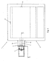
- Fig. 1 illustrates an embodiment of a furnace plant according to the invention.
- the embodiment of the furnace plant shown in Fig. 1 includes a furnace vessel 1.
- the furnace vessel includes side walls 2, a bottom 3 and a roof (not shown).
- molten metal is contained within the interior space of the furnace plant.
- the metal may be heated by at least one heater 10.
- the heater may operate using to a variety of fuels, such as gas and/or electricity.
- the heater heats the metal by radiation and/or convection.
- the heat from the heater maintains molten metal in a liquid state and melts solid metal into a molten state.
- the at least one heater may be arranged in a variety of locations to achieve effective heating of the metal and melting of solid metal.
- the at least one heater could be arranged anywhere around the furnace vessel.
- the at least one heater could be arranged at any of the walls.
- the embodiment shown in Fig. 1 includes two heaters, one arranged at two different walls of the furnace vessel. Other locations that one or more heaters could be arranged include the bottom or roof of the furnace vessel.
- the furnace plant may include as many heaters as necessary.
- the heater may be arranged at any locations about the furnace vessel. For example, a heater could be arranged at two different walls of the furnace vessel, or at the roof and a wall of the furnace vessel, for example.
- a furnace plant according to the invention also includes one or more compartments that extend from the furnace vessel.
- Each compartment includes an interior space that is continuous with the interior space of the furnace plant, such that molten metal may flow between the furnace and the compartment as described below.
- the compartment(s) could be arranged anywhere about the furnace vessel to facilitate operation of the device.
- the compartment(s) could have any desired size.
- the compartment(s) has a small size with respect to the furnace vessel. This can help to concentrate the force on the surface material.
- the invention is particularly useful with aluminum. However, it may be useful in casting other metals, such as lead, copper and zinc. Embodiments of the invention may be utilized with any metal where it is desired to submerge a surface layer during melting of the metal.
- the compartment may be attached to, or be formed as an integral part of a furnace.
- the embodiment of the furnace plant illustrated in Figs. 1 and 2 includes one compartment 4 that extends from the furnace vessel 1.
- the compartment may be mounted on the side of the furnace.
- the compartment includes walls 4a and a bottom 4b.
- the interior surface 4c of the bottom may be at a same horizontal level as the interior surface 3a of the furnace vessel as illustrated in Fig. 2 .
- the walls 4a of the compartment are sufficiently high to contain the molten metal.
- the walls of the compartment may be as high as the walls of the furnace vessel or may be shorter as in the embodiment shown in Figs. 1 and 2 .
- the walls of the compartment may be made or any suitable material. If the furnace is being utilized to melt aluminum, the walls of the compartment may be made of steel. If the invention is utilized with other metals, other materials might be used.
- the walls may be lined with refractory material. Examples of refractory materials that may be utilized can include aluminium oxide based refractory materials or silicium carbide based refractory materials, among others.
- a plate 6 of refractory material or a metal plated clad with refractory material is arranged inside of the compartment. Any suitable material may be utilized in this location. According to one embodiment, the plate may be fixed to the sidewall of the compartment, leaving a clearance in the bottom so the metal can flow.
- the refractory plate 6 may be oriented to achieve a desired mixing of molten metal and/or submerging of material into the molten metal. For example, the height of the refractory plate may be changed as well as the distance of the plate relative to one or more walls of the compartment. Additionally, the tilt of the refractory plate may be altered.
- refractory plate is mounted in the extension compartment in an inclined position such that a gap between a side wall of the compartment is narrower toward a top of the compartment as compared to toward the bottom of the compartment, as in the embodiment illustrated in Figs. 1 and 2 .
- a gap between a side wall of the compartment is narrower toward a top of the compartment as compared to toward the bottom of the compartment, as in the embodiment illustrated in Figs. 1 and 2 .
- The may be a second, larger gap 8 between the refractory plate and the distal side wall of the extension compartment.
- the orientation of the refractory plate may be altered with respect to the distal side wall or the other side walls of the extension compartment.
- the refractory plate is at least 100 mm from the wall of the furnace vessel and at least 50 mm below the level of the top of the bath.
- the refractory plate may be arranged movable or fixed inside the extension compartment. If the refractory plate is movable, the position of the plate may be moved during the operation of the furnace plant. This can help to optimize performance of the furnace plant as conditions change.
- the refractory plate is positioned such that the upper edge of the plate is lower than the meniscus of molten metal inside the compartment. There is a gap between the refractory plate and the bottom of the extension in order to obtain a flow of molten metal from the extension and into the furnace.
- the gaps between the refractory plate and the side walls of the extension compartment that extend from the side wall of the furnace vessel are as small as possible to facilitate flow of the metal within the compartment and between the compartment and the furnace vessel.
- a wall 7 of refractory material is arranged inside the furnace, adjacent to the top part of the refractory plate.
- the refractory wall may be attached in a number of different places.
- the refractory wall could be attached to the walls of the extension compartment, walls of the furnace vessel and/or roof of the furnace vessel.
- the refractory wall typically is arranged such that it will be submerged into the molten metal. Positioned in this manner relative to the compartment, furnace vessel and refractory plate will help to prevent dross from entering the compartment.
- the position and orientation of the refractory wall may be altered to control flow of metal, as the level of molten metal in the furnace plant varies, and/or with changing orientation of the refractory plate.
- One or more electromagnetic stirrers are positioned adjacent to the extension compartment.
- the one or more stirrers may be positioned adjacent one or more walls and/or the bottom of the extension compartment.
- the embodiment shown in Figs. 1 and 2 includes one stirrer 5 arranged adjacent a wall of the extension compartment distal to the furnace vessel.
- a wall of the extension compartment that a stirrer is arranged adjacent may be made of austenitic steel in a furnace plant for melting aluminum.
- a position of the one or more stirrers may be altered.
- the height of any of stirrer arranged adjacent a side wall of the extension compartment may be adjustable.
- the stirrer may be oriented to operate downwards. In such all arrangement, the stirrer may generate a downwardly travelling electromagnetic field into the compartment containing molten metal. The magnetic field moves the molten metal downwards against the bottom of the compartment and further into the furnace.
- the main stirring force achieved by the stirrer, may be imposed in a first area (Area X) behind the refractory plate and below the meniscus of the molten metal held in the compartment.
- a second area (Area Y) is positioned below the meniscus and above the first area (Area X).
- Area Y may be made smaller by repositioning the refractory plate. This can make it possible to accelerate the velocity of molten metal at the meniscus in the compartment. Accelerating the molten metal in turn allows material added at the meniscus to be submerged into the molten metal.
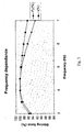
- the stirring force exhibited by the stirrer(s) on the molten metal may vary with the frequency with which the stirrer(s).
- Fig. 3 illustrates a relationship between stirring force and stirring frequency according to one embodiment of the invention.
- Stirring force exhibited on the molten metal may also vary with the width of the opening in the compartment.
- Fig. 4 illustrates a relationship between stirring force and opening width according to one embodiment of the invention.
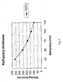
- Stirring force exhibited on the molten metal may also vary with the thickness of the refractory.
- Fig. 5 illustrates a relationship between stirring force and refractory thickness according to one embodiment of the invention.
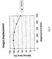
- Stirring force exhibited on the molten metal may also vary with positioning of the stirrer relative to the vertical center of the compartment.
- Fig. 3 illustrates a relationship between stirring force and stirring frequency according to one embodiment of the invention.
- Stirring force exhibited on the molten metal may also vary with the width of the opening in the compartment.
- Fig. 4 illustrates
- the stirrer can generate a maximum velocity of about 2.7 m/s in downward stirring and about 3.2 m/s in upward stirring.
- the stirrer can generate a maximum velocity of about 3.8 m/s in downward stirring.
- the stirrer may impose an upwardly travelling electromagnetic field into the compartment, containing molten metal. This electromagnetic field moves the molten metal upwards against and over the top of the refractory plate and further back into the furnace.
- Embodiments of the invention make it possible to use a common electromagnetic stirrer in order to create a high velocity of molten metal, in the compartment, at the meniscus sufficient to cause metal chips, swarf and other alloy elements to be easily submerged into the bath of molten metal in the compartment.
- a common electromagnetic stirrer in order to create a high velocity of molten metal, in the compartment, at the meniscus sufficient to cause metal chips, swarf and other alloy elements to be easily submerged into the bath of molten metal in the compartment.
- these types of materials do not sink under the meniscus by gravity alone. Rather, they float on the meniscus exposed to the surface environment, which oxidises the materials and causes losses in yield.
Landscapes
- Engineering & Computer Science (AREA)
- Mechanical Engineering (AREA)
- Chemical & Material Sciences (AREA)
- General Engineering & Computer Science (AREA)
- Organic Chemistry (AREA)
- Metallurgy (AREA)
- Materials Engineering (AREA)
- Manufacturing & Machinery (AREA)
- Environmental & Geological Engineering (AREA)
- Geology (AREA)
- General Life Sciences & Earth Sciences (AREA)
- Life Sciences & Earth Sciences (AREA)
- Waste-Gas Treatment And Other Accessory Devices For Furnaces (AREA)
- Vertical, Hearth, Or Arc Furnaces (AREA)
- Mixers Of The Rotary Stirring Type (AREA)
- Physical Or Chemical Processes And Apparatus (AREA)
Claims (21)
- Ofenanlage, umfassend:mindestens ein Ofengefäß (1) mit Seitenwände (4a), einem Boden (4b) und einem Dach;mindestens eine Heizvorrichtung, konfiguriert, um Metall im Ofengefäß zu erhitzen;ein Abteil (4) mit Seitenwände, die mit einem feuerfesten Material ausgekleidet sind, wobei das Abteil (4) eine Erweiterung des Ofengefäßes bildet;mindestens einen elektromagnetischen Rührer, der außerhalb vom und benachbart zum Ofengefäß angeordnet ist; undeine feuerfeste Wand (7), die teilweise in das Flüssigmetall eingetaucht ist und benachbart zur Oberkante der feuerfesten Platte (6) ist, um auf der Oberfläche des Flüssigmetalls schwimmende Schlacke zurückzuhalten;und gekennzeichnet durch:eine feuerfeste Platte (6), die im Inneren des Abteils angeordnet ist, wobei die feuerfeste Platte eine Oberkante aufweist, die konfiguriert ist, um unter einem Meniskus des Flüssigmetalls zu liegen, und eine Unterkante, die von einem Boden des Abteils beabstandet ist, wobei die feuerfeste Platte (6) derart angeordnet ist, dass ein Zwischenraum zwischen der feuerfesten Platte (6) und einer Seitenwand (4a) des Abteils (4) zum Boden des Abteils (4) hin zunimmt.
- Ofenanlage nach Anspruch 1, wobei die feuerfeste Platte (6) beweglich ist.
- Ofenanlage nach Anspruch 1, wobei die feuerfeste Platte (6) feststehend ist.
- Ofenanlage nach Anspruch 1, wobei:die feuerfeste Wand (7) am Dach des Ofengefäßes (1) angebracht ist und innerhalb des Ofengefäßes (1) angeordnet ist.
- Ofenanlage nach Anspruch 1, wobei der mindestens eine elektromagnetische Rührer (5) vertikal und in naher Nähe der Seitenwand (4a) des Abteils (4) angeordnet ist.
- Ofenanlage nach Anspruch 5, wobei eine Höhe des elektromagnetischen Rührers (5) verstellbar ist.
- Ofenanlage nach Anspruch 1, wobei der mindestens eine elektromagnetische Rührer (5) unter und in naher Nähe des Bodens des Ofengefäßes (1) angeordnet ist, um durch den Boden hindurch zu wirken und auf das im Ofengefäß vorhandene Flüssigmetall ein Rührfeld anzulegen.
- Ofenanlage nach Anspruch 1, wobei die Seitenwände des Abteils Stahlplatten umfassen.
- Ofenanlage nach Anspruch 1, wobei die Seitenwand (4a) des Abteils, die benachbart zum Rührer (5) ist, in einem Abstand vom Ofengefäß (1) angeordnet ist.
- Ofenanlage nach Anspruch 1, wobei der mindestens eine Rührer (5) Austenitstahl umfasst.
- Ofenanlage nach Anspruch 1, wobei die Seitenwand (4a) des Abteils benachbart zum Rührer (5) ist.
- Verfahren zum Eintauchen von Material in Flüssigmetall, wobei das Verfahren umfasst:das Zuführen von festen Metallteilen in ein Schmelzbad aus Flüssigmetall in einem Abteil (4), das Seitenwände (4a) aufweist, wobei das Abteil eine Erweiterung des Ofengefäßes (1) bildet, wobei im Abteil (4) eine feuerfeste Platte (6) angeordnet ist, wobei die feuerfeste Platte (6) derart angeordnet ist, dass ein Zwischenraum (8, 9) zwischen der Platte und einer der Seitenwände (4a) des Abteils zum Boden des Abteils (4) hin zunimmt, und die feuerfeste Platte (6) eine Oberkante aufweist, die konfiguriert ist, um unter einem Meniskus des Flüssigmetalls zu liegen, und eine Unterkante, die von einem Boden des Abteils (4) beabstandet ist, und wobei eine teilweise in das Flüssigmetall eingetauchte feuerfeste Wand (7), die benachbart zur Oberkante der feuerfesten Platte im Inneren des Ofengefäßes (1) angeordnet ist, am Dach des Ofengefäßes (1) angebracht ist; und das Anlegen einer elektromagnetischen Kraft an das Flüssigaluminium im Abteil (4) durch ein Magnetfeld, das von einem elektromagnetischen Rührer (5) erzeugt wird, der in naher Nähe der Seitenwände oder nahe dem Boden des Abteils (4) installiert ist.
- Verfahren nach Anspruch 12, außerdem umfassend: das Bewegen der feuerfesten Platte (6).
- Verfahren nach Anspruch 12, außerdem umfassend: das Halten der feuerfesten Platte (6) in einer festen Position.
- Verfahren nach Anspruch 12, außerdem umfassend: das Anordnen einer teilweise in das Flüssigmetall eingetauchten feuerfesten Wand (7) im Inneren des Ofengefäßes benachbart zur Oberkante der feuerfesten Platte (6).
- Verfahren nach Anspruch 15, wobei die feuerfeste Wand angeordnet wird, um den Eintritt von Schlacke in das Abteil (4) zu verhindern.
- Verfahren nach Anspruch 12, wobei der mindestens eine elektromagnetische Rührer (5) vertikal und in naher Nähe der Seitenwand (4a) des Abteils (4) angeordnet ist.
- Verfahren nach Anspruch 17, außerdem umfassend: das Verstellen einer Höhe des elektromagnetischen Rührers (5).
- Verfahren nach Anspruch 12, wobei der mindestens eine elektromagnetische Rührer (5) unter und in der Nähe des Bodens des Ofengefäßes (1) angeordnet ist, um durch den Boden hindurch zu wirken und auf das im Ofengefäß vorhandene Flüssigmetall ein Rührfeld anzulegen.
- Verfahren nach Anspruch 12, wobei die Wand des Abteils (4), die benachbart zum Rührer (5) ist, in einem Abstand vom Ofengefäß (1) angeordnet ist.
- Verfahren nach Anspruch 12, wobei die Wand des Abteils (4) benachbart zum Rührer (5) ist.
Applications Claiming Priority (2)
| Application Number | Priority Date | Filing Date | Title |
|---|---|---|---|
| US96066807P | 2007-10-09 | 2007-10-09 | |
| PCT/IB2008/002673 WO2009047624A1 (en) | 2007-10-09 | 2008-10-09 | Device for submerging material into liquid metal by an electromagnetic stirrer |
Publications (3)
| Publication Number | Publication Date |
|---|---|
| EP2198228A1 EP2198228A1 (de) | 2010-06-23 |
| EP2198228B1 true EP2198228B1 (de) | 2012-02-22 |
| EP2198228B8 EP2198228B8 (de) | 2012-10-24 |
Family
ID=40242716
Family Applications (1)
| Application Number | Title | Priority Date | Filing Date |
|---|---|---|---|
| EP08807219A Not-in-force EP2198228B8 (de) | 2007-10-09 | 2008-10-09 | Vorrichtung zum eintauchen von material in flüssigmetall mit einem elektromechanischen rührer |
Country Status (6)
| Country | Link |
|---|---|
| US (1) | US8043403B2 (de) |
| EP (1) | EP2198228B8 (de) |
| KR (1) | KR101461260B1 (de) |
| CN (1) | CN101821574B (de) |
| AT (1) | ATE546555T1 (de) |
| WO (1) | WO2009047624A1 (de) |
Families Citing this family (4)
| Publication number | Priority date | Publication date | Assignee | Title |
|---|---|---|---|---|
| JP5766572B2 (ja) * | 2011-09-30 | 2015-08-19 | 高橋 謙三 | 金属溶解炉用渦室体及びそれを用いた金属溶解炉 |
| JP5795296B2 (ja) * | 2012-09-27 | 2015-10-14 | 高橋 謙三 | 金属溶解炉用渦室体及びそれを用いた金属溶解炉 |
| GB2536185A (en) * | 2014-08-08 | 2016-09-14 | Fives Solios Ltd | Method and apparatus for submerging materials into a molten material bath |
| CN107630145A (zh) * | 2017-09-20 | 2018-01-26 | 李益隆 | 介质发热熔铝的方法 |
Family Cites Families (7)
| Publication number | Priority date | Publication date | Assignee | Title |
|---|---|---|---|---|
| CA1226738A (en) * | 1983-03-14 | 1987-09-15 | Robert J. Ormesher | Metal scrap reclamation system |
| CA1330486C (en) * | 1988-05-20 | 1994-07-05 | Marc-Andre Thibault | Apparatus for stirring molten metal |
| JP3299332B2 (ja) | 1992-04-24 | 2002-07-08 | 株式会社宮本工業所 | アルミニウム合金の廃材溶解装置 |
| US5391348A (en) * | 1994-01-11 | 1995-02-21 | Magneco/Metrel, Inc. | Apparatus and method for making steel alloys in a tundish |
| SE504400C2 (sv) * | 1995-04-25 | 1997-02-03 | Asea Brown Boveri | Ugnsanläggning för smältning av metall och/eller varmhållning av smält metall |
| FR2815642B1 (fr) * | 2000-10-20 | 2003-07-11 | Pechiney Rhenalu | Dispositif rotatif de dispersion de gaz pour le traitement d'un bain de metal liquide |
| KR20140014588A (ko) * | 2012-07-25 | 2014-02-06 | 주식회사 큐빅스 | 고효율 알루미늄 전기용해로 제어장치 |
-
2008
- 2008-10-09 CN CN2008801107009A patent/CN101821574B/zh not_active Expired - Fee Related
- 2008-10-09 WO PCT/IB2008/002673 patent/WO2009047624A1/en not_active Ceased
- 2008-10-09 EP EP08807219A patent/EP2198228B8/de not_active Not-in-force
- 2008-10-09 KR KR1020107007596A patent/KR101461260B1/ko not_active Expired - Fee Related
- 2008-10-09 AT AT08807219T patent/ATE546555T1/de active
- 2008-10-09 US US12/682,355 patent/US8043403B2/en not_active Expired - Fee Related
Also Published As
| Publication number | Publication date |
|---|---|
| EP2198228A1 (de) | 2010-06-23 |
| CN101821574A (zh) | 2010-09-01 |
| ATE546555T1 (de) | 2012-03-15 |
| CN101821574B (zh) | 2012-07-04 |
| EP2198228B8 (de) | 2012-10-24 |
| KR101461260B1 (ko) | 2014-11-12 |
| US8043403B2 (en) | 2011-10-25 |
| US20100236362A1 (en) | 2010-09-23 |
| WO2009047624A1 (en) | 2009-04-16 |
| KR20100072016A (ko) | 2010-06-29 |
Similar Documents
| Publication | Publication Date | Title |
|---|---|---|
| EP2198228B1 (de) | Vorrichtung zum eintauchen von material in flüssigmetall mit einem elektromechanischen rührer | |
| EP0017150B1 (de) | Vorrichtung zum Raffinieren geschmolzenen Aluminiums | |
| JP6465854B2 (ja) | 金属流インパクトパッド及びタンディッシュ用ディフューザー | |
| EP1514065B1 (de) | Elektromagnetisches induktionsgerät und verfahren zur behandlung geschmolzener werkstoffe | |
| US9360255B2 (en) | Method and arrangement for vortex reduction in a metal making process | |
| JP6230847B2 (ja) | アルミ溶解保持炉 | |
| ZA200410141B (en) | Electromagnetic induction apparatus and method of treatment of molten materials | |
| US3626072A (en) | Method and a device for continuous slagging of electric and reverberatory furnaces, operating with a deep slag basin | |
| US10739074B2 (en) | Metallurgical apparatus | |
| US4375885A (en) | Reverberatory furnace | |
| JP2020139662A (ja) | アーク式電気炉、アーク式電気炉における排滓方法及び溶融金属の製造方法 | |
| JP2020139661A (ja) | アーク式電気炉、アーク式電気炉における排滓方法及び溶融金属の製造方法 | |
| KR101104798B1 (ko) | 용강 제어 장치 | |
| KR20180040587A (ko) | 채널형 유도로 | |
| WO2001061059A1 (en) | A continuously operating method for producing refined metal | |
| JP2003025048A (ja) | 鋼の連続鋳造方法 | |
| Vukovic et al. | A gas purging system for copper and aluminum furnaces | |
| SU349727A1 (ru) | Устройство для факельно-шлакового переплава | |
| SU1196401A1 (ru) | Способ рафинирования сплавов, содержащих легкоплавкие компоненты | |
| JPH08327249A (ja) | 鋼スクラップ溶解炉 | |
| JPH08197207A (ja) | 開閉可能な堰を備えたタンディッシュ | |
| GB2536185A (en) | Method and apparatus for submerging materials into a molten material bath | |
| UA75536C2 (en) | A method for metallurgical processing iron-containing material and a mechanism for realizing the same |
Legal Events
| Date | Code | Title | Description |
|---|---|---|---|
| PUAI | Public reference made under article 153(3) epc to a published international application that has entered the european phase |
Free format text: ORIGINAL CODE: 0009012 |
|
| 17P | Request for examination filed |
Effective date: 20100510 |
|
| AK | Designated contracting states |
Kind code of ref document: A1 Designated state(s): AT BE BG CH CY CZ DE DK EE ES FI FR GB GR HR HU IE IS IT LI LT LU LV MC MT NL NO PL PT RO SE SI SK TR |
|
| AX | Request for extension of the european patent |
Extension state: AL BA MK RS |
|
| RIN1 | Information on inventor provided before grant (corrected) |
Inventor name: RYDHOLM, BENGT Inventor name: SVENSSON, ERIK Inventor name: HACKL, HELMUT Inventor name: LUNDSTROM, ALF Inventor name: SJODEN, OLOF Inventor name: ERIKSSON, JAN-ERIK Inventor name: KROON, TORD Inventor name: LINDBLAD, TORD |
|
| DAX | Request for extension of the european patent (deleted) | ||
| GRAP | Despatch of communication of intention to grant a patent |
Free format text: ORIGINAL CODE: EPIDOSNIGR1 |
|
| REG | Reference to a national code |
Ref country code: DE Ref legal event code: R079 Ref document number: 602008013643 Country of ref document: DE Free format text: PREVIOUS MAIN CLASS: F27B0003040000 Ipc: C22B0007000000 |
|
| GRAC | Information related to communication of intention to grant a patent modified |
Free format text: ORIGINAL CODE: EPIDOSCIGR1 |
|
| RIC1 | Information provided on ipc code assigned before grant |
Ipc: C22B 21/00 20060101ALI20111130BHEP Ipc: F27B 3/04 20060101ALI20111130BHEP Ipc: F27D 27/00 20100101ALI20111130BHEP Ipc: C22B 7/00 20060101AFI20111130BHEP Ipc: F27D 3/00 20060101ALI20111130BHEP |
|
| GRAS | Grant fee paid |
Free format text: ORIGINAL CODE: EPIDOSNIGR3 |
|
| GRAA | (expected) grant |
Free format text: ORIGINAL CODE: 0009210 |
|
| AK | Designated contracting states |
Kind code of ref document: B1 Designated state(s): AT BE BG CH CY CZ DE DK EE ES FI FR GB GR HR HU IE IS IT LI LT LU LV MC MT NL NO PL PT RO SE SI SK TR |
|
| REG | Reference to a national code |
Ref country code: GB Ref legal event code: FG4D |
|
| REG | Reference to a national code |
Ref country code: CH Ref legal event code: EP |
|
| REG | Reference to a national code |
Ref country code: AT Ref legal event code: REF Ref document number: 546555 Country of ref document: AT Kind code of ref document: T Effective date: 20120315 |
|
| REG | Reference to a national code |
Ref country code: IE Ref legal event code: FG4D |
|
| REG | Reference to a national code |
Ref country code: DE Ref legal event code: R096 Ref document number: 602008013643 Country of ref document: DE Effective date: 20120419 |
|
| REG | Reference to a national code |
Ref country code: NL Ref legal event code: VDEP Effective date: 20120222 |
|
| LTIE | Lt: invalidation of european patent or patent extension |
Effective date: 20120222 |
|
| PG25 | Lapsed in a contracting state [announced via postgrant information from national office to epo] |
Ref country code: IS Free format text: LAPSE BECAUSE OF FAILURE TO SUBMIT A TRANSLATION OF THE DESCRIPTION OR TO PAY THE FEE WITHIN THE PRESCRIBED TIME-LIMIT Effective date: 20120622 Ref country code: NO Free format text: LAPSE BECAUSE OF FAILURE TO SUBMIT A TRANSLATION OF THE DESCRIPTION OR TO PAY THE FEE WITHIN THE PRESCRIBED TIME-LIMIT Effective date: 20120522 Ref country code: LT Free format text: LAPSE BECAUSE OF FAILURE TO SUBMIT A TRANSLATION OF THE DESCRIPTION OR TO PAY THE FEE WITHIN THE PRESCRIBED TIME-LIMIT Effective date: 20120222 Ref country code: NL Free format text: LAPSE BECAUSE OF FAILURE TO SUBMIT A TRANSLATION OF THE DESCRIPTION OR TO PAY THE FEE WITHIN THE PRESCRIBED TIME-LIMIT Effective date: 20120222 Ref country code: HR Free format text: LAPSE BECAUSE OF FAILURE TO SUBMIT A TRANSLATION OF THE DESCRIPTION OR TO PAY THE FEE WITHIN THE PRESCRIBED TIME-LIMIT Effective date: 20120222 |
|
| PG25 | Lapsed in a contracting state [announced via postgrant information from national office to epo] |
Ref country code: FI Free format text: LAPSE BECAUSE OF FAILURE TO SUBMIT A TRANSLATION OF THE DESCRIPTION OR TO PAY THE FEE WITHIN THE PRESCRIBED TIME-LIMIT Effective date: 20120222 Ref country code: BE Free format text: LAPSE BECAUSE OF FAILURE TO SUBMIT A TRANSLATION OF THE DESCRIPTION OR TO PAY THE FEE WITHIN THE PRESCRIBED TIME-LIMIT Effective date: 20120222 Ref country code: LV Free format text: LAPSE BECAUSE OF FAILURE TO SUBMIT A TRANSLATION OF THE DESCRIPTION OR TO PAY THE FEE WITHIN THE PRESCRIBED TIME-LIMIT Effective date: 20120222 Ref country code: PT Free format text: LAPSE BECAUSE OF FAILURE TO SUBMIT A TRANSLATION OF THE DESCRIPTION OR TO PAY THE FEE WITHIN THE PRESCRIBED TIME-LIMIT Effective date: 20120622 Ref country code: GR Free format text: LAPSE BECAUSE OF FAILURE TO SUBMIT A TRANSLATION OF THE DESCRIPTION OR TO PAY THE FEE WITHIN THE PRESCRIBED TIME-LIMIT Effective date: 20120523 |
|
| PG25 | Lapsed in a contracting state [announced via postgrant information from national office to epo] |
Ref country code: CY Free format text: LAPSE BECAUSE OF FAILURE TO SUBMIT A TRANSLATION OF THE DESCRIPTION OR TO PAY THE FEE WITHIN THE PRESCRIBED TIME-LIMIT Effective date: 20120222 |
|
| RAP2 | Party data changed (patent owner data changed or rights of a patent transferred) |
Owner name: ABB AB |
|
| PG25 | Lapsed in a contracting state [announced via postgrant information from national office to epo] |
Ref country code: SI Free format text: LAPSE BECAUSE OF FAILURE TO SUBMIT A TRANSLATION OF THE DESCRIPTION OR TO PAY THE FEE WITHIN THE PRESCRIBED TIME-LIMIT Effective date: 20120222 Ref country code: PL Free format text: LAPSE BECAUSE OF FAILURE TO SUBMIT A TRANSLATION OF THE DESCRIPTION OR TO PAY THE FEE WITHIN THE PRESCRIBED TIME-LIMIT Effective date: 20120222 Ref country code: SE Free format text: LAPSE BECAUSE OF FAILURE TO SUBMIT A TRANSLATION OF THE DESCRIPTION OR TO PAY THE FEE WITHIN THE PRESCRIBED TIME-LIMIT Effective date: 20120222 Ref country code: EE Free format text: LAPSE BECAUSE OF FAILURE TO SUBMIT A TRANSLATION OF THE DESCRIPTION OR TO PAY THE FEE WITHIN THE PRESCRIBED TIME-LIMIT Effective date: 20120222 Ref country code: RO Free format text: LAPSE BECAUSE OF FAILURE TO SUBMIT A TRANSLATION OF THE DESCRIPTION OR TO PAY THE FEE WITHIN THE PRESCRIBED TIME-LIMIT Effective date: 20120222 Ref country code: DK Free format text: LAPSE BECAUSE OF FAILURE TO SUBMIT A TRANSLATION OF THE DESCRIPTION OR TO PAY THE FEE WITHIN THE PRESCRIBED TIME-LIMIT Effective date: 20120222 Ref country code: CZ Free format text: LAPSE BECAUSE OF FAILURE TO SUBMIT A TRANSLATION OF THE DESCRIPTION OR TO PAY THE FEE WITHIN THE PRESCRIBED TIME-LIMIT Effective date: 20120222 |
|
| REG | Reference to a national code |
Ref country code: SE Ref legal event code: RINS Effective date: 20121109 |
|
| PG25 | Lapsed in a contracting state [announced via postgrant information from national office to epo] |
Ref country code: SK Free format text: LAPSE BECAUSE OF FAILURE TO SUBMIT A TRANSLATION OF THE DESCRIPTION OR TO PAY THE FEE WITHIN THE PRESCRIBED TIME-LIMIT Effective date: 20120222 Ref country code: IT Free format text: LAPSE BECAUSE OF FAILURE TO SUBMIT A TRANSLATION OF THE DESCRIPTION OR TO PAY THE FEE WITHIN THE PRESCRIBED TIME-LIMIT Effective date: 20120222 |
|
| REG | Reference to a national code |
Ref country code: SE Ref legal event code: TRGR |
|
| REG | Reference to a national code |
Ref country code: AT Ref legal event code: NFJG Ref document number: 546555 Country of ref document: AT Kind code of ref document: T Effective date: 20121016 |
|
| REG | Reference to a national code |
Ref country code: NO Ref legal event code: MMEP |
|
| PLBE | No opposition filed within time limit |
Free format text: ORIGINAL CODE: 0009261 |
|
| STAA | Information on the status of an ep patent application or granted ep patent |
Free format text: STATUS: NO OPPOSITION FILED WITHIN TIME LIMIT |
|
| 26N | No opposition filed |
Effective date: 20121123 |
|
| PGRI | Patent reinstated in contracting state [announced from national office to epo] |
Ref country code: IT Effective date: 20121101 |
|
| REG | Reference to a national code |
Ref country code: DE Ref legal event code: R097 Ref document number: 602008013643 Country of ref document: DE Effective date: 20121123 |
|
| REG | Reference to a national code |
Ref country code: AT Ref legal event code: HC Ref document number: 546555 Country of ref document: AT Kind code of ref document: T Owner name: ABB AB, SE Effective date: 20130219 |
|
| PG25 | Lapsed in a contracting state [announced via postgrant information from national office to epo] |
Ref country code: ES Free format text: LAPSE BECAUSE OF FAILURE TO SUBMIT A TRANSLATION OF THE DESCRIPTION OR TO PAY THE FEE WITHIN THE PRESCRIBED TIME-LIMIT Effective date: 20120602 |
|
| PG25 | Lapsed in a contracting state [announced via postgrant information from national office to epo] |
Ref country code: MC Free format text: LAPSE BECAUSE OF NON-PAYMENT OF DUE FEES Effective date: 20121031 |
|
| REG | Reference to a national code |
Ref country code: CH Ref legal event code: PL |
|
| REG | Reference to a national code |
Ref country code: IE Ref legal event code: MM4A |
|
| REG | Reference to a national code |
Ref country code: NO Ref legal event code: T2 Effective date: 20120222 |
|
| PG25 | Lapsed in a contracting state [announced via postgrant information from national office to epo] |
Ref country code: IE Free format text: LAPSE BECAUSE OF NON-PAYMENT OF DUE FEES Effective date: 20121009 Ref country code: CH Free format text: LAPSE BECAUSE OF NON-PAYMENT OF DUE FEES Effective date: 20121031 Ref country code: BG Free format text: LAPSE BECAUSE OF FAILURE TO SUBMIT A TRANSLATION OF THE DESCRIPTION OR TO PAY THE FEE WITHIN THE PRESCRIBED TIME-LIMIT Effective date: 20120522 Ref country code: LI Free format text: LAPSE BECAUSE OF NON-PAYMENT OF DUE FEES Effective date: 20121031 |
|
| PGRI | Patent reinstated in contracting state [announced from national office to epo] |
Ref country code: NO Effective date: 20130605 |
|
| PG25 | Lapsed in a contracting state [announced via postgrant information from national office to epo] |
Ref country code: MT Free format text: LAPSE BECAUSE OF FAILURE TO SUBMIT A TRANSLATION OF THE DESCRIPTION OR TO PAY THE FEE WITHIN THE PRESCRIBED TIME-LIMIT Effective date: 20120222 |
|
| PG25 | Lapsed in a contracting state [announced via postgrant information from national office to epo] |
Ref country code: TR Free format text: LAPSE BECAUSE OF FAILURE TO SUBMIT A TRANSLATION OF THE DESCRIPTION OR TO PAY THE FEE WITHIN THE PRESCRIBED TIME-LIMIT Effective date: 20120222 |
|
| PG25 | Lapsed in a contracting state [announced via postgrant information from national office to epo] |
Ref country code: LU Free format text: LAPSE BECAUSE OF NON-PAYMENT OF DUE FEES Effective date: 20121009 |
|
| PGRI | Patent reinstated in contracting state [announced from national office to epo] |
Ref country code: SE Effective date: 20121109 |
|
| PG25 | Lapsed in a contracting state [announced via postgrant information from national office to epo] |
Ref country code: HU Free format text: LAPSE BECAUSE OF FAILURE TO SUBMIT A TRANSLATION OF THE DESCRIPTION OR TO PAY THE FEE WITHIN THE PRESCRIBED TIME-LIMIT Effective date: 20081009 |
|
| REG | Reference to a national code |
Ref country code: FR Ref legal event code: PLFP Year of fee payment: 8 |
|
| PG25 | Lapsed in a contracting state [announced via postgrant information from national office to epo] |
Ref country code: IT Free format text: LAPSE BECAUSE OF FAILURE TO SUBMIT A TRANSLATION OF THE DESCRIPTION OR TO PAY THE FEE WITHIN THE PRESCRIBED TIME-LIMIT Effective date: 20151009 |
|
| REG | Reference to a national code |
Ref country code: FR Ref legal event code: PLFP Year of fee payment: 9 |
|
| PG25 | Lapsed in a contracting state [announced via postgrant information from national office to epo] |
Ref country code: IT Free format text: LAPSE BECAUSE OF FAILURE TO SUBMIT A TRANSLATION OF THE DESCRIPTION OR TO PAY THE FEE WITHIN THE PRESCRIBED TIME-LIMIT Effective date: 20151009 |
|
| PGFP | Annual fee paid to national office [announced via postgrant information from national office to epo] |
Ref country code: DE Payment date: 20161020 Year of fee payment: 9 Ref country code: GB Payment date: 20161020 Year of fee payment: 9 Ref country code: FR Payment date: 20161020 Year of fee payment: 9 Ref country code: NO Payment date: 20161024 Year of fee payment: 9 |
|
| PGRI | Patent reinstated in contracting state [announced from national office to epo] |
Ref country code: IT Effective date: 20161125 |
|
| PGFP | Annual fee paid to national office [announced via postgrant information from national office to epo] |
Ref country code: IT Payment date: 20161024 Year of fee payment: 9 Ref country code: AT Payment date: 20161020 Year of fee payment: 9 Ref country code: SE Payment date: 20161019 Year of fee payment: 9 |
|
| REG | Reference to a national code |
Ref country code: DE Ref legal event code: R119 Ref document number: 602008013643 Country of ref document: DE |
|
| REG | Reference to a national code |
Ref country code: NO Ref legal event code: MMEP |
|
| REG | Reference to a national code |
Ref country code: SE Ref legal event code: EUG |
|
| REG | Reference to a national code |
Ref country code: AT Ref legal event code: MM01 Ref document number: 546555 Country of ref document: AT Kind code of ref document: T Effective date: 20171009 |
|
| GBPC | Gb: european patent ceased through non-payment of renewal fee |
Effective date: 20171009 |
|
| REG | Reference to a national code |
Ref country code: FR Ref legal event code: ST Effective date: 20180629 |
|
| PG25 | Lapsed in a contracting state [announced via postgrant information from national office to epo] |
Ref country code: NO Free format text: LAPSE BECAUSE OF FAILURE TO SUBMIT A TRANSLATION OF THE DESCRIPTION OR TO PAY THE FEE WITHIN THE PRESCRIBED TIME-LIMIT Effective date: 20171031 Ref country code: GB Free format text: LAPSE BECAUSE OF NON-PAYMENT OF DUE FEES Effective date: 20171009 Ref country code: DE Free format text: LAPSE BECAUSE OF NON-PAYMENT OF DUE FEES Effective date: 20180501 |
|
| PG25 | Lapsed in a contracting state [announced via postgrant information from national office to epo] |
Ref country code: SE Free format text: LAPSE BECAUSE OF FAILURE TO SUBMIT A TRANSLATION OF THE DESCRIPTION OR TO PAY THE FEE WITHIN THE PRESCRIBED TIME-LIMIT Effective date: 20171010 Ref country code: FR Free format text: LAPSE BECAUSE OF NON-PAYMENT OF DUE FEES Effective date: 20171031 Ref country code: AT Free format text: LAPSE BECAUSE OF NON-PAYMENT OF DUE FEES Effective date: 20171009 |
|
| PG25 | Lapsed in a contracting state [announced via postgrant information from national office to epo] |
Ref country code: IT Free format text: LAPSE BECAUSE OF FAILURE TO SUBMIT A TRANSLATION OF THE DESCRIPTION OR TO PAY THE FEE WITHIN THE PRESCRIBED TIME-LIMIT Effective date: 20171009 |