US8043403B2 - Device for submerging material into liquid metal by an electromagnetic stirrer - Google Patents
Device for submerging material into liquid metal by an electromagnetic stirrer Download PDFInfo
- Publication number
- US8043403B2 US8043403B2 US12/682,355 US68235508A US8043403B2 US 8043403 B2 US8043403 B2 US 8043403B2 US 68235508 A US68235508 A US 68235508A US 8043403 B2 US8043403 B2 US 8043403B2
- Authority
- US
- United States
- Prior art keywords
- compartment
- furnace
- refractory
- stirrer
- plate
- Prior art date
- Legal status (The legal status is an assumption and is not a legal conclusion. Google has not performed a legal analysis and makes no representation as to the accuracy of the status listed.)
- Expired - Fee Related, expires
Links
- 239000000463 material Substances 0.000 title claims description 17
- 229910001338 liquidmetal Inorganic materials 0.000 title claims description 6
- 229910052751 metal Inorganic materials 0.000 claims abstract description 73
- 239000002184 metal Substances 0.000 claims abstract description 73
- 230000005499 meniscus Effects 0.000 claims abstract description 11
- 239000011819 refractory material Substances 0.000 claims abstract description 10
- 238000000034 method Methods 0.000 claims description 14
- 239000007787 solid Substances 0.000 claims description 6
- 229910000831 Steel Inorganic materials 0.000 claims description 4
- 239000010959 steel Substances 0.000 claims description 4
- 239000000155 melt Substances 0.000 claims description 3
- 238000003756 stirring Methods 0.000 description 20
- 238000002844 melting Methods 0.000 description 7
- 230000008018 melting Effects 0.000 description 7
- 229910052782 aluminium Inorganic materials 0.000 description 5
- XAGFODPZIPBFFR-UHFFFAOYSA-N aluminium Chemical compound [Al] XAGFODPZIPBFFR-UHFFFAOYSA-N 0.000 description 5
- 238000005266 casting Methods 0.000 description 4
- PNEYBMLMFCGWSK-UHFFFAOYSA-N Alumina Chemical compound [O-2].[O-2].[O-2].[Al+3].[Al+3] PNEYBMLMFCGWSK-UHFFFAOYSA-N 0.000 description 3
- 230000005672 electromagnetic field Effects 0.000 description 3
- 150000002739 metals Chemical class 0.000 description 3
- 229910045601 alloy Inorganic materials 0.000 description 2
- 239000000956 alloy Substances 0.000 description 2
- 238000006073 displacement reaction Methods 0.000 description 2
- 239000007788 liquid Substances 0.000 description 2
- RYGMFSIKBFXOCR-UHFFFAOYSA-N Copper Chemical compound [Cu] RYGMFSIKBFXOCR-UHFFFAOYSA-N 0.000 description 1
- XUIMIQQOPSSXEZ-UHFFFAOYSA-N Silicon Chemical compound [Si] XUIMIQQOPSSXEZ-UHFFFAOYSA-N 0.000 description 1
- HCHKCACWOHOZIP-UHFFFAOYSA-N Zinc Chemical compound [Zn] HCHKCACWOHOZIP-UHFFFAOYSA-N 0.000 description 1
- 230000001133 acceleration Effects 0.000 description 1
- 239000004411 aluminium Substances 0.000 description 1
- 230000015572 biosynthetic process Effects 0.000 description 1
- 239000012141 concentrate Substances 0.000 description 1
- 239000000356 contaminant Substances 0.000 description 1
- 229910052802 copper Inorganic materials 0.000 description 1
- 239000010949 copper Substances 0.000 description 1
- 230000000694 effects Effects 0.000 description 1
- 230000005611 electricity Effects 0.000 description 1
- 239000000446 fuel Substances 0.000 description 1
- 230000005484 gravity Effects 0.000 description 1
- 238000010438 heat treatment Methods 0.000 description 1
- 239000011133 lead Substances 0.000 description 1
- 239000000203 mixture Substances 0.000 description 1
- 230000003647 oxidation Effects 0.000 description 1
- 238000007254 oxidation reaction Methods 0.000 description 1
- 230000005855 radiation Effects 0.000 description 1
- 239000002344 surface layer Substances 0.000 description 1
- 230000003313 weakening effect Effects 0.000 description 1
- 239000011701 zinc Substances 0.000 description 1
- 229910052725 zinc Inorganic materials 0.000 description 1
Images


Classifications
-
- F—MECHANICAL ENGINEERING; LIGHTING; HEATING; WEAPONS; BLASTING
- F27—FURNACES; KILNS; OVENS; RETORTS
- F27B—FURNACES, KILNS, OVENS OR RETORTS IN GENERAL; OPEN SINTERING OR LIKE APPARATUS
- F27B3/00—Hearth-type furnaces, e.g. of reverberatory type; Electric arc furnaces ; Tank furnaces
- F27B3/04—Hearth-type furnaces, e.g. of reverberatory type; Electric arc furnaces ; Tank furnaces of multiple-hearth type; of multiple-chamber type; Combinations of hearth-type furnaces
- F27B3/045—Multiple chambers, e.g. one of which is used for charging
-
- C—CHEMISTRY; METALLURGY
- C22—METALLURGY; FERROUS OR NON-FERROUS ALLOYS; TREATMENT OF ALLOYS OR NON-FERROUS METALS
- C22B—PRODUCTION AND REFINING OF METALS; PRETREATMENT OF RAW MATERIALS
- C22B21/00—Obtaining aluminium
- C22B21/0084—Obtaining aluminium melting and handling molten aluminium
- C22B21/0092—Remelting scrap, skimmings or any secondary source aluminium
-
- C—CHEMISTRY; METALLURGY
- C22—METALLURGY; FERROUS OR NON-FERROUS ALLOYS; TREATMENT OF ALLOYS OR NON-FERROUS METALS
- C22B—PRODUCTION AND REFINING OF METALS; PRETREATMENT OF RAW MATERIALS
- C22B7/00—Working up raw materials other than ores, e.g. scrap, to produce non-ferrous metals and compounds thereof; Methods of a general interest or applied to the winning of more than two metals
- C22B7/001—Dry processes
- C22B7/003—Dry processes only remelting, e.g. of chips, borings, turnings; apparatus used therefor
-
- F—MECHANICAL ENGINEERING; LIGHTING; HEATING; WEAPONS; BLASTING
- F27—FURNACES; KILNS; OVENS; RETORTS
- F27D—DETAILS OR ACCESSORIES OF FURNACES, KILNS, OVENS OR RETORTS, IN SO FAR AS THEY ARE OF KINDS OCCURRING IN MORE THAN ONE KIND OF FURNACE
- F27D27/00—Stirring devices for molten material
-
- F—MECHANICAL ENGINEERING; LIGHTING; HEATING; WEAPONS; BLASTING
- F27—FURNACES; KILNS; OVENS; RETORTS
- F27D—DETAILS OR ACCESSORIES OF FURNACES, KILNS, OVENS OR RETORTS, IN SO FAR AS THEY ARE OF KINDS OCCURRING IN MORE THAN ONE KIND OF FURNACE
- F27D3/00—Charging; Discharging; Manipulation of charge
- F27D3/0033—Charging; Discharging; Manipulation of charge charging of particulate material
-
- C—CHEMISTRY; METALLURGY
- C22—METALLURGY; FERROUS OR NON-FERROUS ALLOYS; TREATMENT OF ALLOYS OR NON-FERROUS METALS
- C22B—PRODUCTION AND REFINING OF METALS; PRETREATMENT OF RAW MATERIALS
- C22B9/00—General processes of refining or remelting of metals; Apparatus for electroslag or arc remelting of metals
- C22B9/003—General processes of refining or remelting of metals; Apparatus for electroslag or arc remelting of metals by induction
-
- Y—GENERAL TAGGING OF NEW TECHNOLOGICAL DEVELOPMENTS; GENERAL TAGGING OF CROSS-SECTIONAL TECHNOLOGIES SPANNING OVER SEVERAL SECTIONS OF THE IPC; TECHNICAL SUBJECTS COVERED BY FORMER USPC CROSS-REFERENCE ART COLLECTIONS [XRACs] AND DIGESTS
- Y02—TECHNOLOGIES OR APPLICATIONS FOR MITIGATION OR ADAPTATION AGAINST CLIMATE CHANGE
- Y02P—CLIMATE CHANGE MITIGATION TECHNOLOGIES IN THE PRODUCTION OR PROCESSING OF GOODS
- Y02P10/00—Technologies related to metal processing
- Y02P10/20—Recycling
-
- Y—GENERAL TAGGING OF NEW TECHNOLOGICAL DEVELOPMENTS; GENERAL TAGGING OF CROSS-SECTIONAL TECHNOLOGIES SPANNING OVER SEVERAL SECTIONS OF THE IPC; TECHNICAL SUBJECTS COVERED BY FORMER USPC CROSS-REFERENCE ART COLLECTIONS [XRACs] AND DIGESTS
- Y02—TECHNOLOGIES OR APPLICATIONS FOR MITIGATION OR ADAPTATION AGAINST CLIMATE CHANGE
- Y02P—CLIMATE CHANGE MITIGATION TECHNOLOGIES IN THE PRODUCTION OR PROCESSING OF GOODS
- Y02P10/00—Technologies related to metal processing
- Y02P10/25—Process efficiency
Definitions
- the invention relates to melting metal in a metal furnace for casting.
- the invention is useful in melting a number of metals and is particularly useful in melting aluminum.
- Oxidized material acts as a contaminant in the subsequently cast metal, having such side effects as weakening the metal and providing the case metal with other unfavorable characteristics.
- special furnaces and mechanical stirrers have been developed.
- Embodiments of the invention address the issue of floating material by providing a device that permits scrap and other material to be submerged under the surface of molten metal, thereby protecting the scrap and other material from oxidation.
- aspects of the invention related to a furnace plant including at least one furnace vessel comprising side walls, a bottom and a roof. At least one heater is configured to heat metal in the furnace vessel.
- a compartment including sidewalls lined with refractory material forms an extension of the furnace vessel.
- At least one electromagnetic stirrer is arranged outside and adjacent to the compartment.
- a refractory plate is arranged inside the compartment. The refractory plate includes an upper edge configured to be positioned below a meniscus of molten metal.
- the refractory plate also includes a lower edge positioned spaced apart from a bottom of the compartment. The refractory plate is arranged such that a gap between the plate and a wall of the compartment increases toward the bottom of the compartment.
- aspects of the invention also relate to a method for submerging material into liquid metal.
- Solid parts of metal are fed into a melt pool of liquid metal inside a compartment including sidewalls.
- the compartment forms an extension to a furnace vessel.
- a refractory plate is arranged in the compartment such that a gap between the plate and a wall of the compartment increases toward the bottom of the compartment.
- An electromagnetic force is applied to the liquid aluminium in the compartment with a magnetic field generated by an electromagnetic stirrer installed near the sidewalls or near the bottom of the compartment.
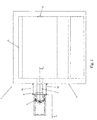
- FIG. 1 represents an overhead view of an embodiment of a furnace plant according to the invention
- FIG. 2 shows a cross-sectional view of a portion of the embodiment shown in FIG. 1 along, the line A-A;
- FIG. 3 is a graph that illustrates a relationship between stirring force and stirring frequency according to one embodiment of the invention.
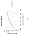
- FIG. 4 is a graph that illustrates a relationship between stirring force and opening width according to one embodiment of the invention.
- FIG. 5 is a graph that illustrates a relationship between stirring force and refractory thickness according to one embodiment of the invention.
- FIG. 6 is a graph that illustrates a relationship between stirring force and displacement according to one embodiment of the invention.
- metal chips, swarf and other alloy elements may accumulate on the surface of the molten metal where they may be oxidized. This can reduce yield.
- the invention concerns a structure and method that can reduce or eliminate such problems.
- the invention includes a structure and method that helps to stir molten metal, introduce solid metal into the molten metal and help to prevent introduction of unwanted materials into the molten metal.
- a structure according to the invention includes more or less typical furnace structure having an additional compartment extending therefrom. At least one stirrer is arranged to stir molten metal within the compartment.
- a plate arranged in the compartment helps to control the flow of molten metal into the compartment from the furnace vessel and out of the compartment into the furnace vessel.
- FIG. 1 illustrates an embodiment of a furnace plant according to the invention.
- the embodiment of the furnace plant shown in FIG. 1 includes a furnace vessel 1 .
- the furnace vessel includes side walls 2 , a bottom 3 and a roof (not shown).
- molten metal is contained within the interior space of the furnace plant.
- the metal may be heated by at least one heater 10 .
- the heater may operate using to a variety of fuels, such as gas and/or electricity.
- the heater heats the metal by radiation and/or convection.
- the heat from the heater maintains molten metal in a liquid state and melts solid metal into a molten state.
- the at least one heater may be arranged in a variety of locations to achieve effective heating of the metal and melting of solid metal.
- the at least one heater could be arranged anywhere around the furnace vessel.
- the at least one heater could be arranged at any of the walls.
- the embodiment shown in FIG. 1 includes two heaters, one arranged at two different walls of the furnace vessel. Other locations that one or more heaters could be arranged include the bottom or roof of the furnace vessel.
- the furnace plant may include as many heaters as necessary.
- the heater may be arranged at any locations about the furnace vessel. For example, a heater could be arranged at two different walls of the furnace vessel, or at the roof and a wall of the furnace vessel, for example.
- a furnace plant according to the invention also includes one or more compartments that extend from the furnace vessel.
- Each compartment includes an interior space that is continuous with the interior space of the furnace plant, such that molten metal may flow between the furnace and the compartment as described below.
- the compartment(s) could be arranged anywhere about the furnace vessel to facilitate operation of the device.
- the compartment(s) could have any desired size.
- the compartment(s) has a small size with respect to the furnace vessel. This can help to concentrate the force on the surface material.
- the invention is particularly useful with aluminum. However, it may be useful in casting other metals, such as lead, copper and zinc. Embodiments of the invention may be utilized with any metal where it is desired to submerge a surface layer during melting of the metal.
- the compartment may be attached to, or be formed as an integral part of a furnace.
- the embodiment of the furnace plant illustrated in FIGS. 1 and 2 includes one compartment 4 that extends from the furnace vessel 1 .
- the compartment may be mounted on the side of the furnace.
- the compartment includes walls 4 a and a bottom 4 b .
- the interior surface 4 c of the bottom may be at a same horizontal level as the interior surface 3 a of the furnace vessel as illustrated in FIG. 2 .
- the walls 4 a of the compartment are sufficiently high to contain the molten metal.
- the walls of the compartment may be as high as the walls of the furnace vessel or may be shorter as in the embodiment shown in FIGS. 1 and 2 .
- the walls of the compartment may be made or any suitable material. If the furnace is being utilized to melt aluminum, the walls of the compartment may be made of steel. If the invention is utilized with other metals, other materials might be used.
- the walls may be lined with refractory material. Examples of refractory materials that may be utilized can include aluminium oxide based refractory materials or silicium carbide based refractory materials, among others.
- a plate 6 of refractory material or a metal plated clad with refractory material is arranged inside of the compartment. Any suitable material may be utilized in this location. According to one embodiment, the plate may be fixed to the sidewall of the compartment, leaving a clearance in the bottom so the metal can flow.
- the refractory plate 6 may be oriented to achieve a desired mixing of molten metal and/or submerging of material into the molten metal. For example, the height of the refractory plate may be changed as well as the distance of the plate relative to one or more walls of the compartment. Additionally, the tilt of the refractory plate may be altered.
- refractory plate is mounted in the extension compartment in an inclined position such that a gap between a side wall of the compartment is narrower toward a top of the compartment as compared to toward the bottom of the compartment, as in the embodiment illustrated in FIGS. 1 and 2 .
- a gap between a side wall of the compartment is narrower toward a top of the compartment as compared to toward the bottom of the compartment, as in the embodiment illustrated in FIGS. 1 and 2 .
- The may be a second, larger gap 8 between the refractory plate and the distal side wall of the extension compartment.
- the orientation of the refractory plate may be altered with respect to the distal side wall or the other side walls of the extension compartment.
- the refractory plate is at least 100 mm from the wall of the furnace vessel and at least 50 mm below the level of the top of the bath.
- the refractory plate may be arranged movable or fixed inside the extension compartment. If the refractory plate is movable, the position of the plate may be moved during the operation of the furnace plant. This can help to optimize performance of the furnace plant as conditions change.
- the refractory plate is positioned such that the upper edge of the plate is lower than the meniscus of molten metal inside the compartment. There is a gap between the refractory plate and the bottom of the extension in order to obtain a flow of molten metal from the extension and into the furnace.
- the gaps between the refractory plate and the side walls of the extension compartment that extend from the side wall of the furnace vessel are as small as possible to facilitate flow of the metal within the compartment and between the compartment and the furnace vessel.
- a wall 7 of refractory material may be arranged inside the furnace, adjacent to the top part of the refractory plate.
- the refractory wall may be attached in a number of different places.
- the refractory wall could be attached to the walls of the extension compartment, walls of the furnace vessel and/or roof of the furnace vessel.
- the refractory wall typically is arranged such that it will be submerged into the molten metal. Positioned in this manner relative to the compartment, furnace vessel and refractory plate will help to prevent dross from entering the compartment.
- the position and orientation of the refractory wall may be altered to control flow of metal, as the level of molten metal in the furnace plant varies, and/or with changing orientation of the refractory plate.
- One or more electromagnetic stirrers are positioned adjacent to the extension compartment.
- the one or more stirrers may be positioned adjacent one or more walls and/or the bottom of the extension compartment.
- the embodiment shown in FIGS. 1 and 2 includes one stirrer 5 arranged adjacent a wall of the extension compartment distal to the furnace vessel.
- a wall of the extension compartment that a stirrer is arranged adjacent may be made of austenitic steel in a furnace plant for melting aluminum.
- a position of the one or more stirrers may be altered.
- the height of any of stirrer arranged adjacent a side wall of the extension compartment may be adjustable.
- the stirrer may be oriented to operate downwards. In such an arrangement, the stirrer may generate a downwardly travelling electromagnetic field into the compartment containing molten metal. The magnetic field moves the molten metal downwards against the bottom of the compartment and further into the furnace.
- the main stirring force may be imposed in a first area (Area X) behind the refractory plate and below the meniscus of the molten metal held in the compartment.
- a second area (Area Y) is positioned below the meniscus and above the first area (Area X).
- Area Y may be made smaller by repositioning the refractory plate. This can make it possible to accelerate the velocity of molten metal at the meniscus in the compartment. Accelerating the molten metal in turn allows material added at the meniscus to be submerged into the molten metal.
- the stirring force exhibited by the stirrer(s) on the molten metal may vary with the frequency with which the stirrer(s).
- FIG. 3 illustrates a relationship between stirring force and stirring frequency according to one embodiment of the invention.
- Stirring force exhibited on the molten metal may also vary with the width of the opening in the compartment.
- FIG. 4 illustrates a relationship between stirring force and opening width according to one embodiment of the invention.
- Stirring force exhibited on the molten metal may also vary with the thickness of the refractory.
- FIG. 5 illustrates a relationship between stirring force and refractory thickness according to one embodiment of the invention. Stirring force exhibited on the molten metal may also vary with positioning of the stirrer relative to the vertical center of the compartment.
- FIG. 3 illustrates a relationship between stirring force and stirring frequency according to one embodiment of the invention.
- Stirring force exhibited on the molten metal may also vary with the width of the opening in the compartment.
- FIG. 4 illustrates a relationship between stirring force and
- the stirrer can generate a maximum velocity of about 2.7 m/s in downward stirring and about 3.2 m/s in upward stirring.
- the stirrer can generate a maximum velocity of about 3.8 m/s in downward stirring.
- the stirrer may impose an upwardly travelling electromagnetic field into the compartment, containing molten metal. This electromagnetic field moves the molten metal upwards against and over the top of the refractory plate and further back into the furnace.
- Embodiments of the invention make it possible to use a common electromagnetic stirrer in order to create a high velocity of molten metal, in the compartment, at the meniscus sufficient to cause metal chips, swarf and other alloy elements to be easily submerged into the bath of molten metal in the compartment.
- a common electromagnetic stirrer in order to create a high velocity of molten metal, in the compartment, at the meniscus sufficient to cause metal chips, swarf and other alloy elements to be easily submerged into the bath of molten metal in the compartment.
- these types of materials do not sink under the meniscus by gravity alone. Rather, they float on the meniscus exposed to the surface environment, which oxidises the materials and causes losses in yield.
Landscapes
- Engineering & Computer Science (AREA)
- Mechanical Engineering (AREA)
- Chemical & Material Sciences (AREA)
- General Engineering & Computer Science (AREA)
- Organic Chemistry (AREA)
- Metallurgy (AREA)
- Materials Engineering (AREA)
- Manufacturing & Machinery (AREA)
- Environmental & Geological Engineering (AREA)
- Geology (AREA)
- General Life Sciences & Earth Sciences (AREA)
- Life Sciences & Earth Sciences (AREA)
- Vertical, Hearth, Or Arc Furnaces (AREA)
- Waste-Gas Treatment And Other Accessory Devices For Furnaces (AREA)
- Physical Or Chemical Processes And Apparatus (AREA)
- Mixers Of The Rotary Stirring Type (AREA)
Priority Applications (1)
| Application Number | Priority Date | Filing Date | Title |
|---|---|---|---|
| US12/682,355 US8043403B2 (en) | 2007-10-09 | 2008-10-09 | Device for submerging material into liquid metal by an electromagnetic stirrer |
Applications Claiming Priority (3)
| Application Number | Priority Date | Filing Date | Title |
|---|---|---|---|
| US96066807P | 2007-10-09 | 2007-10-09 | |
| US12/682,355 US8043403B2 (en) | 2007-10-09 | 2008-10-09 | Device for submerging material into liquid metal by an electromagnetic stirrer |
| PCT/IB2008/002673 WO2009047624A1 (en) | 2007-10-09 | 2008-10-09 | Device for submerging material into liquid metal by an electromagnetic stirrer |
Publications (2)
| Publication Number | Publication Date |
|---|---|
| US20100236362A1 US20100236362A1 (en) | 2010-09-23 |
| US8043403B2 true US8043403B2 (en) | 2011-10-25 |
Family
ID=40242716
Family Applications (1)
| Application Number | Title | Priority Date | Filing Date |
|---|---|---|---|
| US12/682,355 Expired - Fee Related US8043403B2 (en) | 2007-10-09 | 2008-10-09 | Device for submerging material into liquid metal by an electromagnetic stirrer |
Country Status (6)
| Country | Link |
|---|---|
| US (1) | US8043403B2 (de) |
| EP (1) | EP2198228B8 (de) |
| KR (1) | KR101461260B1 (de) |
| CN (1) | CN101821574B (de) |
| AT (1) | ATE546555T1 (de) |
| WO (1) | WO2009047624A1 (de) |
Cited By (1)
| Publication number | Priority date | Publication date | Assignee | Title |
|---|---|---|---|---|
| US20140284854A1 (en) * | 2012-09-27 | 2014-09-25 | Kenzo Takahashi | Metal melting furnace vortex chamber body and metal melting furnace using the same |
Families Citing this family (3)
| Publication number | Priority date | Publication date | Assignee | Title |
|---|---|---|---|---|
| JP5766572B2 (ja) * | 2011-09-30 | 2015-08-19 | 高橋 謙三 | 金属溶解炉用渦室体及びそれを用いた金属溶解炉 |
| GB2536185A (en) * | 2014-08-08 | 2016-09-14 | Fives Solios Ltd | Method and apparatus for submerging materials into a molten material bath |
| CN107630145A (zh) * | 2017-09-20 | 2018-01-26 | 李益隆 | 介质发热熔铝的方法 |
Citations (2)
| Publication number | Priority date | Publication date | Assignee | Title |
|---|---|---|---|---|
| GB2266896A (en) | 1992-04-24 | 1993-11-17 | Miyamoto Kogyosho Kk | Process and apparatus for melting aluminium alloy scraps |
| US5456452A (en) * | 1994-01-11 | 1995-10-10 | Magneco/Metrel, Inc. | Apparatus for making steel alloys in a tundish |
Family Cites Families (5)
| Publication number | Priority date | Publication date | Assignee | Title |
|---|---|---|---|---|
| CA1226738A (en) * | 1983-03-14 | 1987-09-15 | Robert J. Ormesher | Metal scrap reclamation system |
| CA1330486C (en) * | 1988-05-20 | 1994-07-05 | Marc-Andre Thibault | Apparatus for stirring molten metal |
| SE504400C2 (sv) * | 1995-04-25 | 1997-02-03 | Asea Brown Boveri | Ugnsanläggning för smältning av metall och/eller varmhållning av smält metall |
| FR2815642B1 (fr) * | 2000-10-20 | 2003-07-11 | Pechiney Rhenalu | Dispositif rotatif de dispersion de gaz pour le traitement d'un bain de metal liquide |
| KR20140014588A (ko) * | 2012-07-25 | 2014-02-06 | 주식회사 큐빅스 | 고효율 알루미늄 전기용해로 제어장치 |
-
2008
- 2008-10-09 EP EP08807219A patent/EP2198228B8/de not_active Not-in-force
- 2008-10-09 KR KR1020107007596A patent/KR101461260B1/ko not_active Expired - Fee Related
- 2008-10-09 US US12/682,355 patent/US8043403B2/en not_active Expired - Fee Related
- 2008-10-09 WO PCT/IB2008/002673 patent/WO2009047624A1/en not_active Ceased
- 2008-10-09 CN CN2008801107009A patent/CN101821574B/zh not_active Expired - Fee Related
- 2008-10-09 AT AT08807219T patent/ATE546555T1/de active
Patent Citations (3)
| Publication number | Priority date | Publication date | Assignee | Title |
|---|---|---|---|---|
| GB2266896A (en) | 1992-04-24 | 1993-11-17 | Miyamoto Kogyosho Kk | Process and apparatus for melting aluminium alloy scraps |
| US5385338A (en) * | 1992-04-24 | 1995-01-31 | Miyamoto Kogyosho Co., Ltd. | Apparatus for melting aluminum alloy scraps |
| US5456452A (en) * | 1994-01-11 | 1995-10-10 | Magneco/Metrel, Inc. | Apparatus for making steel alloys in a tundish |
Non-Patent Citations (4)
| Title |
|---|
| PCT/ISA/210-International Search Report-Jan. 29, 2009. |
| PCT/ISA/210—International Search Report—Jan. 29, 2009. |
| PCT/ISA/237-Written Opinion of the International Searching Authority-Jan. 29, 2009. |
| PCT/ISA/237—Written Opinion of the International Searching Authority—Jan. 29, 2009. |
Cited By (2)
| Publication number | Priority date | Publication date | Assignee | Title |
|---|---|---|---|---|
| US20140284854A1 (en) * | 2012-09-27 | 2014-09-25 | Kenzo Takahashi | Metal melting furnace vortex chamber body and metal melting furnace using the same |
| US9488415B2 (en) * | 2012-09-27 | 2016-11-08 | Kenzo Takahashi | Metal melting furnace vortex chamber body and metal melting furnace using the same |
Also Published As
| Publication number | Publication date |
|---|---|
| CN101821574B (zh) | 2012-07-04 |
| US20100236362A1 (en) | 2010-09-23 |
| KR101461260B1 (ko) | 2014-11-12 |
| ATE546555T1 (de) | 2012-03-15 |
| EP2198228B1 (de) | 2012-02-22 |
| CN101821574A (zh) | 2010-09-01 |
| WO2009047624A1 (en) | 2009-04-16 |
| EP2198228B8 (de) | 2012-10-24 |
| EP2198228A1 (de) | 2010-06-23 |
| KR20100072016A (ko) | 2010-06-29 |
Similar Documents
| Publication | Publication Date | Title |
|---|---|---|
| US8043403B2 (en) | Device for submerging material into liquid metal by an electromagnetic stirrer | |
| GB2515475A (en) | Metallurgical apparatus | |
| RU2443961C2 (ru) | Способ и аппарат для индукционного перемешивания жидкого металла | |
| EP1514065B1 (de) | Elektromagnetisches induktionsgerät und verfahren zur behandlung geschmolzener werkstoffe | |
| JP2001040411A (ja) | 溶鋼の精錬用取鍋 | |
| JP2015040640A (ja) | アルミ溶解保持炉 | |
| US9360255B2 (en) | Method and arrangement for vortex reduction in a metal making process | |
| CA2491645C (en) | Method for fractional crystallisation of a metal | |
| ZA200410141B (en) | Electromagnetic induction apparatus and method of treatment of molten materials | |
| US9416430B2 (en) | Apparatus for inducing flow in a molten material | |
| JP2003261339A (ja) | フロートガラス溶融炉およびガラスを浮融させる方法 | |
| US4375885A (en) | Reverberatory furnace | |
| BR112017022745B1 (pt) | Forno para fundir e tratar metal e resíduo metálico, uso do forno e método para tratar ou fundir metal ou resíduo metálico | |
| US10739074B2 (en) | Metallurgical apparatus | |
| KR20180040587A (ko) | 채널형 유도로 | |
| JP2020139662A (ja) | アーク式電気炉、アーク式電気炉における排滓方法及び溶融金属の製造方法 | |
| WO2001061059A1 (en) | A continuously operating method for producing refined metal | |
| Mills | The effect of interfacial phenomena on materials processing | |
| SU349727A1 (ru) | Устройство для факельно-шлакового переплава | |
| SU1196401A1 (ru) | Способ рафинирования сплавов, содержащих легкоплавкие компоненты | |
| RU2343041C1 (ru) | Способ обогрева и теплоизоляции верхней части кристаллизующегося слитка при разливке в изложницу | |
| JP2003025048A (ja) | 鋼の連続鋳造方法 | |
| Mills | THE EFFECT OF INTERFACIAL PHENOΜΕΝΑ ON MATERIALS PROCESSING | |
| GB2536185A (en) | Method and apparatus for submerging materials into a molten material bath | |
| UA75536C2 (en) | A method for metallurgical processing iron-containing material and a mechanism for realizing the same |
Legal Events
| Date | Code | Title | Description |
|---|---|---|---|
| AS | Assignment |
Owner name: ABB AB, SWEDEN Free format text: ASSIGNMENT OF ASSIGNORS INTEREST;ASSIGNORS:RYDHOLM, BENGT;SVENSSON, ERIK;LUNDSTROM, ALF;AND OTHERS;SIGNING DATES FROM 20100219 TO 20100310;REEL/FRAME:024222/0573 |
|
| FEPP | Fee payment procedure |
Free format text: PAYOR NUMBER ASSIGNED (ORIGINAL EVENT CODE: ASPN); ENTITY STATUS OF PATENT OWNER: LARGE ENTITY |
|
| STCF | Information on status: patent grant |
Free format text: PATENTED CASE |
|
| FEPP | Fee payment procedure |
Free format text: PAYOR NUMBER ASSIGNED (ORIGINAL EVENT CODE: ASPN); ENTITY STATUS OF PATENT OWNER: LARGE ENTITY Free format text: PAYER NUMBER DE-ASSIGNED (ORIGINAL EVENT CODE: RMPN); ENTITY STATUS OF PATENT OWNER: LARGE ENTITY |
|
| FPAY | Fee payment |
Year of fee payment: 4 |
|
| FEPP | Fee payment procedure |
Free format text: MAINTENANCE FEE REMINDER MAILED (ORIGINAL EVENT CODE: REM.); ENTITY STATUS OF PATENT OWNER: LARGE ENTITY |
|
| LAPS | Lapse for failure to pay maintenance fees |
Free format text: PATENT EXPIRED FOR FAILURE TO PAY MAINTENANCE FEES (ORIGINAL EVENT CODE: EXP.); ENTITY STATUS OF PATENT OWNER: LARGE ENTITY |
|
| STCH | Information on status: patent discontinuation |
Free format text: PATENT EXPIRED DUE TO NONPAYMENT OF MAINTENANCE FEES UNDER 37 CFR 1.362 |
|
| FP | Lapsed due to failure to pay maintenance fee |
Effective date: 20191025 |