EP2197103A2 - Geschwindigkeitssteuerung eines Magnetmotors - Google Patents
Geschwindigkeitssteuerung eines Magnetmotors Download PDFInfo
- Publication number
- EP2197103A2 EP2197103A2 EP09015390A EP09015390A EP2197103A2 EP 2197103 A2 EP2197103 A2 EP 2197103A2 EP 09015390 A EP09015390 A EP 09015390A EP 09015390 A EP09015390 A EP 09015390A EP 2197103 A2 EP2197103 A2 EP 2197103A2
- Authority
- EP
- European Patent Office
- Prior art keywords
- value
- axis
- speed
- commanded
- detected
- Prior art date
- Legal status (The legal status is an assumption and is not a legal conclusion. Google has not performed a legal analysis and makes no representation as to the accuracy of the status listed.)
- Granted
Links
Images


Classifications
-
- H—ELECTRICITY
- H02—GENERATION; CONVERSION OR DISTRIBUTION OF ELECTRIC POWER
- H02P—CONTROL OR REGULATION OF ELECTRIC MOTORS, ELECTRIC GENERATORS OR DYNAMO-ELECTRIC CONVERTERS; CONTROLLING TRANSFORMERS, REACTORS OR CHOKE COILS
- H02P23/00—Arrangements or methods for the control of AC motors characterised by a control method other than vector control
- H02P23/14—Estimation or adaptation of motor parameters, e.g. rotor time constant, flux, speed, current or voltage
-
- H—ELECTRICITY
- H02—GENERATION; CONVERSION OR DISTRIBUTION OF ELECTRIC POWER
- H02P—CONTROL OR REGULATION OF ELECTRIC MOTORS, ELECTRIC GENERATORS OR DYNAMO-ELECTRIC CONVERTERS; CONTROLLING TRANSFORMERS, REACTORS OR CHOKE COILS
- H02P6/00—Arrangements for controlling synchronous motors or other dynamo-electric motors using electronic commutation dependent on the rotor position; Electronic commutators therefor
- H02P6/08—Arrangements for controlling the speed or torque of a single motor
- H02P6/085—Arrangements for controlling the speed or torque of a single motor in a bridge configuration
-
- H—ELECTRICITY
- H02—GENERATION; CONVERSION OR DISTRIBUTION OF ELECTRIC POWER
- H02P—CONTROL OR REGULATION OF ELECTRIC MOTORS, ELECTRIC GENERATORS OR DYNAMO-ELECTRIC CONVERTERS; CONTROLLING TRANSFORMERS, REACTORS OR CHOKE COILS
- H02P21/00—Arrangements or methods for the control of electric machines by vector control, e.g. by control of field orientation
- H02P21/22—Current control, e.g. using a current control loop
-
- H—ELECTRICITY
- H02—GENERATION; CONVERSION OR DISTRIBUTION OF ELECTRIC POWER
- H02P—CONTROL OR REGULATION OF ELECTRIC MOTORS, ELECTRIC GENERATORS OR DYNAMO-ELECTRIC CONVERTERS; CONTROLLING TRANSFORMERS, REACTORS OR CHOKE COILS
- H02P25/00—Arrangements or methods for the control of AC motors characterised by the kind of AC motor or by structural details
- H02P25/02—Arrangements or methods for the control of AC motors characterised by the kind of AC motor or by structural details characterised by the kind of motor
- H02P25/022—Synchronous motors
- H02P25/024—Synchronous motors controlled by supply frequency
-
- H—ELECTRICITY
- H02—GENERATION; CONVERSION OR DISTRIBUTION OF ELECTRIC POWER
- H02P—CONTROL OR REGULATION OF ELECTRIC MOTORS, ELECTRIC GENERATORS OR DYNAMO-ELECTRIC CONVERTERS; CONTROLLING TRANSFORMERS, REACTORS OR CHOKE COILS
- H02P29/00—Arrangements for regulating or controlling electric motors, appropriate for both AC and DC motors
- H02P29/02—Providing protection against overload without automatic interruption of supply
- H02P29/024—Detecting a fault condition, e.g. short circuit, locked rotor, open circuit or loss of load
- H02P29/027—Detecting a fault condition, e.g. short circuit, locked rotor, open circuit or loss of load the fault being an over-current
-
- H—ELECTRICITY
- H02—GENERATION; CONVERSION OR DISTRIBUTION OF ELECTRIC POWER
- H02P—CONTROL OR REGULATION OF ELECTRIC MOTORS, ELECTRIC GENERATORS OR DYNAMO-ELECTRIC CONVERTERS; CONTROLLING TRANSFORMERS, REACTORS OR CHOKE COILS
- H02P6/00—Arrangements for controlling synchronous motors or other dynamo-electric motors using electronic commutation dependent on the rotor position; Electronic commutators therefor
- H02P6/06—Arrangements for speed regulation of a single motor wherein the motor speed is measured and compared with a given physical value so as to adjust the motor speed
-
- H—ELECTRICITY
- H02—GENERATION; CONVERSION OR DISTRIBUTION OF ELECTRIC POWER
- H02P—CONTROL OR REGULATION OF ELECTRIC MOTORS, ELECTRIC GENERATORS OR DYNAMO-ELECTRIC CONVERTERS; CONTROLLING TRANSFORMERS, REACTORS OR CHOKE COILS
- H02P6/00—Arrangements for controlling synchronous motors or other dynamo-electric motors using electronic commutation dependent on the rotor position; Electronic commutators therefor
- H02P6/14—Electronic commutators
- H02P6/16—Circuit arrangements for detecting position
-
- H—ELECTRICITY
- H02—GENERATION; CONVERSION OR DISTRIBUTION OF ELECTRIC POWER
- H02P—CONTROL OR REGULATION OF ELECTRIC MOTORS, ELECTRIC GENERATORS OR DYNAMO-ELECTRIC CONVERTERS; CONTROLLING TRANSFORMERS, REACTORS OR CHOKE COILS
- H02P2207/00—Indexing scheme relating to controlling arrangements characterised by the type of motor
- H02P2207/05—Synchronous machines, e.g. with permanent magnets or DC excitation
-
- H—ELECTRICITY
- H02—GENERATION; CONVERSION OR DISTRIBUTION OF ELECTRIC POWER
- H02P—CONTROL OR REGULATION OF ELECTRIC MOTORS, ELECTRIC GENERATORS OR DYNAMO-ELECTRIC CONVERTERS; CONTROLLING TRANSFORMERS, REACTORS OR CHOKE COILS
- H02P2209/00—Indexing scheme relating to controlling arrangements characterised by the waveform of the supplied voltage or current
- H02P2209/07—Trapezoidal waveform
Definitions
- the present invention relates to a technology for controlling speed of a magnetic motor.
- Japanese Patent Application Laid-open No. 2005-033957 describes a protective control method of calculating a voltage saturation rate standing for a degree of voltage saturation, from an input voltage inputted to a power converter for driving the magnetic motor and a commanded voltage value given to the magnetic motor and of lowering a target rotation speed value given from the outside until when the voltage saturation rate becomes smaller than a voltage saturation rate preset value.
- this method described in JPA 2005-033957 has a problem which results from its control principle, the problem that the maximum use can not be made of the voltage saturation rate because this method requires the voltage saturation rate to be set smaller than the preset voltage saturation rate value. That is, this method has a problem that the maximum voltage of the power converter cannot be applied to the motor and as a consequence, the maximum use can not be made of the upper limit torque of the motor.
- the present invention aims at providing a speed controller of a permanent magnetic motor, an air conditioner and a screw compressor capable of making the maximum use of the voltage saturation rate and completing a controller of a magnetic motor, an air-conditioner and a screw compressor which are capable of operating with high stability, high efficiency and quick response upto the upper limit torque of the motor.
- the present invention is characterized in that if a phase angle between commanded voltage values of d-axis (magnetic flux axis) and q-axis (torque axis) of vector control increases to a predetermined value or more, an input of speed control is limited so that a q-axis commanded current value that is an output of the speed control does not increase to an upper limit value.
- the present invention has a first feature of a speed controller of a magnetic motor for: calculating d-axis and q-axis commanded voltage values, the d-axis and the q-axis corresponding respectively to a magnetic flux axis and a torque axis, and the d-axis and q-axis commanded voltage values being calculated based on d-axis and q-axis commanded current values, d-axis and q-axis detected current values and a detected speed values, the d-axis commanded current value set to zero and the q-axis commanded current value calculated from a deviation of a commanded speed value from the detected speed value, and controlling an output voltage value from a power converter for driving the magnetic motor in accordance with the calculated d-axis and q-axis commanded voltage values, the speed controller limiting a speed control input to keep the q-axis commanded current value from increasing to an upper limit value if a
- the present invention has a second feature of a speed controller of a magnetic motor for: calculating d-axis and q-axis commanded voltage values, the d-axis and the q-axis corresponding respectively to a magnetic flux axis and a torque axis, and the d-axis and q-axis commanded voltage values being calculated based on d-axis and q-axis commanded current values, d-axis and q-axis detected current values and a detected speed values, the d-axis commanded current value set to zero and the q-axis commanded current value calculated from a deviation of a commanded speed value from the detected speed value, and controlling an output voltage value from a power converter for driving the magnetic motor by changing a commanded phase value in accordance with a deviation of the q-axis commanded current value from the q-axis detected current value if the output voltage value from the power converter is limited, the speed controller limiting a speed control input to keep the q-
- the present invention has a third feature of a speed controller of a magnetic motor comprising a speed control calculation section to which a second commanded speed value is inputted to limit the speed control input, the second commanded speed value being equal to what is left after subtracting a speed correction value from a first commanded speed value given by an upper level section, the speed correction value being calculated to have the second commanded speed value equal to the detected speed value.
- the present invention has a fourth feature of a speed controller of a magnetic motor comprising a speed control calculation section to which a second detected speed value is inputted to limit the speed control input, the second detected speed value being equal to a summation of the detected speed value and a speed correction value being calculated so as to have the second detected speed value equal to the first commanded speed value.
- the present invention has a fifth feature of a speed controller of a magnetic motor wherein the speed correction value is generated by proportion and integration calculations of a deviation of the second commanded speed value to be inputted to the speed control calculation section from the detected speed value or a deviation of the first commanded speed value from the second detected speed value.
- the present invention has a sixth feature of a speed controller of a magnetic motor wherein if the deviation of the commanded speed value from the detected speed value is a positive value, the deviation is made zero with the positive value skipped, the deviation which is to be inputted to the speed control calculation section where calculation on integration control or the proportion and integration control is performed.
- the present invention has a seventh feature of a speed controller of a magnetic motor wherein the speed controller determines that the greater torque than the maximum torque is applied if a phase angle between the d-axis commanded voltage value and the q-axis commanded voltage value is equal to or greater than 70 degrees.
- the present invention has a eighth feature of a speed controller of a magnetic motor wherein the speed controller determines that the output voltage value from the power converter is limited if a ratio of an average value on the output voltage values to a DC voltage value is substantially 1.
- the present invention is an air conditioner to which a speed controller of a magnetic motor with the first feature is applied.
- the present invention is a screw compressor to which a speed controller of a magnetic motor with the first feature is applied.
- the invention is capable of providing the speed controller of the permanent magnetic motor capable of keeping the high stability, high efficiency and quick response even when the motor is outputting the upper limit torque.
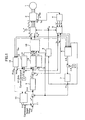
- FIG. 1 is a block diagram illustrating a configuration of a speed controller of a magnetic motor according to one embodiment of the invention.
- the magnetic motor 1 outputs motor torque in which a torque component caused by magnetic flux of a permanent magnetic and a torque component caused by inductance of an armature coils are combined.
- a power converter 2 outputs voltages which are proportional to three-phase commanded AC voltage values V U *, V V * and V W *, and varies the output voltages and rotational speed of the magnetic motor 1.
- a DC power supply 3 supplies DC voltage E DC to the power converter 2.
- a current estimating section 4 reproduces the three-phase AC currents (i U , i V , i W ) from the DC current I DC flowing through one-shunt resistance R S attached to detect an over-current of the power converter 2 and outputs i U ⁇ , i V ⁇ and i W ⁇ .
- a coordinate converting section 5 calculates and outputs detected current values I dc and I qc of d and q-axes by using the reproduced values of the three-phase AC currents i U ⁇ , i V ⁇ and i W ⁇ described above and an estimated phase value ⁇ dc .
- An axial error estimating section 6 performs estimate-calculation of an axial error ⁇ that is a deviation between the estimated phase value ⁇ dc and a phase value ⁇ d of the motor and outputs an estimated value ⁇ c , based on commanded voltage values V dc ** and V qc **, an estimated speed value ⁇ 1c , detected current values I dc and I qe and a motor constant.
- a speed estimating section 7 performs both proportion calculation and integration calculations of a deviation between a command value of the axial error ⁇ and the estimated value of the axial error ⁇ and outputs an estimated speed value ⁇ 1c .
- a phase estimating section 8 integrates the estimated speed value ⁇ 1c and outputs an estimated phase value ⁇ dc .
- a speed control calculation section 9 performs both proportion and integration calculations so that the estimated speed value ⁇ 1c follows a second commanded speed value ⁇ * and outputs a q axis commanded current value I q *.
- a speed command correction calculating section 10 outputs a speed correction value ⁇ * based on the speed deviation value ⁇ between the second commanded speed value ⁇ * and the estimated speed value ⁇ 1c and a voltage phase limiting flag ⁇ lmt flg .
- An adding section 11 adds the speed correction value ⁇ * to the first commanded speed value ⁇ 0 * given from an upper level to output a second commanded speed value ⁇ *.
- a d-axis current control calculation section 12 operates as follows depending on the voltage value limiting flag Vlmt flg . That is, when the voltage value limiting flag Vlmt flg is "zero", the d-axis current control calculation section 12 performs both proportion and integration calculations so that the detected current value I dc of the d-axis follows the first d-axis commanded current value I d * to calculate ⁇ I d ** and outputs a second d-axis commanded current value I d **.
- a q-axis current control calculation section 13 operates as follows depending on the voltage value limiting flag Vlmt flg ,.
- the q-axis current control calculation section 13 performs both proportion and integration calculations so that the detected current value I qc of the q-axis follows the first q-axis commanded current value I q * that is the output of the speed control calculation section 9 to calculate ⁇ I q ** and outputs as a second q-axis commanded current value I q **.
- the q-axis current control calculation section 13 holds the previous value without updating ⁇ I q **, adds to I q * and outputs a second q-axis commanded current value I q **.
- a phase error command calculating section 14 operates as follows depending on the voltage value limiting flag Vlmt flg .
- phase error command calculating section 14 When the voltage value limiting flag Vlmt flg is "zero", the phase error command calculating section 14 outputs a command value of phase error ⁇ e as "zero".
- the phase error command calculating section 14 performs proportion and integration calculations so that the detected current value I qc of the q-axis follows the first q-axis commanded current value I q * that is the output of the speed control calculation section 9 and outputs a command value of the phase error ⁇ e * .
- a vector control calculation section 15 calculates and outputs commanded voltage values V dc **and V qc ** based on an electric constant of the magnetic motor 1, the second commanded current values I d ** and I q **, the estimated speed value ⁇ 1c and the command value of the phase error ⁇ e *.
- a voltage limit detecting section 16 outputs the voltage value limiting flag Vlmt flg and the voltage phase limiting flag ⁇ lmt flg based on the commanded voltage values V dc ** and V qc ** of the d-axis and q-axis and the DC voltage value E DC .
- a coordinate converting section 17 outputs commanded voltage values of three-phase AC V u **, I v ** and V w ** by using the d-axis and q-axis commanded voltage values V dc ** and V qc ** and the estimated position value ⁇ dc .
- the basic operation of the voltage control is carried out by the voltage limit detecting section 16 in FIG. 1 that calculates a voltage value V* by using the d-axis and q-axis commanded voltage values V dc ** and V qc ** according to the following Equation 1.
- V * V dc * * 2 + V qc * * 2
- the voltage value limiting flag Vlmt flg is generated by using V* and the DC voltage value E DC according to the following Equation 2.
- the d-axis and q-axis current control calculation sections 12 and 13 output the second commanded current values I d ** and I q ** so that the detected current values I dc and I qc follow respectively the first commanded current values I d * and I q * according to the following Equation 3.
- I d * * I d * + ⁇ ⁇ I d * *
- I q * * I q * + ⁇ ⁇ I q * *
- the vector control calculation section 15 calculates the commanded voltage values V dc ** and V q ** by using the second commanded current values I d ** and I q **, the constant of the magnetic motor 1 and the estimated speed value ⁇ 1c , according to the following Equation 4.
- V dc * V qc * R * - ⁇ 1 ⁇ c ⁇ L q * ⁇ 1 ⁇ c ⁇ L d * R * ⁇ I d * * I q * * + 0 ⁇ 1 ⁇ c ⁇ K e *
- R is a resistance value
- L d is an inductance value of the d-axis
- Lq is an inductance value of the q-axis
- K e is a coefficient of induced voltage
- * is a preset value.
- the vector control calculation section 15 also calculates new commanded voltage values V dc ** and V qc ** by using Equation 4 and the command value of the phase error ⁇ e * according to Equation 5 to control the output voltage of the power converter 2.
- V dc * * V qc * * V dc * V qc * ⁇ cos ⁇ ⁇ ⁇ e * - sin ⁇ ⁇ ⁇ e * sin ⁇ ⁇ ⁇ e * cos ⁇ ⁇ ⁇ e *
- This control method enables performing "field-weakening control" intended for enlarging a high speed torque range by using the command value of the phase error ⁇ e * while I d * is kept set to "zero".
- ⁇ ⁇ ⁇ c tan - 1 ⁇ V dc * * - R * ⁇ I dc + ⁇ 1 ⁇ c ⁇ L q * ⁇ I qc V qc * * - R * ⁇ I qc - ⁇ 1 ⁇ c ⁇ L q * ⁇ I dc
- the speed estimating section 7 also performs both proportion and integration calculations to control the estimated speed value ⁇ 1c SO that the axial error estimated value ⁇ becomes "zero".
- the phase estimating section 8 integrates the estimated speed value ⁇ 1c to control the estimated phase value ⁇ dc .
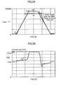
- FIG. 2 shows operation characteristics when a trapezoidal wave signal of the commanded speed value ⁇ * is given.
- Fig.2A shows waveforms of the first commanded speed value ⁇ 0* and the estimated speed value ⁇ 1c and the lower part the figure shows a waveform of the q-axis commanded current value I q *.
- the following characteristic may be worsened even more if a control gain of the speed control calculation section 9 is low, which possibly results in a shutdown due to an over-current trip.
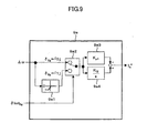
- the voltage limit detecting section 16 shown in FIG. 3 will be explained.
- the commanded voltage values V dc ** and V qc ** are inputted to an output voltage calculating section 161 to calculate a signal V* according to the following Equation 7.
- V * V dc * * 2 + V qc * * 2
- This signal V* and the signal E DC are inputted to a comparing section 162 that outputs the voltage value limiting flag Vlmtflg of "0" or "1” according to Equation 1 described above.
- the commanded voltage values V dc ** and V qc ** are inputted also to a voltage phase calculating section 163 that calculates a voltage phase ⁇ that is a phase angle between the commanded voltage values V dc ** and V qc ** according to the following Equation 8.
- a signal ⁇ lmt 164 indicates a value of the voltage phase during the critical torque.
- the signal ⁇ lmt 164 will be explained below.
- FIG. 4 shows a relationship among the speed ⁇ , the critical torque and the voltage phase (during the critical torque).
- This threshold value is the signal ⁇ lmt 164 and may be preset by studying it by means of numerical analysis and an actual apparatus in advance.
- the value of the DC voltage E dc is more or less constant, the value of the voltage phase during the maximum speed and critical torque may be preset as the signal ⁇ lmt.
- the threshold value may be output as a map for reading the signal ⁇ lmt by E DC .
- the signal 8 and the signal ⁇ lmt are inputted to the comparing section 165 that outputs the voltage phase limiting flag ⁇ lmt flg of "0" or "1” according to Equation 9.
- the speed deviation value ⁇ and the voltage phase limiting flag ⁇ lmt flg described above are inputted to a switching section 101 to select an output signal according to Equation 10.
- the output signal of the switching section 101 is inputted to a proportion calculating section 102 in which a proportional constant is K p and to an integration calculating section 103 in which an integration constant is K j and an added value of output signals of the proportion and integration calculating sections 102 and 103 is outputted as the speed correction value ⁇ *.
- the adding section 11 calculates the second commanded speed value ⁇ * by using the first commanded speed value ⁇ ** and the speed correction value ⁇ * according to Equation 11.
- the calculated ⁇ * is inputted to the speed control calculation section 9 as an input signal:
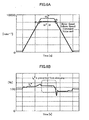
- FIG. 6 shows control characteristics when "the speed command correction calculating section 10" and “the voltage limit detecting section 16" of the present invention are employed.
- the estimated speed value ⁇ 1c may be corrected by using the speed correction value ⁇ *.
- FIG. 7 shows this embodiment.
- each of the components 1 through 10 and 12 through 17 corresponds to one with the same number in FIG. 1 .
- a subtracting section 11 a outputs the second estimated speed value ⁇ 1c by using the estimated speed value ⁇ 1c and the speed correction value ⁇ * according to Equation 12.
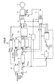
- FIG. 8 shows a still other embodiment of the invention.
- the input signal of the speed control calculation section 9 is limited by using information limiting the voltage phase.
- FIG. 8 the components 1 through 8 and 10 through 17 are the same with those in FIG. 1 .
- a speed control calculation section 9a outputs the q-axis commanded current value I q * by using the speed deviation value ⁇ and the voltage phase limiting flag ⁇ lmt flg .
- the speed deviation value ⁇ is inputted to a speed deviation limiting section 9al that outputs a signal according to Equation 13.
- the speed deviation value ⁇ , the signal ⁇ ' and the voltage phase limiting flag ⁇ lmt flg are inputted to a switching section 9a2 to select an output signal according to Equation 14.
- the output signal of the switching section 9a2 is inputted to a proportion calculating section 9a3 in which a proportional constant is K pl and to an integration calculating section 9a4 in which an integration constant is K il and an added value of output signals of the proportion and integration calculating sections 9a3 and 9a4 is outputted as a q-axis commanded current value I q *.
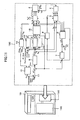
- FIG. 10 shows a different embodiment of the invention.
- the present invention is applied to an air conditioner.
- Each of the components 1 through 17 in the figure corresponds to one with the same number in FIG. 1 .
- the air conditioner 18 is composed of an indoor unit 181, an outdoor unit 182 and a pipe 183.
- a power converter controller 182a controls a magnetic motor 182b to drive a compressor 182c that compresses refrigerant.
- the components 1 through 17 in FIG. 1 are installed in the air conditioner with software and hardware circuits.
- the air conditioner having the highly efficient and quick response control characteristics may be completed by thus applying the invention to the air conditioner.
- FIG. 11 shows another embodiment of the invention.
- the present the invention is applied to a screw compressor.
- a screw compressor 192 containing the magnetic motor 1 receives the commanded speed value ⁇ * from a control panel 191 and is controlled and driven by a power converter controller 193.
- the components 1 through 17 in FIG. 1 are installed in the screw compressor with software and hardware circuits.
- the screw compressor having the highly efficient and quick response control characteristics may be completed by thus applying the invention to the screw compressor.
- the invention is applicable also to a vector control method of generating voltage correction values ⁇ V d and ⁇ V q from the first commanded current values I d * and I q * and the detected current values I dc and I qc and calculating commanded voltage values V dc ** and V qc ** by using the voltage correction values, the first commanded current values I d * and I q *, the estimated speed value ⁇ 1c and the constant of the magnetic motor 1 according to Equation 15.
- V dc * * V qc * * R * - ⁇ 1 ⁇ c ⁇ L q * ⁇ 1 ⁇ c ⁇ L d * R * ⁇ I d * I q * + 0 ⁇ 1 ⁇ c ⁇ K e * + ⁇ V d ⁇ V q
- the three-phase motor currents are reproduced from the DC current I DC flowing through the one-shunt resistance R s attached for detecting over-current of the power converter 2 and the reproduced currents i u ⁇ , i v ⁇ and i w ⁇ are used for the control in the first through third embodiments, AC currents i u , i v and i w directly detected by the current detector may be also applied.
- position sensor-less control from which positional information of the magnetic motor 1 is cut has been used in the first through third embodiments, it is possible to apply position ⁇ detected by an encoder, a resolver, a magnetic pole position sensor and others that are capable of directly detecting the position.
- the speed ⁇ may be calculated according to Equation 16.
- the invention can provide the highly stable and highly efficient magnetic motor.
Landscapes
- Engineering & Computer Science (AREA)
- Power Engineering (AREA)
- Control Of Ac Motors In General (AREA)
- Control Of Motors That Do Not Use Commutators (AREA)
- Control Of Electric Motors In General (AREA)
Applications Claiming Priority (1)
| Application Number | Priority Date | Filing Date | Title |
|---|---|---|---|
| JP2008316348A JP5256009B2 (ja) | 2008-12-12 | 2008-12-12 | 磁石モータの速度制御装置 |
Publications (3)
| Publication Number | Publication Date |
|---|---|
| EP2197103A2 true EP2197103A2 (de) | 2010-06-16 |
| EP2197103A3 EP2197103A3 (de) | 2014-01-22 |
| EP2197103B1 EP2197103B1 (de) | 2015-07-08 |
Family
ID=42136134
Family Applications (1)
| Application Number | Title | Priority Date | Filing Date |
|---|---|---|---|
| EP09015390.9A Active EP2197103B1 (de) | 2008-12-12 | 2009-12-11 | Drehzahlsteuerung eines Magnetmotors |
Country Status (5)
| Country | Link |
|---|---|
| US (1) | US8344671B2 (de) |
| EP (1) | EP2197103B1 (de) |
| JP (1) | JP5256009B2 (de) |
| KR (1) | KR101108402B1 (de) |
| CN (1) | CN101902186B (de) |
Cited By (4)
| Publication number | Priority date | Publication date | Assignee | Title |
|---|---|---|---|---|
| CN101977000A (zh) * | 2010-09-21 | 2011-02-16 | 中国矿业大学 | 电励磁同步电动机的转子位置与速度测量方法及控制装置 |
| EP2831995A4 (de) * | 2012-03-27 | 2015-11-25 | Byd Co Ltd | Verfahren zur regelung der drehzahl eines elektromotors |
| FR3043218A1 (fr) * | 2015-11-04 | 2017-05-05 | Thales Sa | Dispositif de limitation dynamique et procede de limitation dynamique par un tel dispositf |
| EP3220537A3 (de) * | 2016-03-14 | 2018-03-21 | Omron Corporation | Motorsteuerungsvorrichtung, motorsteuerungsverfahren, steuerungssystem, informationsverarbeitungsprogramm und aufzeichnungsmedium |
Families Citing this family (19)
| Publication number | Priority date | Publication date | Assignee | Title |
|---|---|---|---|---|
| JP4983970B2 (ja) * | 2010-09-16 | 2012-07-25 | セイコーエプソン株式会社 | モーター制御装置 |
| JP5838032B2 (ja) * | 2011-02-15 | 2015-12-24 | サンデンホールディングス株式会社 | モータ制御装置 |
| KR101898755B1 (ko) | 2011-08-18 | 2018-09-13 | 히다찌 겐끼 가부시키가이샤 | 모터 제어 장치 및 그것을 사용한 작업 기계 |
| US9219439B2 (en) * | 2011-12-09 | 2015-12-22 | Panasonic Intellectual Property Management Co., Ltd. | Electric motor control device |
| KR101726687B1 (ko) | 2012-04-19 | 2017-04-13 | 한화테크윈 주식회사 | 교류 전동기의 구동-전류 값을 예측하는 방법, 및 교류 전동기의 제어 시스템 |
| CN102857170B (zh) * | 2012-09-20 | 2015-02-04 | 北京合康亿盛变频科技股份有限公司 | 多电机同步控制系统 |
| JP6046446B2 (ja) * | 2012-10-26 | 2016-12-14 | 日立アプライアンス株式会社 | ベクトル制御装置、およびそれを用いたモータ制御装置、空調機 |
| JP5757304B2 (ja) * | 2012-11-01 | 2015-07-29 | 株式会社デンソー | 交流電動機の制御装置 |
| KR102136804B1 (ko) * | 2013-01-23 | 2020-07-22 | 엘지전자 주식회사 | 모터 제어 장치 및 그 제어 방법 |
| WO2015019905A1 (ja) * | 2013-08-08 | 2015-02-12 | 日産自動車株式会社 | 誘導モータの制御装置および誘導モータの制御方法 |
| CN103475296B (zh) * | 2013-09-11 | 2016-01-13 | 四川长虹电器股份有限公司 | 永磁同步直流无刷电机低频控制方法 |
| KR101764949B1 (ko) * | 2013-10-29 | 2017-08-03 | 엘에스산전 주식회사 | 인버터 출력전압의 위상보상장치 |
| KR101840509B1 (ko) * | 2014-04-29 | 2018-03-20 | 엘에스산전 주식회사 | 동기전동기 센서리스 벡터제어를 위한 회전각 추정장치 |
| US10044315B2 (en) * | 2016-07-15 | 2018-08-07 | Onesubsea Ip Uk Limited | Systems and methods for mitigating resonance in long cable drives |
| CN107104621B (zh) * | 2017-04-27 | 2020-04-21 | 上海新时达电气股份有限公司 | 交流电动机运行速度的弱磁控制方法及装置 |
| US11165381B2 (en) * | 2019-11-27 | 2021-11-02 | Infineon Technologies Austria Ag | Speed contant control and power constant control of a permanent magnet synchronous motor |
| CN114747132B (zh) | 2019-12-03 | 2025-10-14 | 三菱电机株式会社 | 电动机驱动装置 |
| CN114337442B (zh) * | 2021-12-31 | 2024-07-19 | 深圳市汇川技术股份有限公司 | 电机防弱磁调控方法、装置、设备及存储介质 |
| JP7799851B2 (ja) * | 2022-09-26 | 2026-01-15 | 三菱電機株式会社 | 電力変換装置、モータ駆動装置および冷凍サイクル適用機器 |
Citations (1)
| Publication number | Priority date | Publication date | Assignee | Title |
|---|---|---|---|---|
| JP2005033957A (ja) | 2003-07-10 | 2005-02-03 | Matsushita Electric Ind Co Ltd | 空気調和機の圧縮機用電動機駆動装置 |
Family Cites Families (22)
| Publication number | Priority date | Publication date | Assignee | Title |
|---|---|---|---|---|
| JP3070264B2 (ja) * | 1992-06-26 | 2000-07-31 | 株式会社明電舎 | 速度センサレスベクトル制御方法 |
| JPH0870599A (ja) * | 1994-08-30 | 1996-03-12 | Meidensha Corp | 誘導電動機の速度センサレスベクトル制御装置 |
| JP3651193B2 (ja) * | 1997-07-29 | 2005-05-25 | 日産自動車株式会社 | 電気車の過負荷防止装置 |
| JPH11187699A (ja) * | 1997-12-24 | 1999-07-09 | Hitachi Ltd | 誘導電動機の速度制御方法 |
| JP4239372B2 (ja) | 1999-09-17 | 2009-03-18 | 株式会社安川電機 | Ac同期モータの初期磁極推定装置 |
| JP3513561B2 (ja) * | 2000-02-29 | 2004-03-31 | 株式会社日立製作所 | 誘導電動機の制御装置 |
| US6492788B1 (en) * | 2000-11-10 | 2002-12-10 | Otis Elevator Company | Method and apparatus for encoderless operation of a permanent magnet synchronous motor in an elevator |
| JP2003033068A (ja) * | 2001-07-10 | 2003-01-31 | Hitachi Ltd | モータ制御装置及びそれを用いた電気駆動装置 |
| JP2003088152A (ja) * | 2001-09-12 | 2003-03-20 | Hitachi Ltd | 車両の制御装置 |
| JP4552466B2 (ja) * | 2004-03-12 | 2010-09-29 | 株式会社日立製作所 | 交流モータの制御装置,2チップインバータ及びワンチップインバータ。 |
| JP2005308233A (ja) * | 2004-04-16 | 2005-11-04 | Matsushita Electric Ind Co Ltd | 空気調和機 |
| JP4641179B2 (ja) * | 2004-11-25 | 2011-03-02 | 川崎重工業株式会社 | 同期モータの制御方法および制御装置 |
| KR100645807B1 (ko) * | 2004-12-06 | 2007-02-28 | 엘지전자 주식회사 | 모터 기동 제어장치 및 그 방법 |
| JP4607691B2 (ja) * | 2005-07-13 | 2011-01-05 | 日立アプライアンス株式会社 | 永久磁石同期電動機の制御装置 |
| JP4729356B2 (ja) * | 2005-07-29 | 2011-07-20 | 株式会社日立製作所 | モータ制御装置,洗濯機,エアコンおよび電動オイルポンプ |
| JP4655871B2 (ja) * | 2005-10-19 | 2011-03-23 | 株式会社日立製作所 | 永久磁石同期電動機の弱め界磁ベクトル制御装置及びモジュール |
| KR101215446B1 (ko) | 2005-11-15 | 2012-12-26 | 삼성전자주식회사 | 세탁기 |
| JP4699923B2 (ja) * | 2006-03-13 | 2011-06-15 | 株式会社日立産機システム | 誘導電動機の駆動装置および方法 |
| JP4416764B2 (ja) * | 2006-06-29 | 2010-02-17 | 株式会社日立製作所 | 永久磁石モータのベクトル制御装置及びインバータモジュール |
| JP4764785B2 (ja) * | 2006-08-23 | 2011-09-07 | ルネサスエレクトロニクス株式会社 | 同期電動機の制御装置 |
| JP4654217B2 (ja) * | 2007-04-25 | 2011-03-16 | 日立オートモティブシステムズ株式会社 | 永久磁石モータの弱め界磁制御装置及びそれを用いた電動パワーステアリング |
| US7577545B2 (en) * | 2007-05-29 | 2009-08-18 | Hamilton Sundstrand Corporation | Method and system for estimating rotor angular position and rotor angular velocity at low speeds or standstill |
-
2008
- 2008-12-12 JP JP2008316348A patent/JP5256009B2/ja active Active
-
2009
- 2009-12-10 CN CN2009102542259A patent/CN101902186B/zh active Active
- 2009-12-11 KR KR1020090123000A patent/KR101108402B1/ko not_active Expired - Fee Related
- 2009-12-11 US US12/635,855 patent/US8344671B2/en active Active
- 2009-12-11 EP EP09015390.9A patent/EP2197103B1/de active Active
Patent Citations (1)
| Publication number | Priority date | Publication date | Assignee | Title |
|---|---|---|---|---|
| JP2005033957A (ja) | 2003-07-10 | 2005-02-03 | Matsushita Electric Ind Co Ltd | 空気調和機の圧縮機用電動機駆動装置 |
Cited By (7)
| Publication number | Priority date | Publication date | Assignee | Title |
|---|---|---|---|---|
| CN101977000A (zh) * | 2010-09-21 | 2011-02-16 | 中国矿业大学 | 电励磁同步电动机的转子位置与速度测量方法及控制装置 |
| EP2831995A4 (de) * | 2012-03-27 | 2015-11-25 | Byd Co Ltd | Verfahren zur regelung der drehzahl eines elektromotors |
| FR3043218A1 (fr) * | 2015-11-04 | 2017-05-05 | Thales Sa | Dispositif de limitation dynamique et procede de limitation dynamique par un tel dispositf |
| EP3166220A3 (de) * | 2015-11-04 | 2017-08-30 | Thales | Vorrichtung zur dynamischen begrenzung, und verfahren zur dynamischen begrenzung durch eine solche vorrichtung |
| US9954465B2 (en) | 2015-11-04 | 2018-04-24 | Thales | Dynamic limitation device and dynamic limitation method implementing a device of this kind |
| EP3220537A3 (de) * | 2016-03-14 | 2018-03-21 | Omron Corporation | Motorsteuerungsvorrichtung, motorsteuerungsverfahren, steuerungssystem, informationsverarbeitungsprogramm und aufzeichnungsmedium |
| US10038398B2 (en) | 2016-03-14 | 2018-07-31 | Omron Corporation | Motor control, apparatus, motor control method, control system, information processing program and recording medium |
Also Published As
| Publication number | Publication date |
|---|---|
| KR101108402B1 (ko) | 2012-01-30 |
| EP2197103A3 (de) | 2014-01-22 |
| JP2010142031A (ja) | 2010-06-24 |
| US8344671B2 (en) | 2013-01-01 |
| CN101902186A (zh) | 2010-12-01 |
| US20100148707A1 (en) | 2010-06-17 |
| EP2197103B1 (de) | 2015-07-08 |
| KR20100068218A (ko) | 2010-06-22 |
| JP5256009B2 (ja) | 2013-08-07 |
| CN101902186B (zh) | 2013-06-19 |
Similar Documents
| Publication | Publication Date | Title |
|---|---|---|
| EP2197103B1 (de) | Drehzahlsteuerung eines Magnetmotors | |
| US8106619B2 (en) | Position sensorless controller for permanent magnet motor | |
| US7528568B2 (en) | Vector controller for permanent magnet synchronous motor | |
| EP1617552B1 (de) | Antriebssteuerungsvorrichtung und Verfahren eines Wechselstrommotors | |
| US10158305B2 (en) | Inverter controller and motor driving system | |
| EP2453248B1 (de) | Verfahren und Anordnung zur Bestimmung der Induktivitäten einer synchronen Reluktanzmaschine | |
| US7560896B2 (en) | Vector control apparatus for permanent magnet motor | |
| EP2582036A2 (de) | Parameterschätzvorrichtung für ein Antriebssystem eines Permanentmagnetsynchronmotors | |
| US6194865B1 (en) | Control method and system for electric rotary machine | |
| EP2573934A1 (de) | Steuervorrichtung ohne rotationssensor | |
| EP1662650B1 (de) | Verfahren und Vorrichtung zur Steuerung eines Synchronmotors | |
| US7521887B2 (en) | Vector controller for a permanent magnet synchronous motor, inverter module, and permanent magnet synchronous motor constant display system | |
| EP2228896A1 (de) | Drehmomentregler für synchrone Permanentmagnetmotoren | |
| KR101340527B1 (ko) | 모터 드라이버 시스템 및 모터 드라이버 제어방법 | |
| EP2945280B1 (de) | Vorrichtung zur steuerung eines induktionsmotors | |
| KR100921115B1 (ko) | 영구자석 동기 모터 제어시스템 및 제어방법 | |
| EP2963804A1 (de) | Wechselrichter, baumaschine und motorsteuerungsverfahren | |
| US12179780B2 (en) | Method for online direct estimation and compensation of flux and torque errors in electric drives | |
| US7145311B2 (en) | Vector control device of winding field type synchronous machine | |
| US7843161B2 (en) | Inverter device | |
| WO2017130842A1 (ja) | モータ制御装置 |
Legal Events
| Date | Code | Title | Description |
|---|---|---|---|
| PUAI | Public reference made under article 153(3) epc to a published international application that has entered the european phase |
Free format text: ORIGINAL CODE: 0009012 |
|
| 17P | Request for examination filed |
Effective date: 20091211 |
|
| AK | Designated contracting states |
Kind code of ref document: A2 Designated state(s): AT BE BG CH CY CZ DE DK EE ES FI FR GB GR HR HU IE IS IT LI LT LU LV MC MK MT NL NO PL PT RO SE SI SK SM TR |
|
| AX | Request for extension of the european patent |
Extension state: AL BA RS |
|
| PUAL | Search report despatched |
Free format text: ORIGINAL CODE: 0009013 |
|
| AK | Designated contracting states |
Kind code of ref document: A3 Designated state(s): AT BE BG CH CY CZ DE DK EE ES FI FR GB GR HR HU IE IS IT LI LT LU LV MC MK MT NL NO PL PT RO SE SI SK SM TR |
|
| AX | Request for extension of the european patent |
Extension state: AL BA RS |
|
| RIC1 | Information provided on ipc code assigned before grant |
Ipc: H02P 6/08 20060101AFI20131217BHEP Ipc: H02P 21/00 20060101ALI20131217BHEP Ipc: H02P 25/02 20060101ALI20131217BHEP |
|
| RBV | Designated contracting states (corrected) |
Designated state(s): AT BE BG CH CY CZ DE DK EE ES FI FR GB GR HR HU IE IS IT LI LT LU LV MC MK MT NL NO PL PT RO SE SI SK SM TR |
|
| RIC1 | Information provided on ipc code assigned before grant |
Ipc: H02P 6/08 20060101AFI20140930BHEP Ipc: H02P 25/02 20060101ALI20140930BHEP Ipc: H02P 21/00 20060101ALI20140930BHEP |
|
| GRAP | Despatch of communication of intention to grant a patent |
Free format text: ORIGINAL CODE: EPIDOSNIGR1 |
|
| INTG | Intention to grant announced |
Effective date: 20150123 |
|
| GRAS | Grant fee paid |
Free format text: ORIGINAL CODE: EPIDOSNIGR3 |
|
| GRAA | (expected) grant |
Free format text: ORIGINAL CODE: 0009210 |
|
| AK | Designated contracting states |
Kind code of ref document: B1 Designated state(s): AT BE BG CH CY CZ DE DK EE ES FI FR GB GR HR HU IE IS IT LI LT LU LV MC MK MT NL NO PL PT RO SE SI SK SM TR |
|
| REG | Reference to a national code |
Ref country code: GB Ref legal event code: FG4D |
|
| RIN1 | Information on inventor provided before grant (corrected) |
Inventor name: NOTOHARA, YASUO Inventor name: LI, DONGSHENG Inventor name: TOBARI, KAZUAKI Inventor name: OI, KENTARO Inventor name: FUNAYAMA, YUUJI Inventor name: HATSUSE, WATARU |
|
| REG | Reference to a national code |
Ref country code: AT Ref legal event code: REF Ref document number: 736067 Country of ref document: AT Kind code of ref document: T Effective date: 20150715 Ref country code: CH Ref legal event code: EP |
|
| REG | Reference to a national code |
Ref country code: IE Ref legal event code: FG4D |
|
| REG | Reference to a national code |
Ref country code: DE Ref legal event code: R096 Ref document number: 602009032039 Country of ref document: DE |
|
| REG | Reference to a national code |
Ref country code: AT Ref legal event code: MK05 Ref document number: 736067 Country of ref document: AT Kind code of ref document: T Effective date: 20150708 |
|
| REG | Reference to a national code |
Ref country code: NL Ref legal event code: MP Effective date: 20150708 |
|
| REG | Reference to a national code |
Ref country code: LT Ref legal event code: MG4D |
|
| REG | Reference to a national code |
Ref country code: FR Ref legal event code: PLFP Year of fee payment: 7 |
|
| PG25 | Lapsed in a contracting state [announced via postgrant information from national office to epo] |
Ref country code: LV Free format text: LAPSE BECAUSE OF FAILURE TO SUBMIT A TRANSLATION OF THE DESCRIPTION OR TO PAY THE FEE WITHIN THE PRESCRIBED TIME-LIMIT Effective date: 20150708 Ref country code: FI Free format text: LAPSE BECAUSE OF FAILURE TO SUBMIT A TRANSLATION OF THE DESCRIPTION OR TO PAY THE FEE WITHIN THE PRESCRIBED TIME-LIMIT Effective date: 20150708 Ref country code: NO Free format text: LAPSE BECAUSE OF FAILURE TO SUBMIT A TRANSLATION OF THE DESCRIPTION OR TO PAY THE FEE WITHIN THE PRESCRIBED TIME-LIMIT Effective date: 20151008 Ref country code: GR Free format text: LAPSE BECAUSE OF FAILURE TO SUBMIT A TRANSLATION OF THE DESCRIPTION OR TO PAY THE FEE WITHIN THE PRESCRIBED TIME-LIMIT Effective date: 20151009 Ref country code: LT Free format text: LAPSE BECAUSE OF FAILURE TO SUBMIT A TRANSLATION OF THE DESCRIPTION OR TO PAY THE FEE WITHIN THE PRESCRIBED TIME-LIMIT Effective date: 20150708 |
|
| PG25 | Lapsed in a contracting state [announced via postgrant information from national office to epo] |
Ref country code: PL Free format text: LAPSE BECAUSE OF FAILURE TO SUBMIT A TRANSLATION OF THE DESCRIPTION OR TO PAY THE FEE WITHIN THE PRESCRIBED TIME-LIMIT Effective date: 20150708 Ref country code: IS Free format text: LAPSE BECAUSE OF FAILURE TO SUBMIT A TRANSLATION OF THE DESCRIPTION OR TO PAY THE FEE WITHIN THE PRESCRIBED TIME-LIMIT Effective date: 20151108 Ref country code: HR Free format text: LAPSE BECAUSE OF FAILURE TO SUBMIT A TRANSLATION OF THE DESCRIPTION OR TO PAY THE FEE WITHIN THE PRESCRIBED TIME-LIMIT Effective date: 20150708 Ref country code: PT Free format text: LAPSE BECAUSE OF FAILURE TO SUBMIT A TRANSLATION OF THE DESCRIPTION OR TO PAY THE FEE WITHIN THE PRESCRIBED TIME-LIMIT Effective date: 20151109 Ref country code: SE Free format text: LAPSE BECAUSE OF FAILURE TO SUBMIT A TRANSLATION OF THE DESCRIPTION OR TO PAY THE FEE WITHIN THE PRESCRIBED TIME-LIMIT Effective date: 20150708 Ref country code: ES Free format text: LAPSE BECAUSE OF FAILURE TO SUBMIT A TRANSLATION OF THE DESCRIPTION OR TO PAY THE FEE WITHIN THE PRESCRIBED TIME-LIMIT Effective date: 20150708 Ref country code: AT Free format text: LAPSE BECAUSE OF FAILURE TO SUBMIT A TRANSLATION OF THE DESCRIPTION OR TO PAY THE FEE WITHIN THE PRESCRIBED TIME-LIMIT Effective date: 20150708 |
|
| REG | Reference to a national code |
Ref country code: DE Ref legal event code: R097 Ref document number: 602009032039 Country of ref document: DE |
|
| PG25 | Lapsed in a contracting state [announced via postgrant information from national office to epo] |
Ref country code: CZ Free format text: LAPSE BECAUSE OF FAILURE TO SUBMIT A TRANSLATION OF THE DESCRIPTION OR TO PAY THE FEE WITHIN THE PRESCRIBED TIME-LIMIT Effective date: 20150708 Ref country code: EE Free format text: LAPSE BECAUSE OF FAILURE TO SUBMIT A TRANSLATION OF THE DESCRIPTION OR TO PAY THE FEE WITHIN THE PRESCRIBED TIME-LIMIT Effective date: 20150708 Ref country code: SK Free format text: LAPSE BECAUSE OF FAILURE TO SUBMIT A TRANSLATION OF THE DESCRIPTION OR TO PAY THE FEE WITHIN THE PRESCRIBED TIME-LIMIT Effective date: 20150708 Ref country code: IT Free format text: LAPSE BECAUSE OF FAILURE TO SUBMIT A TRANSLATION OF THE DESCRIPTION OR TO PAY THE FEE WITHIN THE PRESCRIBED TIME-LIMIT Effective date: 20150708 Ref country code: DK Free format text: LAPSE BECAUSE OF FAILURE TO SUBMIT A TRANSLATION OF THE DESCRIPTION OR TO PAY THE FEE WITHIN THE PRESCRIBED TIME-LIMIT Effective date: 20150708 |
|
| PLBE | No opposition filed within time limit |
Free format text: ORIGINAL CODE: 0009261 |
|
| STAA | Information on the status of an ep patent application or granted ep patent |
Free format text: STATUS: NO OPPOSITION FILED WITHIN TIME LIMIT |
|
| PG25 | Lapsed in a contracting state [announced via postgrant information from national office to epo] |
Ref country code: RO Free format text: LAPSE BECAUSE OF FAILURE TO SUBMIT A TRANSLATION OF THE DESCRIPTION OR TO PAY THE FEE WITHIN THE PRESCRIBED TIME-LIMIT Effective date: 20150708 Ref country code: BE Free format text: LAPSE BECAUSE OF NON-PAYMENT OF DUE FEES Effective date: 20151231 |
|
| 26N | No opposition filed |
Effective date: 20160411 |
|
| PG25 | Lapsed in a contracting state [announced via postgrant information from national office to epo] |
Ref country code: LU Free format text: LAPSE BECAUSE OF FAILURE TO SUBMIT A TRANSLATION OF THE DESCRIPTION OR TO PAY THE FEE WITHIN THE PRESCRIBED TIME-LIMIT Effective date: 20151211 Ref country code: MC Free format text: LAPSE BECAUSE OF FAILURE TO SUBMIT A TRANSLATION OF THE DESCRIPTION OR TO PAY THE FEE WITHIN THE PRESCRIBED TIME-LIMIT Effective date: 20150708 |
|
| REG | Reference to a national code |
Ref country code: CH Ref legal event code: PL |
|
| REG | Reference to a national code |
Ref country code: DE Ref legal event code: R082 Ref document number: 602009032039 Country of ref document: DE Representative=s name: BEETZ & PARTNER MBB PATENTANWAELTE, DE Ref country code: DE Ref legal event code: R081 Ref document number: 602009032039 Country of ref document: DE Owner name: JOHNSON CONTROLS-HITACHI AIR CONDITIONING TECH, HK Free format text: FORMER OWNER: HITACHI APPLIANCES, INC., TOKYO, JP Ref country code: DE Ref legal event code: R082 Ref document number: 602009032039 Country of ref document: DE Representative=s name: BEETZ & PARTNER MBB PATENT- UND RECHTSANWAELTE, DE Ref country code: DE Ref legal event code: R081 Ref document number: 602009032039 Country of ref document: DE Owner name: HITACHI-JOHNSON CONTROLS AIR CONDITIONING, INC, JP Free format text: FORMER OWNER: HITACHI APPLIANCES, INC., TOKYO, JP Ref country code: DE Ref legal event code: R082 Ref document number: 602009032039 Country of ref document: DE Representative=s name: MERH-IP MATIAS ERNY REICHL HOFFMANN PATENTANWA, DE |
|
| PG25 | Lapsed in a contracting state [announced via postgrant information from national office to epo] |
Ref country code: SI Free format text: LAPSE BECAUSE OF FAILURE TO SUBMIT A TRANSLATION OF THE DESCRIPTION OR TO PAY THE FEE WITHIN THE PRESCRIBED TIME-LIMIT Effective date: 20150708 |
|
| REG | Reference to a national code |
Ref country code: IE Ref legal event code: MM4A |
|
| REG | Reference to a national code |
Ref country code: GB Ref legal event code: 732E Free format text: REGISTERED BETWEEN 20160915 AND 20160921 |
|
| PG25 | Lapsed in a contracting state [announced via postgrant information from national office to epo] |
Ref country code: CH Free format text: LAPSE BECAUSE OF NON-PAYMENT OF DUE FEES Effective date: 20151231 Ref country code: IE Free format text: LAPSE BECAUSE OF NON-PAYMENT OF DUE FEES Effective date: 20151211 Ref country code: LI Free format text: LAPSE BECAUSE OF NON-PAYMENT OF DUE FEES Effective date: 20151231 |
|
| REG | Reference to a national code |
Ref country code: FR Ref legal event code: PLFP Year of fee payment: 8 |
|
| PG25 | Lapsed in a contracting state [announced via postgrant information from national office to epo] |
Ref country code: BE Free format text: LAPSE BECAUSE OF FAILURE TO SUBMIT A TRANSLATION OF THE DESCRIPTION OR TO PAY THE FEE WITHIN THE PRESCRIBED TIME-LIMIT Effective date: 20150708 |
|
| REG | Reference to a national code |
Ref country code: FR Ref legal event code: CA Effective date: 20170110 Ref country code: FR Ref legal event code: TP Owner name: JOHNSON CONTROLS-HITACHI AIR CONDITIONING TECH, JP Effective date: 20170110 |
|
| PG25 | Lapsed in a contracting state [announced via postgrant information from national office to epo] |
Ref country code: BG Free format text: LAPSE BECAUSE OF FAILURE TO SUBMIT A TRANSLATION OF THE DESCRIPTION OR TO PAY THE FEE WITHIN THE PRESCRIBED TIME-LIMIT Effective date: 20150708 Ref country code: SM Free format text: LAPSE BECAUSE OF FAILURE TO SUBMIT A TRANSLATION OF THE DESCRIPTION OR TO PAY THE FEE WITHIN THE PRESCRIBED TIME-LIMIT Effective date: 20150708 Ref country code: HU Free format text: LAPSE BECAUSE OF FAILURE TO SUBMIT A TRANSLATION OF THE DESCRIPTION OR TO PAY THE FEE WITHIN THE PRESCRIBED TIME-LIMIT; INVALID AB INITIO Effective date: 20091211 |
|
| PG25 | Lapsed in a contracting state [announced via postgrant information from national office to epo] |
Ref country code: CY Free format text: LAPSE BECAUSE OF FAILURE TO SUBMIT A TRANSLATION OF THE DESCRIPTION OR TO PAY THE FEE WITHIN THE PRESCRIBED TIME-LIMIT Effective date: 20150708 Ref country code: NL Free format text: LAPSE BECAUSE OF FAILURE TO SUBMIT A TRANSLATION OF THE DESCRIPTION OR TO PAY THE FEE WITHIN THE PRESCRIBED TIME-LIMIT Effective date: 20150708 |
|
| PG25 | Lapsed in a contracting state [announced via postgrant information from national office to epo] |
Ref country code: TR Free format text: LAPSE BECAUSE OF FAILURE TO SUBMIT A TRANSLATION OF THE DESCRIPTION OR TO PAY THE FEE WITHIN THE PRESCRIBED TIME-LIMIT Effective date: 20150708 Ref country code: MT Free format text: LAPSE BECAUSE OF FAILURE TO SUBMIT A TRANSLATION OF THE DESCRIPTION OR TO PAY THE FEE WITHIN THE PRESCRIBED TIME-LIMIT Effective date: 20150708 |
|
| REG | Reference to a national code |
Ref country code: FR Ref legal event code: PLFP Year of fee payment: 9 |
|
| REG | Reference to a national code |
Ref country code: GB Ref legal event code: 732E Free format text: REGISTERED BETWEEN 20180111 AND 20180117 |
|
| REG | Reference to a national code |
Ref country code: FR Ref legal event code: TP Owner name: HITACHI-JOHNSON CONTROLS AIR CONDITIONING, INC, JP Effective date: 20180206 |
|
| REG | Reference to a national code |
Ref country code: DE Ref legal event code: R082 Ref document number: 602009032039 Country of ref document: DE Representative=s name: BEETZ & PARTNER MBB PATENTANWAELTE, DE Ref country code: DE Ref legal event code: R082 Ref document number: 602009032039 Country of ref document: DE Representative=s name: MERH-IP MATIAS ERNY REICHL HOFFMANN PATENTANWA, DE Ref country code: DE Ref legal event code: R081 Ref document number: 602009032039 Country of ref document: DE Owner name: HITACHI-JOHNSON CONTROLS AIR CONDITIONING, INC, JP Free format text: FORMER OWNER: JOHNSON CONTROLS-HITACHI AIR CONDITIONING TECHNOLOGY (HONG KONG) LTD., HONG KONG, HK Ref country code: DE Ref legal event code: R082 Ref document number: 602009032039 Country of ref document: DE Representative=s name: BEETZ & PARTNER MBB PATENT- UND RECHTSANWAELTE, DE |
|
| REG | Reference to a national code |
Ref country code: DE Ref legal event code: R082 Ref document number: 602009032039 Country of ref document: DE Representative=s name: BEETZ & PARTNER MBB PATENTANWAELTE, DE Ref country code: DE Ref legal event code: R082 Ref document number: 602009032039 Country of ref document: DE Representative=s name: BEETZ & PARTNER MBB PATENT- UND RECHTSANWAELTE, DE |
|
| PG25 | Lapsed in a contracting state [announced via postgrant information from national office to epo] |
Ref country code: MK Free format text: LAPSE BECAUSE OF FAILURE TO SUBMIT A TRANSLATION OF THE DESCRIPTION OR TO PAY THE FEE WITHIN THE PRESCRIBED TIME-LIMIT Effective date: 20150708 |
|
| PGFP | Annual fee paid to national office [announced via postgrant information from national office to epo] |
Ref country code: DE Payment date: 20251126 Year of fee payment: 17 |
|
| PGFP | Annual fee paid to national office [announced via postgrant information from national office to epo] |
Ref country code: GB Payment date: 20251119 Year of fee payment: 17 |
|
| PGFP | Annual fee paid to national office [announced via postgrant information from national office to epo] |
Ref country code: FR Payment date: 20251120 Year of fee payment: 17 |