EP2194018A2 - Dispositif de levage - Google Patents
Dispositif de levage Download PDFInfo
- Publication number
- EP2194018A2 EP2194018A2 EP09176941A EP09176941A EP2194018A2 EP 2194018 A2 EP2194018 A2 EP 2194018A2 EP 09176941 A EP09176941 A EP 09176941A EP 09176941 A EP09176941 A EP 09176941A EP 2194018 A2 EP2194018 A2 EP 2194018A2
- Authority
- EP
- European Patent Office
- Prior art keywords
- lifting
- lifting spindle
- spindle
- dome
- lifting device
- Prior art date
- Legal status (The legal status is an assumption and is not a legal conclusion. Google has not performed a legal analysis and makes no representation as to the accuracy of the status listed.)
- Withdrawn
Links
Images


Classifications
-
- B—PERFORMING OPERATIONS; TRANSPORTING
- B66—HOISTING; LIFTING; HAULING
- B66F—HOISTING, LIFTING, HAULING OR PUSHING, NOT OTHERWISE PROVIDED FOR, e.g. DEVICES WHICH APPLY A LIFTING OR PUSHING FORCE DIRECTLY TO THE SURFACE OF A LOAD
- B66F3/00—Devices, e.g. jacks, adapted for uninterrupted lifting of loads
- B66F3/08—Devices, e.g. jacks, adapted for uninterrupted lifting of loads screw operated
- B66F3/18—Devices, e.g. jacks, adapted for uninterrupted lifting of loads screw operated actuated through worm gearings
Definitions
- the present invention relates to a lifting device with a housing, with a lifting spindle which is cylindrical and has on the outer surface an external thread, with a threaded bushing which surrounds the lifting spindle and having an internal thread, which is in engagement with the external thread, and with a Drive unit for rotating drive of the threaded bush, wherein the lifting spindle is slidably and non-rotatably supported in the housing in the axial direction thereof.
- a lifting device with two mutually telescopically movable threaded spindles known, wherein the outer threaded spindle is also rotated upon rotation of the inner threaded spindle in rotation. Both threaded spindles are moved simultaneously in the longitudinal direction.
- a lifting device with a hollow lifting spindle is known, which is guided by a nut and is moved out of a housing upon rotation of the nut.
- Lifting devices are known in which a massive lifting spindle in the axial direction rotatably, but slidably supported and surrounded by a threaded bushing which is driven in rotation. When the threaded bushing rotates, the lifting spindle is displaced in the axial direction, so that an attached to the end of the lifting spindle object can be raised or lowered.
- the length in the axial direction of the lifting spindle is determined by the length of the threaded bushing on the one hand and by the length of the guide elements arranged in the axial direction in front of and behind the threaded bush, which hold the lifting spindle axially displaceable but non-rotatable.
- the size is determined on the one hand by the length of the threaded bushing, which also determines the maximum stroke of the lifting device, and on the other by the axial length of the front and behind the threaded bushing arranged guide elements. This means that the stroke provided by the lifting device is reduced by the guide elements when the maximum size of the lifting device is fixed.
- the lifting spindle is designed as a hollow cylinder that a dome arranged inside the lifting spindle and rotatably connected to the housing and that the lifting spindle is rotatably mounted and axially displaceable on the dome.
- the dome is arranged in the interior of the lifting spindle, it is achieved that in a large stroke yet in comparison with the prior art, a more compact design is possible because no additional guide elements are required in the axial direction in front of and behind the lifting spindle are arranged, but these are provided in the interior of the hollow cylindrical lifting spindle.
- the drive unit on the one hand, has a worm wheel mounted on the threaded bushing and, on the other hand, a worm shaft engaged therewith, which in turn is rotationally driven.
- an axially pluggable shaft coupling is provided between the worm shaft and a further angular gear transmission, for example, an angular gear to damp torsional vibrations.
- guide rails are mounted on either the dome or the jackscrew, and there are further provided carriages running in the guide rails and fixed to the member which does not have the guide rails. In this way it can be realized that the lifting spindle is axially displaceable, but held non-rotatably on the dome.
- a plurality of guide rails can be distributed over the circumference of the dome, wherein the dome between the guide rails may have outwardly facing projections which serve to increase the torsional stiffness of the dome.
- the lifting spindle is axially displaceable but rotatably coupled to the dome
- the dome may have a circular cross-section and be provided with one or more axially extending raceways.
- the lifting spindle On the inner circumferential surface of the lifting spindle can then be mounted a socket through which the dome with the Runways extends, with balls held in the sleeve extending into the raceways, so that the sleeve does not rotate relative to the Dom but can be moved axially.
- the dome is designed as a toothed shaft and the lifting spindle is firmly connected internally with a sleeve having a correspondingly formed the toothing bore, so that in this case, the lifting spindle against rotation but slidably with the Dom is coupled.
- the connection between the dome and the lifting spindle via a so-called polygonal connection the dome thus has a deviating from a circular symmetrical shape cross-section and the bushing attached to the lifting spindle is provided with a corresponding bore.
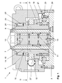
- FIG. 1 an embodiment of a lifting device 1 according to the invention is shown.
- the lifting device 1 has a bottom plate 3, which can rest on a base surface and with which a housing 5 and a dome 7, which extends perpendicularly from the bottom plate 3, are screwed.
- the dome 7 is surrounded by a lifting spindle 9, which is designed as a hollow cylinder.
- a linear guide is provided which comprises four guide rails 10 screwed to the dome 7, which are distributed uniformly over the circumference of the dome 7 and each extend over the entire axial length of the dome 7.
- guide rails 10 run in the axial direction of the mandrel 7 movable carriage 11, which are fixedly connected to the inner surface of the cylindrical lifting spindle 9.
- the dome 7 has four projections 12 which are arranged between the guide rails 10.
- the projections 12 of the dome 7 is additionally reinforced, so that its torsional stiffness further increases.
- the lifting spindle 9 has at the upper end threaded holes 13 through which it can be bolted to a lifting object.
- a thread 14 is provided, which engages with a thread 15 that is formed on the inner surface of a threaded bushing 16.
- the threaded bush 16 is also formed as a hollow cylinder and surrounds the lifting spindle 9.
- the threaded bushing 16 has an annular projection 17, with which a threaded bush 16 annularly surrounding worm wheel 18 is screwed.
- the projection 17 of the threaded bush 16 with the upper inner ring 19 and the lower inner ring 20 of a known from the prior art axial-radial bearing 21 is screwed.
- the relative to the upper and lower inner ring 19, 20 rotatable outer ring 23 of the axial-radial bearing 21 is in turn screwed to the bottom plate 3, so that the threaded bushing 16 relative to the bottom plate 3 and the housing 5 is rotatably supported but immovable in the axial direction.
- a bearing 24 is provided at the upper portion of the threaded bushing 16, the outer ring 25 are received in the housing 5 and the inner ring 26 in the threaded bushing 16, whereby the threaded bushing 16 is also secured radially.
- the lifting spindle 9 and the threaded bushing 16 arranged worm shaft 27 is provided, which received at one end in a bearing assembly 28 and provided at the other end with a likewise provided in the housing 5, axially pluggable Shaft coupling 29 is coupled (s. Fig. 2 ).
- the worm shaft 27 has a threaded portion 30, wherein the worm shaft 27 is arranged such that the threaded portion 30 engages with the screwed onto the projection 17 of the threaded bushing 16 worm wheel 18. Therefore, rotation of the worm shaft 27 causes rotation of the threaded bushing 16.
- the shaft coupling 29 is in turn connected to the output shaft 31 of a transmission, in this case an angular gear 32, whose input is connected to a drive motor 33.
- a transmission in this case an angular gear 32, whose input is connected to a drive motor 33.
- the transmission and in particular the angle gear 32 used here is designed such that the rotational speed of the output shaft 31 is reduced relative to that of the drive motor 33.
- a sensor 34 is mounted, which can engage with a bolted to the lifting spindle 9 via the threaded holes 13 object to directly detect the distance to which the object is raised by means of the lifting device 1.
- the lifting device 1 operates as follows. When the output shaft of the drive motor 33 rotates, the rotational speed is reduced by the bevel gear 32, so that the output shaft 31 of the bevel gear 32 and the worm shaft 27 rotate at a reduced speed. In this case, the worm shaft 27, the worm wheel 18 and thus the threaded bushing 16 in rotation. The internal thread 15 of the threaded bush 16 engages with the external thread 14 on the outer surface of the lifting spindle 9, and since the lifting spindle 9 is secured against rotation by the dome 7 via the linear guide, but is axially movable, no rotation but a rectilinear movement of the lifting spindle 9 along romance 7 instead. The lifting spindle 9 is thus moved out of the housing 5 or back into it.
Landscapes
- Life Sciences & Earth Sciences (AREA)
- Engineering & Computer Science (AREA)
- Geology (AREA)
- Mechanical Engineering (AREA)
- Structural Engineering (AREA)
- Transmission Devices (AREA)
- Types And Forms Of Lifts (AREA)
- Spinning Or Twisting Of Yarns (AREA)
Applications Claiming Priority (1)
| Application Number | Priority Date | Filing Date | Title |
|---|---|---|---|
| DE102008062317A DE102008062317B3 (de) | 2008-12-08 | 2008-12-08 | Hebevorrichtung |
Publications (2)
| Publication Number | Publication Date |
|---|---|
| EP2194018A2 true EP2194018A2 (fr) | 2010-06-09 |
| EP2194018A3 EP2194018A3 (fr) | 2011-08-24 |
Family
ID=41396978
Family Applications (1)
| Application Number | Title | Priority Date | Filing Date |
|---|---|---|---|
| EP09176941A Withdrawn EP2194018A3 (fr) | 2008-12-08 | 2009-11-24 | Dispositif de levage |
Country Status (3)
| Country | Link |
|---|---|
| US (1) | US20100140573A1 (fr) |
| EP (1) | EP2194018A3 (fr) |
| DE (1) | DE102008062317B3 (fr) |
Families Citing this family (9)
| Publication number | Priority date | Publication date | Assignee | Title |
|---|---|---|---|---|
| EP2027162A1 (fr) * | 2006-01-23 | 2009-02-25 | Basf Se | Procede de fabrication de polymeres en solvant aqueux |
| RU2450024C2 (ru) * | 2006-03-31 | 2012-05-10 | Басф Се | Способ получения сополимеров акрилатов |
| WO2007128776A1 (fr) * | 2006-05-04 | 2007-11-15 | Basf Se | Polymères contenant des groupes acides neutralisés et leur utilisation |
| RU2441029C2 (ru) * | 2006-09-15 | 2012-01-27 | Басф Се | Амфолитный сополимер на основе кватернизованных азотсодержащих мономеров |
| TWI462867B (zh) * | 2011-05-12 | 2014-12-01 | Chi Jun Co Ltd | 升降裝置 |
| US9523347B2 (en) * | 2012-01-18 | 2016-12-20 | Gamesa Innovation & Technology, S.L. | Manual lifting tool for wind turbines |
| CN103758975A (zh) * | 2014-01-02 | 2014-04-30 | 洛阳理工学院 | 一种拖拉机动力输出试验台升降装置 |
| KR101884361B1 (ko) * | 2016-03-21 | 2018-08-02 | (주)엘더스티앤엘 | 콘크리트 도상 분기기 시공용 잭 |
| US11279602B2 (en) | 2019-12-12 | 2022-03-22 | Gilbert Engineering, LLC | Smart jack array |
Citations (3)
| Publication number | Priority date | Publication date | Assignee | Title |
|---|---|---|---|---|
| DE236726C (fr) | ||||
| DE2920133B1 (de) | 1979-05-18 | 1981-03-12 | Alfred 4072 Wickrath Bautz | Hubvorrichtung mit mindestens zwei gegeneinander teleskopartig ausfahrbaren Gewindespindeln |
| EP1473268A2 (fr) | 2003-04-28 | 2004-11-03 | Jürgen Zimmermann | Dispositif de levage |
Family Cites Families (20)
| Publication number | Priority date | Publication date | Assignee | Title |
|---|---|---|---|---|
| US569494A (en) * | 1896-10-13 | Extension and retraction device | ||
| US1379012A (en) * | 1920-03-24 | 1921-05-24 | Henry T Gibbard | Jack |
| US1441963A (en) * | 1920-11-20 | 1923-01-09 | Frederick J Bullis | Pushing apparatus |
| US1472388A (en) * | 1921-06-07 | 1923-10-30 | Ray C Finch | Screw jack |
| US1478111A (en) * | 1921-10-20 | 1923-12-18 | William C Farnum | Lifting jack |
| US1565878A (en) * | 1924-06-13 | 1925-12-15 | William E Pratt | Lifting jack |
| US1593217A (en) * | 1925-07-20 | 1926-07-20 | Auto Specialties Mfg Co | Double-lift jack |
| US1893728A (en) * | 1926-06-12 | 1933-01-10 | Auto Specialties Mfg Co | Jack |
| US1868478A (en) * | 1928-04-25 | 1932-07-19 | Walker Mfg Co | Lifting jack |
| US1849712A (en) * | 1928-08-11 | 1932-03-15 | Buda Co | Lifting jack |
| GB324605A (en) * | 1929-05-28 | 1930-01-30 | R T Shelley Ltd | A new or improved lifting jack |
| US1938404A (en) * | 1930-10-24 | 1933-12-05 | Auto Specialties Mfg Co | Jack |
| US2153888A (en) * | 1936-01-16 | 1939-04-11 | Herbert O Haferkorn | Double acting jack |
| US2183367A (en) * | 1938-08-23 | 1939-12-12 | Alfred De Cozen | Vehicle lifting jack |
| DE3617990C2 (de) * | 1986-05-28 | 1995-02-02 | Alfred Bautz | Hubvorrichtung mit zwei übereinander ausfahrbaren Gewindespindeln |
| IT1250121B (it) * | 1991-10-18 | 1995-03-30 | Enzo Maggiori | Martinetto telescopico elettrico. |
| EP0697366B1 (fr) * | 1994-05-26 | 1999-10-20 | Kanji Tomidokoro | Cric |
| US5664762A (en) * | 1996-09-11 | 1997-09-09 | Ausco Products, Inc. | Automotive screw jack |
| KR100401418B1 (ko) * | 2001-05-18 | 2003-10-22 | 제갈희 | 자동차 승강용 전동잭 |
| WO2005070737A1 (fr) * | 2004-01-13 | 2005-08-04 | Smith Fred P | Systeme d'asservissement electrique a couple limite permettant de deployer pour un vehicule un systeme de traction par chenille sur la neige |
-
2008
- 2008-12-08 DE DE102008062317A patent/DE102008062317B3/de not_active Expired - Fee Related
-
2009
- 2009-11-24 EP EP09176941A patent/EP2194018A3/fr not_active Withdrawn
- 2009-12-08 US US12/633,557 patent/US20100140573A1/en not_active Abandoned
Patent Citations (3)
| Publication number | Priority date | Publication date | Assignee | Title |
|---|---|---|---|---|
| DE236726C (fr) | ||||
| DE2920133B1 (de) | 1979-05-18 | 1981-03-12 | Alfred 4072 Wickrath Bautz | Hubvorrichtung mit mindestens zwei gegeneinander teleskopartig ausfahrbaren Gewindespindeln |
| EP1473268A2 (fr) | 2003-04-28 | 2004-11-03 | Jürgen Zimmermann | Dispositif de levage |
Also Published As
| Publication number | Publication date |
|---|---|
| EP2194018A3 (fr) | 2011-08-24 |
| DE102008062317B3 (de) | 2010-01-07 |
| US20100140573A1 (en) | 2010-06-10 |
Similar Documents
| Publication | Publication Date | Title |
|---|---|---|
| DE102008062317B3 (de) | Hebevorrichtung | |
| EP2951078B1 (fr) | Colonne de direction pour véhicule automobile | |
| DE102012102298B4 (de) | Linearaktuator und höhenverstellbarer Tisch | |
| DE102010000970C5 (de) | Höhenverstellbare Betätigungs-Einrichtung | |
| DE29919877U1 (de) | Elektromotorische Verstelleinrichtung | |
| EP3911475B1 (fr) | Dispositif de serrage | |
| DE102019103384A1 (de) | Planetenwälzgewindetrieb | |
| DE102019209930A1 (de) | Aktuator einer steer-by-wire-Lenkung mit einem Spindelantrieb sowie steer-by-wire-Lenkung | |
| DE69819826T2 (de) | Servosteuersystem | |
| DE102008060043B3 (de) | Spindelpresse | |
| DE202006008307U1 (de) | Hubvorrichtung mit Gewindestangen | |
| DE102006035915A1 (de) | Hubeinrichtung | |
| EP1820600B1 (fr) | Broche de perçage pour centre de traitement horizontal ou vertical dotée d'un entraînement intérieur à puissance dérivée | |
| DE102006032178B4 (de) | Vorrichtung zur Höhenverstellung des Aufbaus eines Kraftfahrzeugs | |
| EP0581982A1 (fr) | Porte pivotante pour passage de clients | |
| DE2920133C2 (de) | Hubvorrichtung mit mindestens zwei gegeneinander teleskopartig ausfahrbaren Gewindespindeln | |
| DE102005019906B3 (de) | Webmaschine mit lösbarer Verbindung zwischen einem Antriebsmittel und dem Kettbaum einer Webmaschine | |
| DE102017127937A1 (de) | Teleskopierbarer Linearaktuator und höhenverstellbarer Tisch | |
| DE29919215U1 (de) | Teleskopantriebseinheit | |
| EP1741664B1 (fr) | Actionneur pour le positionnement d'une charge | |
| WO2021052526A1 (fr) | Vis d'entraînement à roulement planétaire | |
| WO2018177469A1 (fr) | Dispositif de correction d'assiette d'une carrosserie de véhicule | |
| DE102021001554B3 (de) | Hubvorrichtung und Transportfahrzeug | |
| DE102017102318B4 (de) | Winkelgetriebe | |
| DE102009006482A1 (de) | Getriebe mit Gegenlager |
Legal Events
| Date | Code | Title | Description |
|---|---|---|---|
| PUAI | Public reference made under article 153(3) epc to a published international application that has entered the european phase |
Free format text: ORIGINAL CODE: 0009012 |
|
| AK | Designated contracting states |
Kind code of ref document: A2 Designated state(s): AT BE BG CH CY CZ DE DK EE ES FI FR GB GR HR HU IE IS IT LI LT LU LV MC MK MT NL NO PL PT RO SE SI SK SM TR |
|
| RAP1 | Party data changed (applicant data changed or rights of an application transferred) |
Owner name: HELMHOLTZ-ZENTRUM GEESTHACHT ZENTRUM FUER MATERIAL |
|
| PUAL | Search report despatched |
Free format text: ORIGINAL CODE: 0009013 |
|
| AK | Designated contracting states |
Kind code of ref document: A3 Designated state(s): AT BE BG CH CY CZ DE DK EE ES FI FR GB GR HR HU IE IS IT LI LT LU LV MC MK MT NL NO PL PT RO SE SI SK SM TR |
|
| RIC1 | Information provided on ipc code assigned before grant |
Ipc: B66F 3/08 20060101AFI20110721BHEP Ipc: B66F 3/18 20060101ALI20110721BHEP |
|
| STAA | Information on the status of an ep patent application or granted ep patent |
Free format text: STATUS: THE APPLICATION IS DEEMED TO BE WITHDRAWN |
|
| 18D | Application deemed to be withdrawn |
Effective date: 20120225 |