EP2194018A2 - Lifting device - Google Patents
Lifting device Download PDFInfo
- Publication number
- EP2194018A2 EP2194018A2 EP09176941A EP09176941A EP2194018A2 EP 2194018 A2 EP2194018 A2 EP 2194018A2 EP 09176941 A EP09176941 A EP 09176941A EP 09176941 A EP09176941 A EP 09176941A EP 2194018 A2 EP2194018 A2 EP 2194018A2
- Authority
- EP
- European Patent Office
- Prior art keywords
- lifting
- lifting spindle
- spindle
- dome
- lifting device
- Prior art date
- Legal status (The legal status is an assumption and is not a legal conclusion. Google has not performed a legal analysis and makes no representation as to the accuracy of the status listed.)
- Withdrawn
Links
Images


Classifications
-
- B—PERFORMING OPERATIONS; TRANSPORTING
- B66—HOISTING; LIFTING; HAULING
- B66F—HOISTING, LIFTING, HAULING OR PUSHING, NOT OTHERWISE PROVIDED FOR, e.g. DEVICES WHICH APPLY A LIFTING OR PUSHING FORCE DIRECTLY TO THE SURFACE OF A LOAD
- B66F3/00—Devices, e.g. jacks, adapted for uninterrupted lifting of loads
- B66F3/08—Devices, e.g. jacks, adapted for uninterrupted lifting of loads screw operated
- B66F3/18—Devices, e.g. jacks, adapted for uninterrupted lifting of loads screw operated actuated through worm gearings
Definitions
- the present invention relates to a lifting device with a housing, with a lifting spindle which is cylindrical and has on the outer surface an external thread, with a threaded bushing which surrounds the lifting spindle and having an internal thread, which is in engagement with the external thread, and with a Drive unit for rotating drive of the threaded bush, wherein the lifting spindle is slidably and non-rotatably supported in the housing in the axial direction thereof.
- a lifting device with two mutually telescopically movable threaded spindles known, wherein the outer threaded spindle is also rotated upon rotation of the inner threaded spindle in rotation. Both threaded spindles are moved simultaneously in the longitudinal direction.
- a lifting device with a hollow lifting spindle is known, which is guided by a nut and is moved out of a housing upon rotation of the nut.
- Lifting devices are known in which a massive lifting spindle in the axial direction rotatably, but slidably supported and surrounded by a threaded bushing which is driven in rotation. When the threaded bushing rotates, the lifting spindle is displaced in the axial direction, so that an attached to the end of the lifting spindle object can be raised or lowered.
- the length in the axial direction of the lifting spindle is determined by the length of the threaded bushing on the one hand and by the length of the guide elements arranged in the axial direction in front of and behind the threaded bush, which hold the lifting spindle axially displaceable but non-rotatable.
- the size is determined on the one hand by the length of the threaded bushing, which also determines the maximum stroke of the lifting device, and on the other by the axial length of the front and behind the threaded bushing arranged guide elements. This means that the stroke provided by the lifting device is reduced by the guide elements when the maximum size of the lifting device is fixed.
- the lifting spindle is designed as a hollow cylinder that a dome arranged inside the lifting spindle and rotatably connected to the housing and that the lifting spindle is rotatably mounted and axially displaceable on the dome.
- the dome is arranged in the interior of the lifting spindle, it is achieved that in a large stroke yet in comparison with the prior art, a more compact design is possible because no additional guide elements are required in the axial direction in front of and behind the lifting spindle are arranged, but these are provided in the interior of the hollow cylindrical lifting spindle.
- the drive unit on the one hand, has a worm wheel mounted on the threaded bushing and, on the other hand, a worm shaft engaged therewith, which in turn is rotationally driven.
- an axially pluggable shaft coupling is provided between the worm shaft and a further angular gear transmission, for example, an angular gear to damp torsional vibrations.
- guide rails are mounted on either the dome or the jackscrew, and there are further provided carriages running in the guide rails and fixed to the member which does not have the guide rails. In this way it can be realized that the lifting spindle is axially displaceable, but held non-rotatably on the dome.
- a plurality of guide rails can be distributed over the circumference of the dome, wherein the dome between the guide rails may have outwardly facing projections which serve to increase the torsional stiffness of the dome.
- the lifting spindle is axially displaceable but rotatably coupled to the dome
- the dome may have a circular cross-section and be provided with one or more axially extending raceways.
- the lifting spindle On the inner circumferential surface of the lifting spindle can then be mounted a socket through which the dome with the Runways extends, with balls held in the sleeve extending into the raceways, so that the sleeve does not rotate relative to the Dom but can be moved axially.
- the dome is designed as a toothed shaft and the lifting spindle is firmly connected internally with a sleeve having a correspondingly formed the toothing bore, so that in this case, the lifting spindle against rotation but slidably with the Dom is coupled.
- the connection between the dome and the lifting spindle via a so-called polygonal connection the dome thus has a deviating from a circular symmetrical shape cross-section and the bushing attached to the lifting spindle is provided with a corresponding bore.
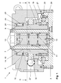
- FIG. 1 an embodiment of a lifting device 1 according to the invention is shown.
- the lifting device 1 has a bottom plate 3, which can rest on a base surface and with which a housing 5 and a dome 7, which extends perpendicularly from the bottom plate 3, are screwed.
- the dome 7 is surrounded by a lifting spindle 9, which is designed as a hollow cylinder.
- a linear guide is provided which comprises four guide rails 10 screwed to the dome 7, which are distributed uniformly over the circumference of the dome 7 and each extend over the entire axial length of the dome 7.
- guide rails 10 run in the axial direction of the mandrel 7 movable carriage 11, which are fixedly connected to the inner surface of the cylindrical lifting spindle 9.
- the dome 7 has four projections 12 which are arranged between the guide rails 10.
- the projections 12 of the dome 7 is additionally reinforced, so that its torsional stiffness further increases.
- the lifting spindle 9 has at the upper end threaded holes 13 through which it can be bolted to a lifting object.
- a thread 14 is provided, which engages with a thread 15 that is formed on the inner surface of a threaded bushing 16.
- the threaded bush 16 is also formed as a hollow cylinder and surrounds the lifting spindle 9.
- the threaded bushing 16 has an annular projection 17, with which a threaded bush 16 annularly surrounding worm wheel 18 is screwed.
- the projection 17 of the threaded bush 16 with the upper inner ring 19 and the lower inner ring 20 of a known from the prior art axial-radial bearing 21 is screwed.
- the relative to the upper and lower inner ring 19, 20 rotatable outer ring 23 of the axial-radial bearing 21 is in turn screwed to the bottom plate 3, so that the threaded bushing 16 relative to the bottom plate 3 and the housing 5 is rotatably supported but immovable in the axial direction.
- a bearing 24 is provided at the upper portion of the threaded bushing 16, the outer ring 25 are received in the housing 5 and the inner ring 26 in the threaded bushing 16, whereby the threaded bushing 16 is also secured radially.
- the lifting spindle 9 and the threaded bushing 16 arranged worm shaft 27 is provided, which received at one end in a bearing assembly 28 and provided at the other end with a likewise provided in the housing 5, axially pluggable Shaft coupling 29 is coupled (s. Fig. 2 ).
- the worm shaft 27 has a threaded portion 30, wherein the worm shaft 27 is arranged such that the threaded portion 30 engages with the screwed onto the projection 17 of the threaded bushing 16 worm wheel 18. Therefore, rotation of the worm shaft 27 causes rotation of the threaded bushing 16.
- the shaft coupling 29 is in turn connected to the output shaft 31 of a transmission, in this case an angular gear 32, whose input is connected to a drive motor 33.
- a transmission in this case an angular gear 32, whose input is connected to a drive motor 33.
- the transmission and in particular the angle gear 32 used here is designed such that the rotational speed of the output shaft 31 is reduced relative to that of the drive motor 33.
- a sensor 34 is mounted, which can engage with a bolted to the lifting spindle 9 via the threaded holes 13 object to directly detect the distance to which the object is raised by means of the lifting device 1.
- the lifting device 1 operates as follows. When the output shaft of the drive motor 33 rotates, the rotational speed is reduced by the bevel gear 32, so that the output shaft 31 of the bevel gear 32 and the worm shaft 27 rotate at a reduced speed. In this case, the worm shaft 27, the worm wheel 18 and thus the threaded bushing 16 in rotation. The internal thread 15 of the threaded bush 16 engages with the external thread 14 on the outer surface of the lifting spindle 9, and since the lifting spindle 9 is secured against rotation by the dome 7 via the linear guide, but is axially movable, no rotation but a rectilinear movement of the lifting spindle 9 along romance 7 instead. The lifting spindle 9 is thus moved out of the housing 5 or back into it.
Landscapes
- Life Sciences & Earth Sciences (AREA)
- Engineering & Computer Science (AREA)
- Geology (AREA)
- Mechanical Engineering (AREA)
- Structural Engineering (AREA)
- Transmission Devices (AREA)
- Types And Forms Of Lifts (AREA)
- Spinning Or Twisting Of Yarns (AREA)
Abstract
Description
Die vorliegende Erfindung betrifft eine Hebevorrichtung mit einem Gehäuse, mit einer Hubspindel, die zylindrisch ausgebildet ist und auf der Außenfläche ein Außengewinde aufweist, mit einer Gewindebuchse, die die Hubspindel umgibt und ein Innengewinde aufweist, das mit dem Außengewinde in Eingriff steht, und mit einer Antriebseinheit zum drehenden Antrieb der Gewindebuchse, wobei die Hubspindel in deren axialer Richtung verschiebbar und unverdrehbar in dem Gehäuse gehaltert ist.The present invention relates to a lifting device with a housing, with a lifting spindle which is cylindrical and has on the outer surface an external thread, with a threaded bushing which surrounds the lifting spindle and having an internal thread, which is in engagement with the external thread, and with a Drive unit for rotating drive of the threaded bush, wherein the lifting spindle is slidably and non-rotatably supported in the housing in the axial direction thereof.
Aus der
Aus dem Stand der Technik, wie beispielsweise der
Soll eine derartige Hebevorrichtung dazu eingesetzt werden, innerhalb eines Raumes, der eine vorgegebene Raumhöhe hat, einen Gegenstand positionsgenau anzuheben, wobei die Höhe des Gegenstandes in der gleichen Größenordnung wie die Raumhöhe ist, ergibt sich das Problem, dass eine dafür verwendete Hebevorrichtung eine möglichst kleine Baugröße in axialer Länge der Hubspindel haben muss.If such a lifting device is to be used to raise an object within a space having a predetermined height, with the height of the object being of the same order of magnitude as the height of the room, the problem arises that a lifting device used for this purpose has the smallest possible height Size in axial length of the lifting spindle must have.
Bei den aus dem Stand der Technik bekannten Hebevorrichtungen wird die Baugröße zum einen durch die Länge der Gewindebuchse bestimmt, die gleichzeitig auch den maximalen Hub der Hebevorrichtung festlegt, und zum anderen durch die axiale Länge der vor und hinter der Gewindebuchse angeordneten Führungselemente. Dies bedeutet, dass durch die Führungselemente der durch die Hebevorrichtung bereitgestellte Hub reduziert wird, wenn die maximale Baugröße der Hebevorrichtung fest vorgegeben ist.In the lifting devices known from the prior art, the size is determined on the one hand by the length of the threaded bushing, which also determines the maximum stroke of the lifting device, and on the other by the axial length of the front and behind the threaded bushing arranged guide elements. This means that the stroke provided by the lifting device is reduced by the guide elements when the maximum size of the lifting device is fixed.
Ausgehend vom Stand der Technik ist es daher die Aufgabe der vorliegenden Erfindung, eine Hebevorrichtung bereitzustellen, die eine möglichst kurze Baulänge in axialer Richtung der Hubspindel aufweist.Based on the prior art, it is therefore the object of the present invention to provide a lifting device which has the shortest possible length in the axial direction of the lifting spindle.
Diese Aufgabe wird dadurch gelöst, dass die Hubspindel als Hohlzylinder ausgebildet ist, dass ein Dom im Inneren der Hubspindel angeordnet und drehfest mit dem Gehäuse verbunden ist und dass die Hubspindel drehfest und axial verschiebbar an dem Dom gehaltert ist.This object is achieved in that the lifting spindle is designed as a hollow cylinder that a dome arranged inside the lifting spindle and rotatably connected to the housing and that the lifting spindle is rotatably mounted and axially displaceable on the dome.
Dadurch, dass der Dom im Inneren der Hubspindel angeordnet ist, wird erreicht, dass bei einem großen Hub dennoch im Vergleich zum Stand der Technik eine kompaktere Bauweise möglich ist, da keine zusätzlichen Führungselemente mehr erforderlich sind, die in axialer Richtung vor und hinter der Hubspindel angeordnet sind, sondern diese im Inneren der hohlzylindrisch ausgebildeten Hubspindel vorgesehen sind.The fact that the dome is arranged in the interior of the lifting spindle, it is achieved that in a large stroke yet in comparison with the prior art, a more compact design is possible because no additional guide elements are required in the axial direction in front of and behind the lifting spindle are arranged, but these are provided in the interior of the hollow cylindrical lifting spindle.
In einer bevorzugten Ausführungsform weist die Antriebseinheit zum einen ein an der Gewindebuchse angebrachtes Schneckenrad auf und zum anderen eine damit in Eingriff stehende Schneckenwelle, die wiederum drehend angetrieben ist. Durch einen derartigen Aufbau kann ein vergleichsweise hohes Drehmoment auf die Gewindebuchse ausgeübt werden, so dass die Hebevorrichtung in der Lage ist, sehr große Lasten anzuheben.In a preferred embodiment, the drive unit, on the one hand, has a worm wheel mounted on the threaded bushing and, on the other hand, a worm shaft engaged therewith, which in turn is rotationally driven. By such a structure, a comparatively high torque can be exerted on the threaded bush, so that the lifting device is able to lift very large loads.
Dabei ist es besonders bevorzugt, wenn zwischen der Schneckenwelle und einem weiteren Winkelgetriebe Getriebe, beispielsweise einem Winkelgetriebe, eine axial steckbare Wellenkupplung vorgesehen ist, um Drehschwingungen zu dämpfen.It is particularly preferred if an axially pluggable shaft coupling is provided between the worm shaft and a further angular gear transmission, for example, an angular gear to damp torsional vibrations.
Zum Führen der Hubspindel durch den Dom sind in einer bevorzugten Ausführungsform Führungsschienen entweder an dem Dom oder der Hubspindel angebracht, und es sind des Weiteren Wagen vorgesehen, die in den Führungsschienen laufen und an dem Element befestigt sind, das nicht die Führungsschienen aufweist. Auf diese Weise kann realisiert werden, dass die Hubspindel axial verschiebbar, aber unverdrehbar am Dom gehaltert ist.For guiding the lifting spindle through the dome, in a preferred embodiment, guide rails are mounted on either the dome or the jackscrew, and there are further provided carriages running in the guide rails and fixed to the member which does not have the guide rails. In this way it can be realized that the lifting spindle is axially displaceable, but held non-rotatably on the dome.
Dabei können in weiter bevorzugter Weise mehrere Führungsschienen über den Umfang des Doms verteilt sein, wobei der Dom zwischen den Führungsschienen nach außen weisende Vorsprünge aufweisen kann, die dazu dienen, die Torsionssteifigkeit des Domes zu erhöhen.In this case, in a further preferred manner, a plurality of guide rails can be distributed over the circumference of the dome, wherein the dome between the guide rails may have outwardly facing projections which serve to increase the torsional stiffness of the dome.
Als Alternative zu der Anordnung mit Führungsschienen und Laufwagen, mit der erreicht wird, dass die Hubspindel axial verschiebbar aber drehfest mit dem Dom gekoppelt ist, sind auch andere Anordnungen denkbar. Beispielsweise kann der Dom einen kreisförmigen Querschnitt aufweisen und mit einer oder mehreren, in axialer Richtung verlaufenden Laufbahnen versehen sein. An der inneren Umfangsfläche der Hubspindel kann dann eine Buchse angebracht sein, durch die sich der Dom mit den Laufbahnen erstreckt, wobei sich in der Buchse gehaltene Kugeln in die Laufbahnen erstrecken, so dass die Buchse sich nicht gegenüber dem Dom verdrehen aber axial verschieben lässt.As an alternative to the arrangement with guide rails and carriage, with which it is achieved that the lifting spindle is axially displaceable but rotatably coupled to the dome, other arrangements are conceivable. For example, the dome may have a circular cross-section and be provided with one or more axially extending raceways. On the inner circumferential surface of the lifting spindle can then be mounted a socket through which the dome with the Runways extends, with balls held in the sleeve extending into the raceways, so that the sleeve does not rotate relative to the Dom but can be moved axially.
Alternativ zu dieser Kugelbüchsenführung ist es auch denkbar, dass der Dom als eine Zahnwelle ausgestaltet ist und die Hubspindel im Inneren mit einer Buchse fest verbunden ist, die eine entsprechend der Verzahnung ausgebildete Bohrung aufweist, sodass auch in diesem Fall die Hubspindel verdrehsicher aber verschiebbar mit dem Dom gekoppelt ist.As an alternative to this ball bushing, it is also conceivable that the dome is designed as a toothed shaft and the lifting spindle is firmly connected internally with a sleeve having a correspondingly formed the toothing bore, so that in this case, the lifting spindle against rotation but slidably with the Dom is coupled.
Schließlich ist es auch denkbar, dass die Verbindung zwischen Dom und Hubspindel über eine sogenannte Polygonverbindung erfolgt, der Dom also einen von einer kreissymmetrischen Form abweichenden Querschnitt aufweist und die an der Hubspindel befestigte Buchse mit einer entsprechenden Bohrung versehen ist.Finally, it is also conceivable that the connection between the dome and the lifting spindle via a so-called polygonal connection, the dome thus has a deviating from a circular symmetrical shape cross-section and the bushing attached to the lifting spindle is provided with a corresponding bore.
Die vorliegende Erfindung wird im Folgenden anhand einer ein Ausführungsbeispiel darstellenden Zeichnung erläutert. Die Zeichnung zeigt in
- Fig. 1
- einen Schnitt in axialer Richtung eines Ausführungsbeispiels einer erfindungsgemäßen Hebevorrichtung,
- Fig. 2
- einen Schnitt entlang der Linie II-II aus
Fig. 1 , - Fig. 3
- eine erste perspektivische Darstellung des Ausführungsbeispiels aus
Fig. 1 und - Fig. 4
- eine zweite perspektivische Darstellung des Ausführungsbeispiels aus
Fig. 1 .
- Fig. 1
- a section in the axial direction of an embodiment of a lifting device according to the invention,
- Fig. 2
- a section along the line II-II
Fig. 1 . - Fig. 3
- a first perspective view of the embodiment
Fig. 1 and - Fig. 4
- a second perspective view of the embodiment
Fig. 1 ,
In
Der Dom 7 ist von einer Hubspindel 9 umgeben, die als Hohlzylinder ausgebildet ist. An dem Dom 7 ist eine Linearführung vorgesehen, die vier mit dem Dom 7 verschraubte Führungsschienen 10 umfasst, die gleichmäßig über den Umfang des Doms 7 verteilt sind und sich jeweils über die gesamte axiale Länge des Doms 7 erstrecken. In den Führungsschienen 10 laufen in axialer Richtung des Doms 7 bewegliche Laufwagen 11, die fest mit der Innenfläche der zylindrischen Hubspindel 9 verbunden sind. Durch diese Anordnung aus Führungsschienen 10 und Laufwagen 11 wird die Hubspindel 9 axial verschiebbar aber drehfest mit dem Dom 7 gekoppelt.The
Es ist allerdings auch denkbar, dass die Führungsschienen 10 an der Hubspindel 9 angebracht sind, während die Wagen 11 an dem Dom 7 befestigt sind.However, it is also conceivable that the
Neben der hier beschriebenen Kopplung von Dom 7 und Hubspindel 9 über eine Laufwagen-Anordnung ist es auch denkbar, dass die Kopplung nach dem Prinzip der Kugelbüchsenführung oder der Polygonverbindung erfolgt. In jedem Fall muss sichergestellt werden, dass die die Hubspindel 9 in axialer Richtung verschiebbar aber unverdrehbar mit dem Dom 7 gekoppelt ist.In addition to the coupling of Dom 7 and lifting
Außerdem weist der Dom 7 vier Vorsprünge 12 auf, die zwischen den Führungsschienen 10 angeordnet sind. Durch die Vorsprünge 12 wird der Dom 7 zusätzlich verstärkt, sodass sich dessen Torsionssteifigkeit weiter erhöht.In addition, the
Die Hubspindel 9 weist am oberen Ende Gewindebohrungen 13 auf, über die sie mit einem zuhebenden Gegenstand verschraubt werden kann. Auf der Außenfläche der Hubspindel 9 ist ein Gewinde 14 vorgesehen, das mit einem Gewinde 15 eingreift, dass an der Innenfläche einer Gewindebuchse 16 ausgebildet ist.The
Die Gewindebuchse 16 ist ebenfalls als Hohlzylinder ausgebildet und umgibt die Hubspindel 9. Außerdem weist die Gewindebuchse 16 einen ringförmigen Vorsprung 17 auf, mit dem ein die Gewindebuchse 16 ringförmig umgebendes Schneckenrad 18 verschraubt ist.The threaded
Außerdem ist der Vorsprung 17 der Gewindebuchse 16 mit dem oberen Innenring 19 und dem unteren Innenring 20 eines aus dem Stand der Technik bekannten Axial-Radiallagers 21 verschraubt. Der gegenüber dem oberen und unteren Innenring 19, 20 drehbare äußere Ring 23 des Axial-Radiallagers 21 ist wiederum mit der Bodenplatte 3 verschraubt, sodass die Gewindebuchse 16 gegenüber der Bodenplatte 3 und dem Gehäuse 5 drehbar aber in axialer Richtung unverschieblich gehaltert ist.In addition, the
Außerdem ist am oberen Bereich der der Gewindebuchse 16 ein Lager 24 vorgesehen, dessen äußerer Ring 25 im Gehäuse 5 und dessen innerer Ring 26 in der Gewindebuchse 16 aufgenommen sind, wodurch die Gewindebuchse 16 ebenfalls radial gesichert wird.In addition, a
Im Gehäuse 5 ist ferner eine sich senkrecht zur axialen Richtung des Doms 7, der Hubspindel 9 und der Gewindebuchse 16 angeordnete Schneckenwelle 27 vorgesehen, die an einem Ende in einer Lageranordnung 28 aufgenommen und am anderen Ende mit einer ebenfalls im Gehäuse 5 vorgesehenen, axial steckbaren Wellenkupplung 29 gekoppelt ist (s.
Durch die Verwendung eines Aufbaus aus einem Schneckenrad 18 und einer Schneckenwelle 27 kann ein sehr hohes Drehmoment auf die Gewindebuchse 16 ausgeübt werden, sodass mit der Hebevorrichtung 1 hohe Lasten angehoben werden können.By using a structure of a
Die Wellenkupplung 29 ist wiederum mit der Ausgangswelle 31 eines Getriebes, in diesem Fall eines Winkelgetriebes 32 verbunden, dessen Eingang mit einem Antriebsmotor 33 verbunden ist. Dabei ist das Getriebe und insbesondere das hier verwendete Winkelgetriebe 32 derart ausgebildet, dass die Drehzahl der Ausgangswelle 31 gegenüber der des Antriebsmotors 33 reduziert wird.The
Damit bilden das Schneckenrad 18, die Schneckenwelle 27, die Wellenkupplung 29, das Winkelgetriebe 32 und der Antriebsmotor 33 eine Antriebseinheit zum drehenden Antrieb der Gewindebuchse 16. Dabei wird durch die Wellenkupplung 29 erreicht, dass die Ausgangswelle 31 und die Schneckenwelle 27 nicht vollständig exakt zueinander ausgerichtet sind müssen. Außerdem liegt kein direkter Formschluss zwischen der Gewindebuchse 16 und dem Antriebsmotor 33 vor, sodass Drehschwingungen gedämpft werden.Thus, the
Schließlich ist außen am Gehäuse 5 ein Sensor 34 angebracht, der mit einem mit der Hubspindel 9 über die Gewindebohrungen 13 verschraubten Gegenstand eingreifen kann, um die Wegstrecke direkt zu erfassen, um die der Gegenstand mittels der Hebevorrichtung 1 angehoben wird.Finally, outside the
Die Hebevorrichtung 1 arbeitet wie folgt. Wenn die Ausgangswelle des Antriebsmotors 33 dreht, wird die Drehzahl von dem Winkelgetriebe 32 reduziert, sodass die Ausgangswelle 31 des Winkelgetriebes 32 sowie die Schneckenwelle 27 mit verminderter Drehzahl drehen. Dabei versetzt die Schneckenwelle 27 das Schneckenrad 18 und damit die Gewindebuchse 16 in Rotation. Das Innengewinde 15 der Gewindebuchse 16 greift mit dem Außengewinde 14 auf der Außenfläche der Hubspindel 9 ein, und da die Hubspindel 9 durch den Dom 7 über die Linearführung verdrehsicher ist, jedoch axial beweglich ist, findet keine Rotation sondern eine geradlinige Bewegung der Hubspindel 9 entlang des Doms 7 statt. Die Hubspindel 9 wird also aus dem Gehäuse 5 heraus oder wieder hinein bewegt.The lifting device 1 operates as follows. When the output shaft of the
Durch die Anordnung des Doms 7 mit Linearführung im Inneren der Hubspindel 9 wird somit erreicht, dass bei einem großen Hub dennoch im Vergleich zum Stand der Technik eine kompaktere Bauweise möglich ist, da in axialer Richtung der Hubspindel 9 keine zusätzlichen Führungselemente erforderlich sind, sondern diese im Inneren der hohlzylindrisch ausgebildeten Hubspindel 9 angeordnet sind.Due to the arrangement of the
Claims (7)
mit einer Hubspindel (9), die zylindrisch ausgebildet ist und auf der Außenfläche ein Außengewinde (14) aufweist,
mit einer Gewindebuchse (16), die die Hubspindel (9) umgibt und ein Innengewinde (15) aufweist, das mit dem Außengewinde (14) in Eingriff steht, und
mit einer Antriebseinheit zum drehenden Antrieb der Gewindebuchse (16),
wobei die Hubspindel (9) in deren axialer Richtung verschiebbar und unverdrehbar in dem Gehäuse (5) gehaltert ist,
dadurch gekennzeichnet,
dass die Hubspindel (9) als Hohlzylinder ausgebildet ist,
dass ein Dom (7) im Inneren der Hubspindel (9) angeordnet und drehfest mit dem Gehäuse (5) verbunden ist und
dass die Hubspindel (9) drehfest und axial verschiebbar an dem Dom (7) gehaltert ist.Lifting device with a housing (5),
with a lifting spindle (9), which is cylindrical and has an outer thread (14) on the outer surface,
a threaded bushing (16) surrounding the lifting spindle (9) and having an internal thread (15) which engages with the external thread (14), and
with a drive unit for rotating drive of the threaded bushing (16),
the lifting spindle (9) being mounted displaceably and non-rotatably in the housing (5) in its axial direction,
characterized,
that the lifting spindle (9) is designed as a hollow cylinder,
that a dome (7) in the interior of the lifting spindle (9) is arranged and non-rotatably connected to the housing (5) and
that the lifting spindle (9) rotationally fixed and axially displaceable on the mandrel (7) is supported.
dass eine Schneckenwelle (27) vorgesehen ist, die mit dem Schneckenrad (18) eingreift und drehend angetrieben ist.Lifting device according to claim 1, characterized in that the threaded bushing (16) has a worm wheel (18) which surrounds the threaded bushing (16), and
that a worm shaft (27) is provided, which engages with the worm wheel (18) and is driven in rotation.
dass an der Innenfläche der Hubspindel (9) ein Laufwagen (11) befestigt ist, der verschiebbar in der Führungsschiene (10) geführt ist.Lifting device according to one of claims 1 to 3, characterized in that the dome (7) has a to the lifting spindle (9) facing guide rail (10) extending in the axial direction of the lifting spindle (9), and
that on the inner surface of the lifting spindle (9) a carriage (11) is fixed, which is displaceably guided in the guide rail (10).
dass an der zu der Hubspindel weisenden Fläche des Doms ein Laufwagen befestigt ist, der verschiebbar in der Führungsschiene geführt ist.Lifting device according to one of claims 1 to 3, characterized in that the lifting spindle (9) on the inner surface has a guide rail which extends in the axial direction of the lifting spindle, and
in that a carriage, which is displaceably guided in the guide rail, is fastened to the surface of the dome facing the lifting spindle.
Applications Claiming Priority (1)
| Application Number | Priority Date | Filing Date | Title |
|---|---|---|---|
| DE102008062317A DE102008062317B3 (en) | 2008-12-08 | 2008-12-08 | Device for lifting large loads within ceiling, has lifting spindle that is displaceably and non-rotatably held in axial direction in housing, and dome that is torque-proofly connected with housing |
Publications (2)
| Publication Number | Publication Date |
|---|---|
| EP2194018A2 true EP2194018A2 (en) | 2010-06-09 |
| EP2194018A3 EP2194018A3 (en) | 2011-08-24 |
Family
ID=41396978
Family Applications (1)
| Application Number | Title | Priority Date | Filing Date |
|---|---|---|---|
| EP09176941A Withdrawn EP2194018A3 (en) | 2008-12-08 | 2009-11-24 | Lifting device |
Country Status (3)
| Country | Link |
|---|---|
| US (1) | US20100140573A1 (en) |
| EP (1) | EP2194018A3 (en) |
| DE (1) | DE102008062317B3 (en) |
Families Citing this family (9)
| Publication number | Priority date | Publication date | Assignee | Title |
|---|---|---|---|---|
| US20090010865A1 (en) * | 2006-01-23 | 2009-01-08 | Basf Se | Process for Preparing Polymers in Aqueous Solvents |
| JP5302882B2 (en) * | 2006-03-31 | 2013-10-02 | ビーエーエスエフ ソシエタス・ヨーロピア | Method for producing acrylate copolymer |
| CA2651094A1 (en) * | 2006-05-04 | 2007-11-15 | Basf Se | Neutralized acid group-containing polymers and the use thereof |
| US8303943B2 (en) * | 2006-09-15 | 2012-11-06 | Basf Se | Ampholytic copolymer based on quaternized nitrogen-containing monomers |
| TWI462867B (en) * | 2011-05-12 | 2014-12-01 | Chi Jun Co Ltd | Lifting device |
| US9523347B2 (en) * | 2012-01-18 | 2016-12-20 | Gamesa Innovation & Technology, S.L. | Manual lifting tool for wind turbines |
| CN103758975A (en) * | 2014-01-02 | 2014-04-30 | 洛阳理工学院 | Tractor power output testing table lifting device |
| KR101884361B1 (en) * | 2016-03-21 | 2018-08-02 | (주)엘더스티앤엘 | A jack for constructing concrete ballast turnout |
| US11279602B2 (en) | 2019-12-12 | 2022-03-22 | Gilbert Engineering, LLC | Smart jack array |
Citations (3)
| Publication number | Priority date | Publication date | Assignee | Title |
|---|---|---|---|---|
| DE236726C (en) | ||||
| DE2920133B1 (en) | 1979-05-18 | 1981-03-12 | Alfred 4072 Wickrath Bautz | Lifting device with at least two threaded spindles that can be telescopically extended |
| EP1473268A2 (en) | 2003-04-28 | 2004-11-03 | Jürgen Zimmermann | lifting device |
Family Cites Families (20)
| Publication number | Priority date | Publication date | Assignee | Title |
|---|---|---|---|---|
| US569494A (en) * | 1896-10-13 | Extension and retraction device | ||
| US1379012A (en) * | 1920-03-24 | 1921-05-24 | Henry T Gibbard | Jack |
| US1441963A (en) * | 1920-11-20 | 1923-01-09 | Frederick J Bullis | Pushing apparatus |
| US1472388A (en) * | 1921-06-07 | 1923-10-30 | Ray C Finch | Screw jack |
| US1478111A (en) * | 1921-10-20 | 1923-12-18 | William C Farnum | Lifting jack |
| US1565878A (en) * | 1924-06-13 | 1925-12-15 | William E Pratt | Lifting jack |
| US1593217A (en) * | 1925-07-20 | 1926-07-20 | Auto Specialties Mfg Co | Double-lift jack |
| US1893728A (en) * | 1926-06-12 | 1933-01-10 | Auto Specialties Mfg Co | Jack |
| US1868478A (en) * | 1928-04-25 | 1932-07-19 | Walker Mfg Co | Lifting jack |
| US1849712A (en) * | 1928-08-11 | 1932-03-15 | Buda Co | Lifting jack |
| GB324605A (en) * | 1929-05-28 | 1930-01-30 | R T Shelley Ltd | A new or improved lifting jack |
| US1938404A (en) * | 1930-10-24 | 1933-12-05 | Auto Specialties Mfg Co | Jack |
| US2153888A (en) * | 1936-01-16 | 1939-04-11 | Herbert O Haferkorn | Double acting jack |
| US2183367A (en) * | 1938-08-23 | 1939-12-12 | Alfred De Cozen | Vehicle lifting jack |
| DE3617990C2 (en) * | 1986-05-28 | 1995-02-02 | Alfred Bautz | Lifting device with two extendable threaded spindles |
| IT1250121B (en) * | 1991-10-18 | 1995-03-30 | Enzo Maggiori | ELECTRIC TELESCOPIC JACK. |
| DE69512849T2 (en) * | 1994-05-26 | 2000-06-15 | Kanji Tomidokoro | Jack |
| US5664762A (en) * | 1996-09-11 | 1997-09-09 | Ausco Products, Inc. | Automotive screw jack |
| KR100401418B1 (en) * | 2001-05-18 | 2003-10-22 | 제갈희 | Jack operated by electric for automobiles |
| WO2005070737A1 (en) * | 2004-01-13 | 2005-08-04 | Smith Fred P | Torque-limited electric servo system for deploying a vehicle snow chain traction system |
-
2008
- 2008-12-08 DE DE102008062317A patent/DE102008062317B3/en not_active Expired - Fee Related
-
2009
- 2009-11-24 EP EP09176941A patent/EP2194018A3/en not_active Withdrawn
- 2009-12-08 US US12/633,557 patent/US20100140573A1/en not_active Abandoned
Patent Citations (3)
| Publication number | Priority date | Publication date | Assignee | Title |
|---|---|---|---|---|
| DE236726C (en) | ||||
| DE2920133B1 (en) | 1979-05-18 | 1981-03-12 | Alfred 4072 Wickrath Bautz | Lifting device with at least two threaded spindles that can be telescopically extended |
| EP1473268A2 (en) | 2003-04-28 | 2004-11-03 | Jürgen Zimmermann | lifting device |
Also Published As
| Publication number | Publication date |
|---|---|
| DE102008062317B3 (en) | 2010-01-07 |
| EP2194018A3 (en) | 2011-08-24 |
| US20100140573A1 (en) | 2010-06-10 |
Similar Documents
| Publication | Publication Date | Title |
|---|---|---|
| DE102008062317B3 (en) | Device for lifting large loads within ceiling, has lifting spindle that is displaceably and non-rotatably held in axial direction in housing, and dome that is torque-proofly connected with housing | |
| EP2951078B1 (en) | Steering column for a motor vehicle | |
| DE102012102298B4 (en) | Linear actuator and height-adjustable table | |
| DE102010000970C5 (en) | Height-adjustable actuation device | |
| DE29919877U1 (en) | Electromotive adjustment device | |
| EP3911475B1 (en) | Clamping device | |
| DE102019103384A1 (en) | Planetary screw drive | |
| DE102019209930A1 (en) | Actuator of a steer-by-wire steering with a spindle drive as well as steer-by-wire steering | |
| DE69819826T2 (en) | POWER CONTROL SYSTEM | |
| DE102008060043B3 (en) | screw press | |
| DE202006008307U1 (en) | Lifting device, especially for electrical table or bed, has parallel double threaded rods, displacement units, drive device, transfer device connected to first displacement unit, telescopic tubes, second transfer device with rotary sleeve | |
| DE102006035915A1 (en) | lifting device | |
| EP1820600B1 (en) | Drill spindle for horizontal or vertical machining centre with an inner branched drive | |
| DE102006032178B4 (en) | Device for height adjustment of the construction of a motor vehicle | |
| EP0581982A1 (en) | Pivoting gate for clients' passage | |
| DE2920133C2 (en) | Lifting device with at least two mutually telescoping threaded spindles | |
| DE102005019906B3 (en) | Loom with releasable coupling between drive and warp beam, based on indentations in supporting wall through which screws can pass so that driver is screwable to or unscrewable from warp beam flange | |
| DE102017127937A1 (en) | Telescopic linear actuator and height-adjustable table | |
| DE29919215U1 (en) | Telescopic drive unit | |
| EP1741664B1 (en) | Actuator for positioning a load | |
| WO2021052526A1 (en) | Planetary roller screw drive | |
| WO2018177469A1 (en) | Device for adjusting the height of a vehicle body | |
| DE102021001554B3 (en) | lifting device and transport vehicle | |
| DE102017102318B4 (en) | bevel gear | |
| DE102009006482A1 (en) | Gear e.g. coaxial gear, has bearing stump formed at bevel or belt pulley and supported in counter bearing in rotatable manner, where bearing is screwed with fastening flange of gear and positioned coaxially to rotational axis of shaft |
Legal Events
| Date | Code | Title | Description |
|---|---|---|---|
| PUAI | Public reference made under article 153(3) epc to a published international application that has entered the european phase |
Free format text: ORIGINAL CODE: 0009012 |
|
| AK | Designated contracting states |
Kind code of ref document: A2 Designated state(s): AT BE BG CH CY CZ DE DK EE ES FI FR GB GR HR HU IE IS IT LI LT LU LV MC MK MT NL NO PL PT RO SE SI SK SM TR |
|
| RAP1 | Party data changed (applicant data changed or rights of an application transferred) |
Owner name: HELMHOLTZ-ZENTRUM GEESTHACHT ZENTRUM FUER MATERIAL |
|
| PUAL | Search report despatched |
Free format text: ORIGINAL CODE: 0009013 |
|
| AK | Designated contracting states |
Kind code of ref document: A3 Designated state(s): AT BE BG CH CY CZ DE DK EE ES FI FR GB GR HR HU IE IS IT LI LT LU LV MC MK MT NL NO PL PT RO SE SI SK SM TR |
|
| RIC1 | Information provided on ipc code assigned before grant |
Ipc: B66F 3/08 20060101AFI20110721BHEP Ipc: B66F 3/18 20060101ALI20110721BHEP |
|
| STAA | Information on the status of an ep patent application or granted ep patent |
Free format text: STATUS: THE APPLICATION IS DEEMED TO BE WITHDRAWN |
|
| 18D | Application deemed to be withdrawn |
Effective date: 20120225 |