EP2193100B1 - pH gradients controlled by electrolysis, and their use in isoelectric focusing - Google Patents
pH gradients controlled by electrolysis, and their use in isoelectric focusing Download PDFInfo
- Publication number
- EP2193100B1 EP2193100B1 EP08789831.8A EP08789831A EP2193100B1 EP 2193100 B1 EP2193100 B1 EP 2193100B1 EP 08789831 A EP08789831 A EP 08789831A EP 2193100 B1 EP2193100 B1 EP 2193100B1
- Authority
- EP
- European Patent Office
- Prior art keywords
- volume
- proton concentration
- environment
- proton
- counter electrode
- Prior art date
- Legal status (The legal status is an assumption and is not a legal conclusion. Google has not performed a legal analysis and makes no representation as to the accuracy of the status listed.)
- Not-in-force
Links
- 238000001155 isoelectric focusing Methods 0.000 title claims description 50
- 238000005868 electrolysis reaction Methods 0.000 title claims description 42
- 238000012876 topography Methods 0.000 claims description 98
- 239000003792 electrolyte Substances 0.000 claims description 32
- 150000002500 ions Chemical class 0.000 claims description 18
- 238000000034 method Methods 0.000 claims description 16
- 230000008859 change Effects 0.000 claims description 15
- 239000012530 fluid Substances 0.000 claims description 14
- 230000004888 barrier function Effects 0.000 claims description 9
- 238000004891 communication Methods 0.000 claims description 5
- 238000004519 manufacturing process Methods 0.000 claims description 4
- 230000004044 response Effects 0.000 claims description 4
- 238000012544 monitoring process Methods 0.000 claims description 3
- 239000000499 gel Substances 0.000 description 67
- 102000004169 proteins and genes Human genes 0.000 description 22
- 108090000623 proteins and genes Proteins 0.000 description 22
- 239000008151 electrolyte solution Substances 0.000 description 14
- 239000012528 membrane Substances 0.000 description 11
- 239000012491 analyte Substances 0.000 description 8
- 239000000203 mixture Substances 0.000 description 8
- BASFCYQUMIYNBI-UHFFFAOYSA-N platinum Chemical compound [Pt] BASFCYQUMIYNBI-UHFFFAOYSA-N 0.000 description 8
- XLYOFNOQVPJJNP-UHFFFAOYSA-N water Substances O XLYOFNOQVPJJNP-UHFFFAOYSA-N 0.000 description 8
- 238000001962 electrophoresis Methods 0.000 description 7
- -1 hydroxyl anions Chemical class 0.000 description 7
- 239000000463 material Substances 0.000 description 7
- 230000003247 decreasing effect Effects 0.000 description 6
- 238000004458 analytical method Methods 0.000 description 5
- 230000007423 decrease Effects 0.000 description 5
- 239000007788 liquid Substances 0.000 description 5
- 238000000926 separation method Methods 0.000 description 5
- 230000005684 electric field Effects 0.000 description 4
- 229910052697 platinum Inorganic materials 0.000 description 4
- 239000007832 Na2SO4 Substances 0.000 description 3
- PMZURENOXWZQFD-UHFFFAOYSA-L Sodium Sulfate Chemical compound [Na+].[Na+].[O-]S([O-])(=O)=O PMZURENOXWZQFD-UHFFFAOYSA-L 0.000 description 3
- 230000008901 benefit Effects 0.000 description 3
- 229910052938 sodium sulfate Inorganic materials 0.000 description 3
- 239000002033 PVDF binder Substances 0.000 description 2
- 229920005439 Perspex® Polymers 0.000 description 2
- 235000019647 acidic taste Nutrition 0.000 description 2
- 238000001816 cooling Methods 0.000 description 2
- 230000001419 dependent effect Effects 0.000 description 2
- 230000000694 effects Effects 0.000 description 2
- 125000000524 functional group Chemical group 0.000 description 2
- 239000011521 glass Substances 0.000 description 2
- 230000007062 hydrolysis Effects 0.000 description 2
- 238000006460 hydrolysis reaction Methods 0.000 description 2
- 230000037230 mobility Effects 0.000 description 2
- 239000007793 ph indicator Substances 0.000 description 2
- 229920003229 poly(methyl methacrylate) Polymers 0.000 description 2
- 229920002401 polyacrylamide Polymers 0.000 description 2
- 239000004417 polycarbonate Substances 0.000 description 2
- 229920000515 polycarbonate Polymers 0.000 description 2
- 229920002981 polyvinylidene fluoride Polymers 0.000 description 2
- 239000011148 porous material Substances 0.000 description 2
- 238000007873 sieving Methods 0.000 description 2
- 239000000243 solution Substances 0.000 description 2
- 229920000936 Agarose Polymers 0.000 description 1
- 229920002472 Starch Polymers 0.000 description 1
- 230000009471 action Effects 0.000 description 1
- 150000001450 anions Chemical class 0.000 description 1
- 230000003139 buffering effect Effects 0.000 description 1
- 150000001768 cations Chemical class 0.000 description 1
- 238000009792 diffusion process Methods 0.000 description 1
- 239000000017 hydrogel Substances 0.000 description 1
- 230000005012 migration Effects 0.000 description 1
- 238000013508 migration Methods 0.000 description 1
- 230000007935 neutral effect Effects 0.000 description 1
- 238000005192 partition Methods 0.000 description 1
- 230000002093 peripheral effect Effects 0.000 description 1
- 230000002572 peristaltic effect Effects 0.000 description 1
- 235000019698 starch Nutrition 0.000 description 1
- 239000008107 starch Substances 0.000 description 1
Images


Classifications
-
- C—CHEMISTRY; METALLURGY
- C02—TREATMENT OF WATER, WASTE WATER, SEWAGE, OR SLUDGE
- C02F—TREATMENT OF WATER, WASTE WATER, SEWAGE, OR SLUDGE
- C02F1/00—Treatment of water, waste water, or sewage
- C02F1/46—Treatment of water, waste water, or sewage by electrochemical methods
- C02F1/461—Treatment of water, waste water, or sewage by electrochemical methods by electrolysis
- C02F1/46104—Devices therefor; Their operating or servicing
- C02F1/46109—Electrodes
-
- G—PHYSICS
- G01—MEASURING; TESTING
- G01N—INVESTIGATING OR ANALYSING MATERIALS BY DETERMINING THEIR CHEMICAL OR PHYSICAL PROPERTIES
- G01N27/00—Investigating or analysing materials by the use of electric, electrochemical, or magnetic means
- G01N27/26—Investigating or analysing materials by the use of electric, electrochemical, or magnetic means by investigating electrochemical variables; by using electrolysis or electrophoresis
- G01N27/416—Systems
- G01N27/447—Systems using electrophoresis
- G01N27/44756—Apparatus specially adapted therefor
- G01N27/44795—Isoelectric focusing
-
- C—CHEMISTRY; METALLURGY
- C02—TREATMENT OF WATER, WASTE WATER, SEWAGE, OR SLUDGE
- C02F—TREATMENT OF WATER, WASTE WATER, SEWAGE, OR SLUDGE
- C02F1/00—Treatment of water, waste water, or sewage
- C02F1/66—Treatment of water, waste water, or sewage by neutralisation; pH adjustment
-
- G—PHYSICS
- G01—MEASURING; TESTING
- G01N—INVESTIGATING OR ANALYSING MATERIALS BY DETERMINING THEIR CHEMICAL OR PHYSICAL PROPERTIES
- G01N27/00—Investigating or analysing materials by the use of electric, electrochemical, or magnetic means
- G01N27/26—Investigating or analysing materials by the use of electric, electrochemical, or magnetic means by investigating electrochemical variables; by using electrolysis or electrophoresis
- G01N27/416—Systems
- G01N27/447—Systems using electrophoresis
- G01N27/44704—Details; Accessories
- G01N27/44717—Arrangements for investigating the separated zones, e.g. localising zones
-
- G—PHYSICS
- G01—MEASURING; TESTING
- G01N—INVESTIGATING OR ANALYSING MATERIALS BY DETERMINING THEIR CHEMICAL OR PHYSICAL PROPERTIES
- G01N27/00—Investigating or analysing materials by the use of electric, electrochemical, or magnetic means
- G01N27/26—Investigating or analysing materials by the use of electric, electrochemical, or magnetic means by investigating electrochemical variables; by using electrolysis or electrophoresis
- G01N27/416—Systems
- G01N27/447—Systems using electrophoresis
- G01N27/44704—Details; Accessories
- G01N27/44743—Introducing samples
-
- C—CHEMISTRY; METALLURGY
- C02—TREATMENT OF WATER, WASTE WATER, SEWAGE, OR SLUDGE
- C02F—TREATMENT OF WATER, WASTE WATER, SEWAGE, OR SLUDGE
- C02F1/00—Treatment of water, waste water, or sewage
- C02F1/46—Treatment of water, waste water, or sewage by electrochemical methods
- C02F1/461—Treatment of water, waste water, or sewage by electrochemical methods by electrolysis
- C02F1/46104—Devices therefor; Their operating or servicing
- C02F1/4618—Devices therefor; Their operating or servicing for producing "ionised" acidic or basic water
-
- C—CHEMISTRY; METALLURGY
- C02—TREATMENT OF WATER, WASTE WATER, SEWAGE, OR SLUDGE
- C02F—TREATMENT OF WATER, WASTE WATER, SEWAGE, OR SLUDGE
- C02F1/00—Treatment of water, waste water, or sewage
- C02F1/46—Treatment of water, waste water, or sewage by electrochemical methods
- C02F1/461—Treatment of water, waste water, or sewage by electrochemical methods by electrolysis
- C02F1/46104—Devices therefor; Their operating or servicing
- C02F1/46109—Electrodes
- C02F2001/46152—Electrodes characterised by the shape or form
- C02F2001/46157—Perforated or foraminous electrodes
-
- C—CHEMISTRY; METALLURGY
- C02—TREATMENT OF WATER, WASTE WATER, SEWAGE, OR SLUDGE
- C02F—TREATMENT OF WATER, WASTE WATER, SEWAGE, OR SLUDGE
- C02F2201/00—Apparatus for treatment of water, waste water or sewage
- C02F2201/46—Apparatus for electrochemical processes
- C02F2201/461—Electrolysis apparatus
- C02F2201/46105—Details relating to the electrolytic devices
- C02F2201/46115—Electrolytic cell with membranes or diaphragms
-
- C—CHEMISTRY; METALLURGY
- C02—TREATMENT OF WATER, WASTE WATER, SEWAGE, OR SLUDGE
- C02F—TREATMENT OF WATER, WASTE WATER, SEWAGE, OR SLUDGE
- C02F2201/00—Apparatus for treatment of water, waste water or sewage
- C02F2201/46—Apparatus for electrochemical processes
- C02F2201/461—Electrolysis apparatus
- C02F2201/46105—Details relating to the electrolytic devices
- C02F2201/4612—Controlling or monitoring
- C02F2201/46125—Electrical variables
- C02F2201/4614—Current
-
- C—CHEMISTRY; METALLURGY
- C02—TREATMENT OF WATER, WASTE WATER, SEWAGE, OR SLUDGE
- C02F—TREATMENT OF WATER, WASTE WATER, SEWAGE, OR SLUDGE
- C02F2209/00—Controlling or monitoring parameters in water treatment
- C02F2209/06—Controlling or monitoring parameters in water treatment pH
Definitions
- the invention relates to methods and devices useful in producing proton concentration gradients and desired proton concentration topographies in an environment (e.g., a solution, a gel, or the like) including an electrolyte.
- an environment e.g., a solution, a gel, or the like
- electrolyte e.g., a solution, a gel, or the like
- Isoelectric focusing is an analytical technique for separating molecules in an analyte sample by taking advantage of the differing ionic properties of the molecules.
- Isoelectric focusing is performed in a gel (usually of materials such as polyarylamide polyacrylamide, starch or agarose) having an immobilized proton concentration gradient, generally the proton concentration gradient changing from higher to lower pH in a given direction.
- a gel usually of materials such as polyarylamide polyacrylamide, starch or agarose
- the analyte is loaded onto some location on the gel.
- the charge of each different molecule changes in response to the ambient proton concentration according to the acidity (pKa) of the various functional groups of the molecule.
- An electric potential is applied parallel to the proton concentration gradient between an isoelectric focusing anode and isoelectric focusing cathode.
- Molecules having a net positive charge migrate through the gel towards the anode while molecules having a net negative charge migrate through the gel towards the cathode.
- the opposite, positively charge ions (cations) migrate towards the cathode and negatively charged ions (anions) migrate towards the anode.
- the ambient pH changes to reduce the net charge on the molecule until the molecule reaches an isoelectric point (pI) where, due to the ambient pH, the net charge on the molecule is zero so that the molecule stops migrating due to the electric potential. If a molecule "overshoots" the isolectric point, the molecule reverses direction. In such a way, isoelectric focusing focuses molecules having the same pI into very narrow well-defined volumes of the gel.
- Isoelectric focusing is exceptionally useful for the analysis of proteins as proteins are characterized by having many functional groups of different acidities.
- Isoelectric focusing suffers from a number of disadvantages. To have sufficient resolution, it is often necessary to have a number of different gels having different proton concentration gradients spanning different ranges of proton concentration gradients, increasing costs and creating a logistical problem. Automated manipulation of fragile gels is difficult to implement. Gels having immobilized proton concentration gradients are generally expensive and may suffer from batch to batch reproducibility. Analysis of some analytes may suffer from a sieving effect as large proteins may have difficulty migrating through pores in the gels. Isoelectric focusing may be slow due to the slow migration of the analyte molecules. It would be advantageous to be able to perform isoelectric focusing with fewer disadvantages of the methods known in the art.
- a method for producing a proton concentration in an environment including an electrolyte comprises a) providing an environment (42, 72) including an electrolyte, b) contacting a plurality of working electrodes (26a-j) and at least one counter electrode (24) with said environment so that: a first side of said plurality of working electrodes (26a-j) faces said at least one counter electrode (24) to define an electrolysis volume (28) between said plurality of working electrodes (26a-j) and said at least one counter electrode (24), and a second side of said plurality of working electrodes (26a-j) faces a volume (30) of said environment, c) specifying a desired proton concentration topography which varied with time in said volume (30), said desired proton concentration is specified by a user using a user interface, d) passing a current between said plurality of working electrodes (26a-j) and said at least one counter electrode (24) so as to electrolyze components of the environment to generate electrolysis products in
- the plurality of working electrodes (26a-j) is permeable to the passage of the electrolysis products therethrough.
- the method further comprises f) monitoring the proton concentration produced in the volume (30) of the environment and g) if necessary, adjusting the current passing between the plurality of working electrodes (26a-j) and the at least one counter electrode (24) so as to maintain the proton concentration produced in the volume (30) as the specified proton concentration.
- the method further comprises subsequent to d), specifying a desired proton concentration different than a previously specified proton concentration and passing a current between the plurality of working electrodes (26a-j) and the at least one counter electrode (24), thereby producing a proton concentration in the volume (30) of the environment wherein the current is such that the proton concentration produced in the volume (30) is the different specified proton concentration.
- the method further comprises changing the current as a function time, thereby changing the proton concentration produced in the second volume (30) as a function of time.
- a device for producing a proton concentration in an environment including an electrolyte.
- the device includes a) a plurality of working electrodes (26a-j) and b) at least one counter electrode (24); the plurality of working electrodes (26a-j) and the at least one counter electrode (24) arranged so that: a first side of the plurality of working electrodes (26a-j) faces the at least one counter electrode (24) to define an electrolysis volume (28) between the plurality of working electrodes (26a-j) and the at least one counter electrode (24), and a second side of the plurality of working electrodes (26a-j) faces a volume (30) of said environment, wherein the electrolysis volume (28) is in fluid communication with the volume (30) of said environment (42, 72).
- the working electrode (26) is permeable to the passage of electrolysis products therethrough to allow electrolysis products generated in the electrolysis volume (28) to pass through the working electrode (26) into the volume (30).
- the device further comprises an environment including an electrolyte contained within the container, filling the electrolysis volume (28) and contacting the working electrode (26) and the counter electrode (24).
- the container has dimensions of the order of the counter electrode (24) and of the volume (30), and the container is at least partially physically defined by a barrier impermeable to the passage of ions.
- the container has dimensions substantially larger than the dimensions of the volume (30).
- the device is configured to allow establishment of an electrical circuit between the working electrode (26) and the counter electrode (24) when the environment including an electrolyte fills the container and the electrolysis volume (28).
- controller (16) is configured to allow variation of the magnitude of the electrical current.
- the device further comprises a proton concentration sensor functionally associated with the controller (16), the proton concentration sensor configured to determine the value of the proton concentration and to report the value of the proton concentration to the controller (16); and the controller (16) further configured to change a magnitude of a the electrical current in response to the reported value.
- a proton concentration sensor functionally associated with the controller (16)
- the proton concentration sensor configured to determine the value of the proton concentration and to report the value of the proton concentration to the controller (16)
- the controller (16) further configured to change a magnitude of a the electrical current in response to the reported value.
- the device further comprises observing the resultant changes in the proton concentration topography and determine the isoelectric point of a specific component in the environment according to the resultant changes.
- the device further comprises the device is used for isoelectric focusing.
- the device further comprises c) a user interface which allows a user to provide instructions specifying a desired proton concentration topography which varied with time generated in the volume (30), and d) a controller (16) is configured to select a change to vary the electrical current passing between the plurality of working electrodes (26a-j) and the at least one counter electrode (24) according to the desired proton concentration topography which varied with time and to change the electrical current according to the variation to vary a proton concentration generated in the volume (30) as a function of time.
- a controller (16) is configured to select a change to vary the electrical current passing between the plurality of working electrodes (26a-j) and the at least one counter electrode (24) according to the desired proton concentration topography which varied with time and to change the electrical current according to the variation to vary a proton concentration generated in the volume (30) as a function of time.
- array of cells and “electrode array” are in some instances used interchangeably.
- analyte and “material” are in some instances for the same concept in a different context.
- the term “analyte” generally refers to a material in an analytical context (e.g., analysis of the amount of the material present in a mixture) while the more general “material” refers, for example, to a material in a preparatory context.
- the invention provides methods and devices for producing proton concentration topographies in an environment (e.g., a solution, gel or the like) including an electrolyte, generally environments having a low, negligible or non-existent buffering capacity.
- the proton concentration topographies are non-immobilized, that is to say, are produced on-demand, when desired and as needed.
- the produced proton concentration topographies are mutable, that is to say may be controllably changed at will or as a function of time.
- Some embodiments also relate to proton concentrations topographies in fluids such as liquids (as opposed, for example, to gels) that are useful, for example for isoelectric focusing and for purifying analytes.
- Some embodiments relate to or are useful for implementing isoelectric focusing.
- Some embodiments relate to or are useful for implementing isoelectric focusing in fluids.
- proton concentration gradients are known. For example, when a current is passed between two electrodes immersed in a non-buffered environment including an electrolyte, a monotonous proton concentration gradient is produced, a high proton concentration close to the anode that continuously and monotonously drops to a low proton concentration close to the cathode. Such proton concentration gradients are non-immobilized as these are produced only when desired. Such proton concentration gradients are also mutable as changing the electrical current passing between the electrodes changes the gradient.
- Figure 1A are schematically depicted various proton concentration topographies.
- One dimensional topographies i - vi are all produced in a elongated vessel divided into ten neighboring discrete volumes where the proton concentration (in pH) of each volume and each interface volume is depicted with the help of graphs showing pH as a function of volume number.
- the proton concentration monotonously increases at a constant (in pH units) at a high rate from a very low proton concentration in volume 1 to a very high concentration in volume 10. It is seen that in each volume, the pH is well-defined while in the interface volumes the proton concentration is a gradient related to the proton concentrations of the neighboring volumes defining the interface volume.
- the proton concentration monotonously increases at a constant (in pH units) at a low rate from a certain proton concentration in volume 1 to a somewhat higher proton concentration in volume 10.
- the proton concentration monotonously increases from volume 1 to volume 10 at a varying rate. From volume 1 to volume 4 the rate of increase in proton concentration is very high, while from volume 4 to volume 10 the rate of increase in proton concentration is relatively low.
- the proton concentration monotonously increases from volume 1 to volume 10 at a varying rate. From volume 1 to volume 2 the rate of increase in proton concentration is very high, from volume 3 to volume 8 the rate of increase in proton concentration is relatively low and from volume 8 to 10 the rate of increase in proton concentration is very high.
- the proton concentration monotonously increases from volume 1 to volume 6 at a constant rate (in units of pH) and then monotonously decreases from volume 6 to 10 at a constant rate (in units of pH).
- proton concentration topography vi the movement of ions between two neighboring volumes is inhibited, for example by the placement of impermeable barriers between any two volumes. It is seen that in such an embodiment, the interface volume is, in fact, occupied by the impermeable barrier and has no significant proton concentration.
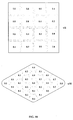
- Proton concentration topographies vii and viii depicted in Figure 1B are two-dimensional proton concentration topographies schematically depicted from above.
- interface volumes are depicted in grey. The proton concentration of each volume is written in units of pH in the center of the volume while the proton concentration of the interface volumes is defined by the neighboring volumes defining the interface volume.
- Proton concentration topography vii comprises sixteen discrete neighboring volumes, arranged in a 4 volume by 4 volume square array where each non-edge volume is surrounded by four neighboring volumes arranged as a cross.
- Proton concentration topography vii comprises 25 discrete neighboring volumes, arranged in a hexagonal array where each non-edge volume is surrounded by six equidistant neighboring volumes.
- FIG. 1C A number of devices for producing a proton concentration gradient are depicted in Figure 1C , which are outside the scope of the present invention.
- Device 10 comprises ten independently controllable cells 12 arranged in a line to constitute a linear area, each cell 12 configured to produce a specified proton concentration in an associated volume of an environment including an electrolyte held in container 14.
- the volumes associated with each cell 12 are the volume of environment held in container 14 proximal to that cell 12.
- device 10 is configured to allow substantially uninhibited movement of ions between neighboring volumes.
- Device 10 comprises a controller 16 that is functionally associated with each of cells 12 and is used to control the proton concentration produced in the associated volume of each cell 12 by controlling the magnitude of an electric current passing through each cell 12.
- Controller 16 includes a controller input component allowing a user to input a desired proton concentration produced in an associated volume by each cell in order to specify a desired proton concentration topography.
- Device 10 may be used to produce many different proton concentration topographies, including proton topographies i, ii, iii, iv and v depicted in Figure 1A .
- Device 18 depicted in Figure 1C is similar to device 10. However, container 14 is divided into ten subcontainers 14' by impermeable barriers 20.
- container 14 is filled with a fluid environment including an electrolyte so that the level of fluid is lower than the height of barriers 20, the environment held in container 14 is divided into a plurality of physically discrete neighboring volumes where ion movement between neighboring volumes is inhibited.
- each volume associated with a cell 12 is physically defined by a subcontainer 14'.
- device 18 may be used to produce many different proton concentration topographies, including proton concentration topography vi depicted in Figure 1A .
- Container 14 is filled with a fluid environment including an electrolyte so that the level of fluid is higher than the height of barriers 20.
- each volume associated with a cell 12 is only partially physically defined by a subcontainer 14'.
- device 18 may be used to produce many different proton concentration topographies, including proton topographies i, ii, iii, iv and v depicted in Figure 1A .
- Device 22 depicted in Figure 1C comprises sixteen independently controllable cells 12 arranged in a four cell by four cell square array, each cell 12 configured to produce a specified proton concentration in an associated volume of an environment including an electrolyte held in container 14.
- the volumes associated with each cell 12 are the volume of environment held in container 14 proximal to that cell 12.
- device 10 is configured to allow substantially uninhibited movement of ions between neighboring volumes.
- Device 22 may be used to produce many different proton concentration topographies, including proton concentration topography vii depicted in Figure 1B .
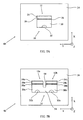
- FIG. 2A a device for producing a specified proton concentration in an environment, cell 12 is schematically depicted in side cross-section.
- Cell 12 comprises a counter electrode 24, a working electrode 26 (a mesh permeable to the passage of ions), an electrolysis volume 28 (the volume between working electrode 26 and counter electrode 24), a second volume 30 on the opposite side of working electrode 26 and a proton concentration sensor 32 in second volume 30, all contained within the volume defined by container 14.
- Electrodes 24 and 26 are functionally associated with controller 16, which is configured to control the magnitude of a current passing between electrodes 24 and 26 when an environment including an electrolyte is contained within container 14 and in contact with electrodes 24 and 26.
- an environment including an electrolyte is added to container 14 filling electrolysis volume 28 and second volume 30 and establishing an electrical circuit including electrodes 24 and 26.
- Controller 16 passes an electrical current through the established circuit between electrodes 24 and 26.
- Electrolysis occurs in electrolysis volume 28, electrolyzing water to generatw electrolysis products such as protons and hydroxyl anions. The protons migrate to the cathode while the hydroxyl anions migrate to the anode, changing the proton concentration in the vicinity of the electrodes.
- Ions in the vicinity of working electrode 26 pass through working electrode into second volume 30, changing the proton concentration in second volume 30 to be substantially equal to that near working electrode 26.
- Proton concentration sensor 32 determines the value of a proton concentration in second volume 30 and reports the value of the proton concentration to controller 16 which then, if necessary, changes the magnitude of the electrical current in response to the reported value in order to produce a desired proton concentration in second volume 30 , as input to controller 16 by a user through the controller input component of controller 16 .
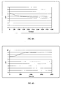
- FIG 2B is shown a graph qualitatively depicting the concentration of protons and hydroxyl anions in device 22 of Figure 2A when activated so that working electrode 26 is an anode and counter electrode 24 is a cathode. It is seen that the proton concentration monotonously decreases through electrolysis volume 28 from a maximum near counter electrode 24 . In the proximity of working electrode 26 as well as in second volume 30 there is a high concentration of hydroxyl anions and consequently a low concentration of protons. It is seen that the concentration of hydroxyl anions in all of second volume 30 is the same and substantially the same as the concentration near working electrode 26 .
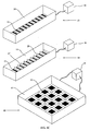
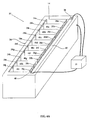
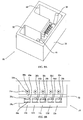
- FIG. 3A An embodiment of a device configured producing a proton concentration topography and useful for isoelectric focusing in accordance with the teachings of the invention, device 36 , is depicted in Figures 3A (perspective), 3B (side view) and 3C (top view).
- Casing 34 substantially a non-conductive rectangular box of transparent polycarbonate with an open top, about 5 cm long, 0.5 cm wide, 0.5 cm deep contains other components of device 36 .
- the volume defined by casing 34 is considered to be a container 14 .
- a substantially standard electrophoresis assembly comprising an isoelectric focusing anode 38 , an isoelectric focusing cathode 40 and an electrophoresis gel 42 (e.g., neutral uncharged polyacrylamide hydrogel available from Bio-Rad Haifa, Ltd., Haifa, Israel).
- electrophoresis gel 42 e.g., neutral uncharged polyacrylamide hydrogel available from Bio-Rad Haifa, Ltd., Haifa, Israel.
- a membrane 44 e.g., a hydrophilic polyvinylidene fluoride (PVDF) membrane with 5 micrometer pores available, for example, as Durapore (SVLP04700) from Millipore, Inc. Billerica, MA, USA
- PVDF hydrophilic polyvinylidene fluoride
- Container 14 contains components of an array of a plurality (ten) independently controllable cells, similar to cell 12 depicted in Figure 2A .
- Each cell of the array of cells is configured to produce a specified proton concentration in an associated volume of gel 42 .
- cells of the array of cells are configured for producing a one-dimensional (linear) proton concentration topography in gel 42 in accordance with aspects of the invention.
- the array of cells includes a single counter electrode 24 (platinum sheet) opposing ten individually controllable working electrodes 26a-26j (platinum mesh, made of 0.1 mm thick wires with 0.1 mm gaps), each working electrode 26 separated from neighboring working electrodes 26 by an electrode separator 46a - 46i (0.1 mm glass walls).
- Working electrodes 26a-26j are placed about 0.5 mm from membrane 44 and about 2 mm from counter electrode 24 by.
- the volume defined between working electrodes 26 and counter electrode 24 is an electrolysis volume 28.
- the volume defined by a working electrode 26 , one or two bordering electrode separators 46 and membrane 44 is a proton reservoir volume 48a - 48j, on the bottom of which is embedded a proton concentration sensor 32a-32j (e.g., Orion 9863BN, Thermo Fisher Scientific Inc., Waltham, MA, USA) and a magnetic stirrer 50a - 50j.
- a proton concentration sensor 32a-32j e.g., Orion 9863BN, Thermo Fisher Scientific Inc., Waltham, MA, USA
- a magnetic stirrer 50a - 50j e.g., Orion 9863BN, Thermo Fisher Scientific Inc., Waltham, MA, USA
- electrolysis volume 28 and proton reservoir volumes 48a-48j are filled with an electrolyte solution (e.g., 0.1 M Na 2 SO 4 in water).
- an electrolyte solution e.g., 0.1 M Na 2 SO 4 in water.
- Isoelectric focusing anode 38 , isoelectric focusing cathode 40 , counter electrode 24 , working electrodes 26 , proton concentration sensors 32 and stirrers 50 are all functionally associated with a controller 16 (e.g., an appropriately configured microprocessor or digital computer with necessary peripheral accessories).
- a controller 16 e.g., an appropriately configured microprocessor or digital computer with necessary peripheral accessories.
- Controller 16 activates each cell so that a selected current, typically between 0 and about 1mA cm -2 (depending on the desired proton concentration) is independently established between counter electrode 24 and each working electrode 26a-26j so that a voltage of between 0 and about 5V exists between counter electrode 24 and each working electrode 26a-26j.
- a selected current typically between 0 and about 1mA cm -2 (depending on the desired proton concentration) is independently established between counter electrode 24 and each working electrode 26a-26j so that a voltage of between 0 and about 5V exists between counter electrode 24 and each working electrode 26a-26j.
- a proton concentration gradient (substantially as depicted in Figure 2B ) is generated in the environment including an electrolyte held in electrolysis volume 28 between counter electrode 24 and each working electrodes 26a - 26j .
- a proton concentration gradient is generated in the environment including an electrolyte held in electrolysis volume 28 between counter electrode 24 and each working electrodes 26a - 26j .
- the proton concentration in each proton reservoir volume 48 influences the proton concentration in gel 42 through membrane 44 so that the proton concentration in a given proton reservoir volume 48 is the same in a volume of gel 42 immediately adjacent to that proton reservoir volume 48.
- the current passing between counter electrode 24 and each working electrode 26a-26j is changed until a desired proton concentration (as specified by controller 16) is produced and detected in an associated proton reservoir volume 48.
- a desired proton concentration (as specified by controller 16)
- the proton concentration in each proton reservoir volume 48 and consequently in the adjacent volume of gel 42 is separately controllable. In such a way, a desired specified proton concentration topography is produced in gel 42 , where each cell produces a specified proton concentration in a volume of gel 42 associated with that cell.
- a mixture of one or more analytes for separation by isolectric focusing is loaded onto gel 42 and a potential (e.g., 700 V) is supplied between isoelectric focusing anode 38 and isoelectric focusing cathode 40 .
- the proton concentration topography inside gel 42 causes separation of the individual analytes in the mixture according to the isoelectric points. The locations of the individual analytes are observed and analyzed in the usual way.
- the potential on working electrodes 26 is optionally changed to generate a different proton concentration topography in order to have a different isoelectric separation which is also observed and analyzed in the usual way.
- a first proton concentration topography is specified to have a proton concentration having pH 5.0 in the volume of gel 42 associated with working electrode 26a , the proton concentration decreasing monotonously and linearly to a proton concentration having a pH 8.0 in the volume of gel 42 associated with working electrode 26j
- a second proton concentration topography is specified to have a proton concentration having pH 5.2 in the volume of gel 42 associated with working electrode 26a , the proton concentration decreasing monotonously and linearly to a proton concentration having a pH 5.9 in the volume of gel 42 associated with working electrode 26j .
- a first proton concentration topography is specified to have a proton concentration having pH 5.0 in the volume of gel 42 associated with working electrode 26a , the proton concentration decreasing monotonously and linearly to a proton concentration having a pH 6.0 in the volume of gel 42 associated with working electrode 26j
- a second proton concentration topography is specified to have a proton concentration having pH 5.8 in the volume of gel 42 associated with working electrode 26a , the proton concentration decreasing monotonously and linearly to a proton concentration having a pH 7.0 in the volume of gel 42 associated with working electrode 26j.
- the proton concentration monotonously decreases.
- the change in proton concentration in a direction through gel 42 may be substantially any desired function, monotonous or not.
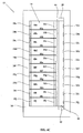
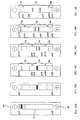
- FIG. 4A perspective view
- 4B side view
- 4C top view
- Device 52 substantially resembles device 36 but includes a number of notable differences.
- One difference is that there is not one counter electrode 24 that functions opposite a plurality of working electrodes 26a-26j but rather a plurality of independent counter electrodes 24a-24j, each functionally associated with a respective working electrode 26a-26j.
- electrode separators 46a-46i separate neighboring counter electrodes 24a-24j as well as neighboring working electrodes 26a-26j, thereby defining a plurality of physically discrete electrolysis volumes 28a-28j.
- proton concentration sensors 32 are embedded inside a gel 42 on a wall of a casing 34 opposite a respective counter electrode 24 so as to measure the actual proton concentration of a volume associated with a working electrode 26 inside gel 42 .
- device 52 is substantially devoid of proton reservoir volumes 48 . Rather, the distance between working electrodes 26 and a membrane 44 is very small, approximately only 0.1 mm.
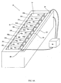
- FIG. 5A perspective view
- 5B side view
- 5C top view
- Device 54 substantially resembles devices 36 and 52 but includes a number of notable differences, including that device 54 is configured so that proton concentration sensors 32 are isolated from the influence of the electric field generated by isoelectric focusing anode 38 and cathode 40 .
- Each proton reservoir volume 48 is divided into two parts, as seen in Figure 5B , a first part 48' (in Figure 5B , 48a' is depicted) and a second part 48 " (in Figure 5B , 48a" is depicted).
- a first part of a proton reservoir volume 48 is defined by a working electrode 26 , one or two bordering electrode separators 46 and membrane 44 so that protons and water molecules can pass substantially uninhibited between first part 48' and gel 42 .
- a second part of a proton reservoir volume 48 is defined by a working electrode 26 and one or two bordering electrode separators 46 .
- Second part 48" is separated from first part 48' and from gel 42 by an insulating partition 56 , for example of polycarbonate, so that movement of protons between second part 48" and gel 42 is inhibited.
- Proton concentration sensors 32 (in Figure 5B , 32a is depicted) are contained within second part 48" of a volume 48 . In such a way, proton concentration sensors 32 are isolated from the electric field between isoelectric focusing anode 38 and cathode 40.
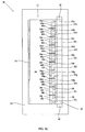
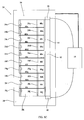
- FIG. 6A An additional embodiment of a device configured for producing a proton concentration topography and useful for isoelectric focusing in accordance with the teachings of the invention, device 58 , is depicted in Figures 6A (perspective view) and 6B (side view).
- Device 58 substantially resembles devices 36, 52 and 54 but includes a number of notable differences. Like in device 36 , device 58 includes proton reservoir volume 48a - 48j , defined by a working electrode 26 , one or two bordering electrode separators 46 and a proton-permeable membrane 44a intimately associated with gel 42 . Like in device 54 , proton concentration sensors 32 are positioned on a wall of a casing 34 opposite a counter electrode 24 , separated from direct contact with a gel 42 by a proton-permeable membrane 44b. However, unlike in device 54 , in device 58 proton concentration sensors 32 are not embedded in gel 42 but rather contact a surface thereof.
- FIG. 9A perspective view
- 9B top detailed view
- Device 66 substantially resembles devices 36, 52 , 54 and 58 but includes a number of notable differences.
- Device 66 includes an array of five independently controllable cells 12a-12e substantially similar to cell 12 depicted in Figure 2A .
- Each cell of the array of cells is configured to produce a specified proton concentration in an associated volume of an environment including an electrolyte held in proton concentration topography channel 72 .
- cells 12 of the array of cells are configured for producing a one-dimensional (linear) proton concentration topography in channel 72 .
- Device 66 is provided with a large anode bath 68 in which isoelectric focusing anode 38 is immersed and a large cathode bath 70 in which isoelectric focusing cathode 40 is immersed.
- components of each cell 12 are isolated from proton concentration topography channel 72 in separate volumes of container 14 to protect the components from damage from the electric field generated between anode 38 and cathode 40 .
- Counter electrode 24 and working electrode 26 are isolated in a volume (which also includes an electrolysis volume 28 and a proton reservoir volume 48) , the volume in fluid communication with proton concentration topography channel 72 through a narrow conduit that constitutes a portion of a respective proton reservoir volume 48 .
- the volume of an environment including an electrolyte that is found in proton concentration topography channel 72 in proximity to the opening of each conduit together with proton reservoir volume 48 comprises the volume associated with each cell 12 in which a specified proton concentration is produced.
- interface volumes having a proton concentration (and in some cases, a proton concentration gradient) related to the proton concentrations of the two neighboring volumes defining the interface volume.
- Each proton concentration sensor 32 is isolated in a respective proton concentration sensor volume 74 from proton concentration topography channel 72 in fluid communication with proton concentration topography channel 72 through a narrow conduit.
- pumps e.g., peristaltic pumps
- suitable device provide fluid communication between a proton concentration sensor volume 74 and a respective proton reservoir volume 48 to ensure that the proper proton concentration is measured.
- the environment including an electrolyte in which a specified proton concentration topography is produced comprises the electrolyte solution and gel 42.
- the environment including an electrolyte in which a specified proton concentration topography is produced comprises the electrolyte solution held in proton concentration topography channel 72.
- the container configured to contain the environment including the electrolyte comprises container 14 , including the portion in which a gel 42 is held or the proton concentration topography channel 72 of device 66.
- the individual independently controllable cells configured to produce a specified proton concentration in an associated volume of an environment including an electrolyte comprise counter electrode 24 , electrolysis volume 28 , a working electrode 26 , a proton concentration sensor 32 and for devices 36, 54, 58 and 66 , a proton reservoir volume 48.
- each cell includes an electrolysis volume 28 between a working electrode 26 and a respective counter electrode 24 .
- the volume of environment associated with a cell in which a specified proton concentration is produced includes a proton reservoir volume 48 as well as the volumes of membrane(s) 44 and gel 42 located proximally to a respective proton reservoir volume 48 .
- the volume of environment associated with a cell in which a specified proton concentration is produced includes a the volumes of membrane 44 and gel 42 located proximally to a respective working electrode 26 .
- proton concentration sensors 32 measure proton concentrations produced by a cell (e.g., 12) and report the measured concentration to controller 16. This allows monitoring of the actually produced proton concentrations and, if necessary, adjustment of the current passing between a working electrode 26 and a counter electrode 24 to maintain the actually produced proton concentration as a specified proton concentration.
- gel 42 or environment held in channel 72 is divided into a plurality of discrete volumes characterized by a specified proton concentration, each volume associated with and in proximity to a specific working electrode 26 and in the case of devices 36, 54, 58 and 66 a respective proton reservoir volume 48 .
- interface volumes having a proton concentration (and in some cases, a proton concentration gradient) related to the proton concentrations of the two neighboring volumes defining the interface volume.
- a device of the invention such as device 36, 52, 54, 58 or 66 is configured so that a produced proton concentration topography in a gel 42 or proton concentration topography channel 72 is mutable and a proton concentration topography may be changed as desired and/or varied with time.
- a controller 16 is provided with a user interface that allows a user to provide instructions specifying a desired proton concentration produced by each cell or to specify a desired proton concentration topography, as needed. Upon receipt of user instructions, controller 16 changes (or maintains) the current passing between one or more counter electrodes 24 and respective working electrodes 26 so as to produce the desired proton concentration topography.
- controller 16 is provided with a timer and instructions as how to change a produced proton concentration topography as a function of time. With reference to the timer, controller 16 changes (or maintains) the current passing between one or more counter electrodes 24 and respective working electrodes 26 in accordance with the instructions so as to change the produced proton concentration topography as a function of time.
- the change in current may be such that the change in proton concentration produced by a cell changes in a step-wise fashion (that is to say, is allowed to stabilize at a certain value and is maintained at that value for some time) or continuously.
- each proton reservoir volume 48 is provided with a dedicated stirrer 50 .
- a proton reservoir volume is devoid of an actual stirrer and a uniform proton concentration is achieved by diffusion of protons inside the proton reservoir volume.
- a device such as a device 36, 52, 54, 58 or 66 may lead to the generation of heat, especially when a current passes between isoelectric focusing anode 38 and isoelectric focusing cathode 40 .
- a device is provided with a cooling system, for instance comprising components to cool the environment including an electrolyte.
- a device such as device 66 depicted in Figures 9 is provided with cooling elements in the walls of anode bath 68 and cathode bath 70 .
- isoelectric focusing is performed in a portion of the environment that is gel 42 or in channel 72 in which a proton concentration topography is produced that is non-immobilized and is mutable.
- FIG. 10A-10F schematically depicts the location of the five proteins of the mixture (each depicted as a horizontal strip) in gel 42 , a standard electrophoresis / isoelectric focusing gel, in which a proton concentration topography is produced and across which an electrical field is applied between isoelectric focusing anode 38 and isoelectric focusing cathode 40 .
- a characteristic of the embodiment is that electrophoretic separation and isoelectric resolution are performed on parallel axes, and not perpendicular axes as known in the art.
- a uniform proton concentration (pH 7) is produced throughout gel 42 and the mixture of proteins is loaded onto gel 42 in the usual way.
- a potential is applied between anode 38 and cathode 40 .
- a complex proton concentration topography is produced to further resolve the proteins of interest.
- the proton concentration monotonously decreases from pH 2 (on the side of anode 38) to pH 10 (on the side of cathode 40).
- a cathode region 78 (a volume of gel 42 which includes two "unwanted” proteins) the proton concentration decreases monotonously from pH 2 to pH 10 proximal to cathode 40 .
- anode region 80 (a volume of gel 42 which includes an "unwanted” protein) the proton concentration increases monotonously from pH 10 to pH 2 proximal to anode 38 .
- central region 76 is lengthened, increasing the spatial resolution of the two proteins of interest.
- Cathode region 78 and Anode region 80 are made smaller, forcing the three "unwanted" proteins closer together,
- the present invention provides a method of analyzing an analyte using isolectric focusing, as described above, where the second non-immobilized proton concentration topography is chosen so that components of interest are spatially resolved to a greater extent than in the preceding non-immobilized proton concentration topography.
- isoelectric focusing is performed in an environment that is a fluid such as a liquid, e.g., an electrolyte solution, for example in channel 72 of device 66 or in some such environments gel 42 is removed and replaced with electrolyte solution.
- a fluid such as a liquid
- electrolyte solution for example in channel 72 of device 66 or in some such environments gel 42 is removed and replaced with electrolyte solution.
- the movement of ions between two neighboring volumes of the environment in gel 42 is substantially uninhibited, a configuration that is suitable for many uses, for example isoelectric focusing.
- the movement of ions between two neighboring volumes is inhibited.
- one such embodiment where ion movement between neighboring volumes is substantially inhibited is similar to device 36 depicted in Figures 3 where gel 42 is replaced with an insulating glass plate.
- the volume of the environment associated with an individual cell in which a specified proton concentration is produced includes only a respective proton reservoir volume 48. Such embodiments are useful, for example for the display of data.
- proton reservoir volumes 48 and electrolysis volume 28 are filled with an environment including an electrolyte and a pH sensitive indicator having an appearance that is dependent on the proton concentration in the environment, e.g. Yamada Universal pH indicator (see for example, Foster SF and Gruntfest in J.Chem.Educ. 1937 , 14, 274).
- the individual cells are activated to produce specified proton concentrations in the respective proton reservoir volume 48 .
- the indicator in proton reservoir volumes 48 adopts a color that is dependent on the produced proton concentration.
- the proton concentration in each proton reservoir volumes 48 is specified so that when the collective appearance of proton reservoir volumes 48 (that is of the produced proton concentration topography as made apparent by the pH indicator in the environment) constitutes a display of data for example an image.
- the display of data using a device similar to device 36 as described herein above having a one-dimensional array of cells producing a one-dimensional proton concentration topography is limited.
- Analogous devices having a two-dimensional array of cells to produce a two-dimensional proton concentration topography have greater utility, especially for the display of actual images.
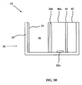
- a device for the production of a proton concentration in a liquid environment including an electrolyte, device 60 was made and used in accordance with the teachings of the invention to produce a specified proton concentration.
- Device 60 is schematically depicted in Figure 7A in top view.
- Casing 34 of device 60 is a block of polymethyl(methacrylate) (Perspex®) 4 cm long (y dimension), 3 cm wide (x dimension) and 2 cm high (z dimension) in which a container 14 was hollowed to accommodate a cell 12 for producing a specified proton concentration in an environment including an electrolyte, cell 12 being 1 cm long (y dimension), 0.6 cm wide (x dimension) and 1 cm deep (z dimension).
- Counter electrode 24 of 0.1 mm thick platinum mesh was placed along a wall of cell 12 .
- Working electrode 26 was placed inside container 14, in parallel to and spaced 2mm from counter electrode 24 .
- Proton concentration sensor 32 (Orion 9863BN, Thermo Fisher Scientific Inc., Waltham, MA, USA) was placed on the wall of cell 12 opposite counter electrode 24 , inside volume 30.
- Container 14 was filled with an electrolyte solution of 0.1 M Na 2 SO 4 in water.
- Proton concentration sensor 32 was connected to a suitable display device to indicate what proton concentration was measured by that sensor in volume 30 .
- Device 60 was used produce a specified proton concentration in an environment held in volume 30 .
- Counter electrode 24 and working electrode 26 were functionally associated with a variable power supply to establish an electrical circuit.
- the variable power supply was used to pass a current of between about 0 and about 1mA cm -2 at a potential of between about 0 and about 5V through the electrical circuit including the electrodes.
- the current passing through the circuit led to hydrolysis of water and the generation of protons and hydroxyl anions in the volume of electrolysis chamber 28 .
- the concentration of protons increased in proximity of the cathode while the concentration of protons decreased in proximity of the anode.
- working electrode 26 was made of mesh and therefore permeable to ions, generated ions from the vicinity of a working electrode 26 passed through working electrode 26 into the electrolyte solution held in volume 30 .
- a device for the production of a proton concentration topography in a liquid environment device 62 was made and used in accordance with the teachings of the invention to produce a specified proton concentration topography.
- Device 62 is schematically depicted in Figure 7B in top view.
- Casing 34 of device 60 is a block of polymethyl(methacrylate) (Perspex®) 4 cm long (y dimension), 3 cm wide (x dimension) and 2 cm high (z dimension) in which a container 14 was hollowed to accommodate two cells 12a and 12b , each for producing a specified proton concentration in an environment including an electrolyte, each cell 12a or 12b being 1 cm long (y dimension), 0.6 cm wide (x dimension) and 1 cm deep (z dimension). Separating the hollows of container 14 corresponding to each cell 12a and 12b is a 0.2 cm wide (x dimension) impermeable wall 64 . Counter electrodes 24a and 24b of 0.1 mm thick platinum mesh were placed along a wall of cell 12a and 12b respectively.
- Working electrodes 26a and 26b were placed inside container 14 , in parallel to and spaced 2mm from counter electrodes 24a and 24b .
- proton concentration sensors 32a and 32b (Orion 9863BN, Thermo Fisher Scientific Inc., Waltham, MA, USA) were placed on the walls of cells 12a and 12b opposite counter electrodes 24a and 24b , inside volumes 30a and 30b .
- Container 14 was filled with an electrolyte solution of 0.1 M Na 2 SO 4 in water.
- Each proton concentration sensor 32a and 32b was connected to a suitable display device to indicate what pH was measured by that sensor in a corresponding volume 30a or 30b .
- Device 62 was used to produce a specified proton concentration topography in the electrolyte solution in a portion of container 14 including volume 30a, 30b and the interface volume 74 there between.
- each circuit including an electrode pair 24a/26a or 24b/26b and a separate independent variable power supply.
- Each variable power supply was used to independently pass a current of between about 0 and about 1mA cm -2 at a potential of between about 0 and about 5V through a respective electrical circuit.
- the current passing through the circuit led to hydrolysis of water and the generation of protons and hydroxyl anions in the volume of electrolyte chamber 28a or 28b .
- the concentration of protons increased in proximity of the cathode while the concentration of protons decreased in proximity of the anode.
- working electrodes 26a and 26b were of mesh and therefore permeable to ions, generated ions passed from the vicinity of a working electrode 26 through the working electrodes 26 into the electrolyte solution held in a respective associated volume 30a or 30b.
- the current applied between counter electrode 24a and working electrode 26a was adjusted with reference to the readings of proton concentration sensor 32a until a proton concentration corresponding to a pH of 5.2 was measured in the electrolyte solution held in volume 30a associated with working electrode 26a while the current applied between counter electrode 24b and working electrode 26b was adjusted with reference to the readings of proton concentration sensor 32b until a proton concentration corresponding to a pH of 9 was measured in the electrolytic solution held in volume 30b associated with working electrode 26b , see Figure 8C .
Landscapes
- Life Sciences & Earth Sciences (AREA)
- Health & Medical Sciences (AREA)
- Chemical & Material Sciences (AREA)
- Molecular Biology (AREA)
- Chemical Kinetics & Catalysis (AREA)
- Electrochemistry (AREA)
- Pathology (AREA)
- Analytical Chemistry (AREA)
- Biochemistry (AREA)
- General Health & Medical Sciences (AREA)
- General Physics & Mathematics (AREA)
- Immunology (AREA)
- Physics & Mathematics (AREA)
- Environmental & Geological Engineering (AREA)
- Engineering & Computer Science (AREA)
- Hydrology & Water Resources (AREA)
- Water Supply & Treatment (AREA)
- Organic Chemistry (AREA)
- General Chemical & Material Sciences (AREA)
- Investigating Or Analyzing Materials By The Use Of Electric Means (AREA)
- Electrolytic Production Of Non-Metals, Compounds, Apparatuses Therefor (AREA)
- Investigating Or Analysing Biological Materials (AREA)
- Peptides Or Proteins (AREA)
- Micro-Organisms Or Cultivation Processes Thereof (AREA)
- Immobilizing And Processing Of Enzymes And Microorganisms (AREA)
Priority Applications (1)
| Application Number | Priority Date | Filing Date | Title |
|---|---|---|---|
| EP12177368.3A EP2559666B1 (en) | 2007-08-27 | 2008-08-26 | pH gradients controlled by electrolysis, and their use in isoelectric focusing |
Applications Claiming Priority (3)
| Application Number | Priority Date | Filing Date | Title |
|---|---|---|---|
| US93569807P | 2007-08-27 | 2007-08-27 | |
| US3925708P | 2008-03-25 | 2008-03-25 | |
| PCT/IL2008/001159 WO2009027970A2 (en) | 2007-08-27 | 2008-08-26 | Ph gradients controlled by electrolysis, and their use in isoelectric focusing |
Related Child Applications (2)
| Application Number | Title | Priority Date | Filing Date |
|---|---|---|---|
| EP12177368.3A Division-Into EP2559666B1 (en) | 2007-08-27 | 2008-08-26 | pH gradients controlled by electrolysis, and their use in isoelectric focusing |
| EP12177368.3A Division EP2559666B1 (en) | 2007-08-27 | 2008-08-26 | pH gradients controlled by electrolysis, and their use in isoelectric focusing |
Publications (2)
| Publication Number | Publication Date |
|---|---|
| EP2193100A2 EP2193100A2 (en) | 2010-06-09 |
| EP2193100B1 true EP2193100B1 (en) | 2014-05-07 |
Family
ID=40254551
Family Applications (2)
| Application Number | Title | Priority Date | Filing Date |
|---|---|---|---|
| EP08789831.8A Not-in-force EP2193100B1 (en) | 2007-08-27 | 2008-08-26 | pH gradients controlled by electrolysis, and their use in isoelectric focusing |
| EP12177368.3A Not-in-force EP2559666B1 (en) | 2007-08-27 | 2008-08-26 | pH gradients controlled by electrolysis, and their use in isoelectric focusing |
Family Applications After (1)
| Application Number | Title | Priority Date | Filing Date |
|---|---|---|---|
| EP12177368.3A Not-in-force EP2559666B1 (en) | 2007-08-27 | 2008-08-26 | pH gradients controlled by electrolysis, and their use in isoelectric focusing |
Country Status (8)
| Country | Link |
|---|---|
| US (2) | US9274082B2 (enExample) |
| EP (2) | EP2193100B1 (enExample) |
| JP (1) | JP5702142B2 (enExample) |
| KR (1) | KR20100053672A (enExample) |
| CN (2) | CN101868425B (enExample) |
| AU (1) | AU2008293381B2 (enExample) |
| CA (1) | CA2697649C (enExample) |
| WO (1) | WO2009027970A2 (enExample) |
Families Citing this family (17)
| Publication number | Priority date | Publication date | Assignee | Title |
|---|---|---|---|---|
| EP2193100B1 (en) | 2007-08-27 | 2014-05-07 | Technion Research and Development Foundation, Limited | pH gradients controlled by electrolysis, and their use in isoelectric focusing |
| US10107782B2 (en) * | 2008-01-25 | 2018-10-23 | ProteinSimple | Method to perform limited two dimensional separation of proteins and other biologicals |
| CA2770270C (en) * | 2009-08-18 | 2018-08-14 | Technion Research & Development Foundation Ltd. | Proton concentration topographies, methods and devices for producing the same |
| US8864970B2 (en) | 2009-08-18 | 2014-10-21 | Technion Research & Development Foundation Limited | Methods and devices of separating molecular analytes |
| JP5950429B2 (ja) * | 2011-05-13 | 2016-07-13 | シャープ株式会社 | 電気泳動方法、及び電気泳動装置 |
| CN104024856B (zh) * | 2011-11-04 | 2018-10-26 | 生物辐射实验室股份有限公司 | 基于pI的蛋白质分级 |
| US9766207B2 (en) | 2011-11-04 | 2017-09-19 | Bio-Rad Laboratories, Inc. | Affinity methods and compositions employing electronic control of pH |
| WO2013067509A1 (en) | 2011-11-04 | 2013-05-10 | Bio-Rad Laboratories, Inc. | Simultaneous purification of cell components |
| CN104024396A (zh) | 2011-11-04 | 2014-09-03 | 生物辐射实验室股份有限公司 | 采用pH的电子控制的亲和方法及组合物 |
| CN102565171A (zh) * | 2012-01-05 | 2012-07-11 | 厦门大学 | 一种用于等电聚焦分离的微流控芯片 |
| US9658195B2 (en) | 2012-02-15 | 2017-05-23 | Bio-Rad Laboratories, Inc. | Electronic control of pH and ionic strength |
| US9321012B2 (en) | 2012-04-04 | 2016-04-26 | Bio-Rad Laboratories, Inc. | Electronic protein fractionation |
| CN104034789A (zh) * | 2013-04-02 | 2014-09-10 | 上海交通大学 | 蛋白质等电聚焦电泳的装置 |
| CN106267304B (zh) * | 2015-06-09 | 2019-10-18 | 海南光宇生物科技有限公司 | 具有酸碱性的生物纤维素凝胶膜及由其制备的医用敷料 |
| CN106260992B (zh) * | 2015-06-09 | 2020-02-18 | 海南椰国食品有限公司 | 一种含有酸性椰果和/或碱性椰果的食品 |
| EP3653121A1 (en) * | 2018-11-14 | 2020-05-20 | Koninklijke Philips N.V. | Sensor unit, body fluid monitoring device and method for detecting an analyte |
| CN119470588A (zh) * | 2024-11-18 | 2025-02-18 | 中国科学院空天信息创新研究院 | 集成式多种重金属检测微传感器 |
Family Cites Families (37)
| Publication number | Priority date | Publication date | Assignee | Title |
|---|---|---|---|---|
| JP2591738B2 (ja) | 1985-08-21 | 1997-03-19 | ベーリンガー マンヘイム コーポレイション | 特異的結合アッセイにおける成分の分離,混合および検出のための方法および装置 |
| US4670119A (en) * | 1985-10-25 | 1987-06-02 | Hurd Stanley M | Isoelectric focusing device and process |
| US4900414A (en) * | 1988-08-19 | 1990-02-13 | Drug Delivery Systems Inc. | Commercial separation system and method using electrokinetic techniques |
| US5160594A (en) | 1989-03-08 | 1992-11-03 | Board Of Regents Of The University Of Texas System | Apparatus and methods for isoelectric focusing of amphoteric substances incorporating ion selective membranes in electrode chambers |
| DE3929137C1 (enExample) | 1989-09-01 | 1991-02-28 | Fraunhofer-Gesellschaft Zur Foerderung Der Angewandten Forschung Ev, 8000 Muenchen, De | |
| US5110434A (en) | 1990-12-20 | 1992-05-05 | Bio-Rad Laboratories, Inc. | Use of zwitterions to mobilize isoelectrically focused ampholyte zones |
| US5646001A (en) | 1991-03-25 | 1997-07-08 | Immunivest Corporation | Affinity-binding separation and release of one or more selected subset of biological entities from a mixed population thereof |
| GB2275974B (en) | 1993-03-10 | 1996-01-10 | Curty Payen Sa | Improvements in and relating to gaskets |
| US6129828A (en) * | 1996-09-06 | 2000-10-10 | Nanogen, Inc. | Apparatus and methods for active biological sample preparation |
| JPH0933479A (ja) * | 1995-07-18 | 1997-02-07 | Mizu Kk | センサカバー及びこれを用いた電解水生成装置 |
| US5993627A (en) | 1997-06-24 | 1999-11-30 | Large Scale Biology Corporation | Automated system for two-dimensional electrophoresis |
| US6296752B1 (en) * | 1998-06-05 | 2001-10-02 | Sarnoff Corporation | Apparatus for separating molecules |
| JP3113645B2 (ja) * | 1999-03-01 | 2000-12-04 | ファースト・オーシャン株式会社 | 電解水製造法 |
| AU4773400A (en) | 1999-05-28 | 2000-12-18 | Leisamon (Israel), Ltd. | Methods and apparatus for nonlinear mobility electrophoresis separation |
| DE10047088C2 (de) * | 2000-09-21 | 2002-10-17 | Gerhard Weber | Medium für analytische und präparative Elektrophorese |
| JP2002265494A (ja) | 2001-03-06 | 2002-09-18 | Tokuyama Corp | 混合物から高純度化された目的物を製造する方法 |
| WO2003008977A2 (en) | 2001-07-16 | 2003-01-30 | Protein, Forest, Inc. | Arrays of buffers for analysing biomolecules by their isoelectric point |
| GB0121189D0 (en) * | 2001-08-31 | 2001-10-24 | Diagnoswiss Sa | Apparatus and method for separating an analyte |
| SE0203773D0 (sv) | 2002-12-19 | 2002-12-19 | Capture Device Ab | Method and device for capturing charged molecules traveling in a flow stream |
| US7150813B2 (en) * | 2003-06-12 | 2006-12-19 | Palo Alto Research Center Incorporated | Isoelectric focusing (IEF) of proteins with sequential and oppositely directed traveling waves in gel electrophoresis |
| AU2004269196B2 (en) | 2003-09-03 | 2010-03-04 | Shmuel Bukshpan | Methods and apparatus for rapid crystallization of biomolecules |
| JP2006213932A (ja) * | 2004-05-07 | 2006-08-17 | Honda Motor Co Ltd | 電解水生成用電極 |
| CN1258828C (zh) * | 2004-02-13 | 2006-06-07 | 清华大学 | 一种质子交换膜燃料电池多元催化剂的制备方法 |
| US7238272B2 (en) * | 2004-02-27 | 2007-07-03 | Yoichi Sano | Production of electrolytic water |
| EP1776581B1 (en) | 2004-07-19 | 2015-05-06 | ProteinSimple | Method for protein detection |
| US7749370B2 (en) | 2005-02-03 | 2010-07-06 | Osao Sumita | Manufacturing method of oxidative water to be employed for sterilization |
| JP5129442B2 (ja) * | 2005-02-08 | 2013-01-30 | エア・ウォーター株式会社 | 液体の帯電物質の濃度調節装置 |
| JP4856530B2 (ja) | 2005-12-21 | 2012-01-18 | ミドリ安全株式会社 | 電解水の有効塩素濃度調節方法、電解水のpH調節方法および電解水生成装置。 |
| EP1986959B1 (de) | 2006-02-17 | 2010-10-27 | Actides Gmbh | Verfahren zur herstellung eines desinfektionsmittels durch elektrochemische aktivierung (eca) von wasser |
| JP3163188U (ja) | 2007-03-13 | 2010-10-07 | シーメンス ウォーター テクノロジース コーポレイション | 酸及び塩基生成のための装置及び方法 |
| US20110100821A1 (en) | 2007-04-20 | 2011-05-05 | Brian Furmanski | Mineral oil free isoelectric focusing apparatus for immobilized ph gradient strips |
| CN101294930B (zh) | 2007-04-27 | 2013-08-14 | 杨春 | 一种整体型固定化pH梯度的制备方法及其应用 |
| US8366899B2 (en) | 2007-06-22 | 2013-02-05 | Massachusetts Institute Of Technology | Isoelectric focusing systems and methods |
| EP2193100B1 (en) | 2007-08-27 | 2014-05-07 | Technion Research and Development Foundation, Limited | pH gradients controlled by electrolysis, and their use in isoelectric focusing |
| CA2770270C (en) | 2009-08-18 | 2018-08-14 | Technion Research & Development Foundation Ltd. | Proton concentration topographies, methods and devices for producing the same |
| US8864970B2 (en) | 2009-08-18 | 2014-10-21 | Technion Research & Development Foundation Limited | Methods and devices of separating molecular analytes |
| CN104024856B (zh) | 2011-11-04 | 2018-10-26 | 生物辐射实验室股份有限公司 | 基于pI的蛋白质分级 |
-
2008
- 2008-08-26 EP EP08789831.8A patent/EP2193100B1/en not_active Not-in-force
- 2008-08-26 EP EP12177368.3A patent/EP2559666B1/en not_active Not-in-force
- 2008-08-26 CN CN2008801146906A patent/CN101868425B/zh not_active Expired - Fee Related
- 2008-08-26 US US12/675,794 patent/US9274082B2/en active Active
- 2008-08-26 JP JP2010522513A patent/JP5702142B2/ja not_active Expired - Fee Related
- 2008-08-26 KR KR1020107006740A patent/KR20100053672A/ko not_active Ceased
- 2008-08-26 CN CN201210450797.6A patent/CN103134843B/zh not_active Expired - Fee Related
- 2008-08-26 WO PCT/IL2008/001159 patent/WO2009027970A2/en not_active Ceased
- 2008-08-26 AU AU2008293381A patent/AU2008293381B2/en not_active Ceased
- 2008-08-26 CA CA2697649A patent/CA2697649C/en active Active
-
2016
- 2016-02-28 US US15/055,601 patent/US10132776B2/en active Active
Non-Patent Citations (1)
| Title |
|---|
| HUANG TIEMIN ET AL: "Capillary isoelectric focusing without carrier ampholytes", ANALYTICAL CHEMISTRY, AMERICAN CHEMICAL SOCIETY, US, vol. 72, no. 19, 1 October 2000 (2000-10-01), pages 4758 - 4761, XP002584974, ISSN: 0003-2700, [retrieved on 20000901], DOI: 10.1021/AC000599L * |
Also Published As
| Publication number | Publication date |
|---|---|
| US20160178578A1 (en) | 2016-06-23 |
| WO2009027970A2 (en) | 2009-03-05 |
| US10132776B2 (en) | 2018-11-20 |
| EP2193100A2 (en) | 2010-06-09 |
| US20100307920A1 (en) | 2010-12-09 |
| CN103134843B (zh) | 2014-11-12 |
| KR20100053672A (ko) | 2010-05-20 |
| EP2559666A2 (en) | 2013-02-20 |
| AU2008293381B2 (en) | 2012-07-19 |
| US9274082B2 (en) | 2016-03-01 |
| JP5702142B2 (ja) | 2015-04-15 |
| AU2008293381A1 (en) | 2009-03-05 |
| CN101868425A (zh) | 2010-10-20 |
| CN103134843A (zh) | 2013-06-05 |
| CN101868425B (zh) | 2013-01-02 |
| EP2559666A3 (en) | 2013-04-03 |
| WO2009027970A3 (en) | 2009-05-14 |
| EP2559666B1 (en) | 2014-07-23 |
| JP2010538255A (ja) | 2010-12-09 |
| CA2697649C (en) | 2016-08-09 |
| CA2697649A1 (en) | 2009-03-05 |
Similar Documents
| Publication | Publication Date | Title |
|---|---|---|
| EP2193100B1 (en) | pH gradients controlled by electrolysis, and their use in isoelectric focusing | |
| US7169609B2 (en) | Multiwell plate assembly for use in high throughput assays | |
| KR20110116008A (ko) | 샘플 중의 하전된 종의 농도를 측정하기 위한 장치 | |
| US4670119A (en) | Isoelectric focusing device and process | |
| EP1877764B1 (en) | Method for electrophoresis involving parallel and simultaneous separation | |
| Chatterjee | Generalized numerical formulations for multi-physics microfluidics-type applications | |
| IL204182A (en) | The degree of acidity controlled by electrolysis and their use in isoelectric targeting | |
| KR101996722B1 (ko) | 다채널 박막전극을 이용한 전기적 생체분자 이동방법 | |
| Hagedorn et al. | Amperometric pH regulation–a flexible tool for rapid and precise temporal control over the pH of an electrolyte solution | |
| JPH03167468A (ja) | 多電極電気泳動装置 | |
| JP2009192479A (ja) | 微粒子測定装置およびそれに用いる電極 | |
| Lingenfelter et al. | Numerical solution of the coupled Nernst-Planck and Poisson equations for ion-selective membrane potentials | |
| Chatterjee et al. | Fully Coupled Computational Modeling of Transport Phenomena in Microfluidics Applications | |
| EP2146200A1 (en) | Device and method for isoelectric focusing | |
| JP2014160095A (ja) | 試料中の荷電種の濃度を測定するための装置 | |
| CN104155356A (zh) | 用于测量样本中的带电粒种浓度的装置 |
Legal Events
| Date | Code | Title | Description |
|---|---|---|---|
| PUAI | Public reference made under article 153(3) epc to a published international application that has entered the european phase |
Free format text: ORIGINAL CODE: 0009012 |
|
| 17P | Request for examination filed |
Effective date: 20100325 |
|
| AK | Designated contracting states |
Kind code of ref document: A2 Designated state(s): AT BE BG CH CY CZ DE DK EE ES FI FR GB GR HR HU IE IS IT LI LT LU LV MC MT NL NO PL PT RO SE SI SK TR |
|
| AX | Request for extension of the european patent |
Extension state: AL BA MK RS |
|
| 17Q | First examination report despatched |
Effective date: 20100720 |
|
| DAX | Request for extension of the european patent (deleted) | ||
| GRAP | Despatch of communication of intention to grant a patent |
Free format text: ORIGINAL CODE: EPIDOSNIGR1 |
|
| INTG | Intention to grant announced |
Effective date: 20131011 |
|
| RAP1 | Party data changed (applicant data changed or rights of an application transferred) |
Owner name: TECHNION RESEARCH AND DEVELOPMENT FOUNDATION, LIMI |
|
| RIN1 | Information on inventor provided before grant (corrected) |
Inventor name: BROD, ELAD Inventor name: SIVAN, URI |
|
| GRAS | Grant fee paid |
Free format text: ORIGINAL CODE: EPIDOSNIGR3 |
|
| GRAA | (expected) grant |
Free format text: ORIGINAL CODE: 0009210 |
|
| AK | Designated contracting states |
Kind code of ref document: B1 Designated state(s): AT BE BG CH CY CZ DE DK EE ES FI FR GB GR HR HU IE IS IT LI LT LU LV MC MT NL NO PL PT RO SE SI SK TR |
|
| REG | Reference to a national code |
Ref country code: GB Ref legal event code: FG4D |
|
| REG | Reference to a national code |
Ref country code: AT Ref legal event code: REF Ref document number: 666511 Country of ref document: AT Kind code of ref document: T Effective date: 20140515 |
|
| REG | Reference to a national code |
Ref country code: IE Ref legal event code: FG4D |
|
| REG | Reference to a national code |
Ref country code: DE Ref legal event code: R096 Ref document number: 602008032123 Country of ref document: DE Effective date: 20140618 |
|
| REG | Reference to a national code |
Ref country code: AT Ref legal event code: MK05 Ref document number: 666511 Country of ref document: AT Kind code of ref document: T Effective date: 20140507 |
|
| REG | Reference to a national code |
Ref country code: NL Ref legal event code: VDEP Effective date: 20140507 |
|
| REG | Reference to a national code |
Ref country code: LT Ref legal event code: MG4D |
|
| PG25 | Lapsed in a contracting state [announced via postgrant information from national office to epo] |
Ref country code: IS Free format text: LAPSE BECAUSE OF FAILURE TO SUBMIT A TRANSLATION OF THE DESCRIPTION OR TO PAY THE FEE WITHIN THE PRESCRIBED TIME-LIMIT Effective date: 20140907 Ref country code: NO Free format text: LAPSE BECAUSE OF FAILURE TO SUBMIT A TRANSLATION OF THE DESCRIPTION OR TO PAY THE FEE WITHIN THE PRESCRIBED TIME-LIMIT Effective date: 20140807 Ref country code: LT Free format text: LAPSE BECAUSE OF FAILURE TO SUBMIT A TRANSLATION OF THE DESCRIPTION OR TO PAY THE FEE WITHIN THE PRESCRIBED TIME-LIMIT Effective date: 20140507 Ref country code: FI Free format text: LAPSE BECAUSE OF FAILURE TO SUBMIT A TRANSLATION OF THE DESCRIPTION OR TO PAY THE FEE WITHIN THE PRESCRIBED TIME-LIMIT Effective date: 20140507 Ref country code: CY Free format text: LAPSE BECAUSE OF FAILURE TO SUBMIT A TRANSLATION OF THE DESCRIPTION OR TO PAY THE FEE WITHIN THE PRESCRIBED TIME-LIMIT Effective date: 20140507 Ref country code: GR Free format text: LAPSE BECAUSE OF FAILURE TO SUBMIT A TRANSLATION OF THE DESCRIPTION OR TO PAY THE FEE WITHIN THE PRESCRIBED TIME-LIMIT Effective date: 20140808 |
|
| PG25 | Lapsed in a contracting state [announced via postgrant information from national office to epo] |
Ref country code: SE Free format text: LAPSE BECAUSE OF FAILURE TO SUBMIT A TRANSLATION OF THE DESCRIPTION OR TO PAY THE FEE WITHIN THE PRESCRIBED TIME-LIMIT Effective date: 20140507 Ref country code: ES Free format text: LAPSE BECAUSE OF FAILURE TO SUBMIT A TRANSLATION OF THE DESCRIPTION OR TO PAY THE FEE WITHIN THE PRESCRIBED TIME-LIMIT Effective date: 20140507 Ref country code: PL Free format text: LAPSE BECAUSE OF FAILURE TO SUBMIT A TRANSLATION OF THE DESCRIPTION OR TO PAY THE FEE WITHIN THE PRESCRIBED TIME-LIMIT Effective date: 20140507 Ref country code: AT Free format text: LAPSE BECAUSE OF FAILURE TO SUBMIT A TRANSLATION OF THE DESCRIPTION OR TO PAY THE FEE WITHIN THE PRESCRIBED TIME-LIMIT Effective date: 20140507 Ref country code: HR Free format text: LAPSE BECAUSE OF FAILURE TO SUBMIT A TRANSLATION OF THE DESCRIPTION OR TO PAY THE FEE WITHIN THE PRESCRIBED TIME-LIMIT Effective date: 20140507 Ref country code: LV Free format text: LAPSE BECAUSE OF FAILURE TO SUBMIT A TRANSLATION OF THE DESCRIPTION OR TO PAY THE FEE WITHIN THE PRESCRIBED TIME-LIMIT Effective date: 20140507 |
|
| PG25 | Lapsed in a contracting state [announced via postgrant information from national office to epo] |
Ref country code: PT Free format text: LAPSE BECAUSE OF FAILURE TO SUBMIT A TRANSLATION OF THE DESCRIPTION OR TO PAY THE FEE WITHIN THE PRESCRIBED TIME-LIMIT Effective date: 20140908 |
|
| PG25 | Lapsed in a contracting state [announced via postgrant information from national office to epo] |
Ref country code: CZ Free format text: LAPSE BECAUSE OF FAILURE TO SUBMIT A TRANSLATION OF THE DESCRIPTION OR TO PAY THE FEE WITHIN THE PRESCRIBED TIME-LIMIT Effective date: 20140507 Ref country code: BE Free format text: LAPSE BECAUSE OF FAILURE TO SUBMIT A TRANSLATION OF THE DESCRIPTION OR TO PAY THE FEE WITHIN THE PRESCRIBED TIME-LIMIT Effective date: 20140507 Ref country code: EE Free format text: LAPSE BECAUSE OF FAILURE TO SUBMIT A TRANSLATION OF THE DESCRIPTION OR TO PAY THE FEE WITHIN THE PRESCRIBED TIME-LIMIT Effective date: 20140507 Ref country code: RO Free format text: LAPSE BECAUSE OF FAILURE TO SUBMIT A TRANSLATION OF THE DESCRIPTION OR TO PAY THE FEE WITHIN THE PRESCRIBED TIME-LIMIT Effective date: 20140507 Ref country code: SK Free format text: LAPSE BECAUSE OF FAILURE TO SUBMIT A TRANSLATION OF THE DESCRIPTION OR TO PAY THE FEE WITHIN THE PRESCRIBED TIME-LIMIT Effective date: 20140507 Ref country code: DK Free format text: LAPSE BECAUSE OF FAILURE TO SUBMIT A TRANSLATION OF THE DESCRIPTION OR TO PAY THE FEE WITHIN THE PRESCRIBED TIME-LIMIT Effective date: 20140507 |
|
| REG | Reference to a national code |
Ref country code: DE Ref legal event code: R097 Ref document number: 602008032123 Country of ref document: DE |
|
| PG25 | Lapsed in a contracting state [announced via postgrant information from national office to epo] |
Ref country code: NL Free format text: LAPSE BECAUSE OF FAILURE TO SUBMIT A TRANSLATION OF THE DESCRIPTION OR TO PAY THE FEE WITHIN THE PRESCRIBED TIME-LIMIT Effective date: 20140507 |
|
| PLBE | No opposition filed within time limit |
Free format text: ORIGINAL CODE: 0009261 |
|
| STAA | Information on the status of an ep patent application or granted ep patent |
Free format text: STATUS: NO OPPOSITION FILED WITHIN TIME LIMIT |
|
| PG25 | Lapsed in a contracting state [announced via postgrant information from national office to epo] |
Ref country code: MC Free format text: LAPSE BECAUSE OF FAILURE TO SUBMIT A TRANSLATION OF THE DESCRIPTION OR TO PAY THE FEE WITHIN THE PRESCRIBED TIME-LIMIT Effective date: 20140507 Ref country code: LU Free format text: LAPSE BECAUSE OF FAILURE TO SUBMIT A TRANSLATION OF THE DESCRIPTION OR TO PAY THE FEE WITHIN THE PRESCRIBED TIME-LIMIT Effective date: 20140826 |
|
| REG | Reference to a national code |
Ref country code: CH Ref legal event code: PL |
|
| 26N | No opposition filed |
Effective date: 20150210 |
|
| PG25 | Lapsed in a contracting state [announced via postgrant information from national office to epo] |
Ref country code: BE Free format text: LAPSE BECAUSE OF FAILURE TO SUBMIT A TRANSLATION OF THE DESCRIPTION OR TO PAY THE FEE WITHIN THE PRESCRIBED TIME-LIMIT Effective date: 20140831 Ref country code: CH Free format text: LAPSE BECAUSE OF NON-PAYMENT OF DUE FEES Effective date: 20140831 Ref country code: IT Free format text: LAPSE BECAUSE OF FAILURE TO SUBMIT A TRANSLATION OF THE DESCRIPTION OR TO PAY THE FEE WITHIN THE PRESCRIBED TIME-LIMIT Effective date: 20140507 Ref country code: LI Free format text: LAPSE BECAUSE OF NON-PAYMENT OF DUE FEES Effective date: 20140831 |
|
| REG | Reference to a national code |
Ref country code: IE Ref legal event code: MM4A |
|
| REG | Reference to a national code |
Ref country code: DE Ref legal event code: R097 Ref document number: 602008032123 Country of ref document: DE Effective date: 20150210 |
|
| PG25 | Lapsed in a contracting state [announced via postgrant information from national office to epo] |
Ref country code: SI Free format text: LAPSE BECAUSE OF FAILURE TO SUBMIT A TRANSLATION OF THE DESCRIPTION OR TO PAY THE FEE WITHIN THE PRESCRIBED TIME-LIMIT Effective date: 20140507 |
|
| PG25 | Lapsed in a contracting state [announced via postgrant information from national office to epo] |
Ref country code: IE Free format text: LAPSE BECAUSE OF NON-PAYMENT OF DUE FEES Effective date: 20140826 |
|
| PG25 | Lapsed in a contracting state [announced via postgrant information from national office to epo] |
Ref country code: BG Free format text: LAPSE BECAUSE OF FAILURE TO SUBMIT A TRANSLATION OF THE DESCRIPTION OR TO PAY THE FEE WITHIN THE PRESCRIBED TIME-LIMIT Effective date: 20140507 |
|
| PG25 | Lapsed in a contracting state [announced via postgrant information from national office to epo] |
Ref country code: MT Free format text: LAPSE BECAUSE OF FAILURE TO SUBMIT A TRANSLATION OF THE DESCRIPTION OR TO PAY THE FEE WITHIN THE PRESCRIBED TIME-LIMIT Effective date: 20140507 |
|
| PG25 | Lapsed in a contracting state [announced via postgrant information from national office to epo] |
Ref country code: HU Free format text: LAPSE BECAUSE OF FAILURE TO SUBMIT A TRANSLATION OF THE DESCRIPTION OR TO PAY THE FEE WITHIN THE PRESCRIBED TIME-LIMIT; INVALID AB INITIO Effective date: 20080826 Ref country code: TR Free format text: LAPSE BECAUSE OF FAILURE TO SUBMIT A TRANSLATION OF THE DESCRIPTION OR TO PAY THE FEE WITHIN THE PRESCRIBED TIME-LIMIT Effective date: 20140507 |
|
| REG | Reference to a national code |
Ref country code: FR Ref legal event code: PLFP Year of fee payment: 9 |
|
| REG | Reference to a national code |
Ref country code: FR Ref legal event code: PLFP Year of fee payment: 10 |
|
| REG | Reference to a national code |
Ref country code: FR Ref legal event code: PLFP Year of fee payment: 11 |
|
| PGFP | Annual fee paid to national office [announced via postgrant information from national office to epo] |
Ref country code: GB Payment date: 20220822 Year of fee payment: 15 Ref country code: DE Payment date: 20220819 Year of fee payment: 15 |
|
| PGFP | Annual fee paid to national office [announced via postgrant information from national office to epo] |
Ref country code: FR Payment date: 20220823 Year of fee payment: 15 |
|
| P01 | Opt-out of the competence of the unified patent court (upc) registered |
Effective date: 20230711 |
|
| REG | Reference to a national code |
Ref country code: DE Ref legal event code: R119 Ref document number: 602008032123 Country of ref document: DE |
|
| GBPC | Gb: european patent ceased through non-payment of renewal fee |
Effective date: 20230826 |
|
| PG25 | Lapsed in a contracting state [announced via postgrant information from national office to epo] |
Ref country code: GB Free format text: LAPSE BECAUSE OF NON-PAYMENT OF DUE FEES Effective date: 20230826 |
|
| PG25 | Lapsed in a contracting state [announced via postgrant information from national office to epo] |
Ref country code: GB Free format text: LAPSE BECAUSE OF NON-PAYMENT OF DUE FEES Effective date: 20230826 Ref country code: FR Free format text: LAPSE BECAUSE OF NON-PAYMENT OF DUE FEES Effective date: 20230831 Ref country code: DE Free format text: LAPSE BECAUSE OF NON-PAYMENT OF DUE FEES Effective date: 20240301 |