EP2191237B1 - Compte-tours magnétique - Google Patents
Compte-tours magnétique Download PDFInfo
- Publication number
- EP2191237B1 EP2191237B1 EP08801647.2A EP08801647A EP2191237B1 EP 2191237 B1 EP2191237 B1 EP 2191237B1 EP 08801647 A EP08801647 A EP 08801647A EP 2191237 B1 EP2191237 B1 EP 2191237B1
- Authority
- EP
- European Patent Office
- Prior art keywords
- loop
- magnetic
- revolution counter
- accordance
- revolutions
- Prior art date
- Legal status (The legal status is an assumption and is not a legal conclusion. Google has not performed a legal analysis and makes no representation as to the accuracy of the status listed.)
- Active
Links
Images


Classifications
-
- G—PHYSICS
- G01—MEASURING; TESTING
- G01D—MEASURING NOT SPECIALLY ADAPTED FOR A SPECIFIC VARIABLE; ARRANGEMENTS FOR MEASURING TWO OR MORE VARIABLES NOT COVERED IN A SINGLE OTHER SUBCLASS; TARIFF METERING APPARATUS; MEASURING OR TESTING NOT OTHERWISE PROVIDED FOR
- G01D5/00—Mechanical means for transferring the output of a sensing member; Means for converting the output of a sensing member to another variable where the form or nature of the sensing member does not constrain the means for converting; Transducers not specially adapted for a specific variable
- G01D5/12—Mechanical means for transferring the output of a sensing member; Means for converting the output of a sensing member to another variable where the form or nature of the sensing member does not constrain the means for converting; Transducers not specially adapted for a specific variable using electric or magnetic means
- G01D5/14—Mechanical means for transferring the output of a sensing member; Means for converting the output of a sensing member to another variable where the form or nature of the sensing member does not constrain the means for converting; Transducers not specially adapted for a specific variable using electric or magnetic means influencing the magnitude of a current or voltage
- G01D5/142—Mechanical means for transferring the output of a sensing member; Means for converting the output of a sensing member to another variable where the form or nature of the sensing member does not constrain the means for converting; Transducers not specially adapted for a specific variable using electric or magnetic means influencing the magnitude of a current or voltage using Hall-effect devices
- G01D5/145—Mechanical means for transferring the output of a sensing member; Means for converting the output of a sensing member to another variable where the form or nature of the sensing member does not constrain the means for converting; Transducers not specially adapted for a specific variable using electric or magnetic means influencing the magnitude of a current or voltage using Hall-effect devices influenced by the relative movement between the Hall device and magnetic fields
-
- G—PHYSICS
- G11—INFORMATION STORAGE
- G11C—STATIC STORES
- G11C11/00—Digital stores characterised by the use of particular electric or magnetic storage elements; Storage elements therefor
- G11C11/02—Digital stores characterised by the use of particular electric or magnetic storage elements; Storage elements therefor using magnetic elements
- G11C11/16—Digital stores characterised by the use of particular electric or magnetic storage elements; Storage elements therefor using magnetic elements using elements in which the storage effect is based on magnetic spin effect
- G11C11/161—Digital stores characterised by the use of particular electric or magnetic storage elements; Storage elements therefor using magnetic elements using elements in which the storage effect is based on magnetic spin effect details concerning the memory cell structure, e.g. the layers of the ferromagnetic memory cell
-
- G—PHYSICS
- G11—INFORMATION STORAGE
- G11C—STATIC STORES
- G11C19/00—Digital stores in which the information is moved stepwise, e.g. shift registers
- G11C19/02—Digital stores in which the information is moved stepwise, e.g. shift registers using magnetic elements
- G11C19/08—Digital stores in which the information is moved stepwise, e.g. shift registers using magnetic elements using thin films in plane structure
- G11C19/0808—Digital stores in which the information is moved stepwise, e.g. shift registers using magnetic elements using thin films in plane structure using magnetic domain propagation
-
- G—PHYSICS
- G01—MEASURING; TESTING
- G01D—MEASURING NOT SPECIALLY ADAPTED FOR A SPECIFIC VARIABLE; ARRANGEMENTS FOR MEASURING TWO OR MORE VARIABLES NOT COVERED IN A SINGLE OTHER SUBCLASS; TARIFF METERING APPARATUS; MEASURING OR TESTING NOT OTHERWISE PROVIDED FOR
- G01D2205/00—Indexing scheme relating to details of means for transferring or converting the output of a sensing member
- G01D2205/20—Detecting rotary movement
- G01D2205/26—Details of encoders or position sensors specially adapted to detect rotation beyond a full turn of 360°, e.g. multi-rotation
Definitions
- the invention relates to a magnetic revolution counter for the unambiguous determination of a predeterminable number of rotations of a rotating element to be determined, which can advantageously be used in a variety of fields of technology, in particular in the automotive industry.
- Sensors for determining an angular position are widely used. Common to them is that the sensor signal is periodic after 360 °, ie that the sensor can not distinguish between 10 ° and 370 °. Therefore, such sensors for tasks in which beyond the 360 °, the angle must be determined, as is the case for example in the steering wheel in the car, combined with another sensor, which must be able to detect the number of revolutions , In combination with a revolution counter it is possible to differentiate between 10 ° and 370 °. To determine the number of revolutions, solutions are known in which mechanical conclusions can be drawn about the course of a spiral with N spiral arms on the number of revolutions (for example between 1 and 5). Other solutions use mechanical transmissions in conjunction with two angle sensors.
- the angle can also be determined, for example, from 0 to 5 ⁇ 360 °. All these solutions have in common that they require a mechanism for the realization, so they are not touch and thus not wear-free. For many applications, especially in the automobile, however, a non-contact solution is required. This could be realized so that one determines (permanently) the angular position at any time and in this way a transition from 359 ° to 360 ° from the angle 0 ° can be distinguished. This assumes that the sensor and an associated memory element are permanently supplied with electrical energy. This contradicts the requirement in the automotive industry, that the determination of the absolute angle in the range of, for example, 0 ° to bspw. 5 - 360 ° must be successful even if, for example, the on-board electronics are disconnected from the battery.
- Another sensor element for counting revolutions that meets the above requirements, is from the EP 1 740 909 B1 ( WO 2005/106395 ) known.
- This sensor element is in the form of an elongated spiral with N turns and consists of a layer stack having the giant magnetoresistance effect (GMR).
- the GMR layer system of this sensor element consists essentially of a hard magnetic layer which defines the reference direction and a soft magnetic layer separated by a non-magnetic intermediate layer.
- the external magnetic field to be detected is strong enough to change the magnetization direction of the soft magnetic layer by moving domain walls, but too weak for one Change in the magnetization direction of the hard magnetic layer, which runs parallel to the straight lines of the elongated spiral.
- the sensor element thus reacts to a rotating magnetic field with a resistance change, within the countable range of 0 to N revolutions whole and half revolutions in the form of 2N + 1 resistance values are registered.
- Each resistance value is uniquely associated with a half-integer or integer revolution value.
- the magnetic structure remains unchanged when the magnetic field does not rotate. During rotation, the magnetization directions change, regardless of whether the resistance value is read out or not. This means that the system also registers all changes in the rotating magnetic field even in a currentless or powerless state and only needs a power supply for readout, ie determination of the resistance.
- Each loop has an outward lead, at the end of which is a magnetoresistive element for reading the information.
- a rotating magnetic field which collects the loops homogeneously, serves as clock and power supply for the transport of the domains and in a special version as a serial data channel.
- Basic principle of this Arrangement is the variable generation of domains whose number corresponds to the concrete information to be stored.
- Object of the present invention is to provide a magnetic sensor system for a revolution counter, which allows a determination of any predetermined number of revolutions, for example.
- N Up to values N> 4000 or specifiable above, and thus, if desired, significantly over previously known solutions goes out and at the same time allows a cheap and structurally small design, which does not adhere to the disadvantages of the prior art.
- each rotation of the object to be monitored is connected to a 360 ° rotation of a magnetic field at the location of a revolution counter and that this 360 ° rotation of the magnetic field leads to a change in the position of magnetic domains which are in one inventive arrangement of defined different loops with directed into the loop interior, tapering protuberances move.
- each loop contains as many adjacent domains as that loop alone should count revolutions.
- a fixed and defined predefinable number of domains are written per loop, which then remain there over the lifetime or until a reformatting of the revolution counter even there, even if the entire assembly is de-energized.
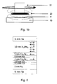
- FIGS. 1 a and 1b show two basic arrangements in which the revolution counter according to the invention described in more detail below can be used.
- Fig. 1a a cross section through an overall system with a decentralized arrangement (hollow shaft sensor arrangement), consisting of a shaft 01 with a circumferentially mounted magnet system 20, each consisting of a Si substrate 10 and 10a (advantageously equal to a transmitter containing), on each of which a revolution counter 11 according to the invention or 11a.
- a magnetic field acts, from the outside, here in the form of a permanent magnet combination 20, which generates a rotation of the direction of the magnetic field by 360 ° at the location of the revolution counter 11 when moving past.
- the revolution counters 11 and 11a are geometrically arranged so that the magnetic field of the magnet 20 can always act on only one of the two.
- the revolution counter 11 undergoes a rotation of a magnetic field at the location of the revolution counter 11 by 360 ° in the rotation of the shaft 01, on the circumference of which are located at one point in the example, a plurality of permanent magnets.
- the sensor is only exposed to the magnetic field over a small angular range. Since the state of the domains explained in more detail below changes in this angular range, this angle range must be "hidden" during the measurement. This can be done by a second sensor 11a with evaluation electronics being mounted so that during the rotation of the shaft 01, only one revolution counter is exposed to the rotating magnetic field.
- revolution counters are basically operated in conjunction with an angle sensor, which is not shown here in detail, the location of the rotating magnetic field is known from the signal of the angle sensor and therefore knows which of the revolution counter supplies a valid or invalid signal, ie in that only the signal of the revolution counter not in the moving magnetic field is read out.
- a permanent magnet 20 is attached to the end face of a shaft 01.
- Fig. 1 b in cross section through an overall system with a central arrangement, consisting of a Si substrate, advantageously with evaluation electronics 10, on which the revolution counter 11 according to the invention is located.
- a magnetic field of a located at the end of the shaft 01 permanent magnet 20 which is designed so that the entire revolution counter is detected by said magnetic field, as the exemplary field lines to indicate.
- the revolution counter 11 Upon rotation of the shaft 01 by 360 °, the revolution counter 11 also experiences a 360 ° rotating magnetic field.
- the domain walls themselves move in the revolution counter 11 according to the invention in an arrangement of a plurality of loops described in greater detail below, for example by a structuring process, in which a defined number of domain walls is inscribed by an initialization process also described below.
- the actual domain configurations may be determined by a number of electrical contacts on the loops due to magnetoresistive effects, e.g. GMR (giant magneto-resistance) or tunneling magneto-resistance (TMR) effect, thereby determining the number of revolutions of a magnetic field that moves the domain walls in closed loops.
- GMR giant magneto-resistance
- TMR tunneling magneto-resistance
- the resistance is low when the direction of magnetization in the reference and sensor layers is the same and increases by (6 to 10)% (in the case of the GMR effect) and by (100 to 500)% in the case of the TMR, respectively Effect, when the direction of the two magnetizations is anti-parallel.
- FIG. 2 shows by way of example a layer stack which is to be used for the utilization of the GMR or the TMR effect. It is in Fig. 2 such, known per se layer package shown in cross section.
- the current flows in the direction of the marked magnetization arrows (in the layer plane), the electrical resistance is determined by electrical contacts (not shown here) which are applied at a great distance (100-500 ⁇ m) away from each other.
- Shapes proposed in the invention are based either on loops with inwardly directed tips having a structure allowing for dual number counting or on loops with inwardly directed tips, which are constructed so that they each realize a non-divisional number of revolutions in each loop.
- N> 4096 revolutions
- a large number of countable revolutions can be realized with a relatively small number of loops and converted into user-friendly signals with manageable circuit complexity.
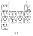
- the basic principle of the present invention is to facilitate understanding of one of the loops of the invention for counting two revolutions using FIG. 3 be explained.
- this loop has two inwardly directed tapered protuberances A.
- the initial configuration upper left illustration in Fig. 3
- the loop with its two peaks is first generated domain-wall-free.
- a configuration line not shown in this figure, a configuration as shown in FIG Fig. 3 shown at the top right.
- This configuration corresponds to the rotation condition -1 ⁇ 4 revolution.
- By small black rectangles are in the individual pictures of the Fig. 3 the domain walls D are shown moving from quarter-turn to quarter-turn through the loop and returning to the initial configuration after exactly two revolutions.
- the central bold arrow marks the direction of the permanent magnet to be detected (not shown here, see component 20 in FIG Fig. 1a and 1b ) and thus the rotating component.
- the in the pictures of the Fig. 3 Thinner arrows indicate the local direction of magnetization in the sensor loop layer.
- 2n-2 peaks exactly n-1 full rotations can be detected.
- the movement of the domains through the loop area without peaks again results in a rotation, so that this arrangement realizes exactly n full revolutions.
- loop combinations Two basic variants of loop combinations are possible, namely a dual structure or a divisional arrangement. What is meant by this is explained below.
- other constructs albeit more difficult to understand, are also within the scope of the invention if an unambiguous assignment of protuberances of moving domains directed in loops with point-shaped inwards is thereby ensured.
- the initial configuration in the dual-system proposed as the first possibility according to the invention is now characterized in that the loop for n revolutions contains exactly n magnetic domain walls which are all adjacent to one another.
- the tips are as pointed as possible form, so that the ratio width / length of the tip is at least 1: 3 and the radius of curvature of the tip itself is kept as small as technologically possible.
- the loop shown here should be able to detect four revolutions and thus, according to the above proviso, provided with six peaks (2n-2) and four adjacent domains are inscribed. For each evaluation, the electrical resistances in the adjacent regions of the peaks marked with a circle are compared. Depending on whether there is a domain in the top or not, the resistances on the right and on the left are equal or unequal and can thus be assigned to the logical value NULL or ONE entered in the loop.
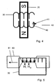
- the current during the erasing operation of the loop generates such a large magnetic field H> H nuk below the track at the location of the loop that there the magnetization, irrespective of the prevailing orientation, is parallel to the magnetic field acting on the sensor layer.
- the magnetic field with the strength H is according to Fig. 4 rotated at least 4 times (for the loop for n turns n times) in one direction (cw or ccw).
- the rotation is stopped when the magnetic field applied to the loop 30 by the permanent magnet 20 coincides in its direction with the direction of the magnetic field 42 generated by the current path 40 in the loop.
- the rotation of the magnetic field moves all the domains present in the loop to the location of the large magnetic field. There they are deleted.
- the return of the interconnect 40 which is guided in an advantageous embodiment at another point on the loop back, it should have a width such that the magnetic field acting below in the plane of the loop, the transport of the domains by the rotating Permanent magnets not hindered. This can typically be achieved by making the return conductor about 5 times as wide as the narrow, large magnetic field generating part of the web 40.
- the desired start configuration (to stay in the example, see loop top right in Fig. 3 ) differs in the direction of magnetization in the left peak.
- FIG. 5 shows one of several possible and conceivable embodiments of Rajstromleitbahn 60, which is guided over the ends of four inwardly directed tips of the loop 30 in the example.
- the electric current I flowing through the additional current conducting path 60 (see arrow 61) generates the magnetic field H I , parallel to this lies a DC field of intensity H M , where H I + H M > H nuk .
- the current flows through thetientstromleitbahn 60, which is tapered in the example in the region of the ends of adjacent tips of the loop 30 and thereby generates a large current density and thus a large magnetic field H I. If a magnetic field H M of the magnitude H min ⁇ H M ⁇ H nuk is present parallel to the flowing current, the magnetizations in the tips, which lie below the narrow region of the additional current conducting path 60, are re-magnetized in the direction of the magnetic field H I, thereby passing through the resulting domains the magnetic field H M transported out of the tips.
- the sandwich 5nm Ni 81 Fe 19 / 1nm Co 90 Fe 10 acts as a soft magnetic layer, through which the domain walls run.
- the NiFe layer will, in practical terms, be thickened considerably (typically 15-20 nm) in order to achieve the so-called shape anisotropy, which essentially results from the ratio thickness / width and the magnetization of the sandwich layer is determined to make big.
- a Py layer and a layer of another soft magnetic alloy for example.
- CoFeNi alloy with a layer thickness between 5 ... 35 nm use.
- the advantage of such an arrangement is that in it the number of projecting into the interior of the loops tips can be kept much smaller than in the dual case considered above, whereby the geometric extent of the loops is further reduced. This advantage, however, comes with a different way of reading the loops.
- the resistance value between the first six mentioned pairs (1-2 to 6-7) is the same and different for the pairs 7-8 and 8-1 because there is a rotation of the loop of 180 ° between the last two mentioned pairs. If there is no domain wall between them, the resistance value is not equal to 1-2 to 6-7 or equal to 7-8 and 8-1.
- a revolution counter constructed according to the dual variant requires several of the loops and tips provided according to the invention, but less electrical contacts for reading and assigning logical states than in a structure of the loop arrangement according to the principle of divisibility, in which the conditions are accurate the other way around, say less loops and tips, but more contacts.
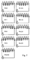
- FIGS. 8 to 11 serve as an example of possible configurations for the provision of electrical contacts.
- the electrical resistances R12 and R34 are measured at the contacts K1 to K4.
- Fig. 9 shows, can be made by merging the contacts K2 and K3 circuitry simplification. The assignment of the resistance values to the logic states takes place in an arbitrarily realizable logic circuit outside the invention, as already mentioned above.
- FIG. 10 shows in the left part of the figure an arrangement of contacts K1 .. K8, wherein four contacts (K1 .. K4) on a horizontal part of the second path and four contacts (K5 .. K8) are arranged on a vertical part of the web.
- the right part of Fig. 10 shows an example of an alternative contact arrangement.
- the contacts for the dual evaluation at K1 to K4 the 90 ° rotated sensor is equal to the loop and is represented by the contacts K5 to K8.
- the reference layer must not be perpendicular to the conductor line in which the resistance is measured.
- This loop means that either the reference direction occupies an oblique, preferably inclined by 45 ° angle to the straight lines in which the resistance is determined occupies.
- a uniform direction of the reference here, without limiting the generality, eg parallel to the web R12, is impressed, and that in a following step, the loop, for example via the contacts K5 to K8, can be heated so far that when a sufficiently large magnetic field, typically 1 T, applies to a local rotation of the reference direction under the local temperature effect.
- the electrical contacts for determining the resistance and thus the direction of the magnetization each left (K1 and K2) and right (K3 and K4) of a peak and the direction of the reference magnetization shows from left to right or vice versa. If you want to locate the domain (or domains) in the whole loop, you must have contacts in all horizontal areas, as in Fig. 11c1 is shown.
- the respective contact pairings thereby detect the changes in resistance which are caused by the domain migration as a result of a rotation of the magnetic field of 180 ° from one contact region to the other.
- the distance of the contacts from each other should, in the case of GMR layer systems, ideally be the same length. In order to keep the number of electrically connected contacts as small as possible, one can contact, as in Fig. 11c3 shown, summarized.
- the contact arrangements such as in Fig. 11c2 shown, so that also Domainwa Wenner can be determined by rotation of the external magnetic field by 180 °. This means that on all horizontal areas of the loop, contacts are placed on the right and left of the tips pointing up or down. If one or more points from the right and / or left side point into the inside of the loop, one of the sides of the tip must be provided with the contacts. Also for this case can be a summary of contacts and thus reducing the number of contacts, as in Fig. 11c4 represented.
- contact K1 is used for R12, contact K4 for R34, contact K5 for R56 and contact K8 for R78 as the upper electrode should (see also Fig. 10 ).
- the lower electrode can be a common contact for all TMR elements.
- the contacts K1, K4, K5 and K8 in which there is a TMR stack between the magnetic wall carrying the domain wall movement, eg an approximately 10 nm thick Ni 81 Fe 19 layer, and the contact, the common contact are located directly on the NiFe layer. However, there may also be a TMR stack between this contact and the NiFe layer.
- the contact surface of this contact should be substantially larger with respect to the NiFe layer.
- the contact surfaces K1, K3, K5 and K7 can be used because the resistance in these TMR elements is indirectly proportional to the area.
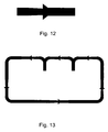
- FIG. 12 schematically shows a local width change, which causes the domains can move in one direction only through this geometric construct.
- a geometry leads to the fact that in a field region H min ⁇ H ⁇ H diode, the domains can only be moved in one direction.
- Such geometrical structures are for such an application in all rectilinear areas of the loops, as in Fig. 13 presented to provide.
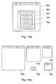
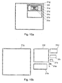
- Figures 14a and 14b . 15a and 15b serve, which illustrate in plan view, for example, each different layouts of the loop assemblies according to the invention, without limiting the invention thereof.
- N 4620
- the individual loops are nested ( Fig. 14a ) or side by side, in each case partially next to one another, on the carrier substrate (10, cf. Fig. 1 a or 1 b) are arranged, as long as only all loop areas from the field of the rotating outer magnet 20 (see also Fig. 1a and 1 b ) are detectable.
- N 128
- the reduction in the expense of attaching the required Contacts, here only at one, in the FIGS. 15 are provided with the length L extended tip-shaped protuberance to be provided at the expense of the increased number of loops compared to the divergent variant according to the Figures 14 ,
- the evaluation electronics can advantageously be formed by a CMOS circuit, which may already contain a Hall angle sensor.
- a further significant advantage of the present invention is that domain states which change upon rotation of an external magnetic field which is capable of changing it can also be detected when the voltage is interrupted, and thus also a rotation carried out in the de-energized state, for example a steering wheel, can be unambiguously displayed.
Landscapes
- Physics & Mathematics (AREA)
- General Physics & Mathematics (AREA)
- Engineering & Computer Science (AREA)
- Computer Hardware Design (AREA)
- Transmission And Conversion Of Sensor Element Output (AREA)
Claims (27)
- Compte-tours magnétique servant à déterminer de façon univoque un nombre de tours prédéterminable d'un élément rotatif devant être déterminé est caractérisé en ce que , en fonction du nombre des tours effectués par l'élément à détecter (01), étant pourvu d'un équipage magnétique (20), dont le champ magnétique permet de saisir tous les capteurs mis en place (30a à 30e , 31a à 31g), les capteurs (30..; 31..) se composent de boucles fermées et guidant des domaines magnétiques (D), ces boucles comprenant au moins une couche ferromagnétique ou magnétique douce, ces boucles présentent à l'intérieur des protubérances (A), se terminant en pointe et orientées vers l'intérieur des boucles, le nombre de protubérances prévues par boucle pouvant varier de boucle en boucle en fonction des divergences d'une boucle à l'autre, les agencements des contacts électriques établis (K..) permettant de saisir les variations de la résistance électrique (R..) des sections de boucles prédéterminable après un changement d'emplacement à des domaines magnétiques, en fonction de l'impact d'un champ magnétique rotatif extérieur de l'équipage magnétique (20) dans des sections de boucles prédéterminées, ces valeurs de résistance mesurées pouvant être fournies à une unité d'évaluation aux fins d'affectation du nombre de tours effectués par l'élément rotatif (01).
- Compte-tours magnétique suivant la revendication 1 est caractérisé en ce que en fonction du nombre croissant prédéterminable de tours à déterminer, il sera possible d'augmenter également le nombre de capteurs en forme de boucles (30..; 31..).
- Compte-tours magnétique selon les revendications 1 et 2 est caractérisé en ce que les capteurs en forme de boucle (30a à 30e; 31a à 31g) sont agencés emboîtée de manière géométrique au substrat (10, 10a).
- Compte-tours magnétique selon les revendications 1 ou 2, est caractérisé en ce que les capteurs en forme de boucles (30a à 30e, 31a à 31g) sont disposés au moins en partie l'un à côté de l'autre sur un substrat (10, 10a).
- Compte-tours magnétique selon l'une des revendications précédentes est caractérisé en ce que le substrat (10, 10a) est un substrat semiconducteur doté d'un dispositif électronique d'évaluation dans lequel la connexion électrique des agencements de contact (K..) prévus sur les éléments de capteur en forme de boucle, est effectuée en direct avec le substrat, de préférence réalisé sous forme de circuits CMOS.
- Compte-tours magnétique selon l'une des revendications précédentes 1 à 4 est caractérisé en ce que la connexion électrique des agencements de contact (K..) prévus sur les capteurs en forme de boucles, avec le dispositif d'évaluation électronique est effectuée au moyen de la technologie Flip-Chip.
- Compte-tours magnétique selon la revendication 1 est caractérisé en ce que dans chacun des capteurs prévus en forme de boucles de détection (30a à 30e; 31a à 31g) est inscrit un nombre fixe déterminé préalable et constant de domaines magnétiques (D).
- Compte-tours magnétique selon la revendication 1 est caractérisé en ce que pour une boucle prévue à compter en nombres entiers n tours de 360°, sont dotées d'exactement 2n-2 de protubérances (A) se terminant en forme pointue et orientées vers l'intérieur des boucles.
- Compte-tours magnétique selon les revendications 1 et 8 est caractérisé en ce que le nombre de protubérances pointues attribué à chaque boucle est défini de sorte que d'une boucle à l'autre le comptage binaire des tours devienne possible.
- Compte-tours magnétique selon la revendication 7 et 9 est caractérisé en ce qu'une des boucles destinées à compter n tours est dotée précisément de 2n-2 de protubérances pointues avec précisément n domaines magnétiques adjacentes.
- Compte-tours magnétique selon les revendications 1 et 8 est caractérisé en ce que le nombre de protubérances pointues attribués à chacune des boucles de capteur est choisi de sorte que le comptage en nombres premiers des tours d'une boucle à l'autre devienne possible.
- Compte-tours magnétique selon la revendication 11 est caractérisé en ce que dans le cas de comptage en nombres premiers de n tours de 360° à travers plusieurs boucles, chacune des boucles comporte au moins deux et au maximum 2n-2 domaines et que la configuration des domaines au sein des boucles ne coïncide avec la configuration initiale des domaines qu'après avoir effectué n tours complets dans le même sens.
- Compte-tours magnétique selon la revendication 1 est caractérisé en ce que dans le cas de comptage de n 360° tours en mi-cycle, est attribué à une boucle un nombre impair de protubérances pointues orientées vers l'intérieur des boucles.
- Compte-tours magnétique selon les revendications 7 et 13 est caractérisé en ce que lors du choix de comptage en nombres premiers n tours de 3600, sont à compter en demi-cycle, chacunes des boucles étant dotées d'au moins une domaine et au maximum autant de domaines que déjà à la fin de n/2 tours effectués dans le même sens, les protubérances pointues et orientées vers l'intérieur des boucles se trouvant disposées sur la boucle, le configuration des domaines au sein des boucles soient égale à la configuration initiale des domaines, cependant l'orientation magnétique des domaines peut être distinguée de la configuration initiale identique à la fin des n/2 tours complets en raison de changement de direction de magnétisation.
- Compte-tours magnétique selon les revendications 9 ou 11 ou 13 est caractérisé en ce que dans la plupart des cas les protubérances pointues situées sur chacune des boucles, ont la même longueur.
- Compte-tours magnétique selon les revendications 1 et 8 est caractérisé en ce que les agencements des contacts électriques prévus (K1 ... K4) sont situés sur chaque côté d'une seule protubérance pointue sur une distance prédéterminable afin de mesurer la résistance électrique.
- Compte-tours magnétique selon les revendications 1 et 8 est caractérisé en ce que les agencements des contacts électriques prévus (K1 ... K4) sont situés sur chaque côté de toute protubérance pointue sur une distance prédéterminable afin de déterminer la résistance électrique.
- Compte-tours magnétique selon la revendication 16 est caractérisé en ce que, en plus des agencements des contacts électriques (K 1 ... K4) dans la zone d'une protubérance pointue au sein de laquelle encore d'autres agencements de contacts (K5, ... K8) sont situés, ladite protubérance pointue sera plus longue par rapport aux autres.
- Compte-tours magnétique selon la revendication 17 est caractérisé en ce que outre les agencements de contacts électriques (K 1 ... K 4) dans la zone région de chaque protubérance pointue, à l'intérieur de chaque protubérance d'autres agencements de contacts (K5, ... K8) sont prévus.
- Compte-tours magnétique selon la revendication 16 et 18 est caractérisé en ce que pour chaque élément de capteur en forme de boucle (31a ... 31g) seulement huit agencements de contacts (K1 ... K8) sont prévus.
- Compte-tours magnétique selon les revendications 17 et 19 est caractérisé en ce que pour chaque élément de capteur en forme de boucle (30) sont prévus au moins 2n agencements de contacts (K...).
- Compte-tours magnétique selon la revendication 21 est caractérisé en ce que pour chaque élément de capteur en forme de boucle (30...) sont prévus au moins 4n agencements de contacts (K...). si en utilisant un seul compteur-tours, on veut prévenir les effets d'hystérèse.
- Compte-tours magnétique selon la revendication 1 est caractérisé en ce que les éléments de capteur en forme de boucle sont formés par un système de couches aux effets GMR.
- Compte-tours magnétique selon la revendication 23 est caractérisé en ce que la couche magnétique douce dans le système aux effets GMR guidant les domaines magnétiques est formée par une couche de NiFe, ou un film d'alliage CoFeNi ou une autre couche d'alliage magnétique douce d'une épaisseur allant de 5 nm à 40 nm et d'une largeur allant de 50 nm à 400 nm.
- Compte-tours magnétique selon la revendication 1 est caractérisé en ce que les éléments de capteur en forme de boucle sont formées par une couche magnétique douce, par exemple par une couche de NiFe, ou d'un film d'alliage CoFeNi ou d'une autre couche d'alliage magnétique douce munies de piles de couches TMR connues.
- Compte-tours magnétique selon la revendication 25 est caractérisé en ce que les piles de couches TMR forment sont à l'origine des agencements des contacts (K...).
- Compte-tours magnétique selon l'une des revendications précédentes est caractérisé en ce que des rétrécissements en forme de cônes allant dans la même direction, sont prévus dans toutes les sections droites des boucles de capteurs afin de permettre aux domaines de pouvoir se déplacer uniquement ans une seule direction, en fonction de l'orientation.
Applications Claiming Priority (2)
| Application Number | Priority Date | Filing Date | Title |
|---|---|---|---|
| DE102007040971 | 2007-08-27 | ||
| PCT/EP2008/006870 WO2009027046A1 (fr) | 2007-08-27 | 2008-08-21 | Compte-tours magnétique |
Publications (2)
| Publication Number | Publication Date |
|---|---|
| EP2191237A1 EP2191237A1 (fr) | 2010-06-02 |
| EP2191237B1 true EP2191237B1 (fr) | 2014-03-26 |
Family
ID=40079707
Family Applications (1)
| Application Number | Title | Priority Date | Filing Date |
|---|---|---|---|
| EP08801647.2A Active EP2191237B1 (fr) | 2007-08-27 | 2008-08-21 | Compte-tours magnétique |
Country Status (5)
| Country | Link |
|---|---|
| US (1) | US8179130B2 (fr) |
| EP (1) | EP2191237B1 (fr) |
| CN (1) | CN101836087B (fr) |
| DE (1) | DE102008037975A1 (fr) |
| WO (1) | WO2009027046A1 (fr) |
Families Citing this family (25)
| Publication number | Priority date | Publication date | Assignee | Title |
|---|---|---|---|---|
| DE102010010893B4 (de) * | 2009-03-10 | 2013-04-11 | Horst Siedle Gmbh & Co. Kg | Elektrische Schaltung insbesondere für einen Umdrehungszähler |
| DE102010022611B4 (de) | 2010-06-01 | 2015-02-19 | Leibniz-Institut für Photonische Technologien e. V. | Magnetischer Umdrehungszähler |
| DE102011080050B4 (de) | 2011-07-28 | 2014-10-23 | Horst Siedle Gmbh & Co. Kg | Elektrische Schaltung, insbesondere für einen Umdrehungszähler |
| DE102012209715A1 (de) | 2012-06-11 | 2013-12-12 | Horst Siedle Gmbh & Co. Kg | Seilzuglängengeber |
| CN202974369U (zh) * | 2012-08-24 | 2013-06-05 | 江苏多维科技有限公司 | 直读式计量装置和直读式水表 |
| DE102013018680B4 (de) | 2013-11-04 | 2022-05-25 | Leibniz-Institut für Photonische Technologien e. V. | Magnetischer Sensor zur absoluten Zählung von Umdrehungen oder linearen Wegstrecken |
| PL3387388T3 (pl) * | 2015-12-11 | 2021-10-11 | Leibniz-Institut Für Photonische Technologien E.V. | Magnetyczny licznik obrotów i sposób określania liczby obrotów, które mogą być określone za pomocą wspomnianego licznika obrotów |
| PL3387387T3 (pl) * | 2015-12-11 | 2020-07-13 | Leibniz-Institut Für Photonische Technologien E.V. | Magnetyczny licznik obrotów do samoczynnego wykrywania stanu błędów przy oznaczaniu wartości obrotowych określanych przez ten licznik obrotów |
| US10782153B2 (en) | 2016-03-08 | 2020-09-22 | Analog Devices Global | Multiturn sensor arrangement and readout |
| DE102016212173A1 (de) * | 2016-07-05 | 2018-01-11 | Schaeffler Technologies AG & Co. KG | Verfahren und Vorrichtung zur Ermittlung einer Umdrehungszahl und einer Winkelposition eines um eine Drehachse verdrehbaren Bauteils |
| DE102016214948A1 (de) * | 2016-08-11 | 2018-02-15 | Schaeffler Technologies AG & Co. KG | Verfahren zum Justieren einer Aktuatoreinrichtung mit einer Magnetsensorvorrichtung und einem Aktuator und Aktuatoreinrichtung mit einem Aktuator und einer Magnetsensorvorrichtung |
| DE102016219211A1 (de) * | 2016-10-04 | 2018-04-05 | Schaeffler Technologies AG & Co. KG | Verfahren zur absoluten Positionsbestimmung, Elektromotor und Betätigungseinrichtung für eine Reibungskupplung |
| JP2018072022A (ja) * | 2016-10-25 | 2018-05-10 | クノールブレムゼ商用車システムジャパン株式会社 | 回転検出装置、ギアシフトユニット及びトランスミッションシステム |
| JP2018072021A (ja) * | 2016-10-25 | 2018-05-10 | クノールブレムゼ商用車システムジャパン株式会社 | 回転検出装置、ギアシフトユニット及びトランスミッションシステム |
| CN107941247A (zh) * | 2017-12-18 | 2018-04-20 | 嘉兴市锐鹰传感技术有限公司 | 一种被动唤醒式多圈编码器及工作方法 |
| US10724844B2 (en) | 2017-12-22 | 2020-07-28 | Infineon Technologies Ag | Multi-turn counter sensor |
| US11614341B2 (en) | 2018-06-14 | 2023-03-28 | Analog Devices International Unlimited Company | Methods and devices for using multi-turn magnetic sensors with extended magnetic windows |
| US11460521B2 (en) | 2019-03-18 | 2022-10-04 | Analog Devices International Unlimited Company | Multiturn sensor arrangement |
| DE102019119670A1 (de) | 2019-07-19 | 2021-01-21 | Infineon Technologies Ag | Umdrehungszähler und Abtasten eines Drehwinkels |
| DE102019218351A1 (de) * | 2019-11-27 | 2021-05-27 | Dr. Johannes Heidenhain Gesellschaft Mit Beschränkter Haftung | Sensorelement zur Speicherung von Umdrehungs- oder Positionsinformationen |
| JP7646826B2 (ja) | 2020-11-20 | 2025-03-17 | アナログ・ディヴァイシス・インターナショナル・アンリミテッド・カンパニー | 磁気感知デバイス |
| CN112493948B (zh) * | 2020-11-30 | 2024-04-12 | 追觅创新科技(苏州)有限公司 | 自清洁设备及清洁组件检测方法 |
| DE102021205136A1 (de) | 2021-05-20 | 2022-11-24 | Dr. Johannes Heidenhain Gmbh | Speichersystem mit einem sensorelement zur speicherung von umdrehungs- oder positionsinformationen |
| DE102021205132A1 (de) | 2021-05-20 | 2022-11-24 | Dr. Johannes Heidenhain Gmbh | Sensorelement zur speicherung von umdrehungs- oder positionsinformationen und speichersystem mit einem sensorelement |
| DE102021004187B3 (de) * | 2021-08-12 | 2022-06-30 | Horst Siedle Gmbh & Co. Kg. | Umdrehungszähler unter Verwendung magnetischer Domänenwandleitbahnen, die schleifenartig verwunden und in sich geschlossen ausgeführt sind |
Family Cites Families (4)
| Publication number | Priority date | Publication date | Assignee | Title |
|---|---|---|---|---|
| DE59914958D1 (de) | 1998-08-20 | 2009-03-26 | Continental Automotive Gmbh | Passiver GMR-Sensor für Antiblockierbremssysteme |
| GB0304610D0 (en) * | 2003-02-28 | 2003-04-02 | Eastgate Invest Ltd | Magnetic logic system |
| DE102004020149A1 (de) | 2004-04-24 | 2005-11-24 | Horst Siedle Gmbh & Co. Kg. | Sensorelement für einen Umdrehungszähler |
| KR20080058332A (ko) * | 2005-08-03 | 2008-06-25 | 인제니아 테크놀러지 리미티드 | 메모리 액세스 |
-
2008
- 2008-08-21 CN CN2008801132299A patent/CN101836087B/zh not_active Expired - Fee Related
- 2008-08-21 WO PCT/EP2008/006870 patent/WO2009027046A1/fr not_active Ceased
- 2008-08-21 DE DE102008037975A patent/DE102008037975A1/de not_active Withdrawn
- 2008-08-21 EP EP08801647.2A patent/EP2191237B1/fr active Active
- 2008-08-21 US US12/675,653 patent/US8179130B2/en active Active
Also Published As
| Publication number | Publication date |
|---|---|
| CN101836087A (zh) | 2010-09-15 |
| US8179130B2 (en) | 2012-05-15 |
| DE102008037975A1 (de) | 2009-03-05 |
| CN101836087B (zh) | 2012-06-13 |
| EP2191237A1 (fr) | 2010-06-02 |
| WO2009027046A1 (fr) | 2009-03-05 |
| US20100301842A1 (en) | 2010-12-02 |
Similar Documents
| Publication | Publication Date | Title |
|---|---|---|
| EP2191237B1 (fr) | Compte-tours magnétique | |
| EP3066421B1 (fr) | Capteur magnétique pour recensement absolu de rotations ou de distances lineaires | |
| DE102010022611B4 (de) | Magnetischer Umdrehungszähler | |
| EP3387388B1 (fr) | Compte-tours magnétique et procédé de détermination du nombre de tours pouvant être détecté par ce compte-tours | |
| DE102017124542B4 (de) | Magnetfeldsensoranordnung und verfahren zum messen eines externen magnetfelds | |
| EP0852700B1 (fr) | Systeme de detection sans contact de la position d'un objet et utilisation dudit dispositif | |
| DE102007032867B4 (de) | Magnetoresistive Magnetfeldsensorstrukturen und Herstellungsverfahren | |
| DE60015612T2 (de) | Messvorrichtung mit magnetoresistiven elektroden | |
| EP0674770B1 (fr) | Detecteur magneto-resistif comportant des couches de mesure raccourcies | |
| EP3387387A1 (fr) | Compte-tours magnétique pour la détection automatique d'états d'erreur lors de la détermination de nombres de tours déterminables avec ce compte-tours | |
| DE102008063226A1 (de) | Magnetischer Umdrehungszähler | |
| DE102016112008A1 (de) | Magnetsensorbauelement und magneterfassungsverfahren | |
| DE102020200177A1 (de) | Streufeldrobuster xmr-sensor mit senkrechter anisotropie | |
| DE102007007764A1 (de) | Drehgeber und Verfahren zu dessen Betrieb | |
| DE19649265A1 (de) | GMR-Sensor mit neuartiger Wheatstonebrücke | |
| DE19532674C1 (de) | Drehwinkelgeber unter Verwendung von Giant Magnetowiderstandsmaterialien | |
| DE102017005562B4 (de) | Magnetischer Umdrehungszähler | |
| DE60023835T2 (de) | Magnetwiderstandssensor oder speicherelement mit vermindertem magnetischen schaltfeld | |
| DE102016103348A1 (de) | Magnetsensor und magnetischer Codierer | |
| DE19949714A1 (de) | Magnetisch sensitives Bauteil, insbesondere Sensorelement, mit magnetoresistiven Schichtsystemen in Brückenschaltung | |
| DE102007032379B4 (de) | Magnettransistorstruktur | |
| WO2002082111A1 (fr) | Procede servant a reguler la magnetisation dans une structure en couches, et sa mise en oeuvre | |
| EP1321743B1 (fr) | Système pour mesurer une longueur absolue comprenant une barre de mesure qui se déplace relativement par rapport à des sondes de longueur mutuellement espacées | |
| EP0867692B1 (fr) | Dispositif de détection sans contact de la position d'un objet et utilisation dudit dispositif | |
| WO2001018816A1 (fr) | Ensemble cellules de memoire et procede permettant de faire fonctionner ledit ensemble |
Legal Events
| Date | Code | Title | Description |
|---|---|---|---|
| PUAI | Public reference made under article 153(3) epc to a published international application that has entered the european phase |
Free format text: ORIGINAL CODE: 0009012 |
|
| 17P | Request for examination filed |
Effective date: 20100224 |
|
| AK | Designated contracting states |
Kind code of ref document: A1 Designated state(s): AT BE BG CH CY CZ DE DK EE ES FI FR GB GR HR HU IE IS IT LI LT LU LV MC MT NL NO PL PT RO SE SI SK TR |
|
| AX | Request for extension of the european patent |
Extension state: AL BA MK RS |
|
| DAX | Request for extension of the european patent (deleted) | ||
| REG | Reference to a national code |
Ref country code: DE Ref legal event code: R079 Ref document number: 502008011510 Country of ref document: DE Free format text: PREVIOUS MAIN CLASS: G01D0005160000 Ipc: G01D0005140000 |
|
| RIC1 | Information provided on ipc code assigned before grant |
Ipc: G11C 11/16 20060101ALI20131008BHEP Ipc: G01D 5/14 20060101AFI20131008BHEP Ipc: G11C 19/08 20060101ALI20131008BHEP |
|
| GRAP | Despatch of communication of intention to grant a patent |
Free format text: ORIGINAL CODE: EPIDOSNIGR1 |
|
| INTG | Intention to grant announced |
Effective date: 20131203 |
|
| GRAS | Grant fee paid |
Free format text: ORIGINAL CODE: EPIDOSNIGR3 |
|
| GRAA | (expected) grant |
Free format text: ORIGINAL CODE: 0009210 |
|
| AK | Designated contracting states |
Kind code of ref document: B1 Designated state(s): AT BE BG CH CY CZ DE DK EE ES FI FR GB GR HR HU IE IS IT LI LT LU LV MC MT NL NO PL PT RO SE SI SK TR |
|
| REG | Reference to a national code |
Ref country code: GB Ref legal event code: FG4D Free format text: NOT ENGLISH |
|
| REG | Reference to a national code |
Ref country code: CH Ref legal event code: EP |
|
| REG | Reference to a national code |
Ref country code: AT Ref legal event code: REF Ref document number: 659222 Country of ref document: AT Kind code of ref document: T Effective date: 20140415 |
|
| REG | Reference to a national code |
Ref country code: IE Ref legal event code: FG4D Free format text: LANGUAGE OF EP DOCUMENT: GERMAN |
|
| REG | Reference to a national code |
Ref country code: DE Ref legal event code: R096 Ref document number: 502008011510 Country of ref document: DE Effective date: 20140508 |
|
| PG25 | Lapsed in a contracting state [announced via postgrant information from national office to epo] |
Ref country code: LT Free format text: LAPSE BECAUSE OF FAILURE TO SUBMIT A TRANSLATION OF THE DESCRIPTION OR TO PAY THE FEE WITHIN THE PRESCRIBED TIME-LIMIT Effective date: 20140326 Ref country code: NO Free format text: LAPSE BECAUSE OF FAILURE TO SUBMIT A TRANSLATION OF THE DESCRIPTION OR TO PAY THE FEE WITHIN THE PRESCRIBED TIME-LIMIT Effective date: 20140626 |
|
| REG | Reference to a national code |
Ref country code: NL Ref legal event code: VDEP Effective date: 20140326 |
|
| REG | Reference to a national code |
Ref country code: LT Ref legal event code: MG4D |
|
| PG25 | Lapsed in a contracting state [announced via postgrant information from national office to epo] |
Ref country code: FI Free format text: LAPSE BECAUSE OF FAILURE TO SUBMIT A TRANSLATION OF THE DESCRIPTION OR TO PAY THE FEE WITHIN THE PRESCRIBED TIME-LIMIT Effective date: 20140326 Ref country code: SE Free format text: LAPSE BECAUSE OF FAILURE TO SUBMIT A TRANSLATION OF THE DESCRIPTION OR TO PAY THE FEE WITHIN THE PRESCRIBED TIME-LIMIT Effective date: 20140326 |
|
| REG | Reference to a national code |
Ref country code: DE Ref legal event code: R082 Ref document number: 502008011510 Country of ref document: DE Representative=s name: PATENTANWALTSBUERO PFEIFFER & KOLLEGEN GBR, DE |
|
| PG25 | Lapsed in a contracting state [announced via postgrant information from national office to epo] |
Ref country code: HR Free format text: LAPSE BECAUSE OF FAILURE TO SUBMIT A TRANSLATION OF THE DESCRIPTION OR TO PAY THE FEE WITHIN THE PRESCRIBED TIME-LIMIT Effective date: 20140326 Ref country code: LV Free format text: LAPSE BECAUSE OF FAILURE TO SUBMIT A TRANSLATION OF THE DESCRIPTION OR TO PAY THE FEE WITHIN THE PRESCRIBED TIME-LIMIT Effective date: 20140326 |
|
| REG | Reference to a national code |
Ref country code: DE Ref legal event code: R081 Ref document number: 502008011510 Country of ref document: DE Owner name: LEIBNIZ-INSTITUT FUER PHOTONISCHE TECHNOLOGIEN, DE Free format text: FORMER OWNERS: HORST SIEDLE GMBH & CO. KG, 78120 FURTWANGEN, DE; INSTITUT FUER PHOTONISCHE TECHNOLOGIEN E.V., 07745 JENA, DE Effective date: 20140904 Ref country code: DE Ref legal event code: R081 Ref document number: 502008011510 Country of ref document: DE Owner name: HORST SIEDLE GMBH & CO. KG, DE Free format text: FORMER OWNERS: HORST SIEDLE GMBH & CO. KG, 78120 FURTWANGEN, DE; INSTITUT FUER PHOTONISCHE TECHNOLOGIEN E.V., 07745 JENA, DE Effective date: 20140904 Ref country code: DE Ref legal event code: R081 Ref document number: 502008011510 Country of ref document: DE Owner name: LEIBNIZ-INSTITUT FUER PHOTONISCHE TECHNOLOGIEN, DE Free format text: FORMER OWNER: HORST SIEDLE GMBH & CO. KG, INSTITUT FUER PHOTONISCHE TECHNO, , DE Effective date: 20140904 Ref country code: DE Ref legal event code: R081 Ref document number: 502008011510 Country of ref document: DE Owner name: HORST SIEDLE GMBH & CO. KG, DE Free format text: FORMER OWNER: HORST SIEDLE GMBH & CO. KG, INSTITUT FUER PHOTONISCHE TECHNO, , DE Effective date: 20140904 Ref country code: DE Ref legal event code: R082 Ref document number: 502008011510 Country of ref document: DE Representative=s name: PATENTANWALTSBUERO PFEIFFER & KOLLEGEN GBR, DE Effective date: 20140904 |
|
| PG25 | Lapsed in a contracting state [announced via postgrant information from national office to epo] |
Ref country code: CZ Free format text: LAPSE BECAUSE OF FAILURE TO SUBMIT A TRANSLATION OF THE DESCRIPTION OR TO PAY THE FEE WITHIN THE PRESCRIBED TIME-LIMIT Effective date: 20140326 Ref country code: CY Free format text: LAPSE BECAUSE OF FAILURE TO SUBMIT A TRANSLATION OF THE DESCRIPTION OR TO PAY THE FEE WITHIN THE PRESCRIBED TIME-LIMIT Effective date: 20140326 Ref country code: IS Free format text: LAPSE BECAUSE OF FAILURE TO SUBMIT A TRANSLATION OF THE DESCRIPTION OR TO PAY THE FEE WITHIN THE PRESCRIBED TIME-LIMIT Effective date: 20140726 Ref country code: EE Free format text: LAPSE BECAUSE OF FAILURE TO SUBMIT A TRANSLATION OF THE DESCRIPTION OR TO PAY THE FEE WITHIN THE PRESCRIBED TIME-LIMIT Effective date: 20140326 Ref country code: NL Free format text: LAPSE BECAUSE OF FAILURE TO SUBMIT A TRANSLATION OF THE DESCRIPTION OR TO PAY THE FEE WITHIN THE PRESCRIBED TIME-LIMIT Effective date: 20140326 Ref country code: BG Free format text: LAPSE BECAUSE OF FAILURE TO SUBMIT A TRANSLATION OF THE DESCRIPTION OR TO PAY THE FEE WITHIN THE PRESCRIBED TIME-LIMIT Effective date: 20140626 Ref country code: RO Free format text: LAPSE BECAUSE OF FAILURE TO SUBMIT A TRANSLATION OF THE DESCRIPTION OR TO PAY THE FEE WITHIN THE PRESCRIBED TIME-LIMIT Effective date: 20140326 |
|
| PG25 | Lapsed in a contracting state [announced via postgrant information from national office to epo] |
Ref country code: PL Free format text: LAPSE BECAUSE OF FAILURE TO SUBMIT A TRANSLATION OF THE DESCRIPTION OR TO PAY THE FEE WITHIN THE PRESCRIBED TIME-LIMIT Effective date: 20140326 Ref country code: ES Free format text: LAPSE BECAUSE OF FAILURE TO SUBMIT A TRANSLATION OF THE DESCRIPTION OR TO PAY THE FEE WITHIN THE PRESCRIBED TIME-LIMIT Effective date: 20140326 Ref country code: SK Free format text: LAPSE BECAUSE OF FAILURE TO SUBMIT A TRANSLATION OF THE DESCRIPTION OR TO PAY THE FEE WITHIN THE PRESCRIBED TIME-LIMIT Effective date: 20140326 |
|
| PG25 | Lapsed in a contracting state [announced via postgrant information from national office to epo] |
Ref country code: PT Free format text: LAPSE BECAUSE OF FAILURE TO SUBMIT A TRANSLATION OF THE DESCRIPTION OR TO PAY THE FEE WITHIN THE PRESCRIBED TIME-LIMIT Effective date: 20140728 |
|
| REG | Reference to a national code |
Ref country code: DE Ref legal event code: R097 Ref document number: 502008011510 Country of ref document: DE |
|
| PG25 | Lapsed in a contracting state [announced via postgrant information from national office to epo] |
Ref country code: DK Free format text: LAPSE BECAUSE OF FAILURE TO SUBMIT A TRANSLATION OF THE DESCRIPTION OR TO PAY THE FEE WITHIN THE PRESCRIBED TIME-LIMIT Effective date: 20140326 |
|
| PLBE | No opposition filed within time limit |
Free format text: ORIGINAL CODE: 0009261 |
|
| STAA | Information on the status of an ep patent application or granted ep patent |
Free format text: STATUS: NO OPPOSITION FILED WITHIN TIME LIMIT |
|
| 26N | No opposition filed |
Effective date: 20150106 |
|
| PG25 | Lapsed in a contracting state [announced via postgrant information from national office to epo] |
Ref country code: LU Free format text: LAPSE BECAUSE OF FAILURE TO SUBMIT A TRANSLATION OF THE DESCRIPTION OR TO PAY THE FEE WITHIN THE PRESCRIBED TIME-LIMIT Effective date: 20140821 Ref country code: IT Free format text: LAPSE BECAUSE OF FAILURE TO SUBMIT A TRANSLATION OF THE DESCRIPTION OR TO PAY THE FEE WITHIN THE PRESCRIBED TIME-LIMIT Effective date: 20140326 Ref country code: MC Free format text: LAPSE BECAUSE OF FAILURE TO SUBMIT A TRANSLATION OF THE DESCRIPTION OR TO PAY THE FEE WITHIN THE PRESCRIBED TIME-LIMIT Effective date: 20140326 |
|
| REG | Reference to a national code |
Ref country code: CH Ref legal event code: PL |
|
| REG | Reference to a national code |
Ref country code: DE Ref legal event code: R097 Ref document number: 502008011510 Country of ref document: DE Effective date: 20150106 |
|
| GBPC | Gb: european patent ceased through non-payment of renewal fee |
Effective date: 20140821 |
|
| PG25 | Lapsed in a contracting state [announced via postgrant information from national office to epo] |
Ref country code: BE Free format text: LAPSE BECAUSE OF NON-PAYMENT OF DUE FEES Effective date: 20140831 Ref country code: LI Free format text: LAPSE BECAUSE OF NON-PAYMENT OF DUE FEES Effective date: 20140831 Ref country code: CH Free format text: LAPSE BECAUSE OF NON-PAYMENT OF DUE FEES Effective date: 20140831 |
|
| REG | Reference to a national code |
Ref country code: IE Ref legal event code: MM4A |
|
| REG | Reference to a national code |
Ref country code: FR Ref legal event code: ST Effective date: 20150430 |
|
| PG25 | Lapsed in a contracting state [announced via postgrant information from national office to epo] |
Ref country code: SI Free format text: LAPSE BECAUSE OF FAILURE TO SUBMIT A TRANSLATION OF THE DESCRIPTION OR TO PAY THE FEE WITHIN THE PRESCRIBED TIME-LIMIT Effective date: 20140326 Ref country code: GB Free format text: LAPSE BECAUSE OF NON-PAYMENT OF DUE FEES Effective date: 20140821 |
|
| PG25 | Lapsed in a contracting state [announced via postgrant information from national office to epo] |
Ref country code: IE Free format text: LAPSE BECAUSE OF NON-PAYMENT OF DUE FEES Effective date: 20140821 Ref country code: FR Free format text: LAPSE BECAUSE OF NON-PAYMENT OF DUE FEES Effective date: 20140901 |
|
| REG | Reference to a national code |
Ref country code: AT Ref legal event code: MM01 Ref document number: 659222 Country of ref document: AT Kind code of ref document: T Effective date: 20140821 |
|
| PG25 | Lapsed in a contracting state [announced via postgrant information from national office to epo] |
Ref country code: AT Free format text: LAPSE BECAUSE OF NON-PAYMENT OF DUE FEES Effective date: 20140821 |
|
| PG25 | Lapsed in a contracting state [announced via postgrant information from national office to epo] |
Ref country code: GR Free format text: LAPSE BECAUSE OF FAILURE TO SUBMIT A TRANSLATION OF THE DESCRIPTION OR TO PAY THE FEE WITHIN THE PRESCRIBED TIME-LIMIT Effective date: 20140627 Ref country code: MT Free format text: LAPSE BECAUSE OF FAILURE TO SUBMIT A TRANSLATION OF THE DESCRIPTION OR TO PAY THE FEE WITHIN THE PRESCRIBED TIME-LIMIT Effective date: 20140326 |
|
| PG25 | Lapsed in a contracting state [announced via postgrant information from national office to epo] |
Ref country code: HU Free format text: LAPSE BECAUSE OF FAILURE TO SUBMIT A TRANSLATION OF THE DESCRIPTION OR TO PAY THE FEE WITHIN THE PRESCRIBED TIME-LIMIT; INVALID AB INITIO Effective date: 20080821 Ref country code: TR Free format text: LAPSE BECAUSE OF FAILURE TO SUBMIT A TRANSLATION OF THE DESCRIPTION OR TO PAY THE FEE WITHIN THE PRESCRIBED TIME-LIMIT Effective date: 20140326 |
|
| PGFP | Annual fee paid to national office [announced via postgrant information from national office to epo] |
Ref country code: DE Payment date: 20250815 Year of fee payment: 18 |