EP2191237B1 - Magnetic revolution counter - Google Patents
Magnetic revolution counter Download PDFInfo
- Publication number
- EP2191237B1 EP2191237B1 EP08801647.2A EP08801647A EP2191237B1 EP 2191237 B1 EP2191237 B1 EP 2191237B1 EP 08801647 A EP08801647 A EP 08801647A EP 2191237 B1 EP2191237 B1 EP 2191237B1
- Authority
- EP
- European Patent Office
- Prior art keywords
- loop
- magnetic
- revolution counter
- accordance
- revolutions
- Prior art date
- Legal status (The legal status is an assumption and is not a legal conclusion. Google has not performed a legal analysis and makes no representation as to the accuracy of the status listed.)
- Active
Links
Images


Classifications
-
- G—PHYSICS
- G01—MEASURING; TESTING
- G01D—MEASURING NOT SPECIALLY ADAPTED FOR A SPECIFIC VARIABLE; ARRANGEMENTS FOR MEASURING TWO OR MORE VARIABLES NOT COVERED IN A SINGLE OTHER SUBCLASS; TARIFF METERING APPARATUS; MEASURING OR TESTING NOT OTHERWISE PROVIDED FOR
- G01D5/00—Mechanical means for transferring the output of a sensing member; Means for converting the output of a sensing member to another variable where the form or nature of the sensing member does not constrain the means for converting; Transducers not specially adapted for a specific variable
- G01D5/12—Mechanical means for transferring the output of a sensing member; Means for converting the output of a sensing member to another variable where the form or nature of the sensing member does not constrain the means for converting; Transducers not specially adapted for a specific variable using electric or magnetic means
- G01D5/14—Mechanical means for transferring the output of a sensing member; Means for converting the output of a sensing member to another variable where the form or nature of the sensing member does not constrain the means for converting; Transducers not specially adapted for a specific variable using electric or magnetic means influencing the magnitude of a current or voltage
- G01D5/142—Mechanical means for transferring the output of a sensing member; Means for converting the output of a sensing member to another variable where the form or nature of the sensing member does not constrain the means for converting; Transducers not specially adapted for a specific variable using electric or magnetic means influencing the magnitude of a current or voltage using Hall-effect devices
- G01D5/145—Mechanical means for transferring the output of a sensing member; Means for converting the output of a sensing member to another variable where the form or nature of the sensing member does not constrain the means for converting; Transducers not specially adapted for a specific variable using electric or magnetic means influencing the magnitude of a current or voltage using Hall-effect devices influenced by the relative movement between the Hall device and magnetic fields
-
- G—PHYSICS
- G11—INFORMATION STORAGE
- G11C—STATIC STORES
- G11C11/00—Digital stores characterised by the use of particular electric or magnetic storage elements; Storage elements therefor
- G11C11/02—Digital stores characterised by the use of particular electric or magnetic storage elements; Storage elements therefor using magnetic elements
- G11C11/16—Digital stores characterised by the use of particular electric or magnetic storage elements; Storage elements therefor using magnetic elements using elements in which the storage effect is based on magnetic spin effect
- G11C11/161—Digital stores characterised by the use of particular electric or magnetic storage elements; Storage elements therefor using magnetic elements using elements in which the storage effect is based on magnetic spin effect details concerning the memory cell structure, e.g. the layers of the ferromagnetic memory cell
-
- G—PHYSICS
- G11—INFORMATION STORAGE
- G11C—STATIC STORES
- G11C19/00—Digital stores in which the information is moved stepwise, e.g. shift registers
- G11C19/02—Digital stores in which the information is moved stepwise, e.g. shift registers using magnetic elements
- G11C19/08—Digital stores in which the information is moved stepwise, e.g. shift registers using magnetic elements using thin films in plane structure
- G11C19/0808—Digital stores in which the information is moved stepwise, e.g. shift registers using magnetic elements using thin films in plane structure using magnetic domain propagation
-
- G—PHYSICS
- G01—MEASURING; TESTING
- G01D—MEASURING NOT SPECIALLY ADAPTED FOR A SPECIFIC VARIABLE; ARRANGEMENTS FOR MEASURING TWO OR MORE VARIABLES NOT COVERED IN A SINGLE OTHER SUBCLASS; TARIFF METERING APPARATUS; MEASURING OR TESTING NOT OTHERWISE PROVIDED FOR
- G01D2205/00—Indexing scheme relating to details of means for transferring or converting the output of a sensing member
- G01D2205/20—Detecting rotary movement
- G01D2205/26—Details of encoders or position sensors specially adapted to detect rotation beyond a full turn of 360°, e.g. multi-rotation
Definitions
- the invention relates to a magnetic revolution counter for the unambiguous determination of a predeterminable number of rotations of a rotating element to be determined, which can advantageously be used in a variety of fields of technology, in particular in the automotive industry.
- Sensors for determining an angular position are widely used. Common to them is that the sensor signal is periodic after 360 °, ie that the sensor can not distinguish between 10 ° and 370 °. Therefore, such sensors for tasks in which beyond the 360 °, the angle must be determined, as is the case for example in the steering wheel in the car, combined with another sensor, which must be able to detect the number of revolutions , In combination with a revolution counter it is possible to differentiate between 10 ° and 370 °. To determine the number of revolutions, solutions are known in which mechanical conclusions can be drawn about the course of a spiral with N spiral arms on the number of revolutions (for example between 1 and 5). Other solutions use mechanical transmissions in conjunction with two angle sensors.
- the angle can also be determined, for example, from 0 to 5 ⁇ 360 °. All these solutions have in common that they require a mechanism for the realization, so they are not touch and thus not wear-free. For many applications, especially in the automobile, however, a non-contact solution is required. This could be realized so that one determines (permanently) the angular position at any time and in this way a transition from 359 ° to 360 ° from the angle 0 ° can be distinguished. This assumes that the sensor and an associated memory element are permanently supplied with electrical energy. This contradicts the requirement in the automotive industry, that the determination of the absolute angle in the range of, for example, 0 ° to bspw. 5 - 360 ° must be successful even if, for example, the on-board electronics are disconnected from the battery.
- Another sensor element for counting revolutions that meets the above requirements, is from the EP 1 740 909 B1 ( WO 2005/106395 ) known.
- This sensor element is in the form of an elongated spiral with N turns and consists of a layer stack having the giant magnetoresistance effect (GMR).
- the GMR layer system of this sensor element consists essentially of a hard magnetic layer which defines the reference direction and a soft magnetic layer separated by a non-magnetic intermediate layer.
- the external magnetic field to be detected is strong enough to change the magnetization direction of the soft magnetic layer by moving domain walls, but too weak for one Change in the magnetization direction of the hard magnetic layer, which runs parallel to the straight lines of the elongated spiral.
- the sensor element thus reacts to a rotating magnetic field with a resistance change, within the countable range of 0 to N revolutions whole and half revolutions in the form of 2N + 1 resistance values are registered.
- Each resistance value is uniquely associated with a half-integer or integer revolution value.
- the magnetic structure remains unchanged when the magnetic field does not rotate. During rotation, the magnetization directions change, regardless of whether the resistance value is read out or not. This means that the system also registers all changes in the rotating magnetic field even in a currentless or powerless state and only needs a power supply for readout, ie determination of the resistance.
- Each loop has an outward lead, at the end of which is a magnetoresistive element for reading the information.
- a rotating magnetic field which collects the loops homogeneously, serves as clock and power supply for the transport of the domains and in a special version as a serial data channel.
- Basic principle of this Arrangement is the variable generation of domains whose number corresponds to the concrete information to be stored.
- Object of the present invention is to provide a magnetic sensor system for a revolution counter, which allows a determination of any predetermined number of revolutions, for example.
- N Up to values N> 4000 or specifiable above, and thus, if desired, significantly over previously known solutions goes out and at the same time allows a cheap and structurally small design, which does not adhere to the disadvantages of the prior art.
- each rotation of the object to be monitored is connected to a 360 ° rotation of a magnetic field at the location of a revolution counter and that this 360 ° rotation of the magnetic field leads to a change in the position of magnetic domains which are in one inventive arrangement of defined different loops with directed into the loop interior, tapering protuberances move.
- each loop contains as many adjacent domains as that loop alone should count revolutions.
- a fixed and defined predefinable number of domains are written per loop, which then remain there over the lifetime or until a reformatting of the revolution counter even there, even if the entire assembly is de-energized.
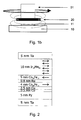
- FIGS. 1 a and 1b show two basic arrangements in which the revolution counter according to the invention described in more detail below can be used.
- Fig. 1a a cross section through an overall system with a decentralized arrangement (hollow shaft sensor arrangement), consisting of a shaft 01 with a circumferentially mounted magnet system 20, each consisting of a Si substrate 10 and 10a (advantageously equal to a transmitter containing), on each of which a revolution counter 11 according to the invention or 11a.
- a magnetic field acts, from the outside, here in the form of a permanent magnet combination 20, which generates a rotation of the direction of the magnetic field by 360 ° at the location of the revolution counter 11 when moving past.
- the revolution counters 11 and 11a are geometrically arranged so that the magnetic field of the magnet 20 can always act on only one of the two.
- the revolution counter 11 undergoes a rotation of a magnetic field at the location of the revolution counter 11 by 360 ° in the rotation of the shaft 01, on the circumference of which are located at one point in the example, a plurality of permanent magnets.
- the sensor is only exposed to the magnetic field over a small angular range. Since the state of the domains explained in more detail below changes in this angular range, this angle range must be "hidden" during the measurement. This can be done by a second sensor 11a with evaluation electronics being mounted so that during the rotation of the shaft 01, only one revolution counter is exposed to the rotating magnetic field.
- revolution counters are basically operated in conjunction with an angle sensor, which is not shown here in detail, the location of the rotating magnetic field is known from the signal of the angle sensor and therefore knows which of the revolution counter supplies a valid or invalid signal, ie in that only the signal of the revolution counter not in the moving magnetic field is read out.
- a permanent magnet 20 is attached to the end face of a shaft 01.
- Fig. 1 b in cross section through an overall system with a central arrangement, consisting of a Si substrate, advantageously with evaluation electronics 10, on which the revolution counter 11 according to the invention is located.
- a magnetic field of a located at the end of the shaft 01 permanent magnet 20 which is designed so that the entire revolution counter is detected by said magnetic field, as the exemplary field lines to indicate.
- the revolution counter 11 Upon rotation of the shaft 01 by 360 °, the revolution counter 11 also experiences a 360 ° rotating magnetic field.
- the domain walls themselves move in the revolution counter 11 according to the invention in an arrangement of a plurality of loops described in greater detail below, for example by a structuring process, in which a defined number of domain walls is inscribed by an initialization process also described below.
- the actual domain configurations may be determined by a number of electrical contacts on the loops due to magnetoresistive effects, e.g. GMR (giant magneto-resistance) or tunneling magneto-resistance (TMR) effect, thereby determining the number of revolutions of a magnetic field that moves the domain walls in closed loops.
- GMR giant magneto-resistance
- TMR tunneling magneto-resistance
- the resistance is low when the direction of magnetization in the reference and sensor layers is the same and increases by (6 to 10)% (in the case of the GMR effect) and by (100 to 500)% in the case of the TMR, respectively Effect, when the direction of the two magnetizations is anti-parallel.
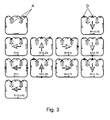
- FIG. 2 shows by way of example a layer stack which is to be used for the utilization of the GMR or the TMR effect. It is in Fig. 2 such, known per se layer package shown in cross section.
- the current flows in the direction of the marked magnetization arrows (in the layer plane), the electrical resistance is determined by electrical contacts (not shown here) which are applied at a great distance (100-500 ⁇ m) away from each other.
- Shapes proposed in the invention are based either on loops with inwardly directed tips having a structure allowing for dual number counting or on loops with inwardly directed tips, which are constructed so that they each realize a non-divisional number of revolutions in each loop.
- N> 4096 revolutions
- a large number of countable revolutions can be realized with a relatively small number of loops and converted into user-friendly signals with manageable circuit complexity.
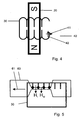
- the basic principle of the present invention is to facilitate understanding of one of the loops of the invention for counting two revolutions using FIG. 3 be explained.
- this loop has two inwardly directed tapered protuberances A.
- the initial configuration upper left illustration in Fig. 3
- the loop with its two peaks is first generated domain-wall-free.
- a configuration line not shown in this figure, a configuration as shown in FIG Fig. 3 shown at the top right.
- This configuration corresponds to the rotation condition -1 ⁇ 4 revolution.
- By small black rectangles are in the individual pictures of the Fig. 3 the domain walls D are shown moving from quarter-turn to quarter-turn through the loop and returning to the initial configuration after exactly two revolutions.
- the central bold arrow marks the direction of the permanent magnet to be detected (not shown here, see component 20 in FIG Fig. 1a and 1b ) and thus the rotating component.
- the in the pictures of the Fig. 3 Thinner arrows indicate the local direction of magnetization in the sensor loop layer.
- 2n-2 peaks exactly n-1 full rotations can be detected.
- the movement of the domains through the loop area without peaks again results in a rotation, so that this arrangement realizes exactly n full revolutions.
- loop combinations Two basic variants of loop combinations are possible, namely a dual structure or a divisional arrangement. What is meant by this is explained below.
- other constructs albeit more difficult to understand, are also within the scope of the invention if an unambiguous assignment of protuberances of moving domains directed in loops with point-shaped inwards is thereby ensured.
- the initial configuration in the dual-system proposed as the first possibility according to the invention is now characterized in that the loop for n revolutions contains exactly n magnetic domain walls which are all adjacent to one another.
- the tips are as pointed as possible form, so that the ratio width / length of the tip is at least 1: 3 and the radius of curvature of the tip itself is kept as small as technologically possible.
- the loop shown here should be able to detect four revolutions and thus, according to the above proviso, provided with six peaks (2n-2) and four adjacent domains are inscribed. For each evaluation, the electrical resistances in the adjacent regions of the peaks marked with a circle are compared. Depending on whether there is a domain in the top or not, the resistances on the right and on the left are equal or unequal and can thus be assigned to the logical value NULL or ONE entered in the loop.
- the current during the erasing operation of the loop generates such a large magnetic field H> H nuk below the track at the location of the loop that there the magnetization, irrespective of the prevailing orientation, is parallel to the magnetic field acting on the sensor layer.
- the magnetic field with the strength H is according to Fig. 4 rotated at least 4 times (for the loop for n turns n times) in one direction (cw or ccw).
- the rotation is stopped when the magnetic field applied to the loop 30 by the permanent magnet 20 coincides in its direction with the direction of the magnetic field 42 generated by the current path 40 in the loop.
- the rotation of the magnetic field moves all the domains present in the loop to the location of the large magnetic field. There they are deleted.
- the return of the interconnect 40 which is guided in an advantageous embodiment at another point on the loop back, it should have a width such that the magnetic field acting below in the plane of the loop, the transport of the domains by the rotating Permanent magnets not hindered. This can typically be achieved by making the return conductor about 5 times as wide as the narrow, large magnetic field generating part of the web 40.
- the desired start configuration (to stay in the example, see loop top right in Fig. 3 ) differs in the direction of magnetization in the left peak.
- FIG. 5 shows one of several possible and conceivable embodiments of Rajstromleitbahn 60, which is guided over the ends of four inwardly directed tips of the loop 30 in the example.
- the electric current I flowing through the additional current conducting path 60 (see arrow 61) generates the magnetic field H I , parallel to this lies a DC field of intensity H M , where H I + H M > H nuk .
- the current flows through thetientstromleitbahn 60, which is tapered in the example in the region of the ends of adjacent tips of the loop 30 and thereby generates a large current density and thus a large magnetic field H I. If a magnetic field H M of the magnitude H min ⁇ H M ⁇ H nuk is present parallel to the flowing current, the magnetizations in the tips, which lie below the narrow region of the additional current conducting path 60, are re-magnetized in the direction of the magnetic field H I, thereby passing through the resulting domains the magnetic field H M transported out of the tips.
- the sandwich 5nm Ni 81 Fe 19 / 1nm Co 90 Fe 10 acts as a soft magnetic layer, through which the domain walls run.
- the NiFe layer will, in practical terms, be thickened considerably (typically 15-20 nm) in order to achieve the so-called shape anisotropy, which essentially results from the ratio thickness / width and the magnetization of the sandwich layer is determined to make big.
- a Py layer and a layer of another soft magnetic alloy for example.
- CoFeNi alloy with a layer thickness between 5 ... 35 nm use.
- the advantage of such an arrangement is that in it the number of projecting into the interior of the loops tips can be kept much smaller than in the dual case considered above, whereby the geometric extent of the loops is further reduced. This advantage, however, comes with a different way of reading the loops.
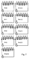
- the resistance value between the first six mentioned pairs (1-2 to 6-7) is the same and different for the pairs 7-8 and 8-1 because there is a rotation of the loop of 180 ° between the last two mentioned pairs. If there is no domain wall between them, the resistance value is not equal to 1-2 to 6-7 or equal to 7-8 and 8-1.
- a revolution counter constructed according to the dual variant requires several of the loops and tips provided according to the invention, but less electrical contacts for reading and assigning logical states than in a structure of the loop arrangement according to the principle of divisibility, in which the conditions are accurate the other way around, say less loops and tips, but more contacts.
- FIGS. 8 to 11 serve as an example of possible configurations for the provision of electrical contacts.
- the electrical resistances R12 and R34 are measured at the contacts K1 to K4.
- Fig. 9 shows, can be made by merging the contacts K2 and K3 circuitry simplification. The assignment of the resistance values to the logic states takes place in an arbitrarily realizable logic circuit outside the invention, as already mentioned above.
- FIG. 10 shows in the left part of the figure an arrangement of contacts K1 .. K8, wherein four contacts (K1 .. K4) on a horizontal part of the second path and four contacts (K5 .. K8) are arranged on a vertical part of the web.
- the right part of Fig. 10 shows an example of an alternative contact arrangement.
- the contacts for the dual evaluation at K1 to K4 the 90 ° rotated sensor is equal to the loop and is represented by the contacts K5 to K8.
- the reference layer must not be perpendicular to the conductor line in which the resistance is measured.
- This loop means that either the reference direction occupies an oblique, preferably inclined by 45 ° angle to the straight lines in which the resistance is determined occupies.
- a uniform direction of the reference here, without limiting the generality, eg parallel to the web R12, is impressed, and that in a following step, the loop, for example via the contacts K5 to K8, can be heated so far that when a sufficiently large magnetic field, typically 1 T, applies to a local rotation of the reference direction under the local temperature effect.
- the electrical contacts for determining the resistance and thus the direction of the magnetization each left (K1 and K2) and right (K3 and K4) of a peak and the direction of the reference magnetization shows from left to right or vice versa. If you want to locate the domain (or domains) in the whole loop, you must have contacts in all horizontal areas, as in Fig. 11c1 is shown.
- the respective contact pairings thereby detect the changes in resistance which are caused by the domain migration as a result of a rotation of the magnetic field of 180 ° from one contact region to the other.
- the distance of the contacts from each other should, in the case of GMR layer systems, ideally be the same length. In order to keep the number of electrically connected contacts as small as possible, one can contact, as in Fig. 11c3 shown, summarized.
- the contact arrangements such as in Fig. 11c2 shown, so that also Domainwa Wenner can be determined by rotation of the external magnetic field by 180 °. This means that on all horizontal areas of the loop, contacts are placed on the right and left of the tips pointing up or down. If one or more points from the right and / or left side point into the inside of the loop, one of the sides of the tip must be provided with the contacts. Also for this case can be a summary of contacts and thus reducing the number of contacts, as in Fig. 11c4 represented.
- contact K1 is used for R12, contact K4 for R34, contact K5 for R56 and contact K8 for R78 as the upper electrode should (see also Fig. 10 ).
- the lower electrode can be a common contact for all TMR elements.
- the contacts K1, K4, K5 and K8 in which there is a TMR stack between the magnetic wall carrying the domain wall movement, eg an approximately 10 nm thick Ni 81 Fe 19 layer, and the contact, the common contact are located directly on the NiFe layer. However, there may also be a TMR stack between this contact and the NiFe layer.
- the contact surface of this contact should be substantially larger with respect to the NiFe layer.
- the contact surfaces K1, K3, K5 and K7 can be used because the resistance in these TMR elements is indirectly proportional to the area.
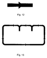
- FIG. 12 schematically shows a local width change, which causes the domains can move in one direction only through this geometric construct.
- a geometry leads to the fact that in a field region H min ⁇ H ⁇ H diode, the domains can only be moved in one direction.
- Such geometrical structures are for such an application in all rectilinear areas of the loops, as in Fig. 13 presented to provide.
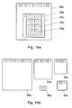
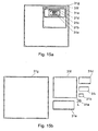
- Figures 14a and 14b . 15a and 15b serve, which illustrate in plan view, for example, each different layouts of the loop assemblies according to the invention, without limiting the invention thereof.
- N 4620
- the individual loops are nested ( Fig. 14a ) or side by side, in each case partially next to one another, on the carrier substrate (10, cf. Fig. 1 a or 1 b) are arranged, as long as only all loop areas from the field of the rotating outer magnet 20 (see also Fig. 1a and 1 b ) are detectable.
- N 128
- the reduction in the expense of attaching the required Contacts, here only at one, in the FIGS. 15 are provided with the length L extended tip-shaped protuberance to be provided at the expense of the increased number of loops compared to the divergent variant according to the Figures 14 ,
- the evaluation electronics can advantageously be formed by a CMOS circuit, which may already contain a Hall angle sensor.
- a further significant advantage of the present invention is that domain states which change upon rotation of an external magnetic field which is capable of changing it can also be detected when the voltage is interrupted, and thus also a rotation carried out in the de-energized state, for example a steering wheel, can be unambiguously displayed.
Landscapes
- Physics & Mathematics (AREA)
- General Physics & Mathematics (AREA)
- Engineering & Computer Science (AREA)
- Computer Hardware Design (AREA)
- Transmission And Conversion Of Sensor Element Output (AREA)
Description
Die Erfindung betrifft einen magnetischen Umdrehungszähler zur eindeutigen Bestimmung einer vorgebbaren Anzahl zu bestimmender Umdrehungen eines rotierenden Elements, der in vielfältigen Gebieten der Technik, insbesondere im Automobilbau vorteilhaft Anwendung finden kann.The invention relates to a magnetic revolution counter for the unambiguous determination of a predeterminable number of rotations of a rotating element to be determined, which can advantageously be used in a variety of fields of technology, in particular in the automotive industry.
Sensoren zur Bestimmung einer Winkellage nach unterschiedlichen physikalischen Prinzipien sind weit verbreitet. Ihnen gemein ist es, dass das Sensorsignal nach 360° periodisch ist, d.h. dass der Sensor nicht zwischen 10° und 370° unterscheiden kann. Deshalb werden derartige Sensoren für Aufgabenstellungen, bei denen über die 360° hinaus der Winkel bestimmt werden muss, wie es z.B. beim Lenkrad im Automobil der Fall ist, kombiniert mit einem weiteren Sensor, der in der Lage sein muss, die Anzahl der Umdrehungen zu detektieren. In Kombination mit einem Umdrehungszähler kann dann zwischen 10° und 370° unterschieden werden. Zur Bestimmung der Anzahl der Umdrehungen sind Lösungen bekannt, bei denen mechanisch über den Gang einer Spirale mit N Spiralenarmen auf die Anzahl der Umdrehungen (bspw. zwischen 1...5) geschlossen werden kann. Andere Lösungen nutzen mechanische Getriebe in Verbindung mit zwei Winkelsensoren. Aus der Kenntnis des Aufbaus des Getriebes und der Winkellage zweier Magneten, die mit unterschiedlichen Rädern des Getriebes verbunden sind, kann der Winkel auch z.B. von 0 bis 5 · 360° bestimmt werden. Allen diesen Lösungen ist es gemein, dass sie zur Realisierung eine Mechanik benötigen, sie also nicht berührungs- und damit nicht verschleißfrei sind. Für viele Anwendungen, insbesondere im Automobil, ist jedoch eine berührungsfreie Lösung erforderlich. Dies könnte so realisiert werden, dass man zu jedem Zeitpunkt (permanent) die Winkellage bestimmt und auf diese Art ein Übergang von 359° auf 360° vom Winkel 0° unterschieden werden kann. Dies setzt voraus, dass der Sensor und ein zugehöriges Speicherelement permanent mit elektrischer Energie versorgt werden. Dies widerspricht der Forderung im Automobilbau, dass die Bestimmung des Absolutwinkels im Bereich von z.B. 0° bis bspw. 5 - 360° auch dann erfolgreich sein muss, wenn z.B. die Bordelektronik von der Batterie abgeklemmt ist.Sensors for determining an angular position according to different physical principles are widely used. Common to them is that the sensor signal is periodic after 360 °, ie that the sensor can not distinguish between 10 ° and 370 °. Therefore, such sensors for tasks in which beyond the 360 °, the angle must be determined, as is the case for example in the steering wheel in the car, combined with another sensor, which must be able to detect the number of revolutions , In combination with a revolution counter it is possible to differentiate between 10 ° and 370 °. To determine the number of revolutions, solutions are known in which mechanical conclusions can be drawn about the course of a spiral with N spiral arms on the number of revolutions (for example between 1 and 5). Other solutions use mechanical transmissions in conjunction with two angle sensors. From the knowledge of the structure of the transmission and the angular position of two magnets, which are connected to different wheels of the transmission, the angle can also be determined, for example, from 0 to 5 · 360 °. All these solutions have in common that they require a mechanism for the realization, so they are not touch and thus not wear-free. For many applications, especially in the automobile, however, a non-contact solution is required. This could be realized so that one determines (permanently) the angular position at any time and in this way a transition from 359 ° to 360 ° from the
Eine berührungsfreie Zählung der Anzahl von Umdrehungen, die diese Forderungen im Prinzip erfüllt, wurde von der Fa. Posital (Firmenmitteilung "Kraftwerk im Encoder..." www.postal.de) entwickelt. Dort wird ein Hallsensor zur Bestimmung des Winkels (0 - 360°) genutzt. Die Messung der Anzahl der Umdrehungen geschieht dort mit Hilfe eines so genannten Wieganddrahtes. Dieser Draht besitzt spezielle magnetische Eigenschaften, die dafür sorgen, dass nach einer jeden Umdrehung durch die dann ablaufende plötzliche Bewegung einer magnetischen Domänenwand durch einen einige Millimeter langen Draht ein kurzer, aber hinreichend intensiver Spannungsimpuls entsteht, der in ein FeRAM (Ferroelektrisches Random Access Memory) eingeschrieben werden kann, auch ohne dass das FeRAM mit der Batterie verbunden ist. Diese Lösung erfüllt damit die Forderung nach der Bestimmung der Anzahl der Umdrehungen verschleiß- und berührungsfrei und zählt auch ohne Anliegen der Stromversorgung Umdrehungen bis zur maximalen Speicherkapazität des eingesetzten FeRAMS. Jedoch wird eine solche Lösung von der Automobilindustrie abgelehnt, da auf Grund der makroskopischen Größe des Wieganddrahtes eine kostengünstige Herstellung und Konfektionierung nicht möglich ist und durch den hochohmigen Eingang der FeRAM's Probleme mit der elektromagnetischen Verträglichkeit bestehen.A non-contact count of the number of revolutions, which fulfills these requirements in principle, was developed by the company Posital (company announcement "power station in the encoder ..." www.postal.de). There, a Hall sensor is used to determine the angle (0 - 360 °). The measurement of the number of revolutions happens there with the help of a so-called Wiegand wire. This wire has special magnetic properties that cause a short but sufficiently intense voltage pulse after every revolution caused by the sudden movement of a magnetic domain wall through a wire a few millimeters long, resulting in a FeRAM (Ferroelectric Random Access Memory). can be written, even without the FeRAM connected to the battery. This solution thus meets the requirement for the determination of the number of revolutions wear and contact-free and counts even without concern of the power supply revolutions up to the maximum storage capacity of the FeRAMS used. However, such a solution is rejected by the automotive industry, as due to the macroscopic size of the Wiegand wire cost-effective production and packaging is not possible and exist through the high-impedance input of FeRAM's problems with the electromagnetic compatibility.
Ein weiteres Sensorelement zur Zählung von Umdrehungen, das die oben genannten Anforderungen erfüllt, ist aus der
Nachteil einer solchen Anordnung ist, dass aufgrund der verwendeten Speichergeometrie, jede Umdrehung benötigt eine komplette Spiralwindung, bei Zählung von einer größeren Anzahl von Umdrehungen, die Spirale geometrisch sehr groß werden muss. Damit steigt einerseits die Wahrscheinlichkeit dafür, dass bei der Herstellung der Spirale auftretende Defekte zu einem Ausfall und damit zu einer Verringerung der Ausbeute führen. Andererseits steigen damit die Chipfläche und somit die Kosten für einen derartigen Sensor. Des Weiteren führt das in
Neben den vorstehend beschriebenen Bestrebungen, Umdrehungszähler auf der Basis sich bewegender Domänenwände zu entwickeln, gibt es auch, obgleich in einem Suchfeld, das fernab vorliegender Erfindung liegt, Vorschläge zur Realisierung einer magnetischen Logik mit Hilfe sich bewegender Domänenwände. Hier werden durch geschlossene oder sich verzweigende magnetische Streifen magnetische Domänen derart bewegt, dass sich logische Funktionen wie AND, NOT und XOR realisieren lassen, außerdem Kreuzungen und Verzweigungen. So schlagen
Aufgabe der vorliegenden Erfindung ist es, ein magnetisches Sensorsystem für einen Umdrehungszähler zu schaffen, das eine Bestimmung einer beliebig vorgebbaren Anzahl von Umdrehungen, bspw. bis zu Werten N > 4000 oder vorgebbar darüber, erlaubt und damit, wenn gewünscht, wesentlich über bisher bekannte Lösungen hinausgeht und zugleich eine preiswerte und konstruktiv kleine Ausführung ermöglicht, welcher nicht die Nachteile des Standes der Technik anhaften.Object of the present invention is to provide a magnetic sensor system for a revolution counter, which allows a determination of any predetermined number of revolutions, for example. Up to values N> 4000 or specifiable above, and thus, if desired, significantly over previously known solutions goes out and at the same time allows a cheap and structurally small design, which does not adhere to the disadvantages of the prior art.
Dabei sollen mit der vorgeschlagenen Lösung wesentliche Nachteile bisheriger Lösungsvorschläge, nämlich die große Anzahl von Kontakten (vgl.
Die Aufgabe wird durch die kennzeichnenden Merkmale des Anspruchs 1 gelöst. Vorteilhafte Ausgestaltungen sind Gegenstand der nachgeordneten Ansprüche. Das Wesen vorliegender Erfindung besteht darin, dass in Abhängigkeit von der Anzahl zu messender Umdrehungen eines zu detektierenden Elements (bspw. einer Welle), welches mit einem Magnetsystem versehen ist, dessen Magnetfeld alle vorgesehenen Sensorelemente zu erfassen gestattet, mehrere solcher vorgesehen sind, wobei die Sensorelemente durch mit magnetischen Domänen besetzte und diese führende, in sich jeweils geschlossene Schleifen gebildet sind, die wenigstens eine ferromagnetische, respektive weichmagnetische Schicht beinhalten, wobei die Schleifen ins Schleifeninnere gerichtete, spitz zulaufende Ausstülpungen aufweisen, die Anzahl der pro Schleife vorgesehenen Ausstülpungen von Schleife zu Schleife voneinander abweichend definiert festgelegt ist und elektrische Kontaktanordnungen an den Schleifen vorgesehen sind, die Veränderungen des elektrischen Widerstands vorgebbarer Schleifenabschnitte nach erfolgtem Ortswechsel magnetischer Domänen, infolge der Einwirkung des äußeren rotierenden Magnetfeldes des Magnetsystems in den vorgegebenen Schleifenabschnitten zu erfassen gestatten und diese Widerstandswerte einer Auswerteeinheit zwecks Zuordnung der Anzahl der Umdrehungen des rotierenden Elements zuführbar sind.The object is solved by the characterizing features of
Die Grundidee vorliegender Erfindung beruht darauf, dass jede Umdrehung des zu überwachenden Objektes mit einer 360° Drehung eines Magnetfeldes am Ort eines Umdrehungszählers verbunden ist und dass diese 360°-Drehung des Magnetfeldes zu einer Änderung der Position von magnetischen Domänen führt, die sich in einer erfindungsgemäßen Anordnung von definiert unterschiedlichen Schleifen mit ins Schleifeninnere gerichteten, spitz zulaufenden Ausstülpungen bewegen. Bei dualer Anordnung, wie weiter untern detaillierter beschrieben wird, beinhaltet dabei jede Schleife soviel nebeneinander liegende Domänen, wie diese Schleife allein Umdrehungen zählen soll. Damit sind in jeder Ausführungsform pro Schleife eine fest und definiert vorgebbare Anzahl von Domänen einzuschreiben, die dann über die Lebensdauer oder bis zu einer Neuformatierung des Umdrehungszählers auch so dort verbleiben, selbst wenn die gesamte Anordnung stromlos ist.The basic idea of the present invention is based on the fact that each rotation of the object to be monitored is connected to a 360 ° rotation of a magnetic field at the location of a revolution counter and that this 360 ° rotation of the magnetic field leads to a change in the position of magnetic domains which are in one inventive arrangement of defined different loops with directed into the loop interior, tapering protuberances move. In a dual arrangement, as described in more detail below, each loop contains as many adjacent domains as that loop alone should count revolutions. Thus, in each embodiment, a fixed and defined predefinable number of domains are written per loop, which then remain there over the lifetime or until a reformatting of the revolution counter even there, even if the entire assembly is de-energized.
Die der Erfindung zugrunde liegenden Messaufgaben und damit die Anwendung des vorgeschlagenen Umdrehungszählers kommen in der Technik in zwei Grundkonfigurationen vor: Entweder ist die Anzahl der Umdrehungen einer Welle zu bestimmen, die von der Seite zugänglich ist (dezentrale Anordnung oder Hohlwellensensoranordnung) oder der Sensor kann an einem Ende der Welle platziert werden (zentrale Anordnung).The measurement tasks underlying the invention and thus the application of the proposed revolution counter occur in the art in two basic configurations: Either the number of revolutions of a shaft to be determined, which is accessible from the side (decentralized arrangement or hollow shaft sensor assembly) or the sensor can placed one end of the shaft (central arrangement).
Zur näheren Erläuterung des Vorstehenden und der Erfindung sollen nachstehende Ausführungsbeispiele und Figuren dienen. Es zeigen:
- Fig. 1a
- das Grundprinzip einer dezentralen Sensoranordnung (Hohlwellensensors);
- Fig. 1b
- das Grundprinzip einer zentralen Sensoranordnung;
- Fig. 2
- einen beispielhaften Schichtstapel, der für die Ausnutzung des GMR- bzw. den TMR-Effekts einsetzbar ist;
- Fig. 3
- eine erste beispielhafte erfindungsgemäße Schleife mit zwei nach innen gerichteten spitz zulaufende Ausstülpungen;
- Fig. 4
- ein Beispiel für ein spezielles Layout zum Löschen in einer beispielhaften Schleife vorhandener Domänen;
- Fig. 5
- ein Beispiel für ein spezielles Layout zum definierten Einschreiben einer vorgegebenen Anzahl von Domänen in eine beispielhafte Schleife;
- Fig. 6
- schematisch eine Schleifenanordnung zur Zählung von vier Umdrehungen mit sechs spitzenförmigen nach innen gerichteten Ausstülpungen und vier Domänen;
- Fig. 7
- beispielhafte Kontaktanordnungen für eine teilerfremde Schleifenkonfiguration;
- Fig. 8
- und 9 beispielhafte Kontaktanordnungen bei einer nach dem Dualprinzip aufgebauten Schleifenkonfiguration;
- Fig. 10
- beispielhafte Kontaktanordnungen zur Behebung des Hystereseproblems;
- Fig. 11a
- eine beispielhafte teilweise detailliertere Kontaktanordnung für eine teilerfremde Schleifenausbildung unter Verwendung eines GMR-Schichtsystems;
- Fig. 11 b
- eine beispielhafte teilweise detailliertere Kontaktanordnung für eine teilerfremde Schleifenausbildung unter Verwendung eines TMR-Schichtsystems;
- Fig. 11c1...11c4
- vollständigere Varianten der Kontaktanbringung an einer speziellen Schleife ohne Hystereseunterdrückung bei Einsatz eines GMR-Schichtsystems;
- Fig. 11d1...11d4
- vollständigere Varianten der Kontaktanbringung an einer speziellen Schleife mit Hystereseunterdrückung bei Einsatz eines GMR-Schichtsystems;
- Fig. 12 und 13
- spezielle Ausbildungen innerhalb der Schleifenstruktur zum Domänentransport in nur einer Schleifenrichtung;
- Fig. 14a und 14b
- beispielhafte Anordnungsvarianten mehrerer Schleifen, die nach dem Prinzip der Teilerfremdheit ausgebildet sind;
- Fig. 15a und 15b
- beispielhafte Anordnungsvarianten mehrerer Schleifen, die nach dem Dual-Prinzip ausgebildet sind und
- Fig. 16
- eine beispielhafte Schleifenkonfiguration mit einer ungeradzahligen Anzahl ins Schleifeninnere gerichteter spitz zulaufenden Ausstülpungen.
- Fig. 1a
- the basic principle of a decentralized sensor arrangement (hollow shaft sensor);
- Fig. 1b
- the basic principle of a central sensor arrangement;
- Fig. 2
- an exemplary layer stack which can be used for the utilization of the GMR or the TMR effect;
- Fig. 3
- a first exemplary loop according to the invention with two inwardly directed tapered protuberances;
- Fig. 4
- an example of a special layout for deleting in an exemplary loop of existing domains;
- Fig. 5
- an example of a special layout for defined writing a given number of domains into an exemplary loop;
- Fig. 6
- schematically a loop arrangement for counting four revolutions with six pointed inwardly directed protuberances and four domains;
- Fig. 7
- exemplary contact arrangements for a divisive loop configuration;
- Fig. 8
- and FIG. 9 shows exemplary contact arrangements in a dual configuration loop configuration;
- Fig. 10
- exemplary contact arrangements for remedying the hysteresis problem;
- Fig. 11a
- an exemplary partially more detailed contact arrangement for a non-divisional loop formation using a GMR layer system;
- Fig. 11b
- an exemplary partially more detailed contact arrangement for a non-divisional loop formation using a TMR layer system;
- Fig. 11c1 ... 11c4
- more complete variants of contact attachment to a special loop without hysteresis suppression when using a GMR layer system;
- Fig. 11d1 ... 11d4
- more complete variants of contact mounting on a special hysteresis suppression loop using a GMR layer system;
- FIGS. 12 and 13
- special designs within the loop structure for domain transport in only one loop direction;
- Figs. 14a and 14b
- exemplary arrangement variants of several loops, which are formed according to the principle of the divisor strangeness;
- Figs. 15a and 15b
- exemplary arrangement variants of several loops, which are designed according to the dual principle and
- Fig. 16
- an exemplary loop configuration with an odd number directed into the loop inside tapered protuberances.
Die
In einer eingangs erwähnten zweiten prinzipiellen Ausführungsmöglichkeit ist ein Permanentmagnet 20 an der Stirnfläche einer Welle 01 befestigt. Eine solche Ausführung zeigt
Die Domänenwände selbst bewegen sich im erfindungsgemäßen Umdrehungszähler 11 in einer, bspw. durch einen Strukturierungsprozess erzeugten Anordnung von mehreren weiter unten im Detail beschriebenen Schleifen, in denen durch einen ebenfalls weiter unten beschriebenen Initialisierungsprozess jeweils eine definierte Anzahl von Domänenwänden eingeschrieben ist. Die Konfiguration dieser unterschiedlichen Schleifen ist so gestaltet, dass sich im Beispiel erst nach z.B. nach N=4096 oder größer die erste Wiederholung der Anordnung aller in den unterschiedlichen Schleifen vorhandenen Domänenwänden ergibt, so dass der Umdrehungszähler bis zur vorgebbaren maximalen Umdrehungszahlbestimmung immer eindeutige Werte liefert.The domain walls themselves move in the
Die konkret vorliegenden Domänenkonfigurationen können mit Hilfe einer Anzahl von elektrischen Kontakten auf den Schleifen aufgrund von magnetoresistiven Effekten, z.B. dem GMR-Effekt (Giant magneto resistance) oder dem TMR-Effekt (Tunneling magneto resistance) bestimmt werden und dadurch die Anzahl der Umdrehungen eines Magnetfeldes, das die Domänenwände in den geschlossenen Schleifen bewegt, ermittelt werden. Diese Bestimmung der Domänenkonfiguration nutzt den bekannten Effekt aus, dass der Widerstand in einem GMR- oder TMR-Stack von der relativen Richtung der Magnetisierung der Schicht abhängt, in der sich die Domänen bewegen, im Vergleich zu einer durch eine hartmagnetische Schicht definierten Referenzrichtung.The actual domain configurations may be determined by a number of electrical contacts on the loops due to magnetoresistive effects, e.g. GMR (giant magneto-resistance) or tunneling magneto-resistance (TMR) effect, thereby determining the number of revolutions of a magnetic field that moves the domain walls in closed loops. This determination of the domain configuration exploits the known effect that the resistance in a GMR or TMR stack depends on the relative direction of magnetization of the layer in which the domains move, as compared to a reference direction defined by a hard magnetic layer.
Der Widerstand ist niedrig, wenn die Richtung der Magnetisierung in der Referenz- und der Sensorschicht gleich ist und er steigt um (6 - 10)% (im Falle des GMR-Effektes) bzw. um (100 - 500)% im Falle des TMR-Effektes, wenn die Richtung der beiden Magnetisierungen antiparallel ist.The resistance is low when the direction of magnetization in the reference and sensor layers is the same and increases by (6 to 10)% (in the case of the GMR effect) and by (100 to 500)% in the case of the TMR, respectively Effect, when the direction of the two magnetizations is anti-parallel.
Die
Im Falle des Einsatzes eines TMR-Stapels bei vorliegender Erfindung ist die in
- Als eigentliche Sensorschicht, in der sich die magnetischen Domänen bewegen agiert eine Ni81Fe19 (Permalloy=Py)-Schicht, wobei die 0,5 nm dicke Co-Schicht nur dazu dient, den GMR- oder TMR-Effekt zu vergrößern. Als hartmagnetische Schicht dient eine Kombination aus einem so genannten künstlichen Antiferromagneten (CoFe/0,8 nm Ru/CoFe in Kombination mit einem Antiferromagneten (in
Fig. 2 : IrMn, sonst auch NiMn oder PtMn).Die
- The actual sensor layer in which the magnetic domains move is a Ni 81 Fe 19 (permalloy = Py) layer, with the 0.5 nm thick co-layer only serves to increase the GMR or TMR effect. The hard magnetic layer is a combination of a so-called artificial antiferromagnet (CoFe / 0.8 nm Ru / CoFe in combination with an antiferromagnet (in
Fig. 2 : IrMn, otherwise also NiMn or PtMn). The 0.8 nm thick Ru layer ensures that the magnetic moments of the two CoFe layers are aligned antiparallel and ideally cancel each other out. The IrMn in combination with a CoFe layer produces a so-called unidirectional anisotropy. This defines the preferred magnetic direction. It can be homogeneous throughout the wafer and thus also in the loops formed according to the invention, by suitable local heat treatment with simultaneously acting magnetic fields, the reference direction can not be uniform defined locally, for example rotated by 90 ° with respect to the previous preferred direction. This brings advantages, for example, with regard to the definition of the reference direction in the sense of the aforementioned validity ranges of the measurement signal.
Für die sichere Bewegung der Domänen in der Sensorschicht ist ein von der Geometrie (Höhe und Breite der Sensorschicht) und Magnetisierung des Materials der magnetisch weichen Schicht, die in der weiter unten beschriebenen erfindungsgemäße Schleifenform strukturiert ist, abhängiges Mindestfeld Hmin nötig. Zugleich erfordert das vorgeschlagene Prinzip, dass sich die Anzahl der Domänen innerhalb der Schleife während der Nutzung des Umdrehungszählers nicht ändert. Das bedeutet, dass das auf den Umdrehungszähler einwirkende Magnetfeld immer kleiner sein muss als ein Magnetfeld Hnuk, bei dem es zur Nukleation eines magnetischen Bereiches und damit zur Generierung zweier zusätzlicher Domänenwände kommt, was allerdings problemlos durch die Wahl des auf den Umdrehungszähler einwirkenden Magnetfeldes des sich drehenden Permanentmagneten 20 (vgl.
Das Grundprinzip der Zählung der Anzahl von Umdrehungen kann auf unterschiedliche Weise realisiert werden. In der Erfindung vorgeschlagene Formen beruhen entweder auf Schleifen mit nach innen gerichteten Spitzen, die eine Struktur aufweisen, die ein dualzahlartiges Zählen erlauben oder auf Schleifen mit nach innen gerichteten Spitzen, die so aufgebaut sind, dass sie jeweils eine teilerfremde Anzahl von Umdrehungen in jeder Schleife realisieren. Bei diesen beiden Varianten kann mit einer relativ kleinen Anzahl von Schleifen eine große Zahl von zählbaren Umdrehungen (in den beschrieben Ausführungsformen N >= 4096 Umdrehungen) realisiert und mit überschaubarem schaltungstechnischen Aufwand in anwenderfreundliche Signale umgewandelt werden. Für die Dualvariante sind das typischerweise <= 12 Schleifen, für die teilerfremde Variante < 6 Schleifen.The basic principle of counting the number of revolutions can be realized in different ways. Shapes proposed in the invention are based either on loops with inwardly directed tips having a structure allowing for dual number counting or on loops with inwardly directed tips, which are constructed so that they each realize a non-divisional number of revolutions in each loop. With these two variants, a large number of countable revolutions (in the embodiments described N> = 4096 revolutions) can be realized with a relatively small number of loops and converted into user-friendly signals with manageable circuit complexity. For the dual variant these are typically <= 12 loops, for the divisive variant <6 loops.
Das Grundprinzip vorliegender Erfindung soll zum leichteren Verständnis an einer der erfindungsgemäßen Schleifen zur Zählung zweier Umdrehungen anhand von
Vergleicht man in
Durch die erfindungsgemäße Kombination mehrerer Schleifen (vergleiche dazu im Vorgriff die
Je nach Aufgabenstellung sind zwei grundsätzliche Varianten von Schleifenkombinationen möglich, nämlich eine dual aufgebaute oder einer teilerfremde Anordnung. Was darunter verstanden werden soll, wird nachstehend erläutert. Andere, wenn auch schwerer überschaubare Konstrukte liegen aber ebenfalls im Rahmen der Erfindung, wenn eine eindeutige Zuordnung von in Schleifen mit spitzenförmig nach Innen gerichteten Ausstülpungen bewegter Domänen dadurch gewährleistet ist.Depending on the task, two basic variants of loop combinations are possible, namely a dual structure or a divisional arrangement. What is meant by this is explained below. However, other constructs, albeit more difficult to understand, are also within the scope of the invention if an unambiguous assignment of protuberances of moving domains directed in loops with point-shaped inwards is thereby ensured.
Die Ausgangskonfiguration bei dem als erste Möglichkeit erfindungsgemäß vorgeschlagenem dual aufgebauten System ist nun dadurch gekennzeichnet, dass die Schleife für n Umdrehungen genau n magnetische Domänenwände enthält, die alle nebeneinander liegen. Im Rahmen der Erfindung sind dabei die Spitzen so spitz wie möglich auszubilden, so dass das Verhältnis Breite/Länge der Spitze mindestens 1:3 beträgt und der Krümmungsradius der Spitze selbst so klein, wie technologisch möglich gehalten wird.The initial configuration in the dual-system proposed as the first possibility according to the invention is now characterized in that the loop for n revolutions contains exactly n magnetic domain walls which are all adjacent to one another. In the context of the invention, the tips are as pointed as possible form, so that the ratio width / length of the tip is at least 1: 3 and the radius of curvature of the tip itself is kept as small as technologically possible.
Im Rahmen der Erfindung besteht somit die Möglichkeit, die geforderte Domänenanzahl an einer vorgebbaren Stelle innerhalb der Schleife einzuschreiben, die als Ausgangsnulllage zur Zählung von Umdrehungen gewünscht wird. Vorzugsweise liegen die magnetischen Domänenwände bei R=0 an der in
Die Einstellung vorstehend beschriebener Ausgangskonfiguration kann nun im Rahmen der Erfindung bspw. wie Folgenden beschrieben realisiert werden, wozu
- Dabei zeigt
Fig. 4 eine Schleife für n=4 (Gesamtdrehung 4·360°) mit einer schmalen elektrischen Leiterbahn über der Schleife. Die schmale Leiterbahn erzeugt in der Ebene der Schleife bei einem Stromfluss in der schmalen Stelle der Leiterbahn nach rechts ein Magnetfeld nach oben (vgl. Pfeil 42). Zuerst werden alle in den Schleifen eventuell vorhandenen Domänen gelöscht, d.h. die Schleifen in einen domänenfreien Zustand versetzt. Dazu befindet sich auf der inFig. 4 einzeln dargestellten Schleife 30eine Zusatzleitbahn 40. Diese überdeckt die Schleife 30 an einer Stelle und hat dort nur eine geringe Breite. Damit sind die Stromdichte ander Stelle 41 und damit das Magnetfeld (vgl. Pfeil 42), das unterhalb derBahn 40 amOrt der Schleife 30 ander Stelle 41 wirkt, groß. Der Löschvorgang besteht nun darin, dass das rotierende Magnetfeld, hier erzeugt durchden Permanentmagnet 20, genau n mal über der Schleife um eine volle Umdrehung gedreht wird. Dazu ist ein Magnetfeld H in den Grenzen Hmin < H < Hnuk erforderlich, wie vorn beschrieben.
- It shows
Fig. 4 a loop for n = 4 (total rotation 4 x 360 °) with a narrow electrical trace over the loop. The narrow track generates a magnetic field in the plane of the loop at a current flow in the narrow point of the track to the right (see arrow 42). First, all domains that may be present in the loops are deleted, ie the loops are placed in a domain-free state. This is located on the inFig. 4 individually illustratedloop 30 anadditional guideway 40. This covers theloop 30 at one point and there has only a small width. Thus, the current density at thepoint 41 and thus the magnetic field (see arrow 42), the acting below thetrack 40 at the location of theloop 30 at thepoint 41, large. The erase process consists in the fact that the rotating magnetic field, generated here by thepermanent magnet 20, is rotated exactly n times over the loop by one complete revolution. For this purpose, a magnetic field H in the limits H min <H <H nuk is required, as described above .
Der Strom während des Löschvorganges der Schleife erzeugt unterhalb der Bahn am Ort der Schleife ein solch großes Magnetfeld H > Hnuk, dass dort die Magnetisierung, unabhängig von der vorher herrschenden Ausrichtung, parallel zum auf die Sensorschicht einwirkenden Magnetfeld liegt. Das Magnetfeld mit der Stärke H wird gemäß
Die Rückleitung der Leitbahn 40, die bei einer vorteilhaften Ausführung an einer anderen Stelle auch über die Schleife zurück geführt wird, soll dabei eine solche Breite aufweisen, dass das Magnetfeld, das unterhalb in der Ebene der Schleife wirkt, den Transport der Domänen durch den drehenden Permanentmagneten nicht behindert. Das kann typischerweise dadurch erreicht werden, dass der Rückleiter ca. 5-mal so breit ist, wie der schmale, das große Magnetfeld erzeugende Teil der Bahn 40. Nach einer derartigen Vorgehensweise ist z.B. die erste in der in
Für andere Schleifenkonfigurationen, andere Domänenanzahlen erfolgt der vorstehende Formatierungsprozess analog, ohne hier näher ausgeführt werden zu müssen, weil sie in der Wahlfreiheit des Durchschnittsfachmanns liegen.For other loop configurations, other domain numbers, the above formatting process is analogous, without needing to be further elaborated here, because of the freedom of choice of one of ordinary skill in the art.
Die gewünschte Startkonfiguration (um im Beispiel zu bleiben, vgl. Schleife oben rechts in
Mit Hilfe einer weiteren, der Übersicht halber in
Domänenkonfiguration eingeschrieben werden.
Der Strom fließt durch die Zusatzstromleitbahn 60, die im Beispiel im Bereich der Enden benachbarter Spitzen der Schleife 30 verjüngt ausgeführt ist und dadurch eine große Stromdichte und damit ein großes Magnetfeld HI erzeugt. Liegt parallel zum fließenden Strom ein Magnetfeld HM der Stärke Hmin <HM < Hnuk an, werden die Magnetisierungen in den Spitzen, die unter dem schmalen Bereich der Zusatzstromleitbahn 60 liegen in Richtung des Magnetfeldes HI ummagnetisiert und dabei die entstehenden Domänen durch das Magnetfeld HM aus den Spitzen heraustransportiert. Die dadurch entstehende Konfiguration ist vergleichbar mit dem in
Andere Layouts zum Löschen und Einschreiben von Domänen sind denkbar und richten sich nach den konkreten Bedingungen unter denen die erfindungsgemäßen Schleifen hergestellt werden. Im Übrigen beschränken solche Beschaltungen zum Löschen und Einschreiben die Erfindung nicht, da sie nach dem einmal erfolgten Einschreiben der erforderlichen Domänenanzahl pro vorgesehener Schleife auch wieder entfernt werden könnten, ohne die Funktionsfähigkeit des Umdrehungszählers zu beeinträchtigen, da eine einmal eingeschrieben Domänenanzahl pro Schleife bei sachgemäßem Einsatz des Umdrehungszählers immer in der Schleife erhalten bleibt.Other layouts for deleting and writing in domains are conceivable and depend on the specific conditions under which the loops according to the invention are produced. Incidentally, such erasure and write-in circuits do not limit the invention since, once the required number of domains have been written per designated loop, they may be removed again without affecting the operability of the revolution counter, since a once-enrolled number of domains per loop, when used properly of the revolution counter always remains in the loop.
Für die andere o.g. grundsätzliche zweite Ausführungsform, nämlich für die Zählung mit Schleifen, die eine teilerfremde Anzahl n zählen, hat man eine größere Freiheit für die Wahl der Ausgangskonfiguration. Hier ist es in einer ersten Ausbildungsmöglichkeit lediglich erforderlich, dass sich mindestens 2 aber höchstens 2n-2 Domänen in der Schleife befinden, und dass die Anordnung der Domänen erst nach n ganzen Umdrehungen mit der Ausgangskonfiguration übereinstimmt. Ohne Beschränkung der Allgemeinheit soll, wie unten beschrieben, hier in der speziellen Beschreibung eine Konfiguration mit zwei nebeneinander liegenden Domänenwänden als Startkonfiguration betrachtet werden.For the other above-mentioned basic second embodiment, namely for the counting with loops, which count a non-divisional number n, one has a greater freedom for the choice of the initial configuration. Here it is only necessary in a first training possibility that there are at least 2 but at most 2n-2 domains in the loop, and that the arrangement of the domains does not correspond to the initial configuration until after n complete revolutions. Without limitation of In general, as described below, here in the specific description, a configuration with two side-by-side domain walls is to be considered as a startup configuration.
In Folgenden wird zuerst der auf dem Dualprinzip aufgebaute Umdrehungszähler detaillierter beschrieben werden.In the following, first, the revolution counter constructed on the dual principle will be described in more detail.
Nach den vorstehend beschriebenen Überlegungen sind für diesen Fall Schleifen aufzubauen, die für n=2, 4, 8, 16, 32, 64, 128, 256, 512, 1024, 2048 und 4096, um den Fall N= 4096 darzustellen, ein periodisches Verhalten zeigen.According to the considerations described above, in this case, loops should be constructed which are periodic for n = 2, 4, 8, 16, 32, 64, 128, 256, 512, 1024, 2048, and 4096 to represent the case N = 4096 Show behavior.
Dies kann wie folgt realisiert werden:
- Die Breite einer erfindungsgemäßen Schleife senkrecht zur Domänenlaufrichtung soll an allen Stellen konstant sein und bspw. zwischen 100 und 200 nm betragen. Die Schleife selbst wird z.B. durch einen Schichtstapel realisiert, der den Giant Magnetowiderstandseffekt (GMR) aufweist. Einem solchen Schichtstapel kann z.B. ein typischer Aufbau folgender Art gegeben sein:
- 3nm Ta / 5nm Ni81Fe19/ 1nm Co90Fe10 / 2nm Cu / 3nm Co90Fe10 / 0,8nm Ru / 3nm Co90Fe10 / 10nm IrMn / 5nm Ta.
- The width of a loop according to the invention perpendicular to the domain running direction should be constant at all points and be, for example, between 100 and 200 nm. The loop itself is realized, for example, by a layer stack having the giant magnetoresistance effect (GMR). Such a layer stack may, for example, be given a typical structure of the following type:
- 3nm Ta / 5nm Ni 81 Fe 19 / 1nm Co 90 Fe 10 / 2nm Cu / 3nm Co 90 Fe 10 / 0.8nm Ru / 3nm Co 90 Fe 10 / 10nm IrMn / 5nm Ta.
Dabei wirkt der Sandwich 5nm Ni81Fe19/ 1nm Co90Fe10 als weichmagnetische Schicht, durch die die Domänenwände laufen. Für den hier vorliegenden Anwendungsfall wird man die NiFe-Schicht, in Abweichung zu bekannten GMR-Schichtsystemen für Winkelsensoren, praktischer Weise merklich dicker machen (typischerweise 15 - 20nm), um die so genannte Formanisotropie, die im Wesentlichen durch das Verhältnis Dicke/Breite sowie die Magnetisierung der Sandwichschicht bestimmt wird, groß zu machen. Es liegt selbstverständlich im Rahmen der Erfindung, statt einer Py-Schicht auch eine Schicht aus einer anderen weichmagnetischen Legierung, bspw. CoFeNi-Legierung, mit einer Schichtdicke zwischen 5...35 nm einzusetzen.The sandwich 5nm Ni 81 Fe 19 / 1nm Co 90 Fe 10 acts as a soft magnetic layer, through which the domain walls run. In contrast to known GMR layer systems for angle sensors, the NiFe layer will, in practical terms, be thickened considerably (typically 15-20 nm) in order to achieve the so-called shape anisotropy, which essentially results from the ratio thickness / width and the magnetization of the sandwich layer is determined to make big. It is of course within the scope of the invention, instead of a Py layer and a layer of another soft magnetic alloy, for example. CoFeNi alloy, with a layer thickness between 5 ... 35 nm use.
Eine große Anisotropie erzwingt einerseits, dass die Magnetisierung in der NiFe-Schicht, mit Ausnahme der Domänen selbst, immer nur parallel zu dem Rand liegen kann. Damit gibt es nur zwei stabile Zustände der Richtungen der Magnetisierung der Sensorschicht, die antiparallel zueinander ausgerichtet sind. Eine hohe Formanisotropie ist des Weiteren dafür zuständig, dass ein spontanes Umschalten der Magnetisierung erst bei relativ großen Magnetfeldern von typischerweise 20 - 80 mT erfolgt.On the one hand, a large anisotropy forces the magnetization in the NiFe layer, with the exception of the domains themselves, to lie only parallel to the edge. Thus, there are only two stable states of the directions of magnetization of the sensor layer, which are aligned anti-parallel to each other. A high shape anisotropy is the Furthermore responsible for the fact that a spontaneous switching of the magnetization takes place only with relatively large magnetic fields of typically 20 - 80 mT.
Nach der Einstellung der Anfangskonfiguration, wie anhand der
Für die Auslesung der Schleifen soll zuerst wiederum der Dualfall und die Situation für n=4 betrachtet werden:
- Hier kann man, ohne andere Möglichkeiten der Konfiguration auszuschließen, z.B. eine in der
Fig. 8 vorgeschlagene Kontaktstruktur vorsehen.Figur 8
- Here one can, without excluding other possibilities of the configuration, eg one in the
Fig. 8 provide proposed contact structure.FIG. 8 shows an example of the arrangement of contacts K1 to K4 right and left of an inwardly directed tip.
Eine solche Kontaktstruktur erlaubt es, die Widerstände R12, R34 der in
Die Zahl der ermittelten Umdrehungen in einer Anordnung von Schleifen mit n= 2, 4, 8,... N ergibt sich dann aus der Gleichung:
- R=r2·21+ r4·22+ r8·23+ r16·24+ r32·25+ r64·26+ ... +rs·2S oder allgemein ausgedrückt:

S wird so gewählt, dass die Zahl der zu zählenden Umdrehungen N=2S ist.
- R = r 2 · 2 1 + r 4 · 2 2 + r 8 · 2 3 + r 16 · 2 4 + r 32 · 2 5 + r 64 · 2 6 + ... + r s · 2 S or in general terms :
S is chosen so that the number of revolutions to be counted is N = 2 s .
Die andere, vorstehend bereits besonders erwähnte erfindungsgemäße Ausführung setzt auf die Teilerfremdheit der eingesetzten Schleifen. Baut man nämlich z.B. Schleifen, die nach genau 3, 4, 5, 7 und 11 Umdrehungen wieder ihre Ausgangskonfiguration erreichen, so erreicht die gesamte Anordnung z.B. erst nach 3*4*5*7*11 = 4620 Umdrehungen wieder die Ausgangskonfiguration. Damit lassen sich bei Schleifen mit einer teilerfremden Anzahl von unterschiedlichen zu zählenden Umdrehungen auch eine große Zahl N von Umdrehungen zählen. Vorteil einer derartigen Anordnung ist, dass bei ihr die Anzahl der in das Innere der Schleifen ragenden Spitzen viel kleiner gehalten werden kann als im vorstehend betrachteten Dualfall, wodurch auch die geometrische Ausdehnung der Schleifen weiter verkleinerbar ist. Dieser Vorteil wird aber mit einer anderen Art der Auslesung der Schleifen erkauft. Mussten bei den dual zählenden Schleifen nur die Schleifenzustände "NULL" oder "Eins" ermittelt werden, so muss bei der Konfiguration mit "teilerfremden" Schleifen der genaue Domänenzustand jeder Schleife ermittelt werden. Das bedeutet z.B. für die Schleife mit n = 4, dass jeweils ermittelt werden muss, ob die Schleife 0; 0,5; 1; 1,5; 2; 2,5; 3; 3,5 und 4 = 0 Umdrehungen erlebt hat. Dies kann dadurch erfolgen, dass der Schleife n mindestens 2n Kontakte gegeben sein müssen, mit denen, wie beispielhaft in
In diesem speziellen Beispiel ist eine Ausgangskonfiguration gewählt worden, bei der zu Beginn vier Domänen eingeschrieben wurden, dargestellt durch die grauen Kreisflächen in
Liegt eine Domänenwand zwischen den jeweiligen Kontakten (hier durchnumeriert mit 1...8), so ist der Widerstandswert zwischen den ersten sechs genannten Paaren (1-2 bis 6-7) gleich und bei den Paaren 7-8 und 8-1 unterschiedlich, da zwischen den letzten zwei genannten Paaren eine Rotation der Schleife von 180° liegt. Befindet sich keine Domänenwand zwischen ihnen, so ist der Widerstandswert ungleich für 1-2 bis 6-7 bzw. gleich für 7-8 und 8-1.If there is a domain wall between the respective contacts (here numbered 1 ... 8), then the resistance value between the first six mentioned pairs (1-2 to 6-7) is the same and different for the pairs 7-8 and 8-1 because there is a rotation of the loop of 180 ° between the last two mentioned pairs. If there is no domain wall between them, the resistance value is not equal to 1-2 to 6-7 or equal to 7-8 and 8-1.
Damit ergibt sich folgende Wahrheitstabelle:
Es liegt im Rahmen der Erfindung die Ausgangssituation auch anders zu gestalten, wodurch sich eine andere Wahrheitstabelle ergibt. Die einzige Forderung bezüglich der Ausgangskonfiguration in diesem Fall der Zählung von n ganzzahligen 360°-Umdrehungen und Teilerfremdheit ist, dass die Schleife n weniger als 2n aber mindestens zwei Domänen enthält und die Domänen so angeordnet sind, dass erst nach n Umdrehungen eine Wiederholung einer Konfiguration bzgl. der Ortslage der Domänen auftritt. Jede dieser Konfigurationen gestattet die eineindeutige Ermittlung der Zahl der Umdrehungen R zwischen 0 und n. Jede Ausgangskonfiguration ist mit genau einer Wahrheitstabelle verknüpft, die vor Beginn des Zählvorganges über die Geometrie der oben erwähnten Zusatzelemente (Lösch- und Einschreibbaugruppe) definiert festlegbar ist.It is within the scope of the invention to make the starting situation differently, resulting in a different truth table. The only requirement with respect to the output configuration in this case of counting n integer 360 ° revolutions and divisibility is that the loop n is less than 2n but at least two domains contains and the domains are arranged so that only after n turns a repetition of a configuration regarding the location of the domains occurs. Each of these configurations allows one-to-one determination of the number of revolutions R between 0 and n. Each output configuration is associated with exactly one truth table that can be defined before the start of the counting process via the geometry of the above-mentioned additional elements (erase and write-in module).
Aus vorstehenden Ausführungen wurde ersichtlich, dass ein nach der Dualvariante aufgebauter Umdrehungszähler mehrere der erfindungsgemäß vorgesehenen Schleifen und Spitzen erfordert, dafür aber weniger elektrische Kontakte zur Auslesung und Zuordnung logischer Zustände als bei einem Aufbau der Schleifenanordnung nach dem Prinzip der Teilerfremdheit, bei der die Verhältnisse genau anders herum liegen, sprich weniger Schleifen und Spitzen, dafür mehr Kontakte.From the above, it was apparent that a revolution counter constructed according to the dual variant requires several of the loops and tips provided according to the invention, but less electrical contacts for reading and assigning logical states than in a structure of the loop arrangement according to the principle of divisibility, in which the conditions are accurate the other way around, say less loops and tips, but more contacts.
Da je nach Wahl des vorstehend beschriebenen Aufbaus der eingesetzten Schleifen (dual, teilerfremd) die Platzierung der anzubringenden Kontakte zur Auslesung der Widerstandswerte durchaus unterschiedlich ist und weitere Probleme bei der eindeutigen Signalzuordnung diesbezüglich bestehen, sollen ansatzweise Vorschläge dazu im folgenden gemeinsam betrachtet werden. Um diese Verhältnisse und weitere Lösungsvarianten anschaulicher darzustellen, sollen die
Wie vorn ebenfalls bereits erwähnt, ist die Bewegung der Domänen mit einer Hysterese verbunden, was zur Folge hat, dass ein Sensor allein im Allgemeinen nicht in der Lage ist, immer die richtige Information über die Zahl der Umdrehungen zu liefern. Für den beispielhaften Fall des Hohlwellensensors kann dieses Problem durch einen zweiten Sensor, wie in
Für den Fall des Einsatzes von Schleifen mit einer teilerfremden Anzahl für die zu messenden Umdrehungen kann das in den
Dazu zeigt zunächst
Wie in
Gehen die Spitzen nicht alle von einer Seite der Schleife ins Innere, so sind die Kontaktanordnungen, wie z.B. in
Will man die Effekte, die mit der Hysterese verbunden sind, beseitigen, muss man, wie schon in
Neben der bisher beschriebenen Variante, nämlich des Aufbaus der Schleifen als GMR-Schichtstapel, besteht im Rahmen der Erfindung, wie oben bereits angedeutet ebenfalls die Möglichkeit, die Schleife nur durch eine die Domänenwände tragende ferromagnetische Schicht zu bilden. Der magnetische Zustand der ferromagnetischen Schicht, nämlich Richtung der Magnetisierung in die eine oder entgegengesetzte Richtung, aber jeweils parallel zur Bahnrichtung, kann dann durch einen lokal aufgebrachten TMR- Stapel (
Wird für die Auslesung des Magnetisierungszustandes der Bahnen der TMR-Effekt verwendet, so gilt ohne Beschränkung der Allgemeinheit, dass für R12 der Kontakt K1, für R34 der Kontakt K4, für R56 der Kontakt K5 und für R78 der Kontakt K8 als obere Elektrode verwendet werden soll (vgl. dazu
Bei Verwendung des TMR-Effektes ist zu beachten, dass nicht der Abstand der Kontakte voneinander, also z.B. für R12 der Abstand zwischen den Kontakte K1 und K2 für die Größe des Widerstandes entscheidend ist, sondern die Fläche, die der Kontakt mit der Sensorschicht hat. Dieser ist, für eine möglichst einfache Auswertung, damit überall gleich groß zu wählen.When using the TMR effect, it should be noted that it is not the spacing of the contacts from each other, e.g. for R12, the distance between the contacts K1 and K2 is decisive for the size of the resistor, but the area that has the contact with the sensor layer. This is, for a simple evaluation, to choose the same size everywhere.
Für spezielle Anwendungen des erfindungsgemäßen Umdrehungszählers, wie z.B. in einer Gas- oder Wasseruhr, gilt die Forderung, dass der Zähler nur vorwärts zählen darf. Dies kann erreicht werden, wenn die normalerweise konstante Breite der oben beschriebenen Schleifen eine Struktur aufweist, wie in
Zur besseren Veranschaulichung, wie vorstehend beschriebene Schleifenanordnungen für Umdrehungszähler gestaltet sein können, sollen die
Dabei zeigen die
Die
Die teilerfremde Variante bietet aber noch einen weiteren Vorteil, der nachstehend erläutert werden soll. Auf Seite 16 dieser Beschreibung wurde von einer ersten Ausbildungsmöglichkeit dieser Variante gesprochen, die lediglich den Ort der eingeschriebenen Domänen detektiert. Das Prinzip der Messung der Widerstände an jeder Spitze erlaubt jedoch, in weiterer Ausgestaltung der Erfindung, auch nachstehend ausgeführte Ausbildung der Schleifen. Dazu folgende Betrachtung:
- Jede Domäne benötigt eine Rotation des Magneten um 180° für den Durchlauf durch eine Spitze. Bei einer ungeraden Anzahl von Spitzen, in
Fig. 16 beispielhaft für drei Spitzen dargestellt, ist aus Symmetriegründen auch die Anzahl der in der Schleife befindlichen Domänen ungerade. Außerdem befindet sich jede Domäne nach einer halbzahligen Anzahl (Zahl der Spitzen geteilt durch zwei plus eins), sprich also: bei einer Zählung von n 360°-Umdrehungen in Halbschritten, im Beispiel also nach 2,5 Umdrehungen, wieder in ihrer Ausgangsposition. Vergleicht man die Magnetisierungskonfiguration, inFig. 16 für z.B. 0 und 2.5, befindet sich die hier dargestellte Domäne D nach 2.5 Umdrehungen wieder in der Ausgangsposition. Jedoch sind alle Richtungen der Magnetisierung bei 2,5 Umdrehungen gegenüber dervon 0 Umdrehungen entgegengesetzt orientiert. Das resultiert daraus, dass durch die ungerade Anzahl der Domänen auch die Anzahl der Richtungsänderungen ungerade ist. Somit kann man, wie hier durch den Einsatz von GMR- respektive TMR-Schichtstapeln, die auch bzgl. der Richtung der Magnetisierung der Domänen empfindlich sind, problemlos zwischen der Konfiguration für 0 und 2,5 unterscheiden. Wie ausFig. 16 ersichtlich ist, stimmen somit erst bei fünf Umdrehungen sowohl die Lage der Domäne als auch alle Richtungen der Magnetisierung überein. Damit kommt man bei einer ungeraden Anzahl von Spitzen und der Forderung der Teilerfremdheit mit weniger Spitzen pro Schleife aus, was das Layout auch der teilerfremden Variante weiter vereinfacht. Das heißt, eine derartige Lösung hat gegenüber einer geradzahligen Anzahl von Spitzen den Vorteil einer Reduktion von Kontakten sowie von Schleifenfläche oder auch Schleifenlänge. So können bei einer Kombination von nur fünf Schleifen, z.B. 2,5 Umdrehungen (U), 3,5 U, 4,5 U, 5,5U und 6,5 U 45045 Umdrehungen (5*7*9*11*13) registriert werden. Bei ungeradzahliger Anzahl von Spitzen gilt die Forderung, dass eine solche Schleife wenigstens eine Domäne und höchstens so viele Domänen, wie Spitzen in der jeweiligen Schleife vorgesehen sind beinhaltet.
- Each domain requires a 180 ° rotation of the magnet to pass through a tip. With an odd number of peaks, in
Fig. 16 exemplified for three peaks, for symmetry reasons, the number of domains in the loop is also odd. In addition, each domain is after a half-integer number (number of peaks divided by two plus one), so say: with a count of n 360 ° revolutions in half steps, in the example so after 2.5 revolutions, back to their starting position. Comparing the magnetization configuration, inFig. 16 For example, for 0 and 2.5, the domain D shown here is back in the starting position after 2.5 revolutions. However, all directions of magnetization are oppositely oriented at 2.5 revolutions from that of 0 revolutions. The result of this is that the odd number of domains also makes the number of changes in direction odd. Thus, one can easily distinguish between the configuration for 0 and 2.5, as here by the use of GMR or TMR layer stacks, which are also sensitive to the direction of the magnetization of the domains. How outFig. 16 It can be seen that the position of the domain as well as all directions of the magnetization do not coincide until five revolutions. With an odd number of peaks and the requirement of divisiveness, this makes it possible to achieve fewer peaks per loop, which further simplifies the layout of the divisive variant. That is, such a solution has the advantage over an even number of tips Reduction of contacts as well as loop area or loop length. Thus, with a combination of only five loops, eg 2.5 revolutions (U), 3.5 U, 4.5 U, 5.5 U and 6.5 U 45045 revolutions (5 * 7 * 9 * 11 * 13 ). For an odd number of peaks, the requirement is that such a loop contains at least one domain and at most as many domains as there are spikes in the respective loop.
Solange die Teilerfremdheit zwischen den Schleifen der Gesamtanordnung zur Zählung von 360°-Umdrehungen gewährleistet ist, kann auch durchaus eine Kombination von Schleifen mit gerad- und ungeradzahliger Anzahl von Spitzen vorgesehen sein, welche deshalb ausdrücklich unter vorliegende Erfindung fallen.As long as the divisiveness between the loops of the overall arrangement for counting 360 ° revolutions is ensured, a combination of loops with even and odd number of peaks can also be provided, which are therefore expressly covered by the present invention.
Wie man aus den beschriebenen konkreten Ausführungsbeispielen und -varianten erkennen kann, hängt die Wahl, eingedenk der Vorzüge der dualen oder teilerfremden Variante, der konkreten Ausführung von der konkreten Aufgabenstellung tatsächlich zu zählender Umdrehungen ab.As can be seen from the specific embodiments and variants described, the choice, bearing in mind the advantages of the dual or divisive variant, depends on the concrete execution of the actual task actually counting revolutions.
Es liegt im Rahmen der Erfindung, genannte und vorstehend beschriebene Umdrehungszähler gemeinsam oder allein auf einem Substrat mit einer Auswerteelektronik anzuordnen oder mit dieser zu verbinden, als auch ebenso den Eingangs erwähnten Winkelsensor, bspw. in Ausführung eines AMR (anistropic magneto resistance) dort vorzusehen. Dabei kann die Auswertelektronik vorteilhaft durch einen CMOS-Schaltkreis gebildet sein, der bereits einen Hall-Winkelsensor enthalten kann.It is within the scope of the invention to arrange said and above-described revolution counter together or alone on a substrate with an evaluation or connect to this, as well as the input mentioned angle sensor, for example. Provide AMR (anistropic magneto resistance) there. In this case, the evaluation electronics can advantageously be formed by a CMOS circuit, which may already contain a Hall angle sensor.
Da sich alle beispielhaft beschriebenen Arten der Anordnung nach den in den
Ein weiterer wesentlicher Vorteil vorliegender Erfindung besteht darin, dass Domänenzustände, die sich bei Rotation eines sie in der Lage verändernden äußeren Magnetfeldes verändern, auch bei Unterbrechung der Spannung im Nachgang detektiert werden können und somit auch eine im stromlosen Zustand erfolgte Rotation, bspw. eines Lenkrads, eineindeutig zur Anzeige gebracht werden kann.A further significant advantage of the present invention is that domain states which change upon rotation of an external magnetic field which is capable of changing it can also be detected when the voltage is interrupted, and thus also a rotation carried out in the de-energized state, for example a steering wheel, can be unambiguously displayed.
Alle in der Beschreibung, den Ausführungsbeispielen und der Zeichnungen erkennbaren Merkmale können sowohl einzeln, als auch in beliebiger Kombination miteinander erfindungswesentlich sein.All in the description, the embodiments and the drawings recognizable features may be essential to the invention both individually, as well as in any combination.
- 0101
- - Welle- Wave
- 10, 10a10, 10a
- - Si-SubstratSi substrate
- 11, 11a11, 11a
- - erfindungsgemäßer Umdrehungszähler- Revolution counter according to the invention
- 2020
- - Magnetsystem / Permanentmagnet- Magnet system / permanent magnet
- 30, 30a...e30, 30a ... e
- - erfindungsgemäße teilerfremde Sensorschleifeninventive non-divisional sensor loops
- 31a...g31 g ...
- - erfindungsgemäße dual zählende Sensorschleifen- Dual counting sensor loops according to the invention
- 4040
- - Kontaktbahn zum Domänenlöschen- Contact lane for domain deletion
- 4141
- - Stelle hoher Stromdichte- Place high current density
- 4242
- - Magnetfeldrichtung- Magnetic field direction
- 6060
- - Zusatzstromleitbahn zum Domäneneinschreiben- Zusatzstromleitbahn for domain registration
- 6161
- - Stromrichtung- Current direction
- AA
- - spitzenförmige Ausstülpung- Tip-shaped protuberance
- DD
- - Domäne(n)- domain (s)
- K1...K8K1 ... K8
- - Kontakte- Contacts
- LL
- - Länge der Kontakte tragenden Ausstülpungen- Length of the contacts bearing protuberances
- R12, R34, R56, R78R12, R34, R56, R78
- - Widerstände zwischen ausgewählten Kontakten- Resistances between selected contacts
Claims (27)
- Magnetic revolution counter for unambiguous determination of a pre-specifiable number of revolutions to be determined for a rotating element, characterized in that depending on the number of revolutions to be measured for the element (01) to be detected that is provided with a magnet system (20), the magnetic field of which permits the detection of all provided sensor elements, a plurality of sensor elements (30a through 30e; 31a through 31g) is provided, the sensor elements (30 ..; 31..) being formed by closed loops that are covered by magnetic domains (D) and that guide them, which loops include at least one ferromagnetic and one soft magnetic layer, said loops having tapered protuberances (A) oriented into the interior of the loop, the number of protuberances provided per loop being defined and varying from loop to loop, and electrical contact arrangements (K..) being provided that permit the changes in the electrical resistance (R..) of pre-specifiable loop segments to be determined after magnetic domains have changed location due to the effect of the outer rotating magnetic field of the magnet system (20) in the pre-specified loop segments, and it being possible to supply these resistance values to an evaluation unit for the purpose of correlating the number of revolutions of the rotating element (01).
- Magnetic revolution counter in accordance with claim 1, characterized in that as the number of revolutions to be determined increases pre-specifiably, the number of provided loop-like sensor elements (30..; 31..) also increases.
- Magnetic revolution counter in accordance with claims 1 and 2, characterized in that the loop-like sensor elements (30a through 30e; 31 a through 31g) are arranged geometrically nested inside one another on a substrate (10, 10a).
- Magnetic revolution counter in accordance with claims 1 and 2, characterized in that at least some of the loop-like sensor elements (30a through 30e; 31 a through 31 g) are arranged adjacent to one another on a substrate (10, 10a).
- Magnetic revolution counter in accordance with any of the foregoing claims, characterized in that the substrate (10, 10a) is formed by a semiconductor substrate having an integrated evaluation unit, the contact arrangements (K..) that are provided on the loop-like sensor elements being electrically connected directly to the substrate, preferably embodied as a CMOS circuit.
- Magnetic revolution counter in accordance with any of foregoing claims 1 through 4, characterized in that the contact arrangements (K..) that are provided on the loop-like sensor elements are electrically connected to the evaluation unit using flip chip engineering.
- Magnetic revolution counter in accordance with claim 1, characterized in that a fixed pre-specifiable and constant number of domains (D) is inscribed in each of the provided loop-like sensor elements (30a through 30e; 31a through 31g).
- Magnetic revolution counter in accordance with claim 1, characterized in that exactly 2n-2 tapered protuberances (A) that are oriented into the loop interior are given to a loop that is provided for counting n whole-number 360° revolutions.
- Magnetic revolution counter in accordance with claims 1 and 8, characterized in that the number of tapered protuberances assigned to each sensor loop is established such that binary counting of the revolutions from loop to loop is made possible.
- Magnetic revolution counter in accordance with claims 7 and 9, characterized in that a loop for counting n revolutions having exactly 2n-2 tapered protuberances is covered with exactly n magnetic domains disposed adjacent to one another.
- Magnetic revolution counter in accordance with claims 1 and 8, characterized in that the number of tapered protuberances assigned to each sensor loop is established such that coprime counting of the revolutions from loop to loop is made possible.
- Magnetic revolution counter in accordance with claim 11, characterized in that during coprime determination of the n whole-number 360° revolutions to be counted by a plurality of loops, each loop is covered by at least 2 domains but at most 2n-2 domains, and in that the arrangement of the domains within the loops does not match the initial configuration of domain arrangement until after n entire revolutions in the same direction.
- Magnetic revolution counter in accordance with claim 1, characterized in that an uneven number of tapered protuberances oriented into the loop is given to a loop that is provided for counting n 360° revolutions in half-steps.
- Magnetic revolution counter in accordance with claims 7 and 13, characterized in that during coprime determination of n whole-number 360° revolutions in half-steps to be counted by a plurality of loops, each loop is covered by at least one domain but at most as many domains as inwardly oriented, tapered protuberances that this loop contains, and in that the arrangement of the domains within the loops matches the initial configuration of the domain arrangement after n/2 revolutions in the same direction, but the magnetic orientation of the domains can be differentiated from the identical initial configuration after another n/2 entire revolutions due to the changed direction of magnetization.
- Magnetic revolution counter in accordance with claim 1 and (9 or 11 or 13), characterized in that the tapered protuberances provided per loop are essentially embodied with the same length.
- Magnetic revolution counter in accordance with claims 1 and 8, characterized in that the electrical contact arrangements (K1 ... K4) to be provided are provided on both sides of a single tapered protuberance at a pre-specifiable interval for determining the electrical resistance.
- Magnetic revolution counter in accordance with claims 1 and 11, characterized in that the contact arrangements (K1 .. K4) to be provided are provided on both sides of each tapered protuberance at a pre-specifiable interval for determining the electrical resistance.
- Magnetic revolution counter in accordance with claim 16, characterized in that, in addition to the contact arrangements (K1 ... K4) to be provided, in the area of the one tapered protuberance, additional contact arrangements (K5 ... K8) are provided therein, this tapered protuberance then being embodied longer in comparison to the length of the others.
- Magnetic revolution counter in accordance with claim 17, characterized in that in addition to the electrical contact arrangements (K1 ... K4) provided, in the area of each tapered protuberance additional contact arrangements (K5 ... K8) are provided within each protuberance.
- Magnetic revolution counter in accordance with claims 16 and 18, characterized in that only eight contact arrangements (K1 ... K8) are provided for each loop-like sensor element (31 a ... 31 g).
- Magnetic revolution counter in accordance with claims 17 and 19, characterized in that at least 2n contact arrangements (K ..) are provided for each loop-like sensor element (30..).
- Magnetic revolution counter in accordance with claim 1, characterized in that at least 4n contact arrangements (K..) are provided for each loop-like sensor element (30..) if it is to be possible to eliminate the effects of hysteresis during use of only one revolution counter.
- Magnetic revolution counter in accordance with claim 1, characterized in that the loop-like sensor elements are formed by a GMR layer system that is known per se.
- Magnetic revolution counter in accordance with claim 23, characterized in that the actual soft magnetic layer that guides the magnetic domains is formed within the GMR layer system by a NiFe layer or a CoFeNi alloy layer or another soft magnetic alloy layer that has a thickness in the range of 5 nm to 40 nm and a width between 50 nm and 400 nm.
- Magnetic revolution counter in accordance with claim 1, characterized in that the loop-like sensor element is formed by a soft magnetic layer, for instance by an NiFe layer or a CoFeNi layer or another soft magnetic layer that are provided with TMR stacks of layers that are known per se.
- Magnetic revolution counter in accordance with claim 25, characterized in that the contact arrangements (K...) are simultaneously formed by the TMR stack of layers.
- Magnetic revolution counter in accordance with any of the foregoing claims, characterized in that provided in all of the straight segments of the provided sensor loops are wedge-like, rectified constrictions that permit only one movement direction for the domains, depending on orientation.
Applications Claiming Priority (2)
| Application Number | Priority Date | Filing Date | Title |
|---|---|---|---|
| DE102007040971 | 2007-08-27 | ||
| PCT/EP2008/006870 WO2009027046A1 (en) | 2007-08-27 | 2008-08-21 | Magnetic revolution counter |
Publications (2)
| Publication Number | Publication Date |
|---|---|
| EP2191237A1 EP2191237A1 (en) | 2010-06-02 |
| EP2191237B1 true EP2191237B1 (en) | 2014-03-26 |
Family
ID=40079707
Family Applications (1)
| Application Number | Title | Priority Date | Filing Date |
|---|---|---|---|
| EP08801647.2A Active EP2191237B1 (en) | 2007-08-27 | 2008-08-21 | Magnetic revolution counter |
Country Status (5)
| Country | Link |
|---|---|
| US (1) | US8179130B2 (en) |
| EP (1) | EP2191237B1 (en) |
| CN (1) | CN101836087B (en) |
| DE (1) | DE102008037975A1 (en) |
| WO (1) | WO2009027046A1 (en) |
Families Citing this family (25)
| Publication number | Priority date | Publication date | Assignee | Title |
|---|---|---|---|---|
| DE102010010893B4 (en) * | 2009-03-10 | 2013-04-11 | Horst Siedle Gmbh & Co. Kg | Electrical circuit, in particular for a revolution counter |
| DE102010022611B4 (en) | 2010-06-01 | 2015-02-19 | Leibniz-Institut für Photonische Technologien e. V. | Magnetic revolution counter |
| DE102011080050B4 (en) | 2011-07-28 | 2014-10-23 | Horst Siedle Gmbh & Co. Kg | Electrical circuit, in particular for a revolution counter |
| DE102012209715A1 (en) | 2012-06-11 | 2013-12-12 | Horst Siedle Gmbh & Co. Kg | Cable length transmitter for working cylinder e.g. hydraulic cylinder, has detection device provided with electromagnetic revolution sensor for detecting number of revolutions of magnet attached to cable drum |
| CN202974369U (en) * | 2012-08-24 | 2013-06-05 | 江苏多维科技有限公司 | Direct-reading measuring device and direct-reading water meter |
| DE102013018680B4 (en) | 2013-11-04 | 2022-05-25 | Leibniz-Institut für Photonische Technologien e. V. | Magnetic sensor for absolute counting of revolutions or linear distances |
| PT3387387T (en) * | 2015-12-11 | 2019-12-30 | Siedle Horst Gmbh & Co Kg | Magnetic revolution counter for self-detecting error states when determining numbers of revolutions which can be determined by said revolution counter |
| WO2017097285A1 (en) * | 2015-12-11 | 2017-06-15 | Leibniz-Institut Für Photonische Technologien E.V. | Magnetic revolution counter and method for determining numbers of revolutions that can be determined by means of said revolution counter |
| US10782153B2 (en) | 2016-03-08 | 2020-09-22 | Analog Devices Global | Multiturn sensor arrangement and readout |
| DE102016212173A1 (en) * | 2016-07-05 | 2018-01-11 | Schaeffler Technologies AG & Co. KG | Method and device for determining a number of revolutions and an angular position of a component rotatable about an axis of rotation |
| DE102016214948A1 (en) * | 2016-08-11 | 2018-02-15 | Schaeffler Technologies AG & Co. KG | Method for adjusting an actuator device with a magnetic sensor device and an actuator and actuator device with an actuator and a magnetic sensor device |
| DE102016219211A1 (en) * | 2016-10-04 | 2018-04-05 | Schaeffler Technologies AG & Co. KG | Method for absolute position determination, electric motor and actuating device for a friction clutch |
| JP2018072022A (en) * | 2016-10-25 | 2018-05-10 | クノールブレムゼ商用車システムジャパン株式会社 | Rotation detection device, gear shift unit, and transmission system |
| JP2018072021A (en) * | 2016-10-25 | 2018-05-10 | クノールブレムゼ商用車システムジャパン株式会社 | Rotation detection device, gear shift unit, and transmission system |
| CN107941247A (en) * | 2017-12-18 | 2018-04-20 | 嘉兴市锐鹰传感技术有限公司 | A kind of passive wake-up formula encoder and method of work |
| US10724844B2 (en) | 2017-12-22 | 2020-07-28 | Infineon Technologies Ag | Multi-turn counter sensor |
| US11614341B2 (en) | 2018-06-14 | 2023-03-28 | Analog Devices International Unlimited Company | Methods and devices for using multi-turn magnetic sensors with extended magnetic windows |
| US11460521B2 (en) | 2019-03-18 | 2022-10-04 | Analog Devices International Unlimited Company | Multiturn sensor arrangement |
| DE102019119670A1 (en) | 2019-07-19 | 2021-01-21 | Infineon Technologies Ag | Revolution counter and scanning of an angle of rotation |
| DE102019218351A1 (en) * | 2019-11-27 | 2021-05-27 | Dr. Johannes Heidenhain Gesellschaft Mit Beschränkter Haftung | Sensor element for storing rotation or position information |
| US12546631B2 (en) | 2020-11-20 | 2026-02-10 | Analog Devices International Unlimited Company | Magnetic sensing device |
| CN112493948B (en) * | 2020-11-30 | 2024-04-12 | 追觅创新科技(苏州)有限公司 | Self-cleaning device and cleaning component detection method |
| DE102021205136A1 (en) | 2021-05-20 | 2022-11-24 | Dr. Johannes Heidenhain Gmbh | MEMORY SYSTEM WITH A SENSOR ELEMENT FOR STORING ROTATION OR POSITION INFORMATION |
| DE102021205132A1 (en) | 2021-05-20 | 2022-11-24 | Dr. Johannes Heidenhain Gmbh | SENSOR ELEMENT FOR STORING ROTATION OR POSITION INFORMATION AND STORAGE SYSTEM WITH ONE SENSOR ELEMENT |
| DE102021004187B3 (en) * | 2021-08-12 | 2022-06-30 | Horst Siedle Gmbh & Co. Kg. | Revolution counter using magnetic domain wall conductors, which are twisted like loops and are closed in themselves |
Family Cites Families (4)
| Publication number | Priority date | Publication date | Assignee | Title |
|---|---|---|---|---|
| DE59914958D1 (en) * | 1998-08-20 | 2009-03-26 | Continental Automotive Gmbh | Passive GMR sensor for antilock braking systems |
| GB0304610D0 (en) * | 2003-02-28 | 2003-04-02 | Eastgate Invest Ltd | Magnetic logic system |
| DE102004020149A1 (en) | 2004-04-24 | 2005-11-24 | Horst Siedle Gmbh & Co. Kg. | Sensor element for a revolution counter |
| EP1913598A1 (en) | 2005-08-03 | 2008-04-23 | Ingenia Technology Limited | Memory access |
-
2008
- 2008-08-21 DE DE102008037975A patent/DE102008037975A1/en not_active Withdrawn
- 2008-08-21 WO PCT/EP2008/006870 patent/WO2009027046A1/en not_active Ceased
- 2008-08-21 EP EP08801647.2A patent/EP2191237B1/en active Active
- 2008-08-21 CN CN2008801132299A patent/CN101836087B/en not_active Expired - Fee Related
- 2008-08-21 US US12/675,653 patent/US8179130B2/en active Active
Also Published As
| Publication number | Publication date |
|---|---|
| US8179130B2 (en) | 2012-05-15 |
| CN101836087B (en) | 2012-06-13 |
| DE102008037975A1 (en) | 2009-03-05 |
| EP2191237A1 (en) | 2010-06-02 |
| WO2009027046A1 (en) | 2009-03-05 |
| US20100301842A1 (en) | 2010-12-02 |
| CN101836087A (en) | 2010-09-15 |
Similar Documents
| Publication | Publication Date | Title |
|---|---|---|
| EP2191237B1 (en) | Magnetic revolution counter | |
| EP3066421B1 (en) | Magnetic sensor for absolute count of revolutions or linear distances | |
| DE102010022611B4 (en) | Magnetic revolution counter | |
| EP3387388B1 (en) | Magnetic revolution counter and method for determining numbers of revolutions that can be determined by means of said revolution counter | |
| DE102017124542B4 (en) | MAGNETIC FIELD SENSOR ARRANGEMENT AND METHOD FOR MEASURING AN EXTERNAL MAGNETIC FIELD | |
| EP0852700B1 (en) | Device for determining an object's position without contact and use of the device | |
| DE102007032867B4 (en) | Magnetoresistive magnetic field sensor structures and manufacturing methods | |
| DE60015612T2 (en) | MEASURING DEVICE WITH MAGNETORESISTIVE ELECTRODES | |
| EP0674770B1 (en) | Magneto-resistive sensor with shortened measurement layers | |
| EP3387387A1 (en) | Magnetic revolution counter for self-detecting error states when determining numbers of revolutions which can be determined by said revolution counter | |
| DE102008063226A1 (en) | Magnetic revolution counter for unambiguous determining revolutions of rotating element, has resistance unit providing measurement for magnetic domain corresponding to loop segments and definite condition of revolution of rotating element | |
| DE102016112008A1 (en) | MAGNETIC SENSOR ELEMENT AND MAGNETIC DETECTION METHOD | |
| DE102020200177A1 (en) | STREFTELDROBUSTER XMR SENSOR WITH SEMI-RIGHT ANISOTROPY | |
| DE102007007764A1 (en) | Encoder and method for its operation | |
| DE19649265A1 (en) | Giant magnetoresistive sensor with new type of Wheatstone bridge | |
| DE19532674C1 (en) | Rotational angle encoder using giant magnetoresistance striplines | |
| DE102017005562B4 (en) | Magnetic revolution counter | |
| DE60023835T2 (en) | MAGNETIC RESISTANCE SENSOR OR MEMORY ELEMENT WITH REDUCED MAGNETIC CONTROL PANEL | |
| DE102016103348A1 (en) | Magnetic sensor and magnetic encoder | |
| DE19949714A1 (en) | Magnetically sensitive component used as a sensor element operating according to a spin-valve principle in vehicles comprises two magneto-resistive layer systems with a reference layer, an intermediate layer and a detection layer | |
| DE102007032379B4 (en) | Magnetic transistor structure | |
| WO2002082111A1 (en) | Method for adjusting magnetization in a layered arrangement and use thereof | |
| EP1321743B1 (en) | Absolute length measuring system with a measuring rod moving with respect to mutually spaced length sensors | |
| EP0867692B1 (en) | Device for contact-free determination of an object's position and use of the device | |
| WO2001018816A1 (en) | Memory cell arrangement and operational method therefor |
Legal Events
| Date | Code | Title | Description |
|---|---|---|---|
| PUAI | Public reference made under article 153(3) epc to a published international application that has entered the european phase |
Free format text: ORIGINAL CODE: 0009012 |
|
| 17P | Request for examination filed |
Effective date: 20100224 |
|
| AK | Designated contracting states |
Kind code of ref document: A1 Designated state(s): AT BE BG CH CY CZ DE DK EE ES FI FR GB GR HR HU IE IS IT LI LT LU LV MC MT NL NO PL PT RO SE SI SK TR |
|
| AX | Request for extension of the european patent |
Extension state: AL BA MK RS |
|
| DAX | Request for extension of the european patent (deleted) | ||
| REG | Reference to a national code |
Ref country code: DE Ref legal event code: R079 Ref document number: 502008011510 Country of ref document: DE Free format text: PREVIOUS MAIN CLASS: G01D0005160000 Ipc: G01D0005140000 |
|
| RIC1 | Information provided on ipc code assigned before grant |
Ipc: G11C 11/16 20060101ALI20131008BHEP Ipc: G01D 5/14 20060101AFI20131008BHEP Ipc: G11C 19/08 20060101ALI20131008BHEP |
|
| GRAP | Despatch of communication of intention to grant a patent |
Free format text: ORIGINAL CODE: EPIDOSNIGR1 |
|
| INTG | Intention to grant announced |
Effective date: 20131203 |
|
| GRAS | Grant fee paid |
Free format text: ORIGINAL CODE: EPIDOSNIGR3 |
|
| GRAA | (expected) grant |
Free format text: ORIGINAL CODE: 0009210 |
|
| AK | Designated contracting states |
Kind code of ref document: B1 Designated state(s): AT BE BG CH CY CZ DE DK EE ES FI FR GB GR HR HU IE IS IT LI LT LU LV MC MT NL NO PL PT RO SE SI SK TR |
|
| REG | Reference to a national code |
Ref country code: GB Ref legal event code: FG4D Free format text: NOT ENGLISH |
|
| REG | Reference to a national code |
Ref country code: CH Ref legal event code: EP |
|
| REG | Reference to a national code |
Ref country code: AT Ref legal event code: REF Ref document number: 659222 Country of ref document: AT Kind code of ref document: T Effective date: 20140415 |
|
| REG | Reference to a national code |
Ref country code: IE Ref legal event code: FG4D Free format text: LANGUAGE OF EP DOCUMENT: GERMAN |
|
| REG | Reference to a national code |
Ref country code: DE Ref legal event code: R096 Ref document number: 502008011510 Country of ref document: DE Effective date: 20140508 |
|
| PG25 | Lapsed in a contracting state [announced via postgrant information from national office to epo] |
Ref country code: LT Free format text: LAPSE BECAUSE OF FAILURE TO SUBMIT A TRANSLATION OF THE DESCRIPTION OR TO PAY THE FEE WITHIN THE PRESCRIBED TIME-LIMIT Effective date: 20140326 Ref country code: NO Free format text: LAPSE BECAUSE OF FAILURE TO SUBMIT A TRANSLATION OF THE DESCRIPTION OR TO PAY THE FEE WITHIN THE PRESCRIBED TIME-LIMIT Effective date: 20140626 |
|
| REG | Reference to a national code |
Ref country code: NL Ref legal event code: VDEP Effective date: 20140326 |
|
| REG | Reference to a national code |
Ref country code: LT Ref legal event code: MG4D |
|
| PG25 | Lapsed in a contracting state [announced via postgrant information from national office to epo] |
Ref country code: FI Free format text: LAPSE BECAUSE OF FAILURE TO SUBMIT A TRANSLATION OF THE DESCRIPTION OR TO PAY THE FEE WITHIN THE PRESCRIBED TIME-LIMIT Effective date: 20140326 Ref country code: SE Free format text: LAPSE BECAUSE OF FAILURE TO SUBMIT A TRANSLATION OF THE DESCRIPTION OR TO PAY THE FEE WITHIN THE PRESCRIBED TIME-LIMIT Effective date: 20140326 |
|
| REG | Reference to a national code |
Ref country code: DE Ref legal event code: R082 Ref document number: 502008011510 Country of ref document: DE Representative=s name: PATENTANWALTSBUERO PFEIFFER & KOLLEGEN GBR, DE |
|
| PG25 | Lapsed in a contracting state [announced via postgrant information from national office to epo] |
Ref country code: HR Free format text: LAPSE BECAUSE OF FAILURE TO SUBMIT A TRANSLATION OF THE DESCRIPTION OR TO PAY THE FEE WITHIN THE PRESCRIBED TIME-LIMIT Effective date: 20140326 Ref country code: LV Free format text: LAPSE BECAUSE OF FAILURE TO SUBMIT A TRANSLATION OF THE DESCRIPTION OR TO PAY THE FEE WITHIN THE PRESCRIBED TIME-LIMIT Effective date: 20140326 |
|
| REG | Reference to a national code |
Ref country code: DE Ref legal event code: R081 Ref document number: 502008011510 Country of ref document: DE Owner name: LEIBNIZ-INSTITUT FUER PHOTONISCHE TECHNOLOGIEN, DE Free format text: FORMER OWNERS: HORST SIEDLE GMBH & CO. KG, 78120 FURTWANGEN, DE; INSTITUT FUER PHOTONISCHE TECHNOLOGIEN E.V., 07745 JENA, DE Effective date: 20140904 Ref country code: DE Ref legal event code: R081 Ref document number: 502008011510 Country of ref document: DE Owner name: HORST SIEDLE GMBH & CO. KG, DE Free format text: FORMER OWNERS: HORST SIEDLE GMBH & CO. KG, 78120 FURTWANGEN, DE; INSTITUT FUER PHOTONISCHE TECHNOLOGIEN E.V., 07745 JENA, DE Effective date: 20140904 Ref country code: DE Ref legal event code: R081 Ref document number: 502008011510 Country of ref document: DE Owner name: LEIBNIZ-INSTITUT FUER PHOTONISCHE TECHNOLOGIEN, DE Free format text: FORMER OWNER: HORST SIEDLE GMBH & CO. KG, INSTITUT FUER PHOTONISCHE TECHNO, , DE Effective date: 20140904 Ref country code: DE Ref legal event code: R081 Ref document number: 502008011510 Country of ref document: DE Owner name: HORST SIEDLE GMBH & CO. KG, DE Free format text: FORMER OWNER: HORST SIEDLE GMBH & CO. KG, INSTITUT FUER PHOTONISCHE TECHNO, , DE Effective date: 20140904 Ref country code: DE Ref legal event code: R082 Ref document number: 502008011510 Country of ref document: DE Representative=s name: PATENTANWALTSBUERO PFEIFFER & KOLLEGEN GBR, DE Effective date: 20140904 |
|
| PG25 | Lapsed in a contracting state [announced via postgrant information from national office to epo] |
Ref country code: CZ Free format text: LAPSE BECAUSE OF FAILURE TO SUBMIT A TRANSLATION OF THE DESCRIPTION OR TO PAY THE FEE WITHIN THE PRESCRIBED TIME-LIMIT Effective date: 20140326 Ref country code: CY Free format text: LAPSE BECAUSE OF FAILURE TO SUBMIT A TRANSLATION OF THE DESCRIPTION OR TO PAY THE FEE WITHIN THE PRESCRIBED TIME-LIMIT Effective date: 20140326 Ref country code: IS Free format text: LAPSE BECAUSE OF FAILURE TO SUBMIT A TRANSLATION OF THE DESCRIPTION OR TO PAY THE FEE WITHIN THE PRESCRIBED TIME-LIMIT Effective date: 20140726 Ref country code: EE Free format text: LAPSE BECAUSE OF FAILURE TO SUBMIT A TRANSLATION OF THE DESCRIPTION OR TO PAY THE FEE WITHIN THE PRESCRIBED TIME-LIMIT Effective date: 20140326 Ref country code: NL Free format text: LAPSE BECAUSE OF FAILURE TO SUBMIT A TRANSLATION OF THE DESCRIPTION OR TO PAY THE FEE WITHIN THE PRESCRIBED TIME-LIMIT Effective date: 20140326 Ref country code: BG Free format text: LAPSE BECAUSE OF FAILURE TO SUBMIT A TRANSLATION OF THE DESCRIPTION OR TO PAY THE FEE WITHIN THE PRESCRIBED TIME-LIMIT Effective date: 20140626 Ref country code: RO Free format text: LAPSE BECAUSE OF FAILURE TO SUBMIT A TRANSLATION OF THE DESCRIPTION OR TO PAY THE FEE WITHIN THE PRESCRIBED TIME-LIMIT Effective date: 20140326 |
|
| PG25 | Lapsed in a contracting state [announced via postgrant information from national office to epo] |
Ref country code: PL Free format text: LAPSE BECAUSE OF FAILURE TO SUBMIT A TRANSLATION OF THE DESCRIPTION OR TO PAY THE FEE WITHIN THE PRESCRIBED TIME-LIMIT Effective date: 20140326 Ref country code: ES Free format text: LAPSE BECAUSE OF FAILURE TO SUBMIT A TRANSLATION OF THE DESCRIPTION OR TO PAY THE FEE WITHIN THE PRESCRIBED TIME-LIMIT Effective date: 20140326 Ref country code: SK Free format text: LAPSE BECAUSE OF FAILURE TO SUBMIT A TRANSLATION OF THE DESCRIPTION OR TO PAY THE FEE WITHIN THE PRESCRIBED TIME-LIMIT Effective date: 20140326 |
|
| PG25 | Lapsed in a contracting state [announced via postgrant information from national office to epo] |
Ref country code: PT Free format text: LAPSE BECAUSE OF FAILURE TO SUBMIT A TRANSLATION OF THE DESCRIPTION OR TO PAY THE FEE WITHIN THE PRESCRIBED TIME-LIMIT Effective date: 20140728 |
|
| REG | Reference to a national code |
Ref country code: DE Ref legal event code: R097 Ref document number: 502008011510 Country of ref document: DE |
|
| PG25 | Lapsed in a contracting state [announced via postgrant information from national office to epo] |
Ref country code: DK Free format text: LAPSE BECAUSE OF FAILURE TO SUBMIT A TRANSLATION OF THE DESCRIPTION OR TO PAY THE FEE WITHIN THE PRESCRIBED TIME-LIMIT Effective date: 20140326 |
|
| PLBE | No opposition filed within time limit |
Free format text: ORIGINAL CODE: 0009261 |
|
| STAA | Information on the status of an ep patent application or granted ep patent |
Free format text: STATUS: NO OPPOSITION FILED WITHIN TIME LIMIT |
|
| 26N | No opposition filed |
Effective date: 20150106 |
|
| PG25 | Lapsed in a contracting state [announced via postgrant information from national office to epo] |
Ref country code: LU Free format text: LAPSE BECAUSE OF FAILURE TO SUBMIT A TRANSLATION OF THE DESCRIPTION OR TO PAY THE FEE WITHIN THE PRESCRIBED TIME-LIMIT Effective date: 20140821 Ref country code: IT Free format text: LAPSE BECAUSE OF FAILURE TO SUBMIT A TRANSLATION OF THE DESCRIPTION OR TO PAY THE FEE WITHIN THE PRESCRIBED TIME-LIMIT Effective date: 20140326 Ref country code: MC Free format text: LAPSE BECAUSE OF FAILURE TO SUBMIT A TRANSLATION OF THE DESCRIPTION OR TO PAY THE FEE WITHIN THE PRESCRIBED TIME-LIMIT Effective date: 20140326 |
|
| REG | Reference to a national code |
Ref country code: CH Ref legal event code: PL |
|
| REG | Reference to a national code |
Ref country code: DE Ref legal event code: R097 Ref document number: 502008011510 Country of ref document: DE Effective date: 20150106 |
|
| GBPC | Gb: european patent ceased through non-payment of renewal fee |
Effective date: 20140821 |
|
| PG25 | Lapsed in a contracting state [announced via postgrant information from national office to epo] |
Ref country code: BE Free format text: LAPSE BECAUSE OF NON-PAYMENT OF DUE FEES Effective date: 20140831 Ref country code: LI Free format text: LAPSE BECAUSE OF NON-PAYMENT OF DUE FEES Effective date: 20140831 Ref country code: CH Free format text: LAPSE BECAUSE OF NON-PAYMENT OF DUE FEES Effective date: 20140831 |
|
| REG | Reference to a national code |
Ref country code: IE Ref legal event code: MM4A |
|
| REG | Reference to a national code |
Ref country code: FR Ref legal event code: ST Effective date: 20150430 |
|
| PG25 | Lapsed in a contracting state [announced via postgrant information from national office to epo] |
Ref country code: SI Free format text: LAPSE BECAUSE OF FAILURE TO SUBMIT A TRANSLATION OF THE DESCRIPTION OR TO PAY THE FEE WITHIN THE PRESCRIBED TIME-LIMIT Effective date: 20140326 Ref country code: GB Free format text: LAPSE BECAUSE OF NON-PAYMENT OF DUE FEES Effective date: 20140821 |
|
| PG25 | Lapsed in a contracting state [announced via postgrant information from national office to epo] |
Ref country code: IE Free format text: LAPSE BECAUSE OF NON-PAYMENT OF DUE FEES Effective date: 20140821 Ref country code: FR Free format text: LAPSE BECAUSE OF NON-PAYMENT OF DUE FEES Effective date: 20140901 |
|
| REG | Reference to a national code |
Ref country code: AT Ref legal event code: MM01 Ref document number: 659222 Country of ref document: AT Kind code of ref document: T Effective date: 20140821 |
|
| PG25 | Lapsed in a contracting state [announced via postgrant information from national office to epo] |
Ref country code: AT Free format text: LAPSE BECAUSE OF NON-PAYMENT OF DUE FEES Effective date: 20140821 |
|
| PG25 | Lapsed in a contracting state [announced via postgrant information from national office to epo] |
Ref country code: GR Free format text: LAPSE BECAUSE OF FAILURE TO SUBMIT A TRANSLATION OF THE DESCRIPTION OR TO PAY THE FEE WITHIN THE PRESCRIBED TIME-LIMIT Effective date: 20140627 Ref country code: MT Free format text: LAPSE BECAUSE OF FAILURE TO SUBMIT A TRANSLATION OF THE DESCRIPTION OR TO PAY THE FEE WITHIN THE PRESCRIBED TIME-LIMIT Effective date: 20140326 |
|
| PG25 | Lapsed in a contracting state [announced via postgrant information from national office to epo] |
Ref country code: HU Free format text: LAPSE BECAUSE OF FAILURE TO SUBMIT A TRANSLATION OF THE DESCRIPTION OR TO PAY THE FEE WITHIN THE PRESCRIBED TIME-LIMIT; INVALID AB INITIO Effective date: 20080821 Ref country code: TR Free format text: LAPSE BECAUSE OF FAILURE TO SUBMIT A TRANSLATION OF THE DESCRIPTION OR TO PAY THE FEE WITHIN THE PRESCRIBED TIME-LIMIT Effective date: 20140326 |
|
| PGFP | Annual fee paid to national office [announced via postgrant information from national office to epo] |
Ref country code: DE Payment date: 20250815 Year of fee payment: 18 |