EP2190633B1 - Greifmechanismus mit geteilter antriebswelle für einen greiferfinger - Google Patents
Greifmechanismus mit geteilter antriebswelle für einen greiferfinger Download PDFInfo
- Publication number
- EP2190633B1 EP2190633B1 EP08801188A EP08801188A EP2190633B1 EP 2190633 B1 EP2190633 B1 EP 2190633B1 EP 08801188 A EP08801188 A EP 08801188A EP 08801188 A EP08801188 A EP 08801188A EP 2190633 B1 EP2190633 B1 EP 2190633B1
- Authority
- EP
- European Patent Office
- Prior art keywords
- drive shaft
- gripper
- finger
- gripper mechanism
- gripping finger
- Prior art date
- Legal status (The legal status is an assumption and is not a legal conclusion. Google has not performed a legal analysis and makes no representation as to the accuracy of the status listed.)
- Active
Links
Images


Classifications
-
- B—PERFORMING OPERATIONS; TRANSPORTING
- B25—HAND TOOLS; PORTABLE POWER-DRIVEN TOOLS; MANIPULATORS
- B25J—MANIPULATORS; CHAMBERS PROVIDED WITH MANIPULATION DEVICES
- B25J15/00—Gripping heads and other end effectors
- B25J15/08—Gripping heads and other end effectors having finger members
-
- B—PERFORMING OPERATIONS; TRANSPORTING
- B25—HAND TOOLS; PORTABLE POWER-DRIVEN TOOLS; MANIPULATORS
- B25J—MANIPULATORS; CHAMBERS PROVIDED WITH MANIPULATION DEVICES
- B25J15/00—Gripping heads and other end effectors
- B25J15/02—Gripping heads and other end effectors servo-actuated
- B25J15/0253—Gripping heads and other end effectors servo-actuated comprising parallel grippers
- B25J15/0266—Gripping heads and other end effectors servo-actuated comprising parallel grippers actuated by articulated links
-
- B—PERFORMING OPERATIONS; TRANSPORTING
- B25—HAND TOOLS; PORTABLE POWER-DRIVEN TOOLS; MANIPULATORS
- B25J—MANIPULATORS; CHAMBERS PROVIDED WITH MANIPULATION DEVICES
- B25J15/00—Gripping heads and other end effectors
- B25J15/08—Gripping heads and other end effectors having finger members
- B25J15/10—Gripping heads and other end effectors having finger members with three or more finger members
- B25J15/106—Gripping heads and other end effectors having finger members with three or more finger members moving in parallel relationship
-
- B—PERFORMING OPERATIONS; TRANSPORTING
- B25—HAND TOOLS; PORTABLE POWER-DRIVEN TOOLS; MANIPULATORS
- B25J—MANIPULATORS; CHAMBERS PROVIDED WITH MANIPULATION DEVICES
- B25J9/00—Programme-controlled manipulators
- B25J9/10—Programme-controlled manipulators characterised by positioning means for manipulator elements
- B25J9/104—Programme-controlled manipulators characterised by positioning means for manipulator elements with cables, chains or ribbons
-
- B—PERFORMING OPERATIONS; TRANSPORTING
- B25—HAND TOOLS; PORTABLE POWER-DRIVEN TOOLS; MANIPULATORS
- B25J—MANIPULATORS; CHAMBERS PROVIDED WITH MANIPULATION DEVICES
- B25J9/00—Programme-controlled manipulators
- B25J9/10—Programme-controlled manipulators characterised by positioning means for manipulator elements
- B25J9/105—Programme-controlled manipulators characterised by positioning means for manipulator elements using eccentric means
-
- B—PERFORMING OPERATIONS; TRANSPORTING
- B25—HAND TOOLS; PORTABLE POWER-DRIVEN TOOLS; MANIPULATORS
- B25J—MANIPULATORS; CHAMBERS PROVIDED WITH MANIPULATION DEVICES
- B25J9/00—Programme-controlled manipulators
- B25J9/10—Programme-controlled manipulators characterised by positioning means for manipulator elements
- B25J9/109—Programme-controlled manipulators characterised by positioning means for manipulator elements comprising mechanical programming means, e.g. cams
Definitions
- the invention relates to a gripping mechanism for machines, robots and handling devices with at least one movable gripper finger, which is supported by at least one drive shaft, such as e.g. a crank, gear, toothed belt or Ket-5 tenradwelle is actuated, wherein the drive shaft is designed in several parts.
- a drive shaft such as e.g. a crank, gear, toothed belt or Ket-5 tenradwelle is actuated, wherein the drive shaft is designed in several parts.
- Such a gripping mechanism is from the DE-A-40-14002 known. Gripping mechanisms, the gripper fingers are rotated by a crank or a gear in rotation, usually have a crank or gear shaft with double-sided journals in one piece, the shaft ends protrude for the purpose of transmitting the torque from the gearbox and the torque by means of known shaft hub Transfer connections to other members of the gripping mechanism.
- the housing of such gripping mechanisms consists of several parts which are screwed together. These are expensive to manufacture and they are especially expensive to install.
- the attachment between the crank or gear shaft in one piece and the other members of the gripping mechanism for transmitting the torque is fixed at a fixed position of the drive shaft.
- the publication DE 10 2004 056 229 A1 shows a power clamp, which is pneumatically actuated by a piston-cylinder unit (21).
- the piston rod (3) engages by means of bolts (6) in the groove (5) of a cam (4), which is attached to a three-piece crank (4, 25, 26).
- the three parts of the crank (4, 25, 26) are axially pinned and bolted together.
- the two-sided bearings of the crank are located directly on the crank parts (25, 26), so that the housing consists of two cast parts (34, 35) for mounting the crank.
- the torque of the cam is transmitted outside the housing with the classical method of mechanical engineering via angularly shaped shaft ends to the arm (2) of the tensioner.
- the disadvantage of this principle lies in the division of the housing within the power flow and in the power transmission by means of a cam that must be hardened and lubricated and in the angular design of the two-sided shaft ends, which also has a relatively expensive angular hub for the purpose of transmitting the torque from the shaft on the tensioner arm required.
- the Utility Model DE 200 21 296 U1 describes a handling device consisting of a Gelenkparallelogramm (1, 4, 3, 6), at the coupling (4) a unspecified described gripping mechanism (5) is guided on a circular path.
- Two links (1, 3) of the Gelenkparallelogramms are stored in the form of a pulley shaft (9, 10) or a gear shaft (27, 28) in the frame (6) and synchronously driven by means of a toothed belt (8) or a gear (29).
- the arm (4) of the handling device with its gripping mechanism (5) can move from one side through the cover and extended position of the Gelenkparallelogramms on the other side without losing the orientation of the workpiece or to go in the anti-parallel position.
- the publication DE 40 14 002 A1 shows a gripping mechanism with two each guided as coupling a Gelenkparallelogrammgreiferfingem (20) which by means of a rack (11) and a gear segment (13) by two cables (9, 10) are actuated.
- the gear segment (13) transmits its torque by means of threaded bolts (14), discs (44) and screws (45) on one of the two links (16) of the articulated parallelogram.
- the housing of this gripping mechanism consists of two halves (3) which are held together by the driven links (16) of the articulated parallelogram.
- the present invention seeks to make the housing with its forces and moments transmitted parts bending and torsional stiff and easy to install and inexpensive from a single piece and beyond the connection between the driving member, crank, gear, chain or Pulley and the driven member of the gripping mechanism to make simple, safe and torsional stiff and variable in order to allow the widest possible application of the same gripping mechanism.
- the assembly of the drive shaft or the axis of rotation is provided with the gripper members located thereon without division of the housing.
- the drive shaft is divided into three sections, a driven middle part as a crank or toothed, chain or pulley with double-sided axial teeth and with or without thrust bearing surfaces for a supporting support bearing in X-arrangement and two separate journals as a neck bearing in separate parts of Gripping mechanism with axial toothing and with or without thrust bearing surfaces alternatively for a support-support bearing of the drive shaft in O arrangement.
- the axial toothing of the parts which can be preferably carried out as a rack and pinion by means of holes and pins, ensures the positive connection and centering of the parts relative to each other and for the torsionally rigid and yet variable in the angle of rotation transmission of torque from one part to the other part of the drive shaft ,
- the two-sided bearing pin of the drive shaft may also have axial through holes, which serve for the passage of the pins from the bores of the central part of the drive shaft into the bores of the driven gripper finger or the handlebar, which drives the gripper fingers.
- the drive shaft of two parts, (a middle drive part together with a journal and a one-sided gripper finger together with a neck bearing), or up to five parts, (a first gripper finger half, a first journal, a middle drive part, a second journal and a second gripper finger half), all of which are joined together by axial pinning, preferably continuously with long pins.
- connection of the parts of the multi-part drive shaft or the multi-part rotation axis with each other can also be frictionally carried out by tapered shaft-hub connections.
- the advantage of a frictional connection is firstly that the parts can be connected continuously relative to one another, and secondly, this connection reacts in the event of accidental collision during use as a kind of slip clutch and protects the parts against breakage.
- a gripping mechanism has a unilaterally or bilaterally on the multi-part designed drive shaft, crank, gear, Riemenrad- or Kettenradwelle, mounted movable gripper fingers, which works as a clamping device against a fixed gripper or machine part. If the gripping mechanism has a gripper finger attached to the drive shaft on one side, then at least one neck bearing with or without an axial bearing surface is located on this gripper finger. The second neck bearing forms a freely rotating simple rotary part as an abutment with axial toothing, with or without thrust bearing surface. Both neck bearings, finger bearings and abutments have a common axis and form the axis of rotation of the drive shaft.
- the gripping mechanism has a gripper finger mounted on both sides of the drive shaft, then the two radial bearings with frontal axial toothing, with or without thrust bearing surface, are housed as neck bearings in the two finger halves or in driven link parts which drive the gripper fingers.
- the housing of such a designed gripping mechanism can be made of the solid or cast in one piece. It has two interconnected cavities for receiving the actuator unit such as pistons and piston rod for the pneumatic actuation on the one hand and for receiving the drive shaft in a toothed shaft or the entire gear unit in joint drives, on the other. After mounting the actuator and the introduction of the gear unit without neck camp in the designated cavities, the cavities are closed with appropriate lids and fasteners or plugs. Finally, from the outside of the gripper fingers or the driven handlebar parts with the therein neck bearings on both sides or one side with abutments on the other side into the holes the housing inserted and fixed axially with the other part or other parts of the drive shaft. Only now is the drive shaft and with it the gear unit completely stored.
- the actuator unit such as pistons and piston rod for the pneumatic actuation on the one hand
- the drive shaft in a toothed shaft or the entire gear unit in joint drives on the other.
- the gear compartment is hermetically sealed with a lid or plug.
- one-sided gripper fingers forms a free-running abutment as abutment the second bearing pin of the drive shaft.
- the end faces of the central part of the drive shaft are designed as thrust bearings for a support-support-bearing of the X-arrangement. They are supported against the bearing collar of the slide bearing inserted from the inside into the housing.
- the axial support-support bearing of the drive shaft or the axis of rotation are their thrust bearing surfaces on the outer end faces of the two-sided journals of the neck and abutment.
- the one-sided finger arrangement the entire torque of the drive shaft is transmitted on one side to the gripper finger. The abutment rotates free of torsional moments.
- a second gripper finger half or handlebar half mirror image of the first to the inner parts of the drive shaft and attached outside of the gripper housing with an intermediate piece as a jaw carrier or pivotally attached to the gripper fingers.
- Both finger or handlebar parts together with the jaw carrier or gripper fingers on one side and the middle part or parts of the drive shaft or the rotation axis on the other side result in a self-contained bending and torsion-resistant gripper finger or finger mechanism.
- the drive shaft is loaded symmetrically on both sides in this case. The torsional stress is halved for each side.
- the positions of the gripper fingers or the driven link as output member relative to the central part of the drive shaft as a drive member in the frontal pitch or the pitch of the pin holes can be changed as desired to adapt the gripping area of individual gripper fingers the application.
- a gripping mechanism with two or more movable gripper fingers exist corresponding number of multi-part drive shafts and / or rotation axes according to the invention, which are placed concentrically around the actuator unit to be forcibly operated synchronously with a single drive.
- a further advantageous embodiment of the invention provides gripping mechanisms, each with two driven drive shafts per movable gripper fingers.
- the scenery can be located in the gripper finger or in the handlebar, which is connected to the drive shaft. It can take any path shapes, in addition to pivot the gripper finger during its movement within certain limits.
- Such designed with two synchronously driven waves per gripper finger gripper mechanism leads the gripper finger as a coupling of a multi-link joint mechanism and through the stretch and cover layer of the gripper finger with the driven links safely and clearly further, without tilting or jamming. This makes it possible to realize a range of motion that can be far beyond the usual 90 ° rotation per gripper finger.
- the gripper fingers can thus swing even with parallel movement of the space in front of the gripper body over 180 ° backwards and free the space in front of the gripper for other tasks.
- parallel finger movement when both arms that guide the gripper fingers, the same length and parallel to each other, can be completely dispensed with the slide guide.
- the second link driven by the second drive shaft also guides the gripper finger through a simple pivot. If the four-bar linkage, consisting of the gripper finger, connecting piece of the two drive shafts and the two driven by the drive shafts rods not pass through its stretch and cover layer, so can be dispensed with one of the two drive shafts and these can be replaced by a follower axis of rotation.
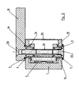
- the gripping mechanism has a housing (1) with two coaxial cavities (2a, 2b).
- a piston-rod unit (3) is housed as an actuating unit and sealed with the lid (11a).
- the gear unit consisting of at least one slider-crank mechanism or at least one gear-rack unit or a worm-worm wheel unit housed.
- the piston rod drives by means of slide (4a) and coupling member (5) to the central part of the three-piece designed drive shaft (6) as a crankshaft.
- the torque is transmitted from the middle part of the drive shaft (6), the crank, on the frontal toothing by means of holes and pins (8) on the gripper fingers (10).
- the middle part of the drive shaft (6) has on both sides two flat surfaces with the holes for the pins (8) and can thus be introduced through the one-sided opening of the gripper housing in the gear housing (2b). Parts of these flat surfaces can serve as thrust bearings of the drive shaft (6).
- the gear chamber (2b) may also be a simple bore in which a toothed shaft is located as a drive shaft (6) which is driven by a toothed piston rod.
- the drive shaft (6) consists of three parts (6a, 6b, 6c) and has a support-support-bearing of the X-arrangement.
- the middle part of the drive shaft, the crank (6a), on both sides has two surfaces (7a, 7b), which serve as thrust bearing surfaces of the support-support bearing.
- In the middle of these bearing surfaces are on both sides bores, which receive the neck bearing (6b) of the gripper finger and the abutment (6c) by means of pins (8) center and on these pins or by means of another type of toothing the torque of the drive shaft (6) on the Transfer gripper fingers (10).
- the radial bearing of the drive shaft (6) in the gripper housing (1) is mounted on the one hand as a neck bearing (6b) on the gripper finger (10) and on the other hand on a separate abutment (6c).
- the pre-assembled Gear consisting of the slide (4a), coupling (5) and cranks (6a), through the front opening in the gripper housing (1) insert and fasten with the piston rod of the actuator unit (3).
- the gear chamber (2b) is then sealed with the lid (11 b) and closed.
- the drive shaft (6) After insertion of the gripper finger (10) with the Axialdichtring (9) and located on the gripper finger (10) neck bearing (6b) from one side and the abutment (6c) with the Axialdichtring (9) from the other side and its axial attachment by means of screws (12a, 12b) through the hollow center, the drive shaft (6) is completely assembled along with their storage.
- the support-support-bearing of the drive shaft can also be realized in O arrangement. In this case, the thrust bearing surfaces on the neck of the gripper finger (10) and the abutment (6c) outside the housing within the Axialdichtringe (9).
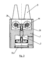
- the gripper fingers (10) are each driven by a two- or three-piece toothed drive shaft (6d), a gear shaft.
- a slide rack (4b) which drives the toothed drive shaft (6d) and with it the gripper finger (10).
- the rack (4b) and the toothed drive shaft (6d) can also be replaced by a worm and a worm wheel in order to realize a rotary drive, for example by an electric motor.
- the toothed drive shaft (6d) is mounted axially and radially in the gripper housing (1), wherein the neck bearing (6b) forms part of the gripper finger (10) on this and the abutment (6c) separately on the opposite side Gripper finger is located.
- the toothed central part is located either on the neck bearing (6b) or on the abutment (6c).
- the division of the toothed drive shaft can also be done within the toothed region in a straight toothing, so that the toothing is composed of two halves, which are pinned together axially or otherwise secured.
- the gear chamber (2b) consists exclusively of holes for the toothed rod of the drive unit (3) and the drive shafts (6).
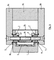
- the gripper finger consists of two halves (10a, 10b), which are arranged on both sides of the housing and outside of the housing area by means of the jaw carrier (10c) are releasably secured together.
- Each gripper finger half (10a, 10b) includes a neck bearing (6b) of the drive shaft, crankshaft or gear shaft, an axial seal (9), and in O-arrangement also a thrust bearing surface of the support-support bearing.
- the middle part (6a) of the drive shaft together with the finger parts (10a, 10b) and the jaw carrier (10c) forms a closed, bending and torsion-resistant unit.
- the gripper finger halves (10a, 10b) support and center with the aid of their integrated neck bearing (6b) and their pins (8) or axial toothing the central part (6a) of the drive shaft and form with its thrust bearing surfaces (7) and the jaw carrier (10c) a fully closed, bending and torsion-resistant gripper finger, which is relative to its drive shaft, crank or gear shaft, in the context of the pitch of the pins (8) adjustable in angle.
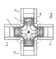
- a plurality of gripping fingers (10) can be arranged around the central actuating unit (3) and all driven pneumatically, hydraulically or electromotively synchronously by means of a single centrally arranged slide (4c) and a crank or gear shaft.
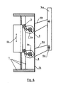
- Fig. 6 drive two multi-part designed drive shafts (6), designed here as crankshafts, depending on a handlebar (10d), at the ends of a gripper finger (14a) is articulated. While a handlebar is connected by a rotary joint with the gripper finger, the second link engages with its bearing pin in a slot (13a) of the gripper finger (14a).
- the links (10d) may be of different lengths or the cranks (6a) may perform different angles of rotation to provide additional rotation to the gripper finger (14a) during the opening or closing operation.
- the web shape of the link (13a) can also be the gripper finger an additional movement are made possible, and that each gripper finger a different movement when the handling task requires it.
- the link (13a) can also be attached to one of the two links (10d), so that the gripper finger (14a) has only two pivot joints.
- the two links (10d) can be dispensed with the scenery on the gripper fingers (14a) or the handlebar (10d).
- at Abandonment of the slide (13a) can also be dispensed with the external drive of one of the two links (10d), as long as the resulting four-bar linkage (1, 10d, 14a, 10d) does not come in its covering or stretched position.
- the gripper finger (14a), which is driven by two arms (10d) can also move clearly and securely in its stretch or cover position with the handlebars (10d), thereby transmitting forces and moments to the gripping object.
- the linear actuator (4d) can be driven pneumatically, hydraulically or by electric motor. It drives the cranks (6a) of the drive shafts (6) via the coupling links (5) and can be disassembled in two separate drives in tandem or coaxial arrangement and positively, frictionally or coupled together to the two links (10d ) partly together and partly separately from each other to drive.
- the lid (11c) hermetically seals off the gear compartment so that the entire gripping mechanism is completely sealed.
- the linearly driven slide (4e) with its rack (4b) sets two multi-part designed and toothed drive shafts (6d) in rotational movement.
- the radial bearings of the toothed drive shafts (6d) are mounted as a neck bearing (6b) on the links (10d, 10e) and connected by means of holes and pins (8) with the toothed part of the drive shaft, adjustable in angle.
- the handlebar (10d) engages with its end pivotally on the gripper finger (14b).
- the link (10e) has at its end a link (13b), in which engages the bearing pin of the gripper finger (14b).
- the gate (13b) can be replaced by a binary link consisting of a small link with a swivel joint on both sides, not shown. Kinematically, this gripping mechanism behaves similar to that in the FIG. 6 has been described. On the drive of the second drive shaft can be omitted here under the same conditions, as in the FIG. 6 described.
- the drive of the second drive shaft can also be effected by a toothed belt or a chain via the first drive shaft.
Landscapes
- Engineering & Computer Science (AREA)
- Robotics (AREA)
- Mechanical Engineering (AREA)
- Manipulator (AREA)
- Load-Engaging Elements For Cranes (AREA)
- Jigs For Machine Tools (AREA)
Applications Claiming Priority (2)
| Application Number | Priority Date | Filing Date | Title |
|---|---|---|---|
| DE102007039399A DE102007039399B4 (de) | 2007-08-21 | 2007-08-21 | Greifmechanismus mit dreiteiliger Getriebewelle |
| PCT/DE2008/001365 WO2009024138A2 (de) | 2007-08-21 | 2008-08-19 | Greifmechanismus mit geteilter antriebswelle für einen greiferfinger |
Publications (2)
| Publication Number | Publication Date |
|---|---|
| EP2190633A2 EP2190633A2 (de) | 2010-06-02 |
| EP2190633B1 true EP2190633B1 (de) | 2011-07-13 |
Family
ID=40254764
Family Applications (1)
| Application Number | Title | Priority Date | Filing Date |
|---|---|---|---|
| EP08801188A Active EP2190633B1 (de) | 2007-08-21 | 2008-08-19 | Greifmechanismus mit geteilter antriebswelle für einen greiferfinger |
Country Status (6)
| Country | Link |
|---|---|
| US (1) | US8235438B2 (OSRAM) |
| EP (1) | EP2190633B1 (OSRAM) |
| JP (1) | JP5603772B2 (OSRAM) |
| AT (1) | ATE516118T1 (OSRAM) |
| DE (2) | DE102007039399B4 (OSRAM) |
| WO (1) | WO2009024138A2 (OSRAM) |
Cited By (1)
| Publication number | Priority date | Publication date | Assignee | Title |
|---|---|---|---|---|
| CN106182063A (zh) * | 2016-08-15 | 2016-12-07 | 广东技术师范学院 | 一种用于流水线上10kg重棒料搬运的机械人手爪 |
Families Citing this family (13)
| Publication number | Priority date | Publication date | Assignee | Title |
|---|---|---|---|---|
| KR101101062B1 (ko) * | 2010-08-19 | 2011-12-30 | 삼성에스디아이 주식회사 | 충방전 장치 |
| CN102717378B (zh) * | 2012-02-01 | 2015-05-20 | 昆山华恒焊接股份有限公司 | 机械手装置 |
| CN103878777B (zh) * | 2014-03-17 | 2016-02-24 | 青岛赶海机器人有限公司 | 一种空间紧凑夹紧力大长行程的工业机器人抓手 |
| US9486925B1 (en) * | 2016-02-22 | 2016-11-08 | Jeffrey A. Stroop | Mechanical arm |
| CN106393152A (zh) * | 2016-12-01 | 2017-02-15 | 无锡市创恒机械有限公司 | 同步机械爪 |
| CN107186746B (zh) * | 2017-06-30 | 2024-01-09 | 江苏钜普汽车零部件有限公司 | 一种机械臂 |
| CN110253608B (zh) * | 2019-07-23 | 2024-10-25 | 姚振 | 一种新型抓取握紧式机械手 |
| CN110978020A (zh) * | 2019-12-13 | 2020-04-10 | 中国科学院深圳先进技术研究院 | 机械手及其自动定心夹紧夹具 |
| CN111674915A (zh) * | 2020-06-28 | 2020-09-18 | 岳阳经济技术开发区弘发物流有限公司 | 一种物流周转箱的抓取装置 |
| CN113682805B (zh) * | 2021-09-01 | 2022-11-18 | 沈阳工业大学 | 抓取机构及转运装置 |
| CN113858252B (zh) * | 2021-10-08 | 2023-01-17 | 滕州市智星电力电子工程有限公司 | 一种变电站维修用机器人配件抓取装置 |
| WO2023072430A1 (en) * | 2021-10-27 | 2023-05-04 | Baker Hughes Energy Technology UK Limited | Methane hydrate production equipment and method |
| CN116329456B (zh) * | 2023-04-06 | 2024-03-15 | 东莞辉科机器人自动化股份有限公司 | 摆臂锻压机械手 |
Family Cites Families (28)
| Publication number | Priority date | Publication date | Assignee | Title |
|---|---|---|---|---|
| DE316522C (OSRAM) | ||||
| JPS5117645Y2 (OSRAM) * | 1971-05-06 | 1976-05-12 | ||
| JPS5125348Y2 (OSRAM) * | 1972-09-04 | 1976-06-28 | ||
| JPS5811505Y2 (ja) * | 1978-10-27 | 1983-03-04 | 株式会社昌運工作所 | ロ−ダの把握装置 |
| JPS6031986B2 (ja) * | 1981-03-06 | 1985-07-25 | 株式会社 坂戸工作所 | 掴み装置 |
| JPS584385A (ja) * | 1981-06-29 | 1983-01-11 | 三菱重工業株式会社 | マニピユレ−タ用ハンド |
| JPS5993285A (ja) * | 1982-11-15 | 1984-05-29 | 豊田工機株式会社 | 交換式ハンドを備えた作業装置 |
| JPS59107887A (ja) * | 1982-12-08 | 1984-06-22 | 広瀬 茂男 | 柔軟把握機構 |
| US4598942A (en) * | 1984-07-23 | 1986-07-08 | Westinghouse Electric Corp. | Force-controlled gripper with adaptive accommodation |
| SU1337251A1 (ru) | 1985-01-07 | 1987-09-15 | Экспериментальный научно-исследовательский институт металлорежущих станков | Захватное устройство |
| JPH0418795Y2 (OSRAM) * | 1985-04-25 | 1992-04-27 | ||
| DE3623586A1 (de) * | 1986-07-12 | 1988-01-28 | Heller Geb Gmbh Maschf | Greifvorrichtung |
| US4728137A (en) * | 1986-07-22 | 1988-03-01 | American Engineering And Trade, Inc. | Compound toggle robotic gripper |
| DE8800888U1 (de) | 1988-01-26 | 1988-03-10 | Prämeta Präzisionsmetall- und Kunststofferzeugnisse G. Baumann & Co, 5000 Köln | Handhabungsgerät zum Transportieren und Positionieren von Gegenständen |
| JPH03131489A (ja) * | 1989-10-16 | 1991-06-05 | Fujitsu Ltd | 2指ハンド |
| JP2807006B2 (ja) | 1989-12-21 | 1998-09-30 | 中部電力株式会社 | 電線切断・接続装置 |
| DE4014002A1 (de) | 1990-04-27 | 1991-10-31 | Noell Gmbh | Roboter und robotgreifer |
| US5072652A (en) * | 1990-11-16 | 1991-12-17 | Blatt John A | Gripping device having impact cushioning means |
| JP2531910Y2 (ja) * | 1992-03-31 | 1997-04-09 | 株式会社スガイ | 物品把持装置 |
| JPH0866888A (ja) * | 1994-08-29 | 1996-03-12 | Japan Servo Co Ltd | ロボットハンドのフィンガ駆動機構 |
| JP3749315B2 (ja) * | 1996-09-06 | 2006-02-22 | Smc株式会社 | チャック装置 |
| US5884952A (en) * | 1997-06-02 | 1999-03-23 | Rubberline Products Ltd | Gripper device |
| US6244644B1 (en) * | 1999-01-25 | 2001-06-12 | The United States Of America As Represented By The Administrator Of The National Aeronautics And Space Administration | Compact dexterous robotic hand |
| DE20021296U1 (de) * | 2000-12-15 | 2001-05-23 | Morawski, Boleslaw, 58515 Lüdenscheid | Handhabungsgerät |
| JP3906445B2 (ja) * | 2003-01-10 | 2007-04-18 | Smc株式会社 | 電動チャック装置 |
| ITBS20030077A1 (it) * | 2003-08-29 | 2005-02-28 | Gimatic Spa | Pinza pneumatica angolare. |
| DE102004056229A1 (de) * | 2004-11-22 | 2006-05-24 | Günter Neumann GmbH | Kraftspanner |
| JP4614878B2 (ja) * | 2005-12-28 | 2011-01-19 | 株式会社ハーモニック・ドライブ・システムズ | ロボットハンドの指ユニットおよび組立方法 |
-
2007
- 2007-08-21 DE DE102007039399A patent/DE102007039399B4/de not_active Expired - Fee Related
-
2008
- 2008-08-19 US US12/531,285 patent/US8235438B2/en active Active
- 2008-08-19 JP JP2010521299A patent/JP5603772B2/ja active Active
- 2008-08-19 DE DE112008002849T patent/DE112008002849A5/de not_active Withdrawn
- 2008-08-19 WO PCT/DE2008/001365 patent/WO2009024138A2/de not_active Ceased
- 2008-08-19 EP EP08801188A patent/EP2190633B1/de active Active
- 2008-08-19 AT AT08801188T patent/ATE516118T1/de active
Cited By (1)
| Publication number | Priority date | Publication date | Assignee | Title |
|---|---|---|---|---|
| CN106182063A (zh) * | 2016-08-15 | 2016-12-07 | 广东技术师范学院 | 一种用于流水线上10kg重棒料搬运的机械人手爪 |
Also Published As
| Publication number | Publication date |
|---|---|
| ATE516118T1 (de) | 2011-07-15 |
| DE102007039399B4 (de) | 2010-05-12 |
| WO2009024138A8 (de) | 2010-04-29 |
| US20100096870A1 (en) | 2010-04-22 |
| JP2010536589A (ja) | 2010-12-02 |
| JP5603772B2 (ja) | 2014-10-08 |
| DE102007039399A1 (de) | 2009-02-26 |
| WO2009024138A3 (de) | 2009-04-30 |
| WO2009024138A2 (de) | 2009-02-26 |
| DE112008002849A5 (de) | 2010-11-25 |
| US8235438B2 (en) | 2012-08-07 |
| EP2190633A2 (de) | 2010-06-02 |
Similar Documents
| Publication | Publication Date | Title |
|---|---|---|
| EP2190633B1 (de) | Greifmechanismus mit geteilter antriebswelle für einen greiferfinger | |
| DE102014009893B4 (de) | Endeffektor für ein Instrument | |
| DE102016004787B4 (de) | Antriebsvorrichtung für einen Roboter und Verfahren zu ihrer Herstellung | |
| EP0584144B1 (de) | Greifermechanismus | |
| EP2190632B1 (de) | Greifmechanismus mit zwei antriebswellen pro greiferfinger | |
| DE1148721B (de) | Ferngesteuerter Manipulator | |
| EP1277533A1 (de) | Spannvorrichtung für die rotatorische Bearbeitung von Werkstücken | |
| DE102014009891A1 (de) | Instrument | |
| EP0288660A2 (de) | Werkzeugspindelanordnung mit einem elektrischen Antriebsmotor | |
| EP3245424A1 (de) | Getriebe, elektrische antriebsvorrichtung und industrieroboter | |
| DE102014009892B4 (de) | Antriebseinheit mit magnetischer Schnittstelle | |
| DE2454743C2 (de) | Einwickelvorrichtung für Bonbons oder dgl. | |
| DE102006005580B4 (de) | Linearbewegungs- und Drehstellglied | |
| DE102008009869A1 (de) | Kurbelwelle, insbesondere für eine Brennkraftmaschine | |
| EP3468009B1 (de) | Rotations-hub-modul zum rotativen und/oder linearen bewegen eines arbeitselements | |
| DE102013017244A1 (de) | Getriebe zum Übertragen einer Drehbewegung und Antriebsmodul mit einem solchen Getriebe | |
| DE1925645A1 (de) | Betaetigungsvorrichtung fuer Greiforgane | |
| EP2322325A2 (de) | Werkzeugadapter | |
| DE3207519A1 (de) | Kupplungseinrichtung | |
| DE3911073C1 (OSRAM) | ||
| EP4038293B1 (de) | Eine hochdruckregelarmatur für eine hochdruckanlage mit einer vorrichtung zum betätigen eines ventils | |
| DE4238101A1 (de) | Modulares Greifersystem | |
| DE102016216749A1 (de) | Werkzeugwechselgetriebe | |
| EP0650432B1 (de) | Vorrichtung zur änderung der pedalarmlänge | |
| DE2254329C2 (de) | Drehschraubereinheit zum gleichzeitigen Anziehen von mindestens zwei Schrauben |
Legal Events
| Date | Code | Title | Description |
|---|---|---|---|
| PUAI | Public reference made under article 153(3) epc to a published international application that has entered the european phase |
Free format text: ORIGINAL CODE: 0009012 |
|
| 17P | Request for examination filed |
Effective date: 20100201 |
|
| AK | Designated contracting states |
Kind code of ref document: A2 Designated state(s): AT BE BG CH CY CZ DE DK EE ES FI FR GB GR HR HU IE IS IT LI LT LU LV MC MT NL NO PL PT RO SE SI SK TR |
|
| AX | Request for extension of the european patent |
Extension state: AL BA MK RS |
|
| GRAP | Despatch of communication of intention to grant a patent |
Free format text: ORIGINAL CODE: EPIDOSNIGR1 |
|
| GRAS | Grant fee paid |
Free format text: ORIGINAL CODE: EPIDOSNIGR3 |
|
| GRAA | (expected) grant |
Free format text: ORIGINAL CODE: 0009210 |
|
| DAX | Request for extension of the european patent (deleted) | ||
| AK | Designated contracting states |
Kind code of ref document: B1 Designated state(s): AT BE BG CH CY CZ DE DK EE ES FI FR GB GR HR HU IE IS IT LI LT LU LV MC MT NL NO PL PT RO SE SI SK TR |
|
| REG | Reference to a national code |
Ref country code: GB Ref legal event code: FG4D Free format text: NOT ENGLISH |
|
| REG | Reference to a national code |
Ref country code: CH Ref legal event code: EP |
|
| REG | Reference to a national code |
Ref country code: IE Ref legal event code: FG4D Free format text: LANGUAGE OF EP DOCUMENT: GERMAN |
|
| REG | Reference to a national code |
Ref country code: DE Ref legal event code: R096 Ref document number: 502008004205 Country of ref document: DE Effective date: 20110908 |
|
| REG | Reference to a national code |
Ref country code: NL Ref legal event code: VDEP Effective date: 20110713 |
|
| PG25 | Lapsed in a contracting state [announced via postgrant information from national office to epo] |
Ref country code: MT Free format text: LAPSE BECAUSE OF FAILURE TO SUBMIT A TRANSLATION OF THE DESCRIPTION OR TO PAY THE FEE WITHIN THE PRESCRIBED TIME-LIMIT Effective date: 20110713 |
|
| PG25 | Lapsed in a contracting state [announced via postgrant information from national office to epo] |
Ref country code: SE Free format text: LAPSE BECAUSE OF FAILURE TO SUBMIT A TRANSLATION OF THE DESCRIPTION OR TO PAY THE FEE WITHIN THE PRESCRIBED TIME-LIMIT Effective date: 20110713 Ref country code: IS Free format text: LAPSE BECAUSE OF FAILURE TO SUBMIT A TRANSLATION OF THE DESCRIPTION OR TO PAY THE FEE WITHIN THE PRESCRIBED TIME-LIMIT Effective date: 20111113 Ref country code: LT Free format text: LAPSE BECAUSE OF FAILURE TO SUBMIT A TRANSLATION OF THE DESCRIPTION OR TO PAY THE FEE WITHIN THE PRESCRIBED TIME-LIMIT Effective date: 20110713 Ref country code: NO Free format text: LAPSE BECAUSE OF FAILURE TO SUBMIT A TRANSLATION OF THE DESCRIPTION OR TO PAY THE FEE WITHIN THE PRESCRIBED TIME-LIMIT Effective date: 20111013 Ref country code: PT Free format text: LAPSE BECAUSE OF FAILURE TO SUBMIT A TRANSLATION OF THE DESCRIPTION OR TO PAY THE FEE WITHIN THE PRESCRIBED TIME-LIMIT Effective date: 20111114 Ref country code: NL Free format text: LAPSE BECAUSE OF FAILURE TO SUBMIT A TRANSLATION OF THE DESCRIPTION OR TO PAY THE FEE WITHIN THE PRESCRIBED TIME-LIMIT Effective date: 20110713 Ref country code: FI Free format text: LAPSE BECAUSE OF FAILURE TO SUBMIT A TRANSLATION OF THE DESCRIPTION OR TO PAY THE FEE WITHIN THE PRESCRIBED TIME-LIMIT Effective date: 20110713 Ref country code: HR Free format text: LAPSE BECAUSE OF FAILURE TO SUBMIT A TRANSLATION OF THE DESCRIPTION OR TO PAY THE FEE WITHIN THE PRESCRIBED TIME-LIMIT Effective date: 20110713 |
|
| REG | Reference to a national code |
Ref country code: IE Ref legal event code: FD4D |
|
| BERE | Be: lapsed |
Owner name: SAADAT M. MOHSEN Effective date: 20110831 |
|
| PG25 | Lapsed in a contracting state [announced via postgrant information from national office to epo] |
Ref country code: PL Free format text: LAPSE BECAUSE OF FAILURE TO SUBMIT A TRANSLATION OF THE DESCRIPTION OR TO PAY THE FEE WITHIN THE PRESCRIBED TIME-LIMIT Effective date: 20110713 Ref country code: SI Free format text: LAPSE BECAUSE OF FAILURE TO SUBMIT A TRANSLATION OF THE DESCRIPTION OR TO PAY THE FEE WITHIN THE PRESCRIBED TIME-LIMIT Effective date: 20110713 Ref country code: GR Free format text: LAPSE BECAUSE OF FAILURE TO SUBMIT A TRANSLATION OF THE DESCRIPTION OR TO PAY THE FEE WITHIN THE PRESCRIBED TIME-LIMIT Effective date: 20111014 Ref country code: LV Free format text: LAPSE BECAUSE OF FAILURE TO SUBMIT A TRANSLATION OF THE DESCRIPTION OR TO PAY THE FEE WITHIN THE PRESCRIBED TIME-LIMIT Effective date: 20110713 Ref country code: CY Free format text: LAPSE BECAUSE OF FAILURE TO SUBMIT A TRANSLATION OF THE DESCRIPTION OR TO PAY THE FEE WITHIN THE PRESCRIBED TIME-LIMIT Effective date: 20110713 |
|
| PG25 | Lapsed in a contracting state [announced via postgrant information from national office to epo] |
Ref country code: MC Free format text: LAPSE BECAUSE OF NON-PAYMENT OF DUE FEES Effective date: 20110831 |
|
| PG25 | Lapsed in a contracting state [announced via postgrant information from national office to epo] |
Ref country code: CZ Free format text: LAPSE BECAUSE OF FAILURE TO SUBMIT A TRANSLATION OF THE DESCRIPTION OR TO PAY THE FEE WITHIN THE PRESCRIBED TIME-LIMIT Effective date: 20110713 Ref country code: IE Free format text: LAPSE BECAUSE OF FAILURE TO SUBMIT A TRANSLATION OF THE DESCRIPTION OR TO PAY THE FEE WITHIN THE PRESCRIBED TIME-LIMIT Effective date: 20110713 Ref country code: SK Free format text: LAPSE BECAUSE OF FAILURE TO SUBMIT A TRANSLATION OF THE DESCRIPTION OR TO PAY THE FEE WITHIN THE PRESCRIBED TIME-LIMIT Effective date: 20110713 |
|
| PLBE | No opposition filed within time limit |
Free format text: ORIGINAL CODE: 0009261 |
|
| REG | Reference to a national code |
Ref country code: FR Ref legal event code: ST Effective date: 20120430 |
|
| STAA | Information on the status of an ep patent application or granted ep patent |
Free format text: STATUS: NO OPPOSITION FILED WITHIN TIME LIMIT |
|
| PG25 | Lapsed in a contracting state [announced via postgrant information from national office to epo] |
Ref country code: BE Free format text: LAPSE BECAUSE OF NON-PAYMENT OF DUE FEES Effective date: 20110831 Ref country code: IT Free format text: LAPSE BECAUSE OF FAILURE TO SUBMIT A TRANSLATION OF THE DESCRIPTION OR TO PAY THE FEE WITHIN THE PRESCRIBED TIME-LIMIT Effective date: 20110713 Ref country code: RO Free format text: LAPSE BECAUSE OF FAILURE TO SUBMIT A TRANSLATION OF THE DESCRIPTION OR TO PAY THE FEE WITHIN THE PRESCRIBED TIME-LIMIT Effective date: 20110713 Ref country code: EE Free format text: LAPSE BECAUSE OF FAILURE TO SUBMIT A TRANSLATION OF THE DESCRIPTION OR TO PAY THE FEE WITHIN THE PRESCRIBED TIME-LIMIT Effective date: 20110713 |
|
| 26N | No opposition filed |
Effective date: 20120416 |
|
| PG25 | Lapsed in a contracting state [announced via postgrant information from national office to epo] |
Ref country code: DK Free format text: LAPSE BECAUSE OF FAILURE TO SUBMIT A TRANSLATION OF THE DESCRIPTION OR TO PAY THE FEE WITHIN THE PRESCRIBED TIME-LIMIT Effective date: 20110713 |
|
| REG | Reference to a national code |
Ref country code: DE Ref legal event code: R097 Ref document number: 502008004205 Country of ref document: DE Effective date: 20120416 |
|
| PG25 | Lapsed in a contracting state [announced via postgrant information from national office to epo] |
Ref country code: FR Free format text: LAPSE BECAUSE OF NON-PAYMENT OF DUE FEES Effective date: 20110913 |
|
| REG | Reference to a national code |
Ref country code: CH Ref legal event code: PL |
|
| GBPC | Gb: european patent ceased through non-payment of renewal fee |
Effective date: 20120819 |
|
| PG25 | Lapsed in a contracting state [announced via postgrant information from national office to epo] |
Ref country code: CH Free format text: LAPSE BECAUSE OF NON-PAYMENT OF DUE FEES Effective date: 20120831 Ref country code: LI Free format text: LAPSE BECAUSE OF NON-PAYMENT OF DUE FEES Effective date: 20120831 Ref country code: ES Free format text: LAPSE BECAUSE OF FAILURE TO SUBMIT A TRANSLATION OF THE DESCRIPTION OR TO PAY THE FEE WITHIN THE PRESCRIBED TIME-LIMIT Effective date: 20111024 |
|
| PG25 | Lapsed in a contracting state [announced via postgrant information from national office to epo] |
Ref country code: LU Free format text: LAPSE BECAUSE OF NON-PAYMENT OF DUE FEES Effective date: 20110819 |
|
| PG25 | Lapsed in a contracting state [announced via postgrant information from national office to epo] |
Ref country code: BG Free format text: LAPSE BECAUSE OF FAILURE TO SUBMIT A TRANSLATION OF THE DESCRIPTION OR TO PAY THE FEE WITHIN THE PRESCRIBED TIME-LIMIT Effective date: 20111013 |
|
| PG25 | Lapsed in a contracting state [announced via postgrant information from national office to epo] |
Ref country code: GB Free format text: LAPSE BECAUSE OF NON-PAYMENT OF DUE FEES Effective date: 20120819 |
|
| PG25 | Lapsed in a contracting state [announced via postgrant information from national office to epo] |
Ref country code: TR Free format text: LAPSE BECAUSE OF FAILURE TO SUBMIT A TRANSLATION OF THE DESCRIPTION OR TO PAY THE FEE WITHIN THE PRESCRIBED TIME-LIMIT Effective date: 20110713 |
|
| PG25 | Lapsed in a contracting state [announced via postgrant information from national office to epo] |
Ref country code: HU Free format text: LAPSE BECAUSE OF FAILURE TO SUBMIT A TRANSLATION OF THE DESCRIPTION OR TO PAY THE FEE WITHIN THE PRESCRIBED TIME-LIMIT Effective date: 20110713 |
|
| REG | Reference to a national code |
Ref country code: AT Ref legal event code: MM01 Ref document number: 516118 Country of ref document: AT Kind code of ref document: T Effective date: 20130819 |
|
| PG25 | Lapsed in a contracting state [announced via postgrant information from national office to epo] |
Ref country code: AT Free format text: LAPSE BECAUSE OF NON-PAYMENT OF DUE FEES Effective date: 20130819 |
|
| PGFP | Annual fee paid to national office [announced via postgrant information from national office to epo] |
Ref country code: DE Payment date: 20250722 Year of fee payment: 18 |