EP2188822B1 - Hochspannungsleistungsschalter mit einem schalter zum zuschalten eines einschaltwiderstandes - Google Patents
Hochspannungsleistungsschalter mit einem schalter zum zuschalten eines einschaltwiderstandes Download PDFInfo
- Publication number
- EP2188822B1 EP2188822B1 EP08803715.5A EP08803715A EP2188822B1 EP 2188822 B1 EP2188822 B1 EP 2188822B1 EP 08803715 A EP08803715 A EP 08803715A EP 2188822 B1 EP2188822 B1 EP 2188822B1
- Authority
- EP
- European Patent Office
- Prior art keywords
- contact
- circuit breaker
- voltage circuit
- switch
- switching contact
- Prior art date
- Legal status (The legal status is an assumption and is not a legal conclusion. Google has not performed a legal analysis and makes no representation as to the accuracy of the status listed.)
- Active
Links
Images




Classifications
-
- H—ELECTRICITY
- H01—ELECTRIC ELEMENTS
- H01H—ELECTRIC SWITCHES; RELAYS; SELECTORS; EMERGENCY PROTECTIVE DEVICES
- H01H33/00—High-tension or heavy-current switches with arc-extinguishing or arc-preventing means
- H01H33/02—Details
- H01H33/04—Means for extinguishing or preventing arc between current-carrying parts
- H01H33/16—Impedances connected with contacts
-
- H—ELECTRICITY
- H01—ELECTRIC ELEMENTS
- H01H—ELECTRIC SWITCHES; RELAYS; SELECTORS; EMERGENCY PROTECTIVE DEVICES
- H01H33/00—High-tension or heavy-current switches with arc-extinguishing or arc-preventing means
- H01H33/60—Switches wherein the means for extinguishing or preventing the arc do not include separate means for obtaining or increasing flow of arc-extinguishing fluid
- H01H33/66—Vacuum switches
- H01H33/664—Contacts; Arc-extinguishing means, e.g. arcing rings
-
- H—ELECTRICITY
- H01—ELECTRIC ELEMENTS
- H01H—ELECTRIC SWITCHES; RELAYS; SELECTORS; EMERGENCY PROTECTIVE DEVICES
- H01H33/00—High-tension or heavy-current switches with arc-extinguishing or arc-preventing means
- H01H33/60—Switches wherein the means for extinguishing or preventing the arc do not include separate means for obtaining or increasing flow of arc-extinguishing fluid
- H01H33/66—Vacuum switches
- H01H33/666—Operating arrangements
-
- H—ELECTRICITY
- H02—GENERATION; CONVERSION OR DISTRIBUTION OF ELECTRIC POWER
- H02B—BOARDS, SUBSTATIONS OR SWITCHING ARRANGEMENTS FOR THE SUPPLY OR DISTRIBUTION OF ELECTRIC POWER
- H02B13/00—Arrangement of switchgear in which switches are enclosed in, or structurally associated with, a casing, e.g. cubicle
- H02B13/02—Arrangement of switchgear in which switches are enclosed in, or structurally associated with, a casing, e.g. cubicle with metal casing
- H02B13/035—Gas-insulated switchgear
- H02B13/0352—Gas-insulated switchgear for three phase switchgear
Definitions
- the invention relates to a high-voltage circuit breaker according to the preamble of claim 1.
- Such a high-voltage circuit breaker is disclosed in the publication US 4,499,350 known.
- This known high-voltage circuit breaker has a main current path, which is separable by means of an interrupter unit. Parallel to the main current path, a secondary current path is guided, in which a switch and an on-resistance are connected in series.
- the on-resistance is turned on shortly before the closing of the contact arrangement of the interrupter unit in the circuit, such that the current flows shortly before the closing of the main current path through the secondary current path with the on-resistance. Consequently, the insertion of the on-resistance into the circuit occurs under load.
- a movable breaker contact of the breaker unit is driven by levers and angle elements of a drive unit.
- a powered contact of the switch is driven by the same drive unit.
- the driven contact of the switch cooperates with a likewise movable mating contact of the switch, which is biased by a spring in the direction of the contact.
- the switch closes in front of the breaker unit.
- the interrupter unit closes so that the secondary circuit path is bridged by the main current path.
- opening the High-voltage circuit breaker opens the switch in front of the interrupter unit, so that the interruption of the current takes place by means of the interrupter unit. This is achieved in that the driven contact moves at a greater speed than the mating contact, on which the force of the spring acts.
- a disadvantage of the known high-voltage circuit breaker proves that a complex, consisting of many items mechanics is necessary to operate the interrupter unit and the switch. Furthermore, it proves disadvantageous that when opening the high-voltage circuit breaker, the spring of the switch determines the time at which this opens.
- FIG. 1 Another gas-insulated, encapsulated high-voltage circuit breaker is off US 2 117 975 A known.
- This known high-voltage circuit breaker has an interrupter unit. Parallel to this interrupter unit, a switch and an on-resistance is arranged, wherein the switch is connected in series to the on-resistance. A contact of the switch for switching on the on-resistance is moved along an axis.
- the object of the invention is to provide a gas-insulated high-voltage circuit breaker whose mechanism for opening and closing the interrupter unit and the switch is as simple as possible and reliable.
- the high-voltage power switch has an interrupter unit, an on-resistance and a switch connected in series with the on-resistance.
- the interrupter unit has a movable, driven first break contact, which cooperates to open and close the high voltage circuit breaker with a second breaker contact.
- the switch connected in series with the on-resistance has a movable switching contact whose movement is mechanically coupled by means of a gear to the movement of the first breaker contact.
- the switching contact is designed to be movable so that the switching contact for inserting the on-resistance is rotatable about an axis of rotation.
- the breaker unit on a movable, driven first breaker contact, which acts to open and close the high-voltage circuit breaker with a second breaker contact together.
- the switch has a movable switching contact whose movement is mechanically coupled by means of a transmission to the movement of the first breaker contact.
- the switching contact is rotatably arranged for insertion of the on-resistance about an axis of rotation.
- the mechanical coupling of the switching contact to the switching contact driving movement takes place only during a period of time during the closing of the interrupter unit. This period is shorter than the duration of the movement to close the interrupter unit.
- This type of coupling allows the movement of the switching contact can be optimally selected. Especially This allows almost any control of the times at which the switch closes and reopens during the closure of the interrupter unit.
- the breaker unit on a movable, driven first breaker contact, which acts together to open and close the high-voltage circuit breaker with a second breaker contact.
- the switch has a movable switching contact whose movement is mechanically coupled by means of a transmission to the movement of the first breaker contact.
- the switching contact is rotatably arranged for insertion of the on-resistance about an axis of rotation.
- the transmission is formed by a cam gear, in particular by a link control.
- a cam gear By the cam mechanism or by the gate control a very compact design of the switch is made possible.
- the cam mechanism or the link control that only very few mutually movable elements are needed.
- the switching contact which can be moved at a high speed, can be manufactured from a lightweight material. Consequently, the mechanism for driving the switching contact as well as the first breaker contact can be adapted to the relatively small forces, whereby an overall lightweight construction of the entire mechanism is made possible. Consequently, the drive can also be made smaller.
- the cam mechanism or the link control almost any translation of the linear movement of the first breaker contact in the rotational movement of the breaker contact.
- the cam gear allows almost arbitrary control of the timing at which the switch closes and reopens during the closing of the interrupter unit.
- the gas-insulated, metal-enclosed high-voltage circuit breaker has an interrupter unit, an on-resistance and a switch connected in series with the on-resistance for inserting the on-resistance into the circuit under load.
- the interrupter unit on a movable, driven first breaker contact, which acts together to open and close the high-voltage circuit breaker with a second breaker contact.
- the switch has a movable switching contact whose movement is mechanically coupled by means of a transmission to the movement of the first breaker contact.
- the switching contact is rotatably arranged for insertion of the on-resistance about an axis of rotation.
- the main current path of the high-voltage circuit breaker can be interrupted by means of the interrupter unit.
- the main current path having the interrupter unit is arranged in parallel to a subcurrent path in which the switch and the on-resistance are connected in series with each other. This makes it possible for the on-resistance to be completely disconnected from the circuit after the interrupter unit has been closed, as a result of which no ohmic losses in the on-resistance occur.
- the gas-insulated, metal-enclosed high-voltage circuit breaker has an interrupter unit, an on-resistance and a switch connected in series with the on-resistance for inserting the on-resistance into the circuit under load.
- the interrupter unit has a movable, driven first break contact, which cooperates to open and close the high-voltage circuit breaker with a second breaker contact.
- the switch has a movable switching contact whose movement is mechanically coupled by means of a transmission to the movement of the first breaker contact.
- the switching contact is rotatably arranged for insertion of the on-resistance about an axis of rotation.
- the axis of rotation of the switch contact is perpendicular to the axis. This allows a particularly simple construction of the high-voltage circuit breaker.
- the gas-insulated, metal-enclosed high-voltage circuit breaker has an interrupter unit, an on-resistance and a switch connected in series with the on-resistance for inserting the on-resistance into the circuit under load.
- the interrupter unit on a movable, driven first breaker contact, which acts together to open and close the high-voltage circuit breaker with a second breaker contact.
- the switch has a movable switching contact whose movement is mechanically coupled by means of a transmission to the movement of the first breaker contact.
- the switching contact is rotatably arranged for insertion of the on-resistance about an axis of rotation.
- the slide control is arranged in the same gas space as the switch and / or the interrupter unit. This allows a compact, simple design.
- the gas-insulated, metal-enclosed high-voltage circuit breaker has an interrupter unit, an on-resistance and a switch connected in series with the on-resistance for inserting the on-resistance into the circuit under load.
- the interrupter unit has a movable, driven first break contact, which cooperates to open and close the high-voltage circuit breaker with a second breaker contact.
- the switch has a movable switching contact whose movement is mechanically coupled by means of a transmission to the movement of the first breaker contact.
- the switching contact is rotatably arranged for insertion of the on-resistance about an axis of rotation.
- the switch and the interrupter unit are arranged in a first housing part of the high-voltage circuit breaker and the on-resistance in a second housing part of the high-voltage circuit breaker.
- the axis is a housing axis of the first housing part. This allows the geometry of the first housing part to adapt to the switch and the interrupter unit. Likewise, the geometry of the second housing part can be adapted to the on-resistance. This allows a total of a compact design of the high-voltage circuit breaker.
- the gas-insulated, metal-enclosed high-voltage circuit breaker has an interrupter unit, an on-resistance and a switch connected in series with the on-resistance for inserting the on-resistance into the circuit under load.
- the interrupter unit on a movable, driven first breaker contact, which acts together to open and close the high-voltage circuit breaker with a second breaker contact.
- the switch has a movable switching contact whose movement is mechanically coupled by means of a transmission to the movement of the first breaker contact.
- the switching contact is rotatably arranged for insertion of the on-resistance about an axis of rotation.
- the slide control has two branches.
- the first branch is traversed when closing the interrupter unit and the second branch is when opening the interrupter unit run through. This makes it possible for the switch for connecting the on-resistance to be closed only when the interrupter unit is closed.
- the second branch is designed such that the switch is not closed when opening the interrupter unit.
- the first branch and the second branch define a continuous curved path that is closed.
- the movement of the switching contact is uniquely defined by the link control.
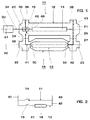
- the two connecting end regions 20, 21 of the first housing part 12 each have an outlet connection 36, by means of which the high-voltage circuit breaker 10 can be connected to other elements of a gas-insulated switchgear.
- the outlet connection pieces 36 are arranged laterally with respect to the first housing axis A1, opposite the connection pieces 24, 25.
- a conductor 40 which is held by known insulating elements (not shown) spaced from the first housing part 12.
- the conductor 40 extends from the opening of the outlet nozzle 36 to the switch 15.
- the conductor 40 is electrically connected to a subsequently described, movable switching contact 46 of the switch 15 and to a movable first breaker contact 32 of the interrupter unit 14.
- a second terminal contact 52 of the on-resistance 18 is connected via a further conductor 42, which passes through the Connecting end portion 23 of the second housing part 16 passes through, connected to a conductor 43 which extends from the connecting piece 25 of the remote from the drive 30 gleichsend Schemes 21 of the first housing part 12 to the outgoing mares 36 of the same connecting end 21.
- a second break contact 33 intended for closing the breaker unit 14 is likewise connected.
- the conductors 40, 41, 42, 43 are held by means of known, disc-shaped or conical insulators within the first and second housing part 12, 16 such that they in the radial direction to the conductor 40, 41, 42, 43 as uniform distances to the first or second housing part 12, 16 have.
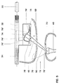
- Fig. 3 shows the switch 15 and parts of the interrupter unit 14 of the first embodiment in detail.
- the first breaker contact 32 movable along the first housing axis A1 is connected directly to the drive rod 34.
- the first breaker contact 32 cooperates to close the breaker unit 14 with the arranged on the first housing axis A1 second breaker contact 33, wherein for closing the first breaker contact 32 is pushed in a known manner to the second breaker contact 33. Consequently, the first breaker contact 32 for closing the breaker unit 14 from the in Fig. 3 shown in the open position of the interrupter unit 14 via a contact position in which the first breaker contact 32 contacts the second breaker contact 33, moved to the closed position in which the first breaker contact 32 is completely pushed onto the second breaker contact 33.
- the first breaker contact 32 moves in the reverse direction.
- the first breaker contact 32 as well as the second breaker contact 33 preferably consists of a rated current contact and a burnup contact (not shown) in a known manner.
- the first interrupter contact 32 is spaced from the second interrupter contact 33 such that even high voltage peaks, such as may occur due to lightning strikes or other disturbances in high voltage networks, not to an arc between the first breaker contact 32 and the second breaker contact 33 leads.
- the switch 15 has a sword-shaped, about a relative to the housing of the high-voltage circuit breaker 10 fixedly mounted rotational axis D movable switching contact 46, which is intended to interact with the fixed counter-contact 48 together.
- the switching contact 46 is substantially elongate and flat. Its length is preferably between 15 cm and 50 cm and more preferably between 25 cm and 40 cm.
- the thickness of the switching contact 46 is preferably between 0.5 mm and 10 mm and more preferably between 2 mm and 4 mm.
- As a material for the switching contact 46 is particularly suitable a light metal such as aluminum.
- the one end region 50 of the switching contact 46 - hereinafter referred to as Mais michsend Scheme 50 - is intended to contact the mating contact 48 to close the switch 15.
- the other end region 52-hereinafter referred to as the actuation end region 52- has two guide surfaces 54, 56 merging into one another, each of which forms a branch 76 ', 76 "of a linkage control 60
- Guide surfaces 54, 56 are intended to cooperate with an actuator 58 of the gate control 60 coupled to the movement of the first break contact 32 of the breaker unit 14.
- a gear 60 is formed, which is also referred to as a cam gear.
- the actuator 58 forms the first gear part and the switching contact 46 cooperating with the first gear part second gear part.
- the transmission of the movement of the actuator 58 is defined on the switching contact 46. Due to the guide surfaces 54, 56, which each form a branch 76 ', 76 "of a motion transmission curve, such a transmission member is also referred to as a backdrop and the transmission as a slide control.
- the axis of rotation D of the switch contact 46 is arranged such that a lever ratio of L1: L2 between 1: 2 to 1: 7 is created, where L1 is the distance from the axis of rotation D to the point of attack of the actuator 58th to the operating end portion 52 and L2 is the distance from the rotation axis D to the free end of the contacting end portion 50.
- the lever ratio L1: L2 is preferably 1: 2.5 to 1: 6 and particularly preferably 1: 2.5 to 1: 4. The lever ratio causes the contacting end portion 50 to be moved at a greater speed determined by the lever ratio L1: 12 than the operating end portion 52.
- the axis of rotation D is at least approximately at right angles to a plane in which at least partially the actuator 58 and the mating contact 48 are located. Next, the flat, movable switch contact 46 also moves in this plane.
- the switching contact 46 is moved by the movement to close the interrupter unit 14 from the in Fig. 3 shown open position (solid line in Fig. 3 ) in the closed position (broken line in Fig. 3 ) emotional.
- a return spring 62 is tensioned, by means of which the switching contact 46 is moved back to the open position at the end of the closing operation of the interrupter unit 14. Consequently, the switch 15 closes and opens during the closing movement of the interrupter unit 14.
- the actuator 58 fixedly coupled to the movement of the first breaker contact 32 moves along the direction of the first housing axis A1. Initially, this movement of the actuator 58 comes into abutment against the first guide surface 54 of the switching contact 46, which is located in the path of movement 64 of the actuator 58 and the first branch 76 'forms. In the further movement of the actuator 58, therefore, the switching contact 46 by the actuator 58 from the in Fig. 3 moved due to the rotational movement of the switching contact 46 - the contact point of the actuator 58 to the first guide surface 54 from the free end of the Betreliistsend Schemes 52 first in the direction of the rotation axis D and then in the reverse direction, to the free end of the Bettechnikistsend Schemes 52 to migrate. During the further closing movement of the first breaker contact 32, the actuator 58 comes out of contact with the switching contact 46. Even before the actuator 58 is out of engagement with the switching contact 46, the breaker unit 14 passes through the contact position.
- the first breaker contact 32 When opening the interrupter unit 14, the first breaker contact 32 is moved from the closed position to the open position. Since the Betjansend Scheme 52 lies in the path of movement 64 of the actuator 58, the actuator 58 abuts when opening the interrupter unit 14 to the second guide surface 56 of the Betjansend Schemes 52, which forms the second branch 76 "of the link control 60. By the actuator 58 is the Actuator end portion 52 is pressed out of the path of movement 64 of actuator 58. As soon as actuator 58 comes into abutment with actuator end portion 52, switch contact 46 returns to the home position due to a return spring 66 cocked during this movement Also, the torque caused by the force of gravity on the switching contact can be utilized for the return spring 62. In particular, the switch 15 remains open during the opening of the interrupter unit 14.
- the actuator 58 is not permanently on the first guide surface 56 and the second guide surface 58 at. Consequently, the switching contact 46 is only temporarily mechanically coupled during the closing of the interrupter unit 14 to the movement of the actuator 58.
- the time span of the coupling of the movement of the switching contact 46 to the movement of the actuator 58 is shorter than the period of time of the closing movement of the interrupter unit 14.
- the switching contact 46 as well as the mating contact 48 of a respective shield 68, 70 (FIG. in Fig. 1 not shown) relative to the first housing part (in FIG.
- the shields 68, 70 are electrically connected to the switching contact 46 and the mating contact 48. Furthermore, it is achieved by the shields 68, 70 that the minimum necessary distance for controlling high voltage differences between the switching contact 46 and mating contact 48 can be reduced.
- the distance from the shield 68 surrounding the switch contact 46 in its open position to the shield 70 surrounding the mating contact 48 is selected such that the breaker unit 14, as well as the switch 15, reliably controls the same maximum voltage, i. that no arcs are formed even in the event of unexpectedly occurring voltage peaks.
- the shield 68 on the side of the switch contact 46 has a slot 72, so that the switch contact 46, which is completely enveloped in the open position by this shield 68, can emerge from this shield 68.
- the temporal movement of the interrupter unit 14 and switch 15 is as follows.
- the switch 15 closes and opens.
- the first interrupter contact 32 moves toward the second interrupter contact 33, thereby reducing the distance between the first and second interrupter contacts 32, 33.
- the contacted Switching contact 46, the mating contact 48 Before it comes to a formation of an arc between the breaker contacts 32, 33, the contacted Switching contact 46, the mating contact 48, so that the Maustrompfad 13 between the conductor 40 and the conductor 43 via the switch 15 and the on-resistance 18 is closed.
- the switch 15 opens so that the auxiliary current path 13 is interrupted and the on-resistance 18 is removed from the circuit.
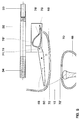
- the switch 15 of a second embodiment of the high voltage circuit breaker is in the Fig. 4-7 shown. Except for the switch 15, the second embodiment is the same as the first embodiment.
- the in the Fig. 4-7 shown parts of the interrupter unit 14 are also formed the same as in the first embodiment.
- the switch 15 in turn has the movable about the rotation axis D, sword-shaped switching contact 46.
- the switching contact 46 has a mandrel 74, which engages in a curved path 76 of a link plate 77.
- the cam track 76 is formed by a groove. The interaction of the mandrel 74 with the curved path 76 forms the slide control 60.
- the two levers L1, L2 are defined on the switch contact 46, wherein the one lever L1 through the mandrel 74 and the rotation axis D and the other lever L2 through the Kunststofftechnischsend Scheme 50 and the axis of rotation D is defined.
- the axis of rotation can also at themaschineticiansend Scheme opposite end portion of the switch contact and the mandrel between the rotation axis and the Kunststofftechniksend Scheme be arranged.
- the link plate 77 is fixedly coupled to the movement of the first breaker contact 32.
- the link plate 77 has the cam track 76, which has a first branch 76 'and a second branch 76 ", wherein the two branches 76', 76" are contiguous and the two end portions of each branch 76 ', 76 "in the other branch 76th ", 76 'go over.
- the first branch 76 ' defines the movement of the switch contact 46 when the interrupter unit 14 closes and the second branch 76 "defines the movement of the switch contact 46 when the interrupter unit 14 is opened.
- the temporal movement of the interrupter unit 14 and the switch 15 is substantially analogous to that of FIG However, the second embodiment allows a better coordination of the movement sequence of the switching contact 46 to the movement of the first breaker contact 32.
- the first branch 76 ' extends from a point 78 (see FIG Fig. 5-7 ) defining a state of the gate control in which the interrupter unit 14 as well as the switch 15 are opened, to a point 78 '. Between the point 78 and the point 78 ', the first branch 76' extends substantially parallel to the direction of movement of the first break contact 32 or only slightly away from the mating contact 48, so that the switching contact 46 passes through this section, at the beginning of the closing movement of the first break contact 32nd , is not substantially moved and thus is not coupled to the movement of the first breaker contact 32.
- first branch 76 is shaped so that switch 15 remains in its closed position for a period of time the interrupter unit 14 passes through the contact position.
- the second branch 76 "between the point 79 and the point 78 is substantially parallel to the line of movement of the first breaker contact 32, so that the switch 15 remains open when opening the breaker unit 14 (see FIG Fig. 7 ) and consequently the switching contact 46 is at least substantially not coupled to the movement of the first breaker contact 32.
- the cam track 76 is formed in the areas in which the two branches 76 ', 76 "together (in the region of the point 78 and the point 79) such that due to the inertia of the switching contact 46 when closing the interrupter unit 14 of the first branch 76th 'and when opening the interrupter unit 14 of the branch 76 "is traversed.
- the switching contact 46 preferably covers an angle range between 30 ° and 80 °, preferably between 35 ° and 70 ° and particularly preferably between 45 ° and 60 °. It can thereby be achieved that the contacting end region 50 moves approximately on a straight line, whereby the risk of the formation of an arc can be minimized, or the requirement for the shield or the geometry of the connecting end region 20 of the first housing part 12 can be simplified.
- a gear 60 is formed similar to the first embodiment, which is also referred to as a cam gear.
- a transmission is also referred to as slide control.
- the link plate 77 forms the first gear part and the switching contact 46 cooperating with the first gear part second gear part.
- the mechanical coupling of the second gear part to the first gear part erflogt by the engagement of the formed on the switching contact 46 mandrel 74 in the cam plate 77 formed on the curved path 76.
- the switching contact 46 and the mating contact 48 are each provided with a shield 68, 70 analogous to the first embodiment.
- FIG. 8 shown third embodiment is largely the same as the second embodiment is formed.
- this shield 68 ' is designed to be movable in this third exemplary embodiment.
- the movable shield 68 ' is coupled either directly to the movement of the first breaker contact 32, directly to the movement of the switch contact 46 or by means of another link control to the movement of the first breaker contact 32.
- a direct coupling can be done for example via a lever joint.
- the further link control is designed substantially analogously to the above-described link control 60, wherein the cam track of the further slide control to select such in that the movement sequence described below of the movable shield is defined by the curved path.
- the movable shield 68 'of the switching contact 46 moves from an initial position (in FIG Fig. 8 indicated by broken lines) toward the mating contact 48 so that initially the contacting end region 50 of the switching contact 46 remains in the shield 68 'as it moves towards the mating contact 48 (see FIG Fig. 8 , shown by solid line).
- the movement of the movable shield 68' is stopped and the Kunststoffssensend Scheme 50 passes through the slot 72 from the movable shield 68 'and then contacted the mating contact 48th
- the minimum distance is determined so that under normal conditions (ie, no unforeseen voltage spikes) no arc is formed between the shields 68 ', 70.
- the switch 15 opens again, this being analogous to the second embodiment. During the opening of the switch 15, the movable shield 68 'is moved back to its original position.
- the burning time of an arc burning between the switching contact 46 and the shielding 70 of the mating contact 48 can be shortened in comparison to the second exemplary embodiment.
Landscapes
- Engineering & Computer Science (AREA)
- Power Engineering (AREA)
- Driving Mechanisms And Operating Circuits Of Arc-Extinguishing High-Tension Switches (AREA)
Description
- Die Erfindung betrifft einen Hochspannungsleistungsschalter gemäss dem Oberbegriff des Anspruchs 1.
- Ein derartiger Hochspannungsleistungsschalter ist aus der Offenlegungsschrift
US 4,499,350 bekannt. Dieser bekannte Hochspannungsleistungsschalter weist einen Hauptstrompfad auf, der mittels einer Unterbrechereinheit trennbar ist. Parallel zum Hauptstrompfad ist ein Nebenstrompfad geführt, in welchem ein Schalter und ein Einschaltwiderstand in Serie zueinander geschaltet sind. Der Einschaltwiderstand wird kurz vor dem Schliessen der Kontaktanordnung der Unterbrechereinheit in den Stromkreis eingeschaltet, derart, dass der Strom kurz vor dem Schliessen des Hauptstrompfades durch den Nebenstrompfad mit dem Einschaltwiderstand fliesst. Folglich erfolgt das Einfügen des Einschaltwiderstandes in den Stromkreis unter Last. Ein beweglicher Unterbrecherkontakt der Unterbrechereinheit ist über Hebel und Winkelelemente von einer Antriebseinheit angetrieben. Ebenso ist ein angetriebener Kontakt des Schalters von derselben Antriebseinheit angetrieben. Der angetriebene Kontakt des Schalters wirkt mit einem ebenfalls beweglichen Gegenkontakt des Schalters zusammen, der mittels einer Feder in Richtung des Kontakts vorgespannt ist. Beim Schliessen des Hochspannungsleistungsschalters schliesst der Schalter vor der Unterbrechereinheit. Nach dem Schliessen des Schalters schliesst die Unterbrechereinheit, sodass der Nebenstrompfad über den Hauptstrompfad überbrückt wird. Beim Öffnen des Hochspannungsleistungsschalters öffnet der Schalter vor der Unterbrechereinheit, sodass die Unterbrechung des Stroms mittels der Unterbrechereinheit erfolgt. Dies wird dadurch erreicht, dass der angetriebene Kontakt sich mit einer grösseren Geschwindigkeit bewegt, als der Gegenkontakt, auf welchen die Kraft der Feder einwirkt. - Nachteilig am bekannten Hochspannungsleistungsschalter erweist sich, dass eine aufwendige, aus vielen Einzelteile bestehende Mechanik nötig ist, um die Unterbrechereinheit und den Schalter zu betätigen. Weiter erweist es sich als nachteilig, dass beim Öffnen des Hochspannungsleistungsschalters die Feder des Schalters den Zeitpunkt bestimmt, zu welchem dieser Öffnet.
- Ein weiterer gasisolierter, gekapselter Hochspannungsleistungsschalter ist aus
US 2 117 975 A bekannt. Dieser bekannte Hochspannungsleistungsschalter weist eine Unterbrechereinheit auf. Parallel zu dieser Unterbrechereinheit ist ein Schalter und ein Einschaltwiderstand angeordnet, wobei der Schalter seriell zum Einschaltwiderstand geschaltet ist. Ein Kontakt des Schalters zum Einschalten des Einschaltwiderstandes wird entlang einer Achse bewegt. - Weitere Hochspannungsschalter sind aus
US 3 538 276 undUS 4 095 069 bekannt. - Aufgabe der Erfindung ist es einen gasisolierten Hochspannungsleistungsschalter zu Schaffen, dessen Mechanik zum Öffnen und Schliessen der Unterbrechereinheit und des Schalters möglichst einfach ausgebildet ist und zuverlässig funktioniert.
- Diese Aufgabe wird durch den Hochspannungsleistungsschalter mit den Merkmalen des Anspruchs 1 gelöst.
- Erfindungsgemäss weist der Hochspannungsleistungsschalter eine Unterbrechereinheit, einen Einschaltwiderstand und einen in Serie zum Einschaltwiderstand geschalteten Schalter auf. Die Unterbrechereinheit weist einen beweglichen, angetriebenen ersten Unterbrecherkontakt auf, der zum Öffnen und Schliessen des Hochspannungsleistungsschalters mit einem zweiten Unterbrecherkontakt zusammen wirkt. Der in Serie zum Einschaltwiderstand geschaltete Schalter weist einen beweglichen Schaltkontakt auf, dessen Bewegung mittels eines Getriebes an die Bewegung des ersten Unterbrecherkontakts mechanisch gekoppelt ist. Der Schaltkontakt ist derart beweglich ausgebildet, dass der Schaltkontakt zum Einfügen des Einschaltwiderstandes um eine Drehachse drehbar ist.
- Gemäss einer bevorzugen Ausführungsform weist der gasisolierte, metallgekapselte Hochspannungsleistungsschalter eine Unterbrechereinheit, einen Einschaltwiderstand und einen in Serie zum Einschaltwiderstand geschalteten Schalter zum Einfügen des Einschaltwiderstandes in den Stromkreis unter Last auf. Dabei weist die Unterbrecher-einheit einen beweglichen, angetriebenen ersten Unterbrecherkontakt auf, der zum Öffnen und Schliessen des Hochspannungsleistungsschalters mit einem zweiten Unterbrecherkontakt zusammen wirkt. Dabei weist der Schalter einen beweglichen Schaltkontakt auf, dessen Bewegung mittels eines Getriebes an die Bewegung des ersten Unterbrecherkontakts mechanisch gekoppelt ist. Der Schaltkontakt ist zum Einfügen des Einschaltwiderstandes um eine Drehachse drehbar angeordnet. Die mechanische Kopplung des Schaltkontaktes an die diesen Schaltkontakt antreibende Bewegung erfolgt lediglich während einer Zeitspanne während des Schliessens der Unterbrechereinheit. Diese Zeitspanne ist kürzer gewählt als die Dauer der Bewegung zum Schliessen der Unterbrechereinheit. Diese Art der Kopplung ermöglicht, dass der Bewegungsablauf des Schaltkontaktes optimal gewählt werden kann. Insbesondere ermöglicht dies eine nahezu beliebige Steuerung der Zeitpunkte, zu welchen der Schalter schliesst und wieder öffnet während des Schliessens der Unterbrechereinheit.
- Gemäss einer bevorzugen Ausführungsform weist der gasisolierte, metallgekapselte Hochspannungsleistungsschalter eine Unterbrechereinheit, einen Einschaltwiderstand und einen in Serie zum Einschaltwiderstand geschalteten Schalter zum Einfügen des Einschaltwiderstandes in den Stromkreis unter Last auf. Dabei weist die Unterbrecher-einheit einen beweglichen, angetriebenen ersten Unterbrecherkontakt auf, der zum Öffnen und Schliessen des Hochspannungsleistungsschalters mit einem zweiten Unterbrecherkontakt zusammen wirkt. Dabei weist der Schalter einen beweglichen Schaltkontakt auf, dessen Bewegung mittels eines Getriebes an die Bewegung des ersten Unterbrecherkontakts mechanisch gekoppelt ist. Der Schaltkontakt ist zum Einfügen des Einschaltwiderstandes um eine Drehachse drehbar angeordnet. Dabei ist das Getriebe durch ein Kurvengetriebe, insbesondere durch eine Kulissensteuerung ausgebildet. Durch das Kurvengetriebe beziehungsweise durch die Kulissensteuerung wird eine sehr kompakte Bauweise des Schalters ermöglicht. Weiter ermöglicht das Kurvengetriebe beziehungsweise die Kulissensteuerung, dass nur sehr wenige, zueinander bewegliche Elemente benötigt werden. Insbesondere kann der mit einer grossen Geschwindigkeit bewegliche Schaltkontakt aus einem leichten Material gefertigt werden. Folglich kann die Mechanik zum Antreiben des Schaltkontakts wie auch des ersten Unterbrecherkontakts an die verhältnismässig kleinen Kräfte angepasst werden, wodurch eine insgesamt leichte Bauweise der gesamten Mechanik ermöglicht wird. Folglich kann ebenso der Antrieb kleiner ausgelegt werden. Weiter erlaubt das Kurvengetriebe beziehungsweise die Kulissensteuerung eine nahezu beliebige Übersetzung der linearen Bewegung des ersten Unterbrecherkontakts in die Drehbewegung des Unterbrecherkontakts. Weiter ermöglicht das Kurvengetriebe eine nahezu beliebige Steuerung der Zeitpunkte, zu welchen der Schalter schliesst und wieder öffnet während des Schliessens der Unterbrechereinheit.
- Gemäss einer bevorzugten Ausführungsform weist der gasisolierte, metallgekapselte Hochspannungsleistungsschalter eine Unterbrechereinheit, einen Einschaltwiderstand und einen in Serie zum Einschaltwiderstand geschalteten Schalter zum Einfügen des Einschaltwiderstandes in den Stromkreis unter Last auf. Dabei weist die Unterbrechereinheit einen beweglichen, angetriebenen ersten Unterbrecherkontakt auf, der zum Öffnen und Schliessen des Hochspannungsleistungsschalters mit einem zweiten Unterbrecherkontakt zusammen wirkt. Dabei weist der Schalter einen beweglichen Schaltkontakt auf, dessen Bewegung mittels eines Getriebes an die Bewegung des ersten Unterbrecherkontakts mechanisch gekoppelt ist. Der Schaltkontakt ist zum Einfügen des Einschaltwiderstandes um eine Drehachse drehbar angeordnet. Der Hauptstrompfad des Hochspannungsleistungsschalters ist mittels der Unterbrechereinheit unterbrechbar. Der die Unterbrechereinheit aufweisende Hauptstrompfad ist parallel zu einem Nebenstrompfad angeordnet, in welchem der Schalter und der Einschaltwiderstand in Serie zueinander geschaltet sind. Dies ermöglicht es, dass der Einschaltwiderstand nach dem Schliessen der Unterbrechereinheit komplett aus dem Stromkreis heraus getrennt wird, wodurch keine ohmschen Verluste im Einschaltwiderstand auftreten.
- Gemäss einer bevorzugten Ausführungsform weist der gasisolierte, metallgekapselte Hochspannungsleistungsschalter eine Unterbrechereinheit, einen Einschaltwiderstand und einen in Serie zum Einschaltwiderstand geschalteten Schalter zum Einfügen des Einschaltwiderstandes in den Stromkreis unter Last auf. Dabei weist die Unterbrechereinheit einen beweglichen, angetriebenen ersten Unterbrecherkontakt auf, der zum Öffnen und Schliessen des Hochspannungsleistungsschalters mit einem zweiten Unterbrecherkontakt zusammen wirkt. Dabei weist der Schalter einen beweglichen Schaltkontakt auf, dessen Bewegung mittels eines Getriebes an die Bewegung des ersten Unterbrecherkontakts mechanisch gekoppelt ist. Der Schaltkontakt ist zum Einfügen des Einschaltwiderstandes um eine Drehachse drehbar angeordnet. Dabei steht die Drehachse des Schaltkontakts rechtwinklig zur Achse. Dadurch wird eine besonders einfache Bauweise des Hochspannungsleistungsschalters ermöglicht.
- Gemäss einer bevorzugten Ausführungsform weist der gasisolierte, metallgekapselte Hochspannungsleistungsschalter eine Unterbrechereinheit, einen Einschaltwiderstand und einen in Serie zum Einschaltwiderstand geschalteten Schalter zum Einfügen des Einschaltwiderstandes in den Stromkreis unter Last auf. Dabei weist die Unterbrechereinheit einen beweglichen, angetriebenen ersten Unterbrecherkontakt auf, der zum Öffnen und Schliessen des Hochspannungsleistungsschalters mit einem zweiten Unterbrecherkontakt zusammen wirkt. Dabei weist der Schalter einen beweglichen Schaltkontakt auf, dessen Bewegung mittels eines Getriebes an die Bewegung des ersten Unterbrecherkontakts mechanisch gekoppelt ist. Der Schaltkontakt ist zum Einfügen des Einschaltwiderstandes um eine Drehachse drehbar angeordnet. Die Kulissensteuerung ist im selben Gasraum angeordnet wie der Schalter und/oder die Unterbrechereinheit. Dies erlaubt eine kompakte, einfache Bauweise.
- Gemäss einer bevorzugten Ausführungsform weist der gasisolierte, metallgekapselte Hochspannungsleistungsschalter eine Unterbrechereinheit, einen Einschaltwiderstand und einen in Serie zum Einschaltwiderstand geschalteten Schalter zum Einfügen des Einschaltwiderstandes in den Stromkreis unter Last auf. Dabei weist die Unterbrechereinheit einen beweglichen, angetriebenen ersten Unterbrecherkontakt auf, der zum Öffnen und Schliessen des Hochspannungsleistungsschalters mit einem zweiten Unterbrecherkontakt zusammen wirkt. Dabei weist der Schalter einen beweglichen Schaltkontakt auf, dessen Bewegung mittels eines Getriebes an die Bewegung des ersten Unterbrecherkontakts mechanisch gekoppelt ist. Der Schaltkontakt ist zum Einfügen des Einschaltwiderstandes um eine Drehachse drehbar angeordnet. Dabei ist der Schalter und die Unterbrechereinheit in einem ersten Gehäuseteil des Hochspannungsleistungsschalters und der Einschaltwiderstand in einem zweiten Gehäuseteil des Hochspannungsleistungsschalters angeordnet. Dabei ist die Achse eine Gehäuseachse des ersten Gehäuseteils. Dies erlaubt die Geometrie das erste Gehäuseteils an den Schalter und die Unterbrechereinheit anzupassen. Ebenso kann die Geometrie des zweiten Gehäuseteils an den Einschaltwiderstand angepasst werden. Dies erlaubt insgesamt eine kompakte Bauweise des Hochspannungsleistungsschalters.
- Gemäss einer bevorzugten Ausführungsform weist der gasisolierte, metallgekapselte Hochspannungsleistungsschalter eine Unterbrechereinheit, einen Einschaltwiderstand und einen in Serie zum Einschaltwiderstand geschalteten Schalter zum Einfügen des Einschaltwiderstandes in den Stromkreis unter Last auf. Dabei weist die Unterbrechereinheit einen beweglichen, angetriebenen ersten Unterbrecherkontakt auf, der zum Öffnen und Schliessen des Hochspannungsleistungsschalters mit einem zweiten Unterbrecherkontakt zusammen wirkt. Dabei weist der Schalter einen beweglichen Schaltkontakt auf, dessen Bewegung mittels eines Getriebes an die Bewegung des ersten Unterbrecherkontakts mechanisch gekoppelt ist. Der Schaltkontakt ist zum Einfügen des Einschaltwiderstandes um eine Drehachse drehbar angeordnet. Die Kulissensteuerung weist zwei Äste auf. Der erste Ast wird beim Schliessen der Unterbrechereinheit durchlaufen und der zweite Ast wird beim Öffnen der Unterbrechereinheit durchlaufen. Dies ermöglicht, dass der Schalter zum Zuschalten des Einschaltwiderstandes nur beim Schliessen der Unterbrechereinheit geschlossen wird. Der zweite Ast ist derart ausgebildet, dass der Schalter beim Öffnen der Unterbrechereinheit nicht geschlossen wird.
- Gemäss einer darauf aufbauenden Ausführungsform definieren der erste Ast und der zweite Ast eine kontinuierlich durchlaufene Kurvenbahn, die geschlossen ist. Dadurch wird die Bewegung des Schaltkontakts in eindeutiger Weise durch die Kulissensteuerung definiert.
- Weitere bevorzugte Ausführungsformen sind in den weiteren abhängigen Ansprüchen angegeben.
- Im Folgenden wird der Erfindungsgegenstand anhand einer bevorzugten Ausführungsform näher erläutert. Es zeigen rein schematisch:
- Fig. 1
- ein erstes Ausführungsbeispiel eines erfindungsgemässen Hochspannungsleistungsschalters mit einem ersten Gehäuseteil mit einer darin angeordneten Unterbrechereinheiten zum Unterbrechen eines Hauptstrompfades und einem Schalter zum Einbewegt wird. Durch eine gasdichte Durchführung ist die Antriebsstange 34 von ausserhalb des ersten Gehäuseteils 12 in dieses hinein geführt.
- Die beiden Verbindungsendbereiche 20, 21 des ersten Gehäuseteils 12 weisen je einen Abgangsstutzen 36 auf, mittels welchen der Hochspannungsleistungsschalter 10 mit weiteren Elementen einer gasisolierten Schaltanlage verbunden werden kann. Die Abgangsstutzen 36 sind bezüglich der ersten Gehäuseachse A1 seitlich, gegenüberliegend den Verbindungsstutzen 24, 25 angeordnet.
- Um den Hochspannungsleistungsschalter 10 elektrisch mit weiteren Elementen der gasisolierten Schaltanlage zu verbinden, verläuft durch den Abgangsstutzen 36 des antriebsseitigen Verbindungsendbereichs 20 ein Leiter 40, der mittels bekannten Isolationselementen (nicht gezeigt) beabstandet vom ersten Gehäuseteil 12 gehalten ist. Der Leiter 40 verläuft von der Öffnung des Abgangsstutzens 36 zum Schalter 15. Der Leiter 40 ist elektrisch mit einem nachfolgend beschriebenen, beweglichen Schaltkontakt 46 des Schalters 15 und mit einem beweglichen ersten Unterbrecherkontakt 32 der Unterbrechereinheit 14 verbunden.
- Ein nachfolgend beschriebener, feststehender Gegenkontakt 48 des Schalters 15, der zum Schliessen des Schalters 15 mit dem beweglichen Schaltkontakt 46 zusammen wirkt, ist innerhalb des Verbindungsstutzens des antriebsseitigen Verbindungsendbereichs 20 des ersten Gehäuseteils 12 angeordnet. Vom Gegenkontakt 48 verläuft ein Leiter 41 durch den antriebsseitigen Verbindungsendbereich 22 des zweiten Gehäuseteils 16 hindurch und verbindet den Gegenkontakt 48 mit einem ersten Anschlusskontakt 50 des Einschaltwiderstands 18.
- Ein zweiter Anschlusskontakt 52 des Einschaltwiderstands 18 ist über einen weiteren Leiter 42, der durch den Verbindungsendbereich 23 des zweiten Gehäuseteils 16 hindurch verläuft, mit einem Leiter 43 verbunden, der vom Verbindungsstutzen 25 des vom Antrieb 30 abgewanden Verbindungsendbereichs 21 des ersten Gehäuseteils 12 zum Abgangsstuten 36 desselben Verbindungsendbereichs 21 verläuft. Mit diesem Leiter 43 ist ebenfalls ein zum Schliessen der Unterbrechereinheit 14 bestimmter zweiter Unterbrecherkontakt 33 verbunden. Die Leiter 40, 41, 42, 43 sind mittels bekannten, scheibenförmigen oder konischen Isolatoren innerhalb des ersten beziehungsweise zweiten Gehäuseteils 12, 16 derart gehalten, dass sie in radialer Richtung zum Leiter 40, 41, 42, 43 möglichst gleichmässige Abstände zum ersten bzw. zweiten Gehäuseteil 12, 16 aufweisen.
-
Fig. 3 zeigt den Schalter 15 sowie Teile der Unterbrechereinheit 14 des erstes Ausführungsbeispiels detailliert. - Der entlang der ersten Gehäuseachse A1 bewegliche erste Unterbrecherkontakt 32 ist direkt mit der Antriebsstange 34 verbunden. Der erste Unterbrecherkontakt 32 wirkt zum Schliessen der Unterbrechereinheit 14 mit dem auf der ersten Gehäuseachse A1 angeordneten zweiten Unterbrecherkontakt 33 zusammen, wobei zum Schliessen der erste Unterbrecherkontakt 32 in bekannter Art und Weise auf den zweiten Unterbrecherkontakt 33 aufgeschoben wird. Folglich wird der erste Unterbrecherkontakt 32 zum Schliessen der Unterbrechereinheit 14 aus der in
Fig. 3 gezeigten offenen Position der Unterbrechereinheit 14 über eine Kontaktposition, in welcher der erste Unterbrecherkontakt 32 den zweiten Unterbrecherkontakt 33 berührt, in die geschlossene Position bewegt, in welcher der erste Unterbrecherkontakt 32 vollständig auf den zweiten Unterbrecherkontakt 33 aufgeschoben ist. Beim Öffnen der Unterbrechereinheit 14 bewegt sich der erste Unterbrecherkontakt 32 in umgekehrter Richtung. - Der erste Unterbrecherkontakt 32 wie auch der zweite Unterbrecherkontakt 33 besteht bevorzugt in bekannter Art und Weise jeweils aus einem Nennstromkontakt und einem Abbrandkontakt (nicht dargestellt). Im geöffneten Zustand der Unterbrechereinheit 14 ist der ersten Unterbrecherkontakt 32 von dem zweiten Unterbrecherkontakt 33 derart beabstandet, dass selbst hohe Spannungsspitzen, wie sie beispielsweise aufgrund von Blitzeinschlägen oder anderen Störungen in Hochspannungsnetzen auftreten können, nicht zu einer Ausbildung eines Lichtbogens zwischen dem ersten Unterbrecherkontakt 32 und dem zweiten Unterbrecherkontakt 33 führt.
- Der Schalter 15 weist einen schwertförmigen, um eine bezüglich des Gehäuses des Hochspannungsleistungsschalters 10 ortsfest gelagerte Drehachse D beweglichen Schaltkontakt 46 auf, der dazu bestimmt ist mit dem feststehenden Gegenkontakt 48 zusammen zu wirken. Der Schaltkontakt 46 ist im Wesentlichen länglich und eben ausgebildet. Seine Länge beträgt bevorzugt zwischen 15 cm und 50 cm und besonders bevorzugt zwischen 25 cm und 40 cm. Die Dicke des Schaltkontakts 46 liegt bevorzugt zwischen 0.5 mm und 10 mm und besonders bevorzugt wischen 2 mm und 4 mm. Als Material für den Schaltkontakt 46 eignet sich besonders ein leichtes Metall wie beispielsweise Aluminium.
- Der eine Endbereich 50 des Schaltkontakts 46 - im Weiteren als Kontaktierungsendbereich 50 bezeichnet - ist dazu bestimmt, zum Schliessen des Schalters 15 den Gegenkontakt 48 zu kontaktieren. Der andere Endbereich 52 - im Weiteren als Betätigungsendbereich 52 bezeichnet - weist zwei ineinander übergehende Führungsflächen 54, 56 auf, welche je einen Ast 76', 76" einer Kulissensteuerung 60 bilden. Die Führungsflächen 54, 56 sind dazu bestimmt, mit einem an die Bewegung des ersten Unterbrecherkontakts 32 der Unterbrechereinheit 14 gekoppelten Aktuator 58 der Kulissensteuerung 60 zusammen zu wirken.
- Durch den Aktuator 58 und durch den Schaltkontakt 46 ist ein Getriebe 60 ausgebildet, welches auch als Kurvengetriebe bezeichnet wird. Der Aktuator 58 bildet dabei das erste Getriebeteil und der Schaltkontakt 46 das mit dem ersten Getriebeteil zusammenwirkende zweite Getriebeteil. Durch die Wahl der Anordnung der beiden Führungsflächen 54, 56 bezüglich der Drehachse D wird die Übertragung der Bewegung des Aktuators 58 auf den Schaltkontakt 46 definiert. Aufgrund der Führungsflächen 54, 56, welche je einen Ast 76', 76" einer Bewegungsübertragungskurve bilden, wird ein derartiges Getriebeglied auch als eine Kulisse und das Getriebe als eine Kulissensteuerung bezeichnet.
- Zwischen dem Betätigungsendbereich 52 und dem Kontaktierungsendbereich 50 ist die Drehachse D des Schaltkontakts 46 derart angeordnet, dass ein Hebelverhältnis von L1:L2 zwischen 1:2 bis 1:7 geschaffen wird, wobei mit L1 der Abstand von der Drehachse D zum Angriffpunkt des Aktuators 58 an den Betätigungsendbereichs 52 und mit L2 der Abstand von der Drehachse D zum freien Ende des Kontaktierungsendbereichs 50 bezeichnet ist. Bevorzugt beträgt das Hebelverhältnis L1:L2 1:2.5 bis 1:6 und besonders bevorzugt 1:2.5 bis 1:4. Das Hebelverhältnis bewirkt, dass der Kontaktierungsendbereich 50 mit einem durch das Hebelverhältnis L1:12 bestimmten grösseren Geschwindigkeit bewegt wird als der Betätigungsendbereich 52.
- Die Drehachse D liegt zumindest annähernd rechtwinklig zu einer Ebene, in welcher zumindest teilweise die Aktuator 58 und der Gegenkontakt 48 liegen. Weiter bewegt sich der ebene, bewegliche Schaltkontakt 46 ebenfalls in dieser Ebene.
- Wie nachfolgend detailliert beschrieben, wird mittels des Aktuators 58 der Schaltkontakt 46 durch die Bewegung zum Schliessen der Unterbrechereinheit 14 von der in
Fig. 3 gezeigten offenen Position (durchgezogene Line inFig. 3 ) in die geschlossene Position (durchbrochenen Linie inFig. 3 ) bewegt. Bei dieser Bewegung wird eine Rückholfeder 62 gespannt, mittels welcher der Schaltkontakt 46 am Ende des Schliessvorgangs der Unterbrechereinheit 14 wieder zurück in die offene Position bewegt wird. Folglich schliesst und öffnet der Schalter 15 während der Schliessbewegung der Unterbrechereinheit 14. - Der fest an die Bewegung des ersten Unterbrecherkontakts 32 gekoppelte Aktuator 58 bewegt sich entlang der Richtung der ersten Gehäuseachse A1. Anfänglich dieser Bewegung des Aktuators 58 gelangt dieser in Anlage an die erste Führungsfläche 54 des Schaltkontakts 46, welche sich in der Bewegungsbahn 64 des Aktuators 58 befindet und den ersten Ast 76' bildet. Bei der weiteren Bewegung des Aktuators 58 wird daher der Schaltkontakt 46 durch den Aktuator 58 aus der in
Fig. 3 gezeigten offenen Position heraus bewegt, wobei - wegen der Drehbewegung des Schaltkontakts 46 - der Kontaktpunkt des Aktuators 58 an die erste Führungsfläche 54 vom freien Endbereich des Betätigungsendbereichs 52 zunächst in Richtung zur Drehachse D hin und danach in umgekehrter Richtung, auf das freie Ende des Betätigungsendbereichs 52 zu wandert. Bei der weiteren Schliessbewegung des ersten Unterbrecherkontakts 32 gelangt der Aktuator 58 ausser Anlage an den Schaltkontakt 46. Noch bevor der Aktuator 58 ausser Anlage an den Schaltkontakt 46 gerät, durchläuft die Unterbrechereinheit 14 die Kontaktposition. - Da der Aktuator 58 ausser Anlage an die erste Führungsfläche 54 ist, wird der Schaltkontakt 46 von der nun gespannten Rückholfeder 62 in die offene Position zurückgezogen, wodurch der Schalter 15 wieder geöffnet wird.
- Beim Öffnen der Unterbrechereinheit 14 wird der erste Unterbrecherkontakt 32 von der geschlossen Position in die offene Position verschoben. Da der Betätigungsendbereich 52 in der Bewegungsbahn 64 des Aktuators 58 liegt, gelangt der Aktuator 58 beim Öffnen der Unterbrechereinheit 14 in Anlage an die zweite Führungsfläche 56 des Betätigungsendbereichs 52, welche den zweiten Ast 76" der Kulissensteuerung 60 bildet. Durch den Aktuator 58 wird der Betätigungsendbereich 52 aus der Bewegungsbahn 64 des Aktuators 58 gedrückt. Sobald der Aktuator 58 ausser Anlage an den Betätigungsendbereich 52 kommt, bewegt sich der Schaltkontakt 46 aufgrund einer bei dieser Bewegung gespannten Rückstellfeder 66 wieder in die Ausgangsposition zurück. Alternativ zur Rückstellfeder 66 kann bei geeigneter Dimensionierung der Rückholfeder 62 auch das durch die Schwerkraft verursachte Drehmoment auf den Schaltkontakt ausgenützt werden. Insbesondere bleibt während dem Öffnen der Unterbrechereinheit 14 der Schalter 15 geöffnet.
- Wie obenstehend beschrieben, liegt der Aktuator 58 nicht dauernd an die erste Führungsfläche 56 beziehungsweise an die zweite Führungsfläche 58 an. Folglich ist der Schaltkontakt 46 nur zeitweise während des Schliessens der Unterbrechereinheit 14 an die Bewegung des Aktuators 58 mechanisch gekoppelt. Insbesondere ist die Zeitspanne der Kopplung der Bewegung des Schaltkontakts 46 an die Bewegung des Aktuators 58 kürzer als die Zeitspanne der Schliessbewegung der Unterbrechereinheit 14.
- Um die vom Schaltkontakt 46 und dem Gegenkontakt 48 erzeugten elektrischen Felder weitmöglichst abzuschirmen beziehungsweise um hohe Feldstärken aufgrund von Spitzen und Kanten zu vermeiden und dadurch eine kompakte Bauweise zu ermöglichen, ist der Schaltkontakt 46 wie auch der Gegenkontakt 48 von je einer Abschirmung 68, 70 (in
Fig. 1 nicht dargestellt) gegenüber dem ersten Gehäuseteil (in Fig. - 3 nicht gezeigt) wie auch gegenüber dem Gegenkontakt 48 beziehungsweise dem Schaltkontakt 46 abgeschirmt. Die Abschirmungen 68, 70 sind mit dem Schaltkontakt 46 beziehungsweise dem Gegenkontakt 48 elektrisch verbunden. Weiter wird durch die Abschirmungen 68, 70 erreicht, dass der minimal notwendige Abstand zum Beherrschen hohe Spannungsunterschiede zwischen dem Schaltkontakt 46 und Gegenkontakt 48 verringert werden kann. Der Abstand von der den Schaltkontakt 46 in seiner offenen Position umhüllenden Abschirmung 68 zu der den Gegenkontakt 48 umhüllenden Abschirmung 70 ist derart gewählt, dass die Unterbrechereinheit 14 wie auch der Schalter 15 dieselbe Maximalspannung zuverlässig beherrscht, d.h. dass auch bei unvorgesehen auftretenden Spannungsspitzen keine Lichtbogen ausgebildet werden.
- Die Abschirmungen 68 auf Seite des Schaltkontakts 46 weist einen Schlitz 72 auf, sodass der Schaltkontakt 46, der in der offenen Position vollständig von dieser Abschirmung 68 umhüllt ist, aus dieser Abschirmung 68 austreten kann. Ebenso weist die Abschirmung 70 auf der Seite des Gegenkontakts 48 einen Schlitz 72' auf, durch welchen der Kontaktierungsendbereich 50 des Schaltkontakts 46 diese Abschirmung 70 durchdringt und in den Gegenkontakt 48 eingreifen kann.
- Der zeitliche Bewegungsablauf von Unterbrechereinheit 14 und Schalter 15 ist wie folgt.
- Während die Unterbrechereinheit 14 schliesst, schliesst und öffnet der Schalter 15. Der erste Unterbrecherkontakt 32 bewegt sich auf den zweiten Unterbrecherkontakt 33 zu, wodurch sich der Abstand zwischen dem ersten und zweiten Unterbrecherkontakt 32, 33 verringert. Bevor es zu einer Ausbildung eines Lichtbogens zwischen den Unterbrecherkontakten 32, 33 kommt, kontaktiert der Schaltkontakt 46 den Gegenkontakt 48, sodass der Nebenstrompfad 13 zwischen dem Leiter 40 und dem Leiter 43 über den Schalter 15 und den Einschaltwiderstand 18 geschlossen wird. Nachdem der erste Unterbrecherkontakt 32 den zweiten Unterbrecherkontakt 33 kontaktiert und durch die Unterbrechereinheit 14 somit der Hauptstrompfad 11 geschlossen ist, öffnet der Schalter 15 sodass der Nebenstrompfad 13 unterbrochen wird und der Einschaltwiderstand 18 aus dem Stromkreis entfernt wird.
- Beim Öffnen der Unterbrechereinheit 14, wird der Schalter 15 nicht geschlossen.
- Der Schalter 15 eines zweiten Ausführungsbeispiels des Hochspannungsleistungsschalters ist in den
Fig. 4-7 gezeigt. Bis auf den Schalter 15 ist das zweite Ausführungsbeispiel gleich wie das erste Ausführungsbeispiel ausgebildet. Die in denFig. 4-7 gezeigten Teile der Unterbrechereinheit 14 sind ebenfalls gleich ausgebildet wie im ersten Ausführungsbeispiel. - Der Schalter 15 weist wiederum den um die Drehachse D beweglichen, schwertförmigen Schaltkontakt 46 auf. Am Betätigungsendbereich 52 weist der Schaltkontakt 46 einen Dorn 74 auf, der in eine Kurvenbahn 76 einer Kulissenscheibe 77 eingreift. Die Kurvenbahn 76 ist durch eine Nute ausgebildet. Das Zusammenwirken des Dorns 74 mit der Kurvenbahn 76 bildet die Kulissensteuerung 60.
- Wiederum sind durch die Drehachse D, um welche herum der Schaltkontakt 56 drehbar ist, die zwei Hebel L1, L2 am Schaltkontakt 46 definiert, wobei der eine Hebel L1 durch den Dorn 74 und die Drehachse D und der andere Hebel L2 durch den Kontaktierungsendbereich 50 und die Drehachse D definiert ist.
- Alternativ zu der in den Figuren gezeigten Ausführung des Schaltkontakts, kann die Drehachse auch an dem dem Kontaktierungsendbereich gegenüberliegenden Endbereich des Schaltkontakts und der Dorn zwischen der Drehachse und dem Kontaktierungsendbereich angeordnet sein.
- Die Kulissenscheibe 77 ist fest an die Bewegung des ersten Unterbrecherkontakts 32 gekoppelt. Die Kulissenscheibe 77 weist die Kurvenbahn 76 auf, welche einen ersten Ast 76' und einen zweiten Ast 76" aufweist, wobei die beiden Äste 76', 76" zusammenhängend sind und die beiden Endbereiche jedes Astes 76', 76" in den anderen Ast 76", 76' übergehen. Der erste Ast 76' definiert die Bewegung des Schaltkontakts 46 beim Schliessen der Unterbrechereinheit 14 und der zweite Ast 76" definiert die Bewegung des Schaltkontakts 46 beim Öffnen der Unterbrechereinheit 14. Der zeitliche Bewegungsablauf der Unterbrechereinheit 14 und des Schalters 15 ist im Wesentlichen analog wie der im Zusammenhang mit dem ersten Ausführungsbeispiel beschriebene Bewegungsablauf. Das zweite Ausführungsbeispiel erlaubt jedoch eine bessere Abstimmung des Bewegungsablaufs des Schaltkontakts 46 an die Bewegung des ersten Unterbrecherkontakts 32.
- Der erste Ast 76' verläuft von einem Punkt 78 (siehe
Fig. 5-7 ), der einen Zustand der Kulissensteuerung definiert, bei welchem die Unterbrechereinheit 14 wie auch der Schalter 15 geöffnet sind, zu einem Punkt 78'. Zwischen dem Punkt 78 und dem Punkt 78' verläuft der erste Ast 76' im Wesentlichen parallel zur Bewegungsrichtung des ersten Unterbrecherkontakts 32 beziehungsweise nur leicht weg vom Gegenkontakt 48, sodass sich der Schaltkontakt 46 beim Durchlaufen dieses Abschnittes, am Anfang der Schliessbewegung des ersten Unterbrecherkontakts 32, im Wesentlichen nicht bewegt und folglich nicht an die Bewegung des ersten Unterbrecherkontakts 32 gekoppelt ist. Anschliessend an den Punkt 78' verläuft der erste Ast 76' vom Gegenkontakt 48 weg, sodass dieser Abschnitt die Bewegung des ersten Unterbrecherkontakts 32 auf den Schaltkontakt 46 übertragen wird. Beim Durchlaufen des Punktes 78" ist der Schalter 15 geschlossen; der Schaltkontakt 46 kontaktiert den Gegenkontakt 48. In der Umgebung des Punktes 78" ist der erste Ast 76' derart geformt, dass der Schalter 15 während einer Zeitspanne in seiner geschlossenen Position bleibt, während die Unterbrechereinheit 14 die Kontaktposition durchläuft. Der weitere Verlauf des ersten Astes 76' definiert das Öffnen des Schalters 15, das heisst, der erste Ast 76' zwischen dem Punkt 78" und dem Punkt 79 derart geformt ist, dass beim Durchlaufen diese Streckenabschnitts der Schalter 15 schnell geöffnet wird. - Der zweite Ast 76" zwischen dem Punkt 79 und dem Punkt 78 verläuft im Wesentlichen parallel zur Bewegungslinie des ersten Unterbrecherkontakts 32, sodass der Schalter 15 beim Öffnen der Unterbrechereinheit 14 offen bleibt (siehe
Fig. 7 ) und folglich der Schaltkontakt 46 zumindest im Wesentlichen nicht an die Bewegung des ersten Unterbrecherkontakts 32 gekoppelt ist. Die Kurvenbahn 76 ist in den Bereichen, in denen die beiden Äste 76', 76" zusammen verlaufen (im Bereich des Punktes 78 und des Punktes 79) derart ausgeformt, dass aufgrund der Trägheit des Schaltkontakts 46 beim Schliessen der Unterbrechereinheit 14 der erste Ast 76' und beim Öffnen der Unterbrechereinheit 14 der Ast 76" durchlaufen wird. - Während des Schliessens des Schalters 15 überstreicht der Schaltkontakt 46 bevorzugt einen Winkelbereich zwischen 30° und 80°, bevorzugt zwischen 35° und 70° und besonders bevorzugt zwischen 45° und 60°. Dadurch kann erreicht werden, dass sich der Kontaktierungsendbereich 50 näherungsweise auf einer Geraden bewegt, wodurch die Gefahr der Ausbildung eines Lichtbogens minimiert werden kann, beziehungsweise die Anforderung an die Abschirmung beziehungsweise an die Geometrie des Verbindungsendbereichs 20 des ersten Gehäuseteils 12 vereinfacht werden kann.
- Durch die Kulissenscheibe 77 mit der Kurvenbahn 76 und durch den mit der Kulissenscheibe 77 zusammenwirkenden Schaltkontakt 46 ist ähnlich wie beim ersten Ausführungsbeispiel ein Getriebe 60 ausgebildet, welches auch als Kurvengetriebe bezeichnet wird. Alternativ wird ein derartiges Getriebe auch als Kulissensteuerung bezeichnet. Die Kulissenscheibe 77 bildet dabei das erste Getriebeteil und der Schaltkontakt 46 das mit dem ersten Getriebeteil zusammenwirkende zweite Getriebeteil. Die mechanische Kopplung des zweiten Getriebeteils an das erste Getriebeteil erflogt durch das Eingreifen des am Schaltkontakt 46 ausgebildeten Dorns 74 in die an der Kulissenscheibe 77 ausgebildete Kurvenbahn 76. Durch die Wahl der Anordnung der beiden Äste 76', 76" der Kurvenbahn 76 ist die Übertragung der Bewegung der Kulissenscheibe 77 auf den Schaltkontakt 46 definiert.
- Der Schaltkontakt 46 und der Gegenkontakt 48 sind analog zum ersten Ausführungsbeispiel je mit einer Abschirmung 68, 70 versehen.
- Ein in
Fig. 8 gezeigtes drittes Ausführungsbeispiel ist weitgehend gleich wie das zweite Ausführungsbeispiel ausgebildet. Anstelle der festen Abschirmung 68 zum Abschirmen des Schaltkontakts 46 ist diese Abschirmung 68' in diesem dritten Ausführungsbeispiel beweglich ausgebildet. - Die bewegliche Abschirmung 68' ist entweder direkt an die Bewegung des ersten Unterbrecherkontakts 32, direkt an die Bewegung des Schaltkontaktes 46 oder mittels einer weiteren Kulissensteuerung an die Bewegung des ersten Unterbrecherkontakts 32 gekoppelt. Eine direkte Kopplung kann beispielsweise über ein Hebelgelenk erfolgen. Die weitere Kulissensteuerung ist im Wesentlichen analog zur oben beschriebenen Kulissensteuerung 60 ausgebildet, wobei die Kurvenbahn der weiteren Kulissensteuerung derart zu wählen ist, dass der unten beschriebene Bewegungsablauf der beweglichen Abschirmung durch die Kurvenbahn definiert ist.
- Während der Schliessbewegung der Unterbrechereinheit 14 bewegt sich die bewegliche Abschirmung 68' des Schaltkontakts 46 von einer Ausgangsposition (in
Fig. 8 durch unterbrochene Linien dargestellt) auf den Gegenkontakt 48 zu, sodass anfänglich der Kontaktierungsendbereich 50 des Schaltkontakts 46 bei der Bewegung in Richtung des Gegenkontakts 48 innerhalb der Abschirmung 68' bleibt (sieheFig. 8 , durch durchgezogene Linie dargestellt). Sobald ein Minimalabstand der beweglichen Abschirmung 68' zur Abschirmung 70 des Gegenkontakts 48 erreicht ist, wird die Bewegung der beweglichen Abschirmung 68' gestoppt und der Kontaktierungsendbereich 50 tritt durch den Schlitz 72 hindurch aus der beweglichen Abschirmung 68' aus und kontaktiert danach den Gegenkontakt 48. Der Minimalabstand ist derart bestimmt, dass unter normalen Bedingungen (d.h. keine unvorhergesehenen Spannungsspitzen) kein Lichtbogen zwischen den Abschirmungen 68', 70 entsteht. Nach dem Kontaktieren Öffnet der Schalter 15 wieder, wobei dies analog zum zweiten Ausführungsbeispiel abläuft. Während des Öffnens des Schalters 15 wird die bewegliche Abschirmung 68' wieder in ihre Ausgangsposition zurück bewegt. - Beim Öffnen der Unterbrechereinheit 14 verbleibt entweder die bewegliche Abschirmung 68' in ihrer Ausgangsposition oder wird wiederum in die Position mit Minimalabstand zur Abschirmung 70 verschoben.
- Mittels der beweglichen Abschirmung kann die Brenndauer eines zwischen dem Schaltkontakt 46 und der Abschirmung 70 des Gegenkontakts 48 brennenden Lichtbogens im Vergleich zum zweiten Ausführungsbeispiel verkürzt werden.
-
- 10
- Hochspannungsleistungsschalter
- 11
- Hauptstrompfad
- 12
- erstes Gehäuseteil
- 13
- Nebenstrompfad
- 14
- Unterbrechereinheit
- 15
- Schalter
- 16
- zweites Gehäuseteil
- 18
- Einschaltwiderstand
- 20-23
- Verbindungsendbereiche
- 24-27
- Verbindungsstutzen
- 30
- Antriebseinheit
- 32
- erster Unterbrecherkontakt
- 33
- zweiter Unterbrecherkontakt
- 34
- Antriebsstange
- 36
- Abgangsstutzen
- 40-43
- Leiter
- 46
- Schaltkontakt
- 48
- Gegenkontakt
- 50
- Kontaktierungsendbereich
- 52
- Betätigungsendbereich
- 54
- erste Führungsfläche
- 56
- zweite Führungsfläche
- 58
- Aktuator
- 60
- Getriebe, Kulissensteuerung
- 62
- Rückholfeder
- 64
- Bewegungsbahn
- 66
- Rückstellfeder
- 68
- Abschirmung von 46
- 70
- Abschirmung von 48
- 68'
- bewegliche Abschirmung von 46
- 72, 72'
- Schlitz
- 74
- Dorn
- 76
- Kurvenbahn
- 76'
- erster Ast
- 76"
- zweiter Ast
- 77
- Kulissenscheibe
- 78, 78', 78", 79
- Punkte
- A1
- erste Gehäuseachse
- A2
- zweite Gehäuseachse
- D
- Drehachse
Claims (20)
- Gasisolierter, metallgekapselter Hochspannungsleistungsschalter mit einer Unterbrechereinheit (14), einem Einschaltwiderstand (18) und einem in Serie zum Einschaltwiderstand (18) geschalteten Schalter (15) zum Einfügen des Einschaltwiderstandes (18) in den Stromkreis unter Last, wobei die Unterbrechereinheit (14) einen beweglichen, über eine Antriebsstange (34) angetriebenen ersten Unterbrecherkontakt (32) aufweist, der zum Öffnen und Schliessen des Hochspannungsleistungsschalters mit einem zweiten Unterbrecherkontakt (33) zusammen wirkt, wobei der Schalter (15) einen beweglichen Schaltkontakt (46) aufweist, dessen Bewegung mittels eines Getriebes (60) an die Bewegung des ersten Unterbrecherkontakts (32) mechanisch gekoppelt ist, wobei der Schaltkontakt (46) zum
Einfügen des Einschaltwiderstandes (18) um eine Drehachse (D) drehbar angeordnet ist, dadurch gekennzeichnet, dass das Getriebe
(60) eine lineare Bewegung einer Antriebsstange (34) und/oder des ersten Unterbrecherkontakts (32) in Richtung einer ersten Achse (A1) in eine Drehbewegung des Schaltkontaktes (46) um die Drehachse (D) herum umsetzt. - Hochspannungsleistungsschalter gemäss Anspruch 1, dadurch gekennzeichnet, dass die Drehachse (D) ortsfest gelagert ist.
- Hochspannungsleistungsschalter gemäss Anspruch 1 oder 2, dadurch gekennzeichnet, dass die mechanische Kopplung des Schaltkontaktes (46) an die diesen Schaltkontakt (46) antreibende Bewegung lediglich während einer Zeitspanne während des Schliessens der Unterbrechereinheit erfolgt, wobei diese Zeitspanne kürzer ist als die Dauer der Bewegung zum Schliessen der Unterbrechereinheit (14).
- Hochspannungsleistungsschalter gemäss einem der Ansprüche 1 bis 3, dadurch gekennzeichnet, dass das Getriebe (60) ein Kurvengetriebe, insbesondere eine Kulissensteuerung ist.
- Hochspannungsleistungsschalter gemäss einem der Ansprüche 1 bis 4, dadurch gekennzeichnet, dass der erste Unterbrecherkontakt (32) entlang einer Achse (A1) beweglich ist und der zweite Unterbrecherkontakt (33) auf dieser Achse (A1) angeordnet ist, und dass diese Achse (A1) ortsfest ist.
- Hochspannungsleistungsschalter gemäss einem der Ansprüche 1 bis 5, dadurch gekennzeichnet, dass der Schalter (15) während dem Öffnen der Unterbrechereinheit (14) geöffnet bleibt.
- Hochspannungsleistungsschalter gemäss einem der Ansprüche 1 bis 6, dadurch gekennzeichnet, dass ein Hauptstrompfad (11) des Hochspannungsleistungsschalters mittels der Unterbrechereinheit (14) unterbrechbar ist und parallel zum Hauptstrompfad (11) ein Nebenstrompfad (13) geführt ist, welcher den Schalter (15) und den Einschaltwiderstand (18) aufweist.
- Hochspannungsleistungsschalter gemäss einem der Ansprüche 1 bis 7, dadurch gekennzeichnet, dass die Drehachse (D) rechtwinklig zur Achse (A1) steht.
- Hochspannungsleistungsschalter gemäss einem der Ansprüche 1 bis 8, dadurch gekennzeichnet, dass das Getriebe (60) im selben Gasraum angeordnet ist wie der Schalter (15) und/oder die Unterbrechereinheit (14).
- Hochspannungsleistungsschalter gemäss einem der Ansprüche 1 bis 9, dadurch gekennzeichnet, dass ein Hebelverhältnis eines ersten Hebels (L1) zu einem zweiten Hebel (L2) des Schaltkontakts (46) zwischen 1 zu 2 bis 1 zu 7, bevorzugt zwischen 1 zu 2.5 bis 1 zu 6 und besonders bevorzugt zwischen 1 zu 2.5 bis 1 zu 4 liegt, wobei der erster Hebel (L1) durch den Angriffspunkt der Kulissensteuerung (60) an den Schaltkontakts (46) und die Drehachse (D) definiert ist und der zweiter Hebel (L2) durch den Kontaktierungsendbereich (50) und die Drehachse (D) definiert ist.
- Hochspannungsleistungsschalter gemäss einem der Ansprüche 1 bis 10, dadurch gekennzeichnet, dass der Schalter (15) und die Unterbrechereinheit (14) in einem ersten Gehäuseteil (12) des Hochspannungsleistungsschalters und der Einschaltwiderstand (18) in einem zweiten Gehäuseteil (16) des Hochspannungsleistungsschalters angeordnet sind und die Achse (A1) eine Gehäuseachse des ersten Gehäuseteils (12) ist.
- Hochspannungsleistungsschalter gemäss einem der Ansprüche 1 bis 11, dadurch gekennzeichnet, dass die Kulissensteuerung (60) zwei Äste (76', 76") aufweist, wobei der erste Ast (76') beim Schliessen der Unterbrechereinheit (14) und der zweite Ast beim Öffnen (76") der Unterbrechereinheit (14) durchlaufen wird.
- Hochspannungsleistungsschalter gemäss Anspruch 12, dadurch gekennzeichnet, dass der erste Ast (76') und der zweite Ast (76") eine kontinuierlich durchlaufene Kurvenbahn (76) definieren, welche geschlossen ist.
- Hochspannungsleistungsschalter gemäss Anspruch 13, dadurch gekennzeichnet, dass die Kurvenbahn (76) beidseitig beschränkt ist.
- Hochspannungsleistungsschalter gemäss Anspruch 12, dadurch gekennzeichnet, dass der erste Ast (76') und der zweite Ast (76") je einen ersten Endbereich und einen zweiten Endbereich ausweisen, wobei der erste Endbereich des ersten Astes (76') in den ersten Endbereich des zweiten Asts (76") übergeht und der zweite Endbereich des ersten Astes (76') vom zweiten Endbereich des zweiten Astes (76") beabstandet ist.
- Hochspannungsleistungsschalter gemäss einem der Ansprüche 1 bis 15, dadurch gekennzeichnet, dass der bewegliche Schaltkontakt (46) zum Schliessen des Schalters (15) mit einem Gegenkontakt (48) zusammen wirkt, wobei der Schaltkontakt (46) wie auch der Gegenkontakt (48) in der offenen Position des Schalters (15) je von einer Abschirmung (68, 68', 70) abgeschirmt werden.
- Hochspannungsleistungsschalter nach Anspruch 16, dadurch gekennzeichnet, dass die zum Abschirmen des Schaltkontakts (46) bestimmte Abschirmung (70') beweglich ausgebildet ist und direkt an die Bewegung des Unterbrecherkontakts (32) oder der Schaltkontakts (46) gekoppelt ist, oder über eine weitere Kulissensteuerung an die Bewegung des Unterbrecherkontakts (32) gekoppelt ist.
- Hochspannungsleistungsschalter nach Anspruch 1, dadurch gekennzeichnet, dass der Schaltkontakt (46) eine Dicke von 0.5 mm bis 10 mm aufweist.
- Hochspannungsleistungsschalter nach Anspruch 1, dadurch gekennzeichnet, dass der Schaltkontakt (46) aus Aluminium ist.
- Hochspannungsleistungsschalter nach Anspruch 1, dadurch gekennzeichnet, dass der Schaltkontakt (46) einen Betätigungsendbereich (52) mit zwei ineinander übergehenden Führungsflächen (54, 56) aufweist,
und dass das Getriebe (60) einen an die Unterbrechereinheit (14) angekoppelten Aktuator (58) aufweist, der dazu bestimmt ist, den Schaltkontakt (46) über die Führungsflächen (54, 56) zu bewegen,
und dass der Schaltkontakt (46) mit einer Rückholfeder (62) verbunden ist, welchem beim Schliessvorgangs der Unterbrechereinheit (14) derart spannbar ist, dass der Schaltkontakt (46) am Ende des Schliessvorgangs der Unterbrechereinheit (14) wieder zurück in die offene Position bewegbar ist wird.
Priority Applications (1)
| Application Number | Priority Date | Filing Date | Title |
|---|---|---|---|
| EP08803715.5A EP2188822B1 (de) | 2007-09-10 | 2008-09-05 | Hochspannungsleistungsschalter mit einem schalter zum zuschalten eines einschaltwiderstandes |
Applications Claiming Priority (3)
| Application Number | Priority Date | Filing Date | Title |
|---|---|---|---|
| EP07116040 | 2007-09-10 | ||
| PCT/EP2008/061745 WO2009034022A1 (de) | 2007-09-10 | 2008-09-05 | Hochspannungsleistungsschalter mit einem schalter zum zuschalten eines einschaltwiderstandes |
| EP08803715.5A EP2188822B1 (de) | 2007-09-10 | 2008-09-05 | Hochspannungsleistungsschalter mit einem schalter zum zuschalten eines einschaltwiderstandes |
Publications (2)
| Publication Number | Publication Date |
|---|---|
| EP2188822A1 EP2188822A1 (de) | 2010-05-26 |
| EP2188822B1 true EP2188822B1 (de) | 2016-03-23 |
Family
ID=38646557
Family Applications (1)
| Application Number | Title | Priority Date | Filing Date |
|---|---|---|---|
| EP08803715.5A Active EP2188822B1 (de) | 2007-09-10 | 2008-09-05 | Hochspannungsleistungsschalter mit einem schalter zum zuschalten eines einschaltwiderstandes |
Country Status (5)
| Country | Link |
|---|---|
| US (1) | US8426760B2 (de) |
| EP (1) | EP2188822B1 (de) |
| KR (1) | KR101503955B1 (de) |
| CN (1) | CN101855694B (de) |
| WO (1) | WO2009034022A1 (de) |
Families Citing this family (18)
| Publication number | Priority date | Publication date | Assignee | Title |
|---|---|---|---|---|
| CN101728140B (zh) * | 2008-10-27 | 2012-04-18 | 国网电力科学研究院 | 一种高压、超高压大电流断路器 |
| FR2965098B1 (fr) * | 2010-09-21 | 2015-03-06 | Areva T & D Sas | Disjoncteur de ligne a haute tension comportant un dispositif d'insertion agence dans un conduit de liaison |
| US8890019B2 (en) * | 2011-02-05 | 2014-11-18 | Roger Webster Faulkner | Commutating circuit breaker |
| WO2013049790A1 (en) * | 2011-09-30 | 2013-04-04 | Faulkner Roger W | Commutating circuit breaker |
| US8773235B2 (en) | 2011-11-30 | 2014-07-08 | General Electric Company | Electrical switch and circuit breaker |
| US9064647B2 (en) * | 2012-09-06 | 2015-06-23 | Abb Technology Ag | Contact alignment structure for high-voltage dead tank circuit breakers |
| EP2822013A1 (de) * | 2013-07-05 | 2015-01-07 | ABB Technology AG | Hochspannungsleistungsschalter mit Hochspannungs-Schalteinheit |
| EP3155627B1 (de) | 2014-06-13 | 2019-08-28 | ABB Schweiz AG | Schaltergesteuerte resistorschaltanordnung |
| CN106449262A (zh) * | 2016-10-24 | 2017-02-22 | 上海电力学院 | 超高压罐式断路器投入合闸电阻的方法 |
| WO2018205093A1 (en) * | 2017-05-08 | 2018-11-15 | Abb Schweiz Ag | Gas-insulated line, gas-insulated switchgear and method thereof |
| DE102018205910A1 (de) * | 2018-04-18 | 2019-10-24 | Siemens Aktiengesellschaft | Hochspannungsleistungsschalter mit Einschaltwiderstandsanordnung sowie Koppeleinrichtung |
| CN111105951B (zh) * | 2018-10-29 | 2022-07-05 | 平高集团有限公司 | 高压开关及其电阻静触头 |
| CN109346384B (zh) * | 2018-10-29 | 2019-09-24 | 上海思源高压开关有限公司 | 一种可变比合闸电阻传动装置 |
| EP3748658B1 (de) * | 2019-06-04 | 2022-03-23 | General Electric Technology GmbH | Kontaktanordnung für einschaltwiderstände |
| WO2021144985A1 (ja) * | 2020-01-17 | 2021-07-22 | 三菱電機株式会社 | ガス遮断器 |
| JP7019115B1 (ja) * | 2021-07-21 | 2022-02-14 | 三菱電機株式会社 | 真空遮断器 |
| DE102021207962A1 (de) * | 2021-07-23 | 2023-01-26 | Siemens Energy Global GmbH & Co. KG | Vakuumschaltröhre und Anordnung mit Vakuumschaltröhren sowie Verfahren zum Absteuern von Vakuumschaltröhren |
| US12112905B2 (en) * | 2022-11-17 | 2024-10-08 | Southern States, Llc | Alternative gas current pause circuit interrupter |
Family Cites Families (15)
| Publication number | Priority date | Publication date | Assignee | Title |
|---|---|---|---|---|
| US2117975A (en) | 1936-11-09 | 1938-05-17 | Moore Fab Co | Elastic fabric |
| US2996592A (en) * | 1958-12-30 | 1961-08-15 | Ite Circuit Breaker Ltd | Multi-break resistance shunted circuit breaker with a vacuum switch as the final interrupter |
| US3291947A (en) * | 1964-06-12 | 1966-12-13 | Westinghouse Electric Corp | Interrupting structures for compressedgas circuit interrupters having double-break hollow rotative moving contact-arm assembly |
| CH425943A (de) | 1965-08-12 | 1966-12-15 | Bbc Brown Boveri & Cie | Trenner mit Widerstand |
| US3538276A (en) | 1967-11-24 | 1970-11-03 | Westinghouse Electric Corp | High-voltage circuit breaker having two-step closing resistance |
| US4009458A (en) * | 1975-04-15 | 1977-02-22 | Hitachi, Ltd. | Puffer type gas circuit breaker |
| US4095069A (en) | 1976-02-23 | 1978-06-13 | Westinghouse Electric Corp. | Stainless-steel interrupter-head construction for circuit-interrupters continuously carrying high-value-amperage currents |
| JPS53121169A (en) * | 1977-03-31 | 1978-10-23 | Hitachi Ltd | Breaker and method of inspecting same |
| US4443674A (en) * | 1982-03-31 | 1984-04-17 | Westinghouse Electric Corp. | Circuit interrupter closing resistance mechanism |
| JPS58206019A (ja) * | 1982-05-27 | 1983-12-01 | 株式会社東芝 | しや断器 |
| US4510359A (en) * | 1983-11-08 | 1985-04-09 | Westinghouse Electric Corp. | Circuit interrupter having improved closing resistor control means |
| US6072673A (en) * | 1998-11-19 | 2000-06-06 | Square D Company | Medium to high voltage load circuit interrupters including metal resistors having a positive temperature coefficient of resistivity (PTC elements) |
| JP4612495B2 (ja) * | 2005-07-21 | 2011-01-12 | 株式会社日本Aeパワーシステムズ | ガス絶縁開閉器 |
| CN100454462C (zh) * | 2006-11-13 | 2009-01-21 | 王光顺 | 一种用于gis的特高压断路器 |
| DE502007004867D1 (de) | 2007-09-10 | 2010-10-07 | Abb Technology Ag | Einschaltwiderstand für Hochspannungsleistungsschalter |
-
2008
- 2008-09-05 WO PCT/EP2008/061745 patent/WO2009034022A1/de not_active Ceased
- 2008-09-05 EP EP08803715.5A patent/EP2188822B1/de active Active
- 2008-09-05 KR KR1020107005115A patent/KR101503955B1/ko not_active Expired - Fee Related
- 2008-09-05 CN CN200880115109.2A patent/CN101855694B/zh active Active
-
2010
- 2010-03-09 US US12/720,439 patent/US8426760B2/en not_active Expired - Fee Related
Also Published As
| Publication number | Publication date |
|---|---|
| US8426760B2 (en) | 2013-04-23 |
| KR20100063714A (ko) | 2010-06-11 |
| EP2188822A1 (de) | 2010-05-26 |
| WO2009034022A1 (de) | 2009-03-19 |
| CN101855694A (zh) | 2010-10-06 |
| CN101855694B (zh) | 2014-04-23 |
| KR101503955B1 (ko) | 2015-03-18 |
| US20100219163A1 (en) | 2010-09-02 |
Similar Documents
| Publication | Publication Date | Title |
|---|---|---|
| EP2188822A1 (de) | Hochspannungsleistungsschalter mit einem schalter zum zuschalten eines einschaltwiderstandes | |
| EP2430645B1 (de) | Hochspannungsschaltvorrichtung | |
| DE3810453C2 (de) | ||
| DE2723552C2 (de) | Elektrischer Druckgasschalter | |
| EP2923370A1 (de) | Schaltgeräteanordnung | |
| EP1859463A1 (de) | Kurvenprofilschalter | |
| DE102011089234A1 (de) | Lichtbogen-Löschvorrichtung und Schutzschaltgerät | |
| DE102005002139B4 (de) | Dreistellungsschalter mit Kurvenscheibe | |
| EP3002773B1 (de) | Schaltgerät mit einer bedienerunabhängigen Ausschaltvorrichtung | |
| DE69516461T2 (de) | Mittelspannung elektrischer Schalter | |
| DE102013217834B4 (de) | Schaltgerät und Verfahren zum Schalten eines solchen Schaltgerätes | |
| EP1310970B1 (de) | Hybridleistungsschalter mit einem Getriebe | |
| DE102004060165B3 (de) | Schubtrennschalter | |
| EP2994930B1 (de) | Schaltgerät mit einer einrichtung zum sprunghaften einschalten | |
| WO2021058231A1 (de) | Baugruppe für einen hochspannungs-leistungsschalter und entsprechender hochspannungs-leistungsschalter | |
| DE3218907A1 (de) | Verfahren und anordnung zum schalten von vakuum-schaltern | |
| DE102004018275A1 (de) | Schaltvorrichtung | |
| DE69516790T2 (de) | Mittelspannungsschalter oder Schutzschalter | |
| DE2923019C2 (de) | Hochspannungsschalter | |
| DE19918077C1 (de) | Lastschalter | |
| EP1636815A1 (de) | Voreilender hilfsschalter für schutzschalter | |
| DE19813177C1 (de) | Elektrischer Schalter | |
| DE102008009439A1 (de) | Elektrischer Leistungsschalter | |
| EP3002772B1 (de) | Leistungsschalter mit einer Blockiervorrichtung für eine zuverlässige Schaltstellungsanzeige | |
| DE19539997C2 (de) | Hochspannungsschalter mit mindestens einer Hauptschaltstelle und mit mindestens einer Nebenschaltstelle |
Legal Events
| Date | Code | Title | Description |
|---|---|---|---|
| PUAI | Public reference made under article 153(3) epc to a published international application that has entered the european phase |
Free format text: ORIGINAL CODE: 0009012 |
|
| 17P | Request for examination filed |
Effective date: 20100301 |
|
| AK | Designated contracting states |
Kind code of ref document: A1 Designated state(s): AT BE BG CH CY CZ DE DK EE ES FI FR GB GR HR HU IE IS IT LI LT LU LV MC MT NL NO PL PT RO SE SI SK TR |
|
| AX | Request for extension of the european patent |
Extension state: AL BA MK RS |
|
| RIN1 | Information on inventor provided before grant (corrected) |
Inventor name: GARCIA, MIGUEL Inventor name: ARYA, ANUPAM Inventor name: HOLSTEIN, MARTIN Inventor name: KOTILAINEN, SAMI Inventor name: WILLI, THOMAS-JUERG Inventor name: SOLOGUREN-SANCHEZ, DIEGO Inventor name: HOLAUS, WALTER Inventor name: KRUESI, URS Inventor name: CHAUHAN, KALPESH Inventor name: KELLER, MARKUS |
|
| DAX | Request for extension of the european patent (deleted) | ||
| 17Q | First examination report despatched |
Effective date: 20141113 |
|
| GRAP | Despatch of communication of intention to grant a patent |
Free format text: ORIGINAL CODE: EPIDOSNIGR1 |
|
| INTG | Intention to grant announced |
Effective date: 20150522 |
|
| GRAP | Despatch of communication of intention to grant a patent |
Free format text: ORIGINAL CODE: EPIDOSNIGR1 |
|
| INTG | Intention to grant announced |
Effective date: 20150930 |
|
| GRAS | Grant fee paid |
Free format text: ORIGINAL CODE: EPIDOSNIGR3 |
|
| GRAA | (expected) grant |
Free format text: ORIGINAL CODE: 0009210 |
|
| AK | Designated contracting states |
Kind code of ref document: B1 Designated state(s): AT BE BG CH CY CZ DE DK EE ES FI FR GB GR HR HU IE IS IT LI LT LU LV MC MT NL NO PL PT RO SE SI SK TR |
|
| REG | Reference to a national code |
Ref country code: GB Ref legal event code: FG4D Free format text: NOT ENGLISH |
|
| REG | Reference to a national code |
Ref country code: CH Ref legal event code: EP |
|
| REG | Reference to a national code |
Ref country code: AT Ref legal event code: REF Ref document number: 783869 Country of ref document: AT Kind code of ref document: T Effective date: 20160415 |
|
| REG | Reference to a national code |
Ref country code: IE Ref legal event code: FG4D Free format text: LANGUAGE OF EP DOCUMENT: GERMAN |
|
| REG | Reference to a national code |
Ref country code: DE Ref legal event code: R096 Ref document number: 502008013987 Country of ref document: DE |
|
| REG | Reference to a national code |
Ref country code: LT Ref legal event code: MG4D |
|
| REG | Reference to a national code |
Ref country code: NL Ref legal event code: MP Effective date: 20160323 |
|
| PG25 | Lapsed in a contracting state [announced via postgrant information from national office to epo] |
Ref country code: GR Free format text: LAPSE BECAUSE OF FAILURE TO SUBMIT A TRANSLATION OF THE DESCRIPTION OR TO PAY THE FEE WITHIN THE PRESCRIBED TIME-LIMIT Effective date: 20160624 Ref country code: NO Free format text: LAPSE BECAUSE OF FAILURE TO SUBMIT A TRANSLATION OF THE DESCRIPTION OR TO PAY THE FEE WITHIN THE PRESCRIBED TIME-LIMIT Effective date: 20160623 Ref country code: FI Free format text: LAPSE BECAUSE OF FAILURE TO SUBMIT A TRANSLATION OF THE DESCRIPTION OR TO PAY THE FEE WITHIN THE PRESCRIBED TIME-LIMIT Effective date: 20160323 |
|
| PG25 | Lapsed in a contracting state [announced via postgrant information from national office to epo] |
Ref country code: SE Free format text: LAPSE BECAUSE OF FAILURE TO SUBMIT A TRANSLATION OF THE DESCRIPTION OR TO PAY THE FEE WITHIN THE PRESCRIBED TIME-LIMIT Effective date: 20160323 Ref country code: NL Free format text: LAPSE BECAUSE OF FAILURE TO SUBMIT A TRANSLATION OF THE DESCRIPTION OR TO PAY THE FEE WITHIN THE PRESCRIBED TIME-LIMIT Effective date: 20160323 Ref country code: LV Free format text: LAPSE BECAUSE OF FAILURE TO SUBMIT A TRANSLATION OF THE DESCRIPTION OR TO PAY THE FEE WITHIN THE PRESCRIBED TIME-LIMIT Effective date: 20160323 Ref country code: LT Free format text: LAPSE BECAUSE OF FAILURE TO SUBMIT A TRANSLATION OF THE DESCRIPTION OR TO PAY THE FEE WITHIN THE PRESCRIBED TIME-LIMIT Effective date: 20160323 |
|
| PG25 | Lapsed in a contracting state [announced via postgrant information from national office to epo] |
Ref country code: IS Free format text: LAPSE BECAUSE OF FAILURE TO SUBMIT A TRANSLATION OF THE DESCRIPTION OR TO PAY THE FEE WITHIN THE PRESCRIBED TIME-LIMIT Effective date: 20160723 Ref country code: EE Free format text: LAPSE BECAUSE OF FAILURE TO SUBMIT A TRANSLATION OF THE DESCRIPTION OR TO PAY THE FEE WITHIN THE PRESCRIBED TIME-LIMIT Effective date: 20160323 Ref country code: PL Free format text: LAPSE BECAUSE OF FAILURE TO SUBMIT A TRANSLATION OF THE DESCRIPTION OR TO PAY THE FEE WITHIN THE PRESCRIBED TIME-LIMIT Effective date: 20160323 |
|
| PG25 | Lapsed in a contracting state [announced via postgrant information from national office to epo] |
Ref country code: PT Free format text: LAPSE BECAUSE OF FAILURE TO SUBMIT A TRANSLATION OF THE DESCRIPTION OR TO PAY THE FEE WITHIN THE PRESCRIBED TIME-LIMIT Effective date: 20160725 Ref country code: CZ Free format text: LAPSE BECAUSE OF FAILURE TO SUBMIT A TRANSLATION OF THE DESCRIPTION OR TO PAY THE FEE WITHIN THE PRESCRIBED TIME-LIMIT Effective date: 20160323 Ref country code: RO Free format text: LAPSE BECAUSE OF FAILURE TO SUBMIT A TRANSLATION OF THE DESCRIPTION OR TO PAY THE FEE WITHIN THE PRESCRIBED TIME-LIMIT Effective date: 20160323 Ref country code: SK Free format text: LAPSE BECAUSE OF FAILURE TO SUBMIT A TRANSLATION OF THE DESCRIPTION OR TO PAY THE FEE WITHIN THE PRESCRIBED TIME-LIMIT Effective date: 20160323 Ref country code: ES Free format text: LAPSE BECAUSE OF FAILURE TO SUBMIT A TRANSLATION OF THE DESCRIPTION OR TO PAY THE FEE WITHIN THE PRESCRIBED TIME-LIMIT Effective date: 20160323 |
|
| PG25 | Lapsed in a contracting state [announced via postgrant information from national office to epo] |
Ref country code: IT Free format text: LAPSE BECAUSE OF FAILURE TO SUBMIT A TRANSLATION OF THE DESCRIPTION OR TO PAY THE FEE WITHIN THE PRESCRIBED TIME-LIMIT Effective date: 20160323 |
|
| REG | Reference to a national code |
Ref country code: DE Ref legal event code: R097 Ref document number: 502008013987 Country of ref document: DE |
|
| PLBE | No opposition filed within time limit |
Free format text: ORIGINAL CODE: 0009261 |
|
| STAA | Information on the status of an ep patent application or granted ep patent |
Free format text: STATUS: NO OPPOSITION FILED WITHIN TIME LIMIT |
|
| PG25 | Lapsed in a contracting state [announced via postgrant information from national office to epo] |
Ref country code: DK Free format text: LAPSE BECAUSE OF FAILURE TO SUBMIT A TRANSLATION OF THE DESCRIPTION OR TO PAY THE FEE WITHIN THE PRESCRIBED TIME-LIMIT Effective date: 20160323 |
|
| PG25 | Lapsed in a contracting state [announced via postgrant information from national office to epo] |
Ref country code: BE Free format text: LAPSE BECAUSE OF NON-PAYMENT OF DUE FEES Effective date: 20160930 Ref country code: BG Free format text: LAPSE BECAUSE OF FAILURE TO SUBMIT A TRANSLATION OF THE DESCRIPTION OR TO PAY THE FEE WITHIN THE PRESCRIBED TIME-LIMIT Effective date: 20160623 |
|
| 26N | No opposition filed |
Effective date: 20170102 |
|
| REG | Reference to a national code |
Ref country code: DE Ref legal event code: R081 Ref document number: 502008013987 Country of ref document: DE Owner name: HITACHI ENERGY SWITZERLAND AG, CH Free format text: FORMER OWNER: ABB TECHNOLOGY AG, ZUERICH, CH Ref country code: DE Ref legal event code: R081 Ref document number: 502008013987 Country of ref document: DE Owner name: ABB SCHWEIZ AG, CH Free format text: FORMER OWNER: ABB TECHNOLOGY AG, ZUERICH, CH Ref country code: DE Ref legal event code: R081 Ref document number: 502008013987 Country of ref document: DE Owner name: ABB POWER GRIDS SWITZERLAND AG, CH Free format text: FORMER OWNER: ABB TECHNOLOGY AG, ZUERICH, CH Ref country code: DE Ref legal event code: R082 Ref document number: 502008013987 Country of ref document: DE Representative=s name: DENNEMEYER & ASSOCIATES S.A., DE Ref country code: DE Ref legal event code: R082 Ref document number: 502008013987 Country of ref document: DE Representative=s name: ZIMMERMANN & PARTNER PATENTANWAELTE MBB, DE |
|
| PG25 | Lapsed in a contracting state [announced via postgrant information from national office to epo] |
Ref country code: MC Free format text: LAPSE BECAUSE OF FAILURE TO SUBMIT A TRANSLATION OF THE DESCRIPTION OR TO PAY THE FEE WITHIN THE PRESCRIBED TIME-LIMIT Effective date: 20160323 |
|
| REG | Reference to a national code |
Ref country code: CH Ref legal event code: PL |
|
| GBPC | Gb: european patent ceased through non-payment of renewal fee |
Effective date: 20160905 |
|
| PG25 | Lapsed in a contracting state [announced via postgrant information from national office to epo] |
Ref country code: SI Free format text: LAPSE BECAUSE OF FAILURE TO SUBMIT A TRANSLATION OF THE DESCRIPTION OR TO PAY THE FEE WITHIN THE PRESCRIBED TIME-LIMIT Effective date: 20160323 |
|
| REG | Reference to a national code |
Ref country code: IE Ref legal event code: MM4A |
|
| REG | Reference to a national code |
Ref country code: FR Ref legal event code: ST Effective date: 20170531 |
|
| PG25 | Lapsed in a contracting state [announced via postgrant information from national office to epo] |
Ref country code: IE Free format text: LAPSE BECAUSE OF NON-PAYMENT OF DUE FEES Effective date: 20160905 Ref country code: CH Free format text: LAPSE BECAUSE OF NON-PAYMENT OF DUE FEES Effective date: 20160930 Ref country code: FR Free format text: LAPSE BECAUSE OF NON-PAYMENT OF DUE FEES Effective date: 20160930 Ref country code: LI Free format text: LAPSE BECAUSE OF NON-PAYMENT OF DUE FEES Effective date: 20160930 Ref country code: GB Free format text: LAPSE BECAUSE OF NON-PAYMENT OF DUE FEES Effective date: 20160905 |
|
| PG25 | Lapsed in a contracting state [announced via postgrant information from national office to epo] |
Ref country code: LU Free format text: LAPSE BECAUSE OF NON-PAYMENT OF DUE FEES Effective date: 20160905 |
|
| REG | Reference to a national code |
Ref country code: AT Ref legal event code: MM01 Ref document number: 783869 Country of ref document: AT Kind code of ref document: T Effective date: 20160905 |
|
| REG | Reference to a national code |
Ref country code: BE Ref legal event code: MM Effective date: 20160930 |
|
| PG25 | Lapsed in a contracting state [announced via postgrant information from national office to epo] |
Ref country code: AT Free format text: LAPSE BECAUSE OF NON-PAYMENT OF DUE FEES Effective date: 20160905 |
|
| PG25 | Lapsed in a contracting state [announced via postgrant information from national office to epo] |
Ref country code: HU Free format text: LAPSE BECAUSE OF FAILURE TO SUBMIT A TRANSLATION OF THE DESCRIPTION OR TO PAY THE FEE WITHIN THE PRESCRIBED TIME-LIMIT; INVALID AB INITIO Effective date: 20080905 Ref country code: CY Free format text: LAPSE BECAUSE OF FAILURE TO SUBMIT A TRANSLATION OF THE DESCRIPTION OR TO PAY THE FEE WITHIN THE PRESCRIBED TIME-LIMIT Effective date: 20160323 |
|
| PG25 | Lapsed in a contracting state [announced via postgrant information from national office to epo] |
Ref country code: HR Free format text: LAPSE BECAUSE OF FAILURE TO SUBMIT A TRANSLATION OF THE DESCRIPTION OR TO PAY THE FEE WITHIN THE PRESCRIBED TIME-LIMIT Effective date: 20160323 Ref country code: MT Free format text: LAPSE BECAUSE OF FAILURE TO SUBMIT A TRANSLATION OF THE DESCRIPTION OR TO PAY THE FEE WITHIN THE PRESCRIBED TIME-LIMIT Effective date: 20160323 Ref country code: TR Free format text: LAPSE BECAUSE OF FAILURE TO SUBMIT A TRANSLATION OF THE DESCRIPTION OR TO PAY THE FEE WITHIN THE PRESCRIBED TIME-LIMIT Effective date: 20160323 |
|
| REG | Reference to a national code |
Ref country code: DE Ref legal event code: R081 Ref document number: 502008013987 Country of ref document: DE Owner name: HITACHI ENERGY SWITZERLAND AG, CH Free format text: FORMER OWNER: ABB SCHWEIZ AG, BADEN, CH Ref country code: DE Ref legal event code: R082 Ref document number: 502008013987 Country of ref document: DE Representative=s name: DENNEMEYER & ASSOCIATES RECHTSANWALTSGESELLSCH, DE Ref country code: DE Ref legal event code: R081 Ref document number: 502008013987 Country of ref document: DE Owner name: HITACHI ENERGY LTD, CH Free format text: FORMER OWNER: ABB SCHWEIZ AG, BADEN, CH Ref country code: DE Ref legal event code: R082 Ref document number: 502008013987 Country of ref document: DE Representative=s name: DENNEMEYER & ASSOCIATES S.A., DE Ref country code: DE Ref legal event code: R081 Ref document number: 502008013987 Country of ref document: DE Owner name: ABB POWER GRIDS SWITZERLAND AG, CH Free format text: FORMER OWNER: ABB SCHWEIZ AG, BADEN, CH |
|
| REG | Reference to a national code |
Ref country code: DE Ref legal event code: R081 Ref document number: 502008013987 Country of ref document: DE Owner name: HITACHI ENERGY SWITZERLAND AG, CH Free format text: FORMER OWNER: ABB POWER GRIDS SWITZERLAND AG, BADEN, CH Ref country code: DE Ref legal event code: R081 Ref document number: 502008013987 Country of ref document: DE Owner name: HITACHI ENERGY LTD, CH Free format text: FORMER OWNER: ABB POWER GRIDS SWITZERLAND AG, BADEN, CH |
|
| P01 | Opt-out of the competence of the unified patent court (upc) registered |
Effective date: 20230527 |
|
| REG | Reference to a national code |
Ref country code: DE Ref legal event code: R082 Ref document number: 502008013987 Country of ref document: DE Representative=s name: DENNEMEYER & ASSOCIATES RECHTSANWALTSGESELLSCH, DE Ref country code: DE Ref legal event code: R082 Ref document number: 502008013987 Country of ref document: DE Representative=s name: DENNEMEYER & ASSOCIATES S.A., DE Ref country code: DE Ref legal event code: R081 Ref document number: 502008013987 Country of ref document: DE Owner name: HITACHI ENERGY LTD, CH Free format text: FORMER OWNER: HITACHI ENERGY SWITZERLAND AG, BADEN, CH |
|
| REG | Reference to a national code |
Ref country code: DE Ref legal event code: R082 Ref document number: 502008013987 Country of ref document: DE Representative=s name: DENNEMEYER & ASSOCIATES RECHTSANWALTSGESELLSCH, DE |
|
| PGFP | Annual fee paid to national office [announced via postgrant information from national office to epo] |
Ref country code: DE Payment date: 20250919 Year of fee payment: 18 |