EP2188589B1 - System and method for three-dimensional measurement of the shape of material objects - Google Patents
System and method for three-dimensional measurement of the shape of material objects Download PDFInfo
- Publication number
- EP2188589B1 EP2188589B1 EP08829922.7A EP08829922A EP2188589B1 EP 2188589 B1 EP2188589 B1 EP 2188589B1 EP 08829922 A EP08829922 A EP 08829922A EP 2188589 B1 EP2188589 B1 EP 2188589B1
- Authority
- EP
- European Patent Office
- Prior art keywords
- projector
- coded elements
- vertex
- image
- slide
- Prior art date
- Legal status (The legal status is an assumption and is not a legal conclusion. Google has not performed a legal analysis and makes no representation as to the accuracy of the status listed.)
- Active
Links
Images





Classifications
-
- G—PHYSICS
- G01—MEASURING; TESTING
- G01B—MEASURING LENGTH, THICKNESS OR SIMILAR LINEAR DIMENSIONS; MEASURING ANGLES; MEASURING AREAS; MEASURING IRREGULARITIES OF SURFACES OR CONTOURS
- G01B11/00—Measuring arrangements characterised by the use of optical techniques
- G01B11/24—Measuring arrangements characterised by the use of optical techniques for measuring contours or curvatures
- G01B11/25—Measuring arrangements characterised by the use of optical techniques for measuring contours or curvatures by projecting a pattern, e.g. one or more lines, moiré fringes on the object
-
- G—PHYSICS
- G01—MEASURING; TESTING
- G01B—MEASURING LENGTH, THICKNESS OR SIMILAR LINEAR DIMENSIONS; MEASURING ANGLES; MEASURING AREAS; MEASURING IRREGULARITIES OF SURFACES OR CONTOURS
- G01B11/00—Measuring arrangements characterised by the use of optical techniques
- G01B11/24—Measuring arrangements characterised by the use of optical techniques for measuring contours or curvatures
- G01B11/25—Measuring arrangements characterised by the use of optical techniques for measuring contours or curvatures by projecting a pattern, e.g. one or more lines, moiré fringes on the object
- G01B11/2518—Projection by scanning of the object
-
- G—PHYSICS
- G01—MEASURING; TESTING
- G01B—MEASURING LENGTH, THICKNESS OR SIMILAR LINEAR DIMENSIONS; MEASURING ANGLES; MEASURING AREAS; MEASURING IRREGULARITIES OF SURFACES OR CONTOURS
- G01B11/00—Measuring arrangements characterised by the use of optical techniques
- G01B11/24—Measuring arrangements characterised by the use of optical techniques for measuring contours or curvatures
- G01B11/25—Measuring arrangements characterised by the use of optical techniques for measuring contours or curvatures by projecting a pattern, e.g. one or more lines, moiré fringes on the object
- G01B11/2513—Measuring arrangements characterised by the use of optical techniques for measuring contours or curvatures by projecting a pattern, e.g. one or more lines, moiré fringes on the object with several lines being projected in more than one direction, e.g. grids, patterns
-
- G—PHYSICS
- G06—COMPUTING OR CALCULATING; COUNTING
- G06T—IMAGE DATA PROCESSING OR GENERATION, IN GENERAL
- G06T15/00—Three-dimensional [3D] image rendering
Definitions
- the disclosure relates to the three-dimensional ("3D") measurement of material objects.
- the triangulation method of measuring the surface shape of material objects utilizes the projection of light onto the surface of the object that is, generally, an amplitude-modulated, time-modulated and/or wavelength-modulated ("structured light").
- structured light An image of structured light projected onto the surface of an object (hereinafter referred to as "the image") is captured by a camera in a direction different from the direction that the structured light is projected. The image is then analyzed to calculate the shape of the object's surface.
- a number of parameters impact analysis results such as parameters of the particular system that forms the structured light and scans the image, the shape of the surface, the distance between the surface of the object and the components of the system, the orientation of the object in relation to the components of the system. Since generally most of the parameters listed are either previously known or easily identified, with the exception of the shape of the object, the distance between the surface of the object and the components of the system, the orientation of the object in relation to the components of the system, it is possible to determine the shape of the object's surface using a triangulation method to analyze the image.
- US20040005092A1 discloses a projection array comprising a plurality of discrete projection elements. An image array is obtained of a scene with the light projected onto it that is coded using the projection array.
- Correspondence information is determined for each element in the image array, where the correspondence information can be used to determine which of the plurality of elements in the projection array corresponds to a particular image element.
- the determination of correspondence information for each element in the image array can be made independently of correspondence information for other elements in the image array.
- aspects of the present invention there is provided a system and a method as defined in the accompanying claims.
- the aspects allow a correspondence between the coded elements in the structured light and the captured image to be easily identified by restricting the number of directions in which the structured light can be deformed to one known direction, thereby providing a system and method of quickly and accurately obtaining the 3D measurement of the surface shape of objects using a non-contact structured-light triangulation methodology.
- the present disclosure includes a system and method for the 3D measurement of the shape of material objects. Certain embodiments of the present disclosure will now be discussed with reference to the aforementioned figures, wherein like reference numerals refer to like components.
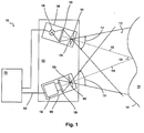
- the system 100 includes an optical unit 102 and a computing device 104.
- the optical unit 102 produces structured light with one or more projectors 106.
- the projector 106 is a slide projector including a light source 126 and a light modulating device 122 for modulating the light emitted from the light source 126.
- the light modulating device 122 may be a slide-type including a slide, a liquid crystal display (LCD)-type including a liquid crystal screen, or other device for creating structured light, where such device will be hereinafter referred to as slide 122.
- LCD liquid crystal display
- the projector further includes a lens 181 having a vertex 124 for projecting a slide image as structured light 113 about a light cone 114 onto the surface 110 of an object 111 being measured.
- the structured light 113 can also be generated using other methods, such as interferential, moir and diffractive light generation methods.
- the projector 106 projects structured light in a wavelength selected from one of optical, visible and infrared wavelengths. In one or more embodiments, the projector 106 comprises a flashlight. In one or more embodiments, the projector 106 is a continuous light source.
- the optical unit 102 includes a camera 108 or other image detecting device for capturing an image of the structured light 113 acting on the surface 110 of the object 111.
- the camera 108 includes a lens 180 having a vertex 130, a matrix radiation receiver 128 and a camera driver 132.
- the lens 180 forms the image on the surface of the matrix radiation receiver 128.
- the camera driver 132 functions as an electronic signal management and processing unit which controls operation of the matrix radiation receiver 128 and can convert the image captured by the receiver 128 to another format (e.g., VGA, bmp, jpeg, etc.) as desired or required before the captured image is transferred to the camera output 134.
- the camera 108 includes a field of view 118 that encompasses a portion of the surface 110 of the object 111.
- the projector 106 includes a central projector optical axis 112 and the camera 108 includes a central camera optical axis 116, such that the triangulation angle 120 is the angle extending between where the projector optical axis 112 and the camera optical axis 116 intersect.
- the computing device 104 analyzes the captured image received from the camera output 134 to perform the desired calculations, such as but not limited to the 3D shape of the surface 110 of the object 111, the distance to the object 111 and the orientation of the surface 110 being captured.
- the computing device 104 can also to control the projector 106 and the camera 108 and their various components included therein.
- the center 124 of the entrance and exit pupils of the projection lens 181 of the projector 106 are in one or more embodiments the vertex of the projected structured light 113, while the center 130 of the entrance and exit pupils of the lens 180 of the camera 108 are in one or more embodiments the vertex of the camera field of view 118.
- a plurality of points in the slide 122 are projected onto the surface 110 of an object 111 and then mapped one-to-one to respective points in the captured image that is captured by the camera 108.
- the position of each point in the captured image depends on a variety of factors, such as the distance to the surface 110 of object 111 and the shape and orientation of the surface 110 in relation to the optical unit 102.
- each point in the captured image is associated with a respective point in the slide 122 and then the shape, position and/or orientation of the surface 110 is derived from the coordinates of the points using triangulation techniques known to those skilled in the art.
- FIG. 2 illustrates one possible method of calculating the shape of a surface 110 at a certain point based on the corresponding points on the slide 122 and on the captured image at the receiver 128.
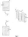
- FIG. 3 an illustrative example is provided showing a perspective view of how a projected image and a captured image are utilized to determine the shape of the surface 110 of an object 111.
- a slide 122 having a pattern of lines 162 performs amplitude modulation of the projected light from the light source 126 to project the pattern as structured light 113 from the projector 106 onto the surface 110 of the object 111.
- a pattern of lines 186 then appears on the surface 110.
- the camera 108 records the corresponding resulting captured image 140 of the structured light 113 acting on the surface 110.
- the complexity of calculating the shape of the surface 110 resides in the complexity of identifying correspondence between lines 185 in the pattern in the captured image 140 and lines 162 in the pattern in the slide 122.
- the projected light 113 can be structured to represent an assemblage of distinct elements that can be identified in the captured image 140.
- the introduction of this heterogeneity into the captured image 140 is termed "coding.”
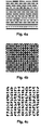
- FIGS. 4A-4C illustrates several non-claimed examples of coded structured light 113 that can be projected onto the surface 110 of the object 111.
- the task of identifying elements of structured light in an image captured by the camera 108 is still complex, especially due to the presence of perspective deformation caused by the finiteness of the distance between the object's surface 110 and the projector 106 and the camera 108.
- Perspective deformation distorts the captured image 140 of the structured light 113 in two directions and depends on the shape of the surface 110 in each point of the captured image 140.
- each element of the projected structured light 113 may unpredictably shift, turn or twist its shape in the captured image 140, so that its identification will require a two-dimensional search in the captured image 140 considering all of its possible deformations (turn, shape deformation).
- the complexity associated with such a search often leads to frequent errors in the detection of structured light elements in the captured image 140, which results in errors measuring the shape of the object's surface 110.
- the searching task also requires resource-intensive search algorithms, which protracts registration time or requires a more powerful, and hence larger and more expensive, computational system or computing device 104.
- the system 100 simplifies the task of detecting elements of structured light 113 in the image 140 captured by the camera 108 by restricting the number of directions in which the structured light 113 can be deformed to one known direction, organizing a code sequence of structured light 113 in that direction, and by using special structured light coding methods, thereby achieving more effective and efficient 3D imaging.
- affine epipolar geometry Based on affine epipolar geometry, if two cameras are looking at the same object or scene, it is possible to draw a straight line through each point in the image of the one camera, with all points of the object or scene corresponding to that line lying along a straight line in the image of the other camera, regardless of the shape of the object or scene.
- This principle can be applied to surface shape scanning using structured-light triangulation to determine the 3D shape of a material object.
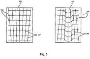
- the system 100 and associated method for the 3D measurement of the shape of material objects uses the assumption that, regardless of the position of the projector 106 and the camera 108 in relation to each other, it is possible to draw a straight line 187 through each point of the slide 122, such that, when the projected pattern in the structured light 113 is projected on the surface 110 of the object 111, a corresponding straight line 188 exists in the image 140 captured by the camera 108, regardless of the shape of the surface 110 being captured.
- any pair of such lines 187 and 188 forms a one-to-one correspondence, where such lines will be referred to as “meridians” hereafter and, in particular, as “camera meridians 188" for the captured image by the camera 108 and as “projector meridians 187” for the projected structured light 113 from the projector 106, as illustrated by way of example in FIG. 5 .
- the projector meridians 187 and camera meridians 188 are representative lines that can be represented on the surfaces of the slide 122 and the matrix radiation receiver 128, but they are not actually part of the pattern that is projected onto the object 111 and captured by the camera 108.
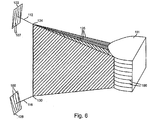
- the position of the meridians 187 is determined by projecting the structured light 113 from the projector lens 181 onto the surface 110 of the object 111, where each of the projector meridians 187 will lie in a plane 125 that extends from the vertex 124 of the structured light 113 projected from the projector 106 to the surface 110.
- Each of the camera meridians 188 in the matrix radiation receiver 128 will also lie in a respective one of the planes 125 that also extends from the vertex 130 of the camera field of view 118 of the camera 108 in the space of the object 111.
- the projector and camera meridians 187 and 188 lying in the same plane 125 in the space of the object 111 form a corresponding pair.
- the projector and camera meridians 187 and 188 there are direct interrelationship between the projector and camera meridians 187 and 188 and the planes 125 that extend from the vertices 124 and 130.
- the planes 125 could be considered similar to a light track for the projector and camera meridians 187 and 188 in the space of the object 111.
- the projector and camera meridians 187 and 188 can be considered images of the planes 125 on the slide 122 and matrix radiation receiver 128 surfaces made by the projector and camera lenses 180 and 181.
- a line 150 connecting the vertex 124 of the structured light 113 projected from the projector 106 with the vertex 130 of the field of view 118 of the camera 108 is perpendicular to the projector optical axis 112.
- the projector meridians 187 are strictly parallel, where an illustration of the projector and camera meridians 187 and 188 corresponding to this embodiment are provided in FIG. 8 .
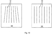
- a line 152 connecting the vertex 124 of the structured light 113 projected from the projector 106 with the vertex 130 of the field of view 118 of the camera 108 is perpendicular to the camera optical axis 116.
- the camera meridians 187 are strictly parallel, where an illustration of the projector and camera meridians 187 and 188 corresponding to this embodiment are provided in FIG. 10 .
- a line 154 connecting the vertex 124 of the central projection 113 of the projector 106 with the vertex 130 of the central projection 118 of the camera 108 is not perpendicular to either the projector optical axis 112 or the camera optical axis 116.
- neither the projector meridians 187 nor the camera meridians 188 are required to be strictly parallel, as illustrated in FIG. 12 .
- the structured light 113 projected by the projector 106 can be organized to restrict the number of possible directions and deformations in the captured image, thereby simplifying the task of identifying structured light elements in the captured image and, in certain cases, achieving complete linearization of the surface shape calculation algorithm.
- the number of possible directions and deformations is restricted to one among the meridians.
- the slide 122 is selected such that structured light 113 is formed possessing at least two coded elements that lie within a plane 125 passing through the vertices 124, 130 of the projector 106 and the camera 108.
- the structured light 113 can be formed as a pattern including a plurality of different groups of coded elements, wherein all of the coded elements in each group of coded elements lie within the same respective plane 125 passing through the vertices 124, 130 of the projector 106 and the camera 108. Different groups of coded elements will lie in different planes 125. In one or more examples such coded elements could be represented by regions with of varying shape, form and/or length.
- the structured light 113 is formed as a structure 160 possessing two coded elements 164 and 165 represented by regions of different thickness.
- the coded elements are located one by one along the plurality of parallel lines 162 so that their sequence within each line 162 forms a solid line with varying thicknesses of varying lengths.
- all the coded elements lie on a plurality of parallel meridians 187 that jointly with lines 162 form a grid.
- a group including a sequence of coded regions 164 and 165 of different thicknesses along each meridian 187 will form a unique sequence relative to the sequences of coded regions 164 and 165 in the other adjacent meridian 187. It is understood that other types of patterns can be generated to generate the coded elements or coded regions 164 and 165 in the structured light 113.
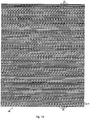
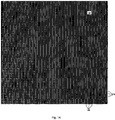
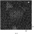
- FIGS. 14 and 15 portions of representative captured images 140 recorded by the camera 108 based on the relational positioning of the projector 106 and camera 108 of FIG. 7 are illustrated in FIGS. 14 and 15 for representative planar objects ( FIG. 14 ) and non-planar objects ( FIG.15 ). From these figures, it can be seen that groups of coded elements 164 and 165 each lie on a respective projector meridian 187 in the slide 122 and will also lie with a respective camera meridian 188 in the image 140 (where the projector meridians 187 and the camera meridians 188 are illustrated as vertical lines in these figures).
- the particular shape of the surface 110 of the object 111 being analyzed will cause the coded elements 164 and 165 in the image 140 to move only in a direction along the length of the camera meridians 188.
- a desired 3D measurement of the surface 110 can then be made by analyzing the movement and/or position of coded elements 164 along the camera meridians 188 with respect to the position of the respective coded elements 164 and 165 in the slide 122 and also with respect to the movement and/or position of the other coded elements 164 and 165 in the same group of coded elements 164 or 165 along the same or different camera meridians 188.
- the structure 160 may be used for any of embodiments described herein. To be used for a particular embodiment, the structure 160 should be fit into a field of the slide 122 by zooming, shifting or otherwise altering the structure 160. In addition, the structure 160 may be distorted as necessary so that groups of coded elements 164 and 165 of the structure 160 coincide with meridians chosen for the particular embodiment.
- the computing system 104 may comprise a general-purpose computer system which is suitable for implementing the method for the 3D measurement of the shape of material objects in accordance with the present disclosure.
- the computing system 104 is only one example of a suitable computing environment and is not intended to suggest any limitation as to the scope of use or functionality of the invention.
- the present system and method for the 3D measurement of the shape of material objects is operational with numerous other general purpose or special purpose computing system environments or configurations.
- Examples of well known computing systems, environments, and/or configurations that may be suitable for use with the invention include, but are not limited to, personal computers, server computers, handheld or laptop devices, multiprocessor systems, microprocessor-based systems, programmable consumer electronics, networked PCs, minicomputers, mainframe computers, distributed computing environments that include any of the above systems or devices, and the like.
- the triangulation algorithms and the method for the 3D measurement of the shape of material objects may be described in the general context of computer-executable instructions, such as program modules, being executed by a computer.
- program modules include routines, programs, objects, components, data structures, etc. that perform particular tasks or implement particular abstract data types. These algorithms and methods may also be practiced in distributed computing environments where tasks are performed by remote processing devices that are linked through a communications network.
- program modules may be located in both local and remote computer storage media including memory storage devices.
- the computing system 104 implements 3D shape measurement of objects by executing one or more computer programs.
- the computer programs may be stored in a memory medium or storage medium such as a memory and/or ROM, or they may be provided to a CPU through a network connection or other I/O connection.
- the system and method formed in accordance with the embodiments described herein provide for the 3D measurement of the shape of material objects using non-contact structured light triangulation.
- Such a system and method are capable of quickly and accurately measuring the coordinates of a point cloud (i.e., light structure) projected on the surface of complex-shaped material objects in one coordinate system referenced to the system.
- These teachings can be applied to a whole range of scientific and engineering problems that require accurate data about the surface shape of an object, distance to the surface, or its spatial orientation.
- the present system and method has useful applications in many fields, including but not limited to digital imaging, the control of part shapes, computer animation, capturing the shape of objects that have cultural, historical or scientific value, shape recognition, topography, machine vision, medical procedures, special positioning of devices and robots, etc.
Landscapes
- Engineering & Computer Science (AREA)
- Physics & Mathematics (AREA)
- General Physics & Mathematics (AREA)
- Computer Vision & Pattern Recognition (AREA)
- Computer Graphics (AREA)
- Theoretical Computer Science (AREA)
- Length Measuring Devices By Optical Means (AREA)
Priority Applications (1)
| Application Number | Priority Date | Filing Date | Title |
|---|---|---|---|
| PL08829922T PL2188589T3 (pl) | 2007-08-28 | 2008-08-26 | System i sposób do trójwymiarowego pomiaru kształtu obiektów materialnych |
Applications Claiming Priority (2)
| Application Number | Priority Date | Filing Date | Title |
|---|---|---|---|
| US11/846,494 US7768656B2 (en) | 2007-08-28 | 2007-08-28 | System and method for three-dimensional measurement of the shape of material objects |
| PCT/US2008/074354 WO2009032641A1 (en) | 2007-08-28 | 2008-08-26 | System and method for three-dimensional measurement of the shape of material objects |
Publications (3)
| Publication Number | Publication Date |
|---|---|
| EP2188589A1 EP2188589A1 (en) | 2010-05-26 |
| EP2188589A4 EP2188589A4 (en) | 2017-03-29 |
| EP2188589B1 true EP2188589B1 (en) | 2020-04-15 |
Family
ID=40406938
Family Applications (1)
| Application Number | Title | Priority Date | Filing Date |
|---|---|---|---|
| EP08829922.7A Active EP2188589B1 (en) | 2007-08-28 | 2008-08-26 | System and method for three-dimensional measurement of the shape of material objects |
Country Status (13)
| Country | Link |
|---|---|
| US (1) | US7768656B2 (pl) |
| EP (1) | EP2188589B1 (pl) |
| JP (1) | JP5643645B2 (pl) |
| KR (1) | KR101601331B1 (pl) |
| CN (1) | CN101821580B (pl) |
| AU (1) | AU2008296518B2 (pl) |
| DK (1) | DK2188589T3 (pl) |
| ES (1) | ES2801395T3 (pl) |
| HU (1) | HUE049584T2 (pl) |
| MX (1) | MX2010002346A (pl) |
| PL (1) | PL2188589T3 (pl) |
| RU (1) | RU2521725C2 (pl) |
| WO (1) | WO2009032641A1 (pl) |
Families Citing this family (65)
| Publication number | Priority date | Publication date | Assignee | Title |
|---|---|---|---|---|
| CA2670214A1 (en) | 2006-11-21 | 2008-05-29 | Mantisvision Ltd. | 3d geometric modeling and 3d video content creation |
| US8090194B2 (en) | 2006-11-21 | 2012-01-03 | Mantis Vision Ltd. | 3D geometric modeling and motion capture using both single and dual imaging |
| CA2606267A1 (fr) * | 2007-10-11 | 2009-04-11 | Hydro-Quebec | Systeme et methode de cartographie tridimensionnelle d'une surface structurelle |
| FR2925706B1 (fr) * | 2007-12-19 | 2010-01-15 | Soc Tech Michelin | Dispositif d'evaluation de la surface d'un pneumatique. |
| US8531650B2 (en) | 2008-07-08 | 2013-09-10 | Chiaro Technologies LLC | Multiple channel locating |
| US8294762B2 (en) * | 2008-10-10 | 2012-10-23 | Fujifilm Corporation | Three-dimensional shape measurement photographing apparatus, method, and program |
| US8339616B2 (en) * | 2009-03-31 | 2012-12-25 | Micrometric Vision Technologies | Method and apparatus for high-speed unconstrained three-dimensional digitalization |
| FR2950157A1 (fr) | 2009-09-15 | 2011-03-18 | Noomeo | Procede de numerisation tridimensionnelle d'une surface comprenant laprojection d'un motif combine |
| FR2950140B1 (fr) | 2009-09-15 | 2011-10-21 | Noomeo | Procede de numerisation tridimensionnelle comprenant une double mise en correspondance |
| JP5631025B2 (ja) * | 2010-03-10 | 2014-11-26 | キヤノン株式会社 | 情報処理装置、その処理方法及びプログラム |
| US8649025B2 (en) | 2010-03-27 | 2014-02-11 | Micrometric Vision Technologies | Methods and apparatus for real-time digitization of three-dimensional scenes |
| US8467992B1 (en) | 2010-09-15 | 2013-06-18 | The Boeing Company | Vision based location and measurement device and methods |
| KR101188357B1 (ko) * | 2011-04-21 | 2012-10-08 | 정제교 | 기설정 배율각을 가진 다중투사광의 2차원 영상획득을 통한 3차원 인식 방법 |
| JP6170281B2 (ja) * | 2011-05-10 | 2017-07-26 | キヤノン株式会社 | 三次元計測装置、三次元計測装置の制御方法、およびプログラム |
| EP2718668B1 (en) | 2011-06-07 | 2023-07-26 | Creaform Inc. | Sensor positioning for 3d scanning |
| JP6061631B2 (ja) * | 2011-07-11 | 2017-01-18 | キヤノン株式会社 | 計測装置、情報処理装置、計測方法、情報処理方法、および、プログラム |
| KR101268515B1 (ko) * | 2011-07-22 | 2013-06-04 | 경북대학교 산학협력단 | 3차원 스캔 장치 및 3차원 형상 복원 방법 |
| CN102506704B (zh) * | 2011-10-14 | 2013-12-25 | 天津大学 | 一种压缩弹簧几何参数在线测量方法 |
| JP6023415B2 (ja) * | 2011-10-17 | 2016-11-09 | キヤノン株式会社 | 三次元計測装置、三次元計測装置の制御方法およびプログラム |
| JP5635218B1 (ja) | 2011-11-23 | 2014-12-03 | クレアフォーム・インコーポレイテッドCreaform Inc. | 空間コード化スライド画像に対するパターンのアライメント方法およびシステム |
| US9207070B2 (en) * | 2012-05-24 | 2015-12-08 | Qualcomm Incorporated | Transmission of affine-invariant spatial mask for active depth sensing |
| CN104583713B (zh) * | 2012-06-29 | 2019-04-19 | Inb视觉股份公司 | 使优选是结构化的物体表面成像的方法及用于成像的装置 |
| US9816809B2 (en) | 2012-07-04 | 2017-11-14 | Creaform Inc. | 3-D scanning and positioning system |
| US8937657B2 (en) * | 2012-07-15 | 2015-01-20 | Erik Klass | Portable three-dimensional metrology with data displayed on the measured surface |
| EP2875314B1 (en) | 2012-07-18 | 2017-08-16 | Creaform Inc. | System and method for 3d scanning of the surface geometry of an object |
| JP6270157B2 (ja) | 2012-07-30 | 2018-01-31 | 国立研究開発法人産業技術総合研究所 | 画像処理システムおよび画像処理方法 |
| KR102070428B1 (ko) * | 2012-08-30 | 2020-01-28 | 삼성전자주식회사 | 물체의 형상 정보를 생성하는 방법 및 그 장치 |
| EP2918967B1 (en) | 2012-11-07 | 2018-05-16 | Artec Europe S.a.r.l. | Method for monitoring linear dimensions of three-dimensional objects |
| US20140152771A1 (en) * | 2012-12-01 | 2014-06-05 | Og Technologies, Inc. | Method and apparatus of profile measurement |
| US20140152769A1 (en) * | 2012-12-05 | 2014-06-05 | Paul Atwell | Three-dimensional scanner and method of operation |
| DE102012222505B4 (de) | 2012-12-07 | 2017-11-09 | Michael Gilge | Verfahren zum Erfassen dreidimensionaler Daten eines zu vermessenden Objekts, Verwendung eines derartigen Verfahrens zur Gesichtserkennung und Vorrichtung zur Durchführung eines derartigen Verfahrens |
| US9047514B2 (en) | 2013-07-10 | 2015-06-02 | Christie Digital Systems Usa, Inc. | Apparatus, system and method for projecting images onto predefined portions of objects |
| US9049369B2 (en) | 2013-07-10 | 2015-06-02 | Christie Digital Systems Usa, Inc. | Apparatus, system and method for projecting images onto predefined portions of objects |
| ES2719492T3 (es) * | 2013-07-16 | 2019-07-10 | Polyrix Inc | Sistema de inspección para inspeccionar un objeto y método de inspección para el mismo |
| US9562760B2 (en) | 2014-03-10 | 2017-02-07 | Cognex Corporation | Spatially self-similar patterned illumination for depth imaging |
| US20150278155A1 (en) | 2014-03-27 | 2015-10-01 | Knockout Concepts, Llc | Identifying objects using a 3d scanning device, images, and 3d models |
| CN103955064A (zh) * | 2014-04-17 | 2014-07-30 | 长沙中科院文化创意与科技产业研究院 | 一种投射多光点图像的装置及方法 |
| CN106796661B (zh) * | 2014-08-12 | 2020-08-25 | 曼蒂斯影像有限公司 | 投影光图案的系统、方法和计算机程序产品 |
| US10571668B2 (en) | 2015-05-09 | 2020-02-25 | Cognex Corporation | Catadioptric projector systems, devices, and methods |
| CN105043253B (zh) * | 2015-06-18 | 2018-06-05 | 中国计量大学 | 基于面结构光技术货车侧防护栏安装尺寸测量系统及方法 |
| RU2629541C2 (ru) * | 2015-11-09 | 2017-08-29 | АРТЕК ЮРОП С.а.р.Л. | Бесконтактное биометрическое устройство идентификации пользователя по чертам лица |
| US11057608B2 (en) * | 2016-01-04 | 2021-07-06 | Qualcomm Incorporated | Depth map generation in structured light system |
| DE102016002398B4 (de) | 2016-02-26 | 2019-04-25 | Gerd Häusler | Optischer 3D-Sensor zur schnellen und dichten Formerfassung |
| DE102016113228A1 (de) * | 2016-07-18 | 2018-01-18 | Ensenso GmbH | System mit Kamera, Projektor und Auswerteeinrichtung |
| WO2018027259A1 (en) | 2016-08-08 | 2018-02-15 | Bionics Institute | Systems and methods for monitoring neural activity |
| EP3315902B1 (de) * | 2016-10-27 | 2023-09-06 | Pepperl+Fuchs SE | Messvorrichtung und verfahren zur triangulationsmessung |
| LU100021B1 (en) | 2017-01-13 | 2018-07-30 | Adapttech Ltd | Socket fitting system |
| US10122997B1 (en) | 2017-05-03 | 2018-11-06 | Lowe's Companies, Inc. | Automated matrix photo framing using range camera input |
| JP7144450B2 (ja) | 2017-05-22 | 2022-09-29 | ディープ・ブレイン・スティムレーション・テクノロジーズ・ピーティーワイ・リミテッド | 神経活動をモニタするためのシステム及び方法 |
| US10699429B2 (en) | 2017-08-19 | 2020-06-30 | Cognex Corporation | Coding distance topologies for structured light patterns for 3D reconstruction |
| CN109635619B (zh) | 2017-08-19 | 2021-08-31 | 康耐视公司 | 用于三维重建的结构化光图案的编码距离拓扑 |
| EP3701283B1 (en) * | 2017-10-22 | 2025-04-16 | Magik Eye Inc. | Adjusting the projection system of a distance sensor to optimize a beam layout |
| CN108627119B (zh) * | 2018-05-15 | 2020-09-25 | 佛山市南海区广工大数控装备协同创新研究院 | 一种基于线扫激光的板式家具轮廓尺寸检测方法 |
| CN108776338B (zh) * | 2018-06-19 | 2022-05-24 | 四川大学 | 信号源空间传感方法、装置及主动式传感系统 |
| CN113538652B (zh) | 2018-09-19 | 2022-07-19 | 阿泰克欧洲公司 | 具有数据收集反馈的三维扫描器 |
| WO2020073065A1 (en) * | 2018-10-04 | 2020-04-09 | Du Preez Isak | Optical surface encoder |
| WO2020161540A1 (en) | 2019-02-05 | 2020-08-13 | Artec Europe S.A R.L. | Generation of texture models using a moveable scanner |
| CN111751838B (zh) * | 2019-03-28 | 2025-06-06 | 上海小瞳智能科技有限公司 | 一种微型固态激光雷达及其数据处理方法 |
| US20220230335A1 (en) * | 2021-01-20 | 2022-07-21 | Nicolae Paul Teodorescu | One-shot high-accuracy geometric modeling of three-dimensional scenes |
| CN116105627B (zh) * | 2021-11-09 | 2026-03-24 | 华为技术有限公司 | 一种测量方法以及测量系统 |
| CN114413787B (zh) * | 2022-01-21 | 2024-04-19 | 西安知微传感技术有限公司 | 基于结构光的三维测量方法及大景深三维深度相机系统 |
| CN118974512A (zh) * | 2022-05-20 | 2024-11-15 | 形创有限公司 | 具有结构光图案投射器的3d扫描仪及用其执行光图案匹配和3d重构的方法 |
| GB2633493A (en) | 2022-05-26 | 2025-03-12 | Gemological Inst Of America Inc | Digital image gemstone verification with filters |
| US12211161B2 (en) | 2022-06-24 | 2025-01-28 | Lowe's Companies, Inc. | Reset modeling based on reset and object properties |
| US12189915B2 (en) | 2022-06-24 | 2025-01-07 | Lowe's Companies, Inc. | Simulated environment for presenting virtual objects and virtual resets |
Citations (1)
| Publication number | Priority date | Publication date | Assignee | Title |
|---|---|---|---|---|
| US20040005092A1 (en) * | 2002-06-19 | 2004-01-08 | Carlo Tomasi | Coded-array technique for obtaining depth and other position information of an observed object |
Family Cites Families (29)
| Publication number | Priority date | Publication date | Assignee | Title |
|---|---|---|---|---|
| US4648717A (en) * | 1984-02-06 | 1987-03-10 | Robotic Vision Systems, Inc. | Method of three-dimensional measurement with few projected patterns |
| JPH02110305A (ja) * | 1988-10-19 | 1990-04-23 | Mitsubishi Electric Corp | 3次元計測装置 |
| DE4007500A1 (de) * | 1990-03-09 | 1991-09-12 | Zeiss Carl Fa | Verfahren und vorrichtung zur beruehrungslosen vermessung von objektoberflaechen |
| JPH0498106A (ja) * | 1990-08-16 | 1992-03-30 | Nippon Telegr & Teleph Corp <Ntt> | 3次元形状計測方法 |
| DE19638758A1 (de) * | 1996-09-13 | 1998-03-19 | Rubbert Ruedger | Verfahren und Vorrichtung zur dreidimensionalen Vermessung von Objekten |
| DE19821611A1 (de) * | 1998-05-14 | 1999-11-18 | Syrinx Med Tech Gmbh | Verfahren zur Erfassung der räumlichen Struktur einer dreidimensionalen Oberfläche |
| US6751344B1 (en) | 1999-05-28 | 2004-06-15 | Champion Orthotic Investments, Inc. | Enhanced projector system for machine vision |
| DE19963333A1 (de) | 1999-12-27 | 2001-07-12 | Siemens Ag | Verfahren zur Ermittlung von dreidimensionalen Oberflächenkoordinaten |
| GB2375392B (en) * | 2000-01-07 | 2004-12-15 | Cyberoptics Corp | Phase profilometry system with telecentric projector |
| US6937348B2 (en) * | 2000-01-28 | 2005-08-30 | Genex Technologies, Inc. | Method and apparatus for generating structural pattern illumination |
| JP3553451B2 (ja) | 2000-02-18 | 2004-08-11 | 独立行政法人 科学技術振興機構 | 光干渉断層像観測装置 |
| CA2306515A1 (en) * | 2000-04-25 | 2001-10-25 | Inspeck Inc. | Internet stereo vision, 3d digitizing, and motion capture camera |
| JP2001356010A (ja) * | 2000-06-12 | 2001-12-26 | Asahi Hightech Kk | 三次元形状測定装置 |
| US7625335B2 (en) | 2000-08-25 | 2009-12-01 | 3Shape Aps | Method and apparatus for three-dimensional optical scanning of interior surfaces |
| JP3519698B2 (ja) | 2001-04-20 | 2004-04-19 | 照明 與語 | 3次元形状測定方法 |
| JP2003057191A (ja) | 2001-08-20 | 2003-02-26 | Ricoh Co Ltd | 円筒状被検物形状測定装置及び該円筒状被検物形状測定装置の調整方法と信号処理方法 |
| WO2003078927A1 (fr) | 2002-03-18 | 2003-09-25 | A4 Vision Sa | Dispositif de mesure sans contact des dimensions lineaires d'objets tridimensionnels |
| JP2004077290A (ja) * | 2002-08-19 | 2004-03-11 | Fuji Xerox Co Ltd | 3次元形状計測装置および方法 |
| US7286246B2 (en) * | 2003-03-31 | 2007-10-23 | Mitutoyo Corporation | Method and apparatus for non-contact three-dimensional surface measurement |
| JP4391137B2 (ja) * | 2003-06-10 | 2009-12-24 | Jfeテクノリサーチ株式会社 | 3次元曲面形状の測定装置及び測定方法 |
| JP3792679B2 (ja) * | 2003-06-23 | 2006-07-05 | Necビューテクノロジー株式会社 | 投射面距離測定装置を有するプロジェクタ |
| JP4480488B2 (ja) * | 2003-08-28 | 2010-06-16 | 富士通株式会社 | 計測装置、コンピュータ数値制御装置及びプログラム |
| US7330577B2 (en) * | 2004-01-27 | 2008-02-12 | Densys Ltd. | Three-dimensional modeling of the oral cavity by projecting a two-dimensional array of random patterns |
| US7525669B1 (en) * | 2004-07-09 | 2009-04-28 | Mohsen Abdollahi | High-speed, scanning phase-shifting profilometry using 2D CMOS sensor |
| DE102005018656B4 (de) * | 2005-04-21 | 2007-04-12 | GOM - Gesellschaft für Optische Meßtechnik mbH | Projektor für eine Anordnung zum dreidimensionalen optischen Vermessen von Objekten |
| JP4577126B2 (ja) * | 2005-07-08 | 2010-11-10 | オムロン株式会社 | ステレオ対応づけのための投光パターンの生成装置及び生成方法 |
| PL1969307T3 (pl) * | 2005-11-28 | 2010-12-31 | 3Shape As | Kodowane światło strukturalne |
| JP4741943B2 (ja) | 2005-12-13 | 2011-08-10 | ルネサスエレクトロニクス株式会社 | 検査装置及び検査方法 |
| JP2008275392A (ja) * | 2007-04-26 | 2008-11-13 | National Institute Of Advanced Industrial & Technology | 3次元形状計測方法および装置 |
-
2007
- 2007-08-28 US US11/846,494 patent/US7768656B2/en active Active
-
2008
- 2008-08-26 PL PL08829922T patent/PL2188589T3/pl unknown
- 2008-08-26 JP JP2010523096A patent/JP5643645B2/ja active Active
- 2008-08-26 AU AU2008296518A patent/AU2008296518B2/en active Active
- 2008-08-26 MX MX2010002346A patent/MX2010002346A/es active IP Right Grant
- 2008-08-26 HU HUE08829922A patent/HUE049584T2/hu unknown
- 2008-08-26 ES ES08829922T patent/ES2801395T3/es active Active
- 2008-08-26 KR KR1020107006831A patent/KR101601331B1/ko active Active
- 2008-08-26 EP EP08829922.7A patent/EP2188589B1/en active Active
- 2008-08-26 CN CN200880110585.5A patent/CN101821580B/zh active Active
- 2008-08-26 RU RU2010111797/28A patent/RU2521725C2/ru active IP Right Revival
- 2008-08-26 DK DK08829922.7T patent/DK2188589T3/da active
- 2008-08-26 WO PCT/US2008/074354 patent/WO2009032641A1/en not_active Ceased
Patent Citations (1)
| Publication number | Priority date | Publication date | Assignee | Title |
|---|---|---|---|---|
| US20040005092A1 (en) * | 2002-06-19 | 2004-01-08 | Carlo Tomasi | Coded-array technique for obtaining depth and other position information of an observed object |
Also Published As
| Publication number | Publication date |
|---|---|
| RU2521725C2 (ru) | 2014-07-10 |
| MX2010002346A (es) | 2010-08-04 |
| PL2188589T3 (pl) | 2020-11-16 |
| ES2801395T3 (es) | 2021-01-11 |
| JP5643645B2 (ja) | 2014-12-17 |
| DK2188589T3 (da) | 2020-06-15 |
| RU2010111797A (ru) | 2011-10-10 |
| WO2009032641A1 (en) | 2009-03-12 |
| JP2010538269A (ja) | 2010-12-09 |
| KR101601331B1 (ko) | 2016-03-08 |
| US7768656B2 (en) | 2010-08-03 |
| EP2188589A4 (en) | 2017-03-29 |
| HUE049584T2 (hu) | 2020-09-28 |
| EP2188589A1 (en) | 2010-05-26 |
| KR20100087083A (ko) | 2010-08-03 |
| AU2008296518B2 (en) | 2014-01-23 |
| CN101821580A (zh) | 2010-09-01 |
| AU2008296518A1 (en) | 2009-03-12 |
| US20090059241A1 (en) | 2009-03-05 |
| CN101821580B (zh) | 2016-11-16 |
Similar Documents
| Publication | Publication Date | Title |
|---|---|---|
| EP2188589B1 (en) | System and method for three-dimensional measurement of the shape of material objects | |
| CN103649674B (zh) | 测量设备以及信息处理设备 | |
| US20130106833A1 (en) | Method and apparatus for optical tracking of 3d pose using complex markers | |
| US20090067706A1 (en) | System and Method for Multiframe Surface Measurement of the Shape of Objects | |
| US12067083B2 (en) | Detecting displacements and/or defects in a point cloud using cluster-based cloud-to-cloud comparison | |
| Tanaka et al. | Solving pose ambiguity of planar visual marker by wavelike two-tone patterns | |
| JP6486083B2 (ja) | 情報処理装置、情報処理方法及びプログラム | |
| Zhang et al. | Structured light based 3d scanning for specular surface by the combination of gray code and phase shifting | |
| Shi et al. | Large-scale three-dimensional measurement based on LED marker tracking | |
| Yamauchi et al. | Calibration of a structured light system by observing planar object from unknown viewpoints | |
| US12322169B2 (en) | Defect detection in a point cloud | |
| JP4382430B2 (ja) | 頭部の三次元形状計測システム | |
| Orghidan et al. | Modelling and accuracy estimation of a new omnidirectional depth computation sensor | |
| Ahsan et al. | Grid-Index-Based Three-Dimensional Profilometry | |
| HK1148064B (en) | System and method for three-dimensional measurement of the shape of material objects | |
| HK1148064A (en) | System and method for three-dimensional measurement of the shape of material objects | |
| Damirchi et al. | Aras-iref: An open-source low-cost framework for pose estimation | |
| Zhang et al. | An efficient method for dynamic calibration and 3D reconstruction using homographic transformation | |
| US12198414B2 (en) | Upscaling triangulation scanner images to reduce noise | |
| Lee et al. | A new 3d sensor system for mobile robots based on moire and stereo vision technique | |
| Mark | A Monocular Vision-based System Using Markers for a Real-Time 6D Pose Estimation of a Trailer | |
| Lee et al. | System input–output theoretic three-dimensional measurement based on circular-shaped structured light patterns | |
| Van Crombrugge et al. | Extrinsic Camera Calibration with Line-Laser Projection | |
| Jaspers et al. | Sift-based Camera Localization using Reference Objects for Application in Multi-camera Environments and Robotics. | |
| Lee et al. | A new 3D sensing method based on stereo PMP technique for mobile robots |
Legal Events
| Date | Code | Title | Description |
|---|---|---|---|
| PUAI | Public reference made under article 153(3) epc to a published international application that has entered the european phase |
Free format text: ORIGINAL CODE: 0009012 |
|
| 17P | Request for examination filed |
Effective date: 20100325 |
|
| AK | Designated contracting states |
Kind code of ref document: A1 Designated state(s): AT BE BG CH CY CZ DE DK EE ES FI FR GB GR HR HU IE IS IT LI LT LU LV MC MT NL NO PL PT RO SE SI SK TR |
|
| AX | Request for extension of the european patent |
Extension state: AL BA MK RS |
|
| DAX | Request for extension of the european patent (deleted) | ||
| RAP1 | Party data changed (applicant data changed or rights of an application transferred) |
Owner name: ARTEC EUROPE S.A.R.L. |
|
| REG | Reference to a national code |
Ref country code: DE Ref legal event code: R079 Ref document number: 602008062519 Country of ref document: DE Free format text: PREVIOUS MAIN CLASS: G01B0011240000 Ipc: G01B0011250000 |
|
| RA4 | Supplementary search report drawn up and despatched (corrected) |
Effective date: 20170228 |
|
| RIC1 | Information provided on ipc code assigned before grant |
Ipc: G01B 11/25 20060101AFI20170222BHEP |
|
| STAA | Information on the status of an ep patent application or granted ep patent |
Free format text: STATUS: EXAMINATION IS IN PROGRESS |
|
| 17Q | First examination report despatched |
Effective date: 20181005 |
|
| GRAP | Despatch of communication of intention to grant a patent |
Free format text: ORIGINAL CODE: EPIDOSNIGR1 |
|
| STAA | Information on the status of an ep patent application or granted ep patent |
Free format text: STATUS: GRANT OF PATENT IS INTENDED |
|
| INTG | Intention to grant announced |
Effective date: 20191010 |
|
| GRAS | Grant fee paid |
Free format text: ORIGINAL CODE: EPIDOSNIGR3 |
|
| GRAA | (expected) grant |
Free format text: ORIGINAL CODE: 0009210 |
|
| STAA | Information on the status of an ep patent application or granted ep patent |
Free format text: STATUS: THE PATENT HAS BEEN GRANTED |
|
| RAP1 | Party data changed (applicant data changed or rights of an application transferred) |
Owner name: ARTEC EUROPE S.A R.L. |
|
| AK | Designated contracting states |
Kind code of ref document: B1 Designated state(s): AT BE BG CH CY CZ DE DK EE ES FI FR GB GR HR HU IE IS IT LI LT LU LV MC MT NL NO PL PT RO SE SI SK TR |
|
| REG | Reference to a national code |
Ref country code: GB Ref legal event code: FG4D Ref country code: CH Ref legal event code: EP |
|
| REG | Reference to a national code |
Ref country code: DE Ref legal event code: R096 Ref document number: 602008062519 Country of ref document: DE |
|
| REG | Reference to a national code |
Ref country code: IE Ref legal event code: FG4D |
|
| REG | Reference to a national code |
Ref country code: AT Ref legal event code: REF Ref document number: 1257837 Country of ref document: AT Kind code of ref document: T Effective date: 20200515 |
|
| REG | Reference to a national code |
Ref country code: DK Ref legal event code: T3 Effective date: 20200611 |
|
| REG | Reference to a national code |
Ref country code: CH Ref legal event code: NV Representative=s name: RENTSCH PARTNER AG, CH |
|
| REG | Reference to a national code |
Ref country code: FI Ref legal event code: FGE |
|
| REG | Reference to a national code |
Ref country code: NL Ref legal event code: FP |
|
| REG | Reference to a national code |
Ref country code: SE Ref legal event code: TRGR |
|
| REG | Reference to a national code |
Ref country code: LT Ref legal event code: MG4D |
|
| REG | Reference to a national code |
Ref country code: HU Ref legal event code: AG4A Ref document number: E049584 Country of ref document: HU |
|
| PG25 | Lapsed in a contracting state [announced via postgrant information from national office to epo] |
Ref country code: PT Free format text: LAPSE BECAUSE OF FAILURE TO SUBMIT A TRANSLATION OF THE DESCRIPTION OR TO PAY THE FEE WITHIN THE PRESCRIBED TIME-LIMIT Effective date: 20200817 Ref country code: LT Free format text: LAPSE BECAUSE OF FAILURE TO SUBMIT A TRANSLATION OF THE DESCRIPTION OR TO PAY THE FEE WITHIN THE PRESCRIBED TIME-LIMIT Effective date: 20200415 Ref country code: GR Free format text: LAPSE BECAUSE OF FAILURE TO SUBMIT A TRANSLATION OF THE DESCRIPTION OR TO PAY THE FEE WITHIN THE PRESCRIBED TIME-LIMIT Effective date: 20200716 Ref country code: NO Free format text: LAPSE BECAUSE OF FAILURE TO SUBMIT A TRANSLATION OF THE DESCRIPTION OR TO PAY THE FEE WITHIN THE PRESCRIBED TIME-LIMIT Effective date: 20200715 Ref country code: IS Free format text: LAPSE BECAUSE OF FAILURE TO SUBMIT A TRANSLATION OF THE DESCRIPTION OR TO PAY THE FEE WITHIN THE PRESCRIBED TIME-LIMIT Effective date: 20200815 |
|
| PG25 | Lapsed in a contracting state [announced via postgrant information from national office to epo] |
Ref country code: LV Free format text: LAPSE BECAUSE OF FAILURE TO SUBMIT A TRANSLATION OF THE DESCRIPTION OR TO PAY THE FEE WITHIN THE PRESCRIBED TIME-LIMIT Effective date: 20200415 Ref country code: HR Free format text: LAPSE BECAUSE OF FAILURE TO SUBMIT A TRANSLATION OF THE DESCRIPTION OR TO PAY THE FEE WITHIN THE PRESCRIBED TIME-LIMIT Effective date: 20200415 |
|
| REG | Reference to a national code |
Ref country code: ES Ref legal event code: FG2A Ref document number: 2801395 Country of ref document: ES Kind code of ref document: T3 Effective date: 20210111 |
|
| REG | Reference to a national code |
Ref country code: DE Ref legal event code: R097 Ref document number: 602008062519 Country of ref document: DE |
|
| PG25 | Lapsed in a contracting state [announced via postgrant information from national office to epo] |
Ref country code: RO Free format text: LAPSE BECAUSE OF FAILURE TO SUBMIT A TRANSLATION OF THE DESCRIPTION OR TO PAY THE FEE WITHIN THE PRESCRIBED TIME-LIMIT Effective date: 20200415 Ref country code: EE Free format text: LAPSE BECAUSE OF FAILURE TO SUBMIT A TRANSLATION OF THE DESCRIPTION OR TO PAY THE FEE WITHIN THE PRESCRIBED TIME-LIMIT Effective date: 20200415 |
|
| PLBE | No opposition filed within time limit |
Free format text: ORIGINAL CODE: 0009261 |
|
| STAA | Information on the status of an ep patent application or granted ep patent |
Free format text: STATUS: NO OPPOSITION FILED WITHIN TIME LIMIT |
|
| PG25 | Lapsed in a contracting state [announced via postgrant information from national office to epo] |
Ref country code: SK Free format text: LAPSE BECAUSE OF FAILURE TO SUBMIT A TRANSLATION OF THE DESCRIPTION OR TO PAY THE FEE WITHIN THE PRESCRIBED TIME-LIMIT Effective date: 20200415 |
|
| 26N | No opposition filed |
Effective date: 20210118 |
|
| PG25 | Lapsed in a contracting state [announced via postgrant information from national office to epo] |
Ref country code: MC Free format text: LAPSE BECAUSE OF FAILURE TO SUBMIT A TRANSLATION OF THE DESCRIPTION OR TO PAY THE FEE WITHIN THE PRESCRIBED TIME-LIMIT Effective date: 20200415 |
|
| PG25 | Lapsed in a contracting state [announced via postgrant information from national office to epo] |
Ref country code: SI Free format text: LAPSE BECAUSE OF FAILURE TO SUBMIT A TRANSLATION OF THE DESCRIPTION OR TO PAY THE FEE WITHIN THE PRESCRIBED TIME-LIMIT Effective date: 20200415 |
|
| PG25 | Lapsed in a contracting state [announced via postgrant information from national office to epo] |
Ref country code: IE Free format text: LAPSE BECAUSE OF NON-PAYMENT OF DUE FEES Effective date: 20200826 |
|
| REG | Reference to a national code |
Ref country code: AT Ref legal event code: UEP Ref document number: 1257837 Country of ref document: AT Kind code of ref document: T Effective date: 20200415 |
|
| PG25 | Lapsed in a contracting state [announced via postgrant information from national office to epo] |
Ref country code: MT Free format text: LAPSE BECAUSE OF FAILURE TO SUBMIT A TRANSLATION OF THE DESCRIPTION OR TO PAY THE FEE WITHIN THE PRESCRIBED TIME-LIMIT Effective date: 20200415 Ref country code: CY Free format text: LAPSE BECAUSE OF FAILURE TO SUBMIT A TRANSLATION OF THE DESCRIPTION OR TO PAY THE FEE WITHIN THE PRESCRIBED TIME-LIMIT Effective date: 20200415 |
|
| P01 | Opt-out of the competence of the unified patent court (upc) registered |
Effective date: 20230513 |
|
| PGFP | Annual fee paid to national office [announced via postgrant information from national office to epo] |
Ref country code: BG Payment date: 20240813 Year of fee payment: 17 |
|
| PGFP | Annual fee paid to national office [announced via postgrant information from national office to epo] |
Ref country code: DK Payment date: 20240826 Year of fee payment: 17 |
|
| PGFP | Annual fee paid to national office [announced via postgrant information from national office to epo] |
Ref country code: CH Payment date: 20240903 Year of fee payment: 17 |
|
| PGFP | Annual fee paid to national office [announced via postgrant information from national office to epo] |
Ref country code: AT Payment date: 20240801 Year of fee payment: 17 |
|
| PGFP | Annual fee paid to national office [announced via postgrant information from national office to epo] |
Ref country code: HU Payment date: 20240805 Year of fee payment: 17 |
|
| PGFP | Annual fee paid to national office [announced via postgrant information from national office to epo] |
Ref country code: SE Payment date: 20240827 Year of fee payment: 17 |
|
| PGFP | Annual fee paid to national office [announced via postgrant information from national office to epo] |
Ref country code: LU Payment date: 20250821 Year of fee payment: 18 Ref country code: NL Payment date: 20250821 Year of fee payment: 18 |
|
| PGFP | Annual fee paid to national office [announced via postgrant information from national office to epo] |
Ref country code: ES Payment date: 20250903 Year of fee payment: 18 Ref country code: FI Payment date: 20250821 Year of fee payment: 18 |
|
| PGFP | Annual fee paid to national office [announced via postgrant information from national office to epo] |
Ref country code: DE Payment date: 20250828 Year of fee payment: 18 |
|
| PGFP | Annual fee paid to national office [announced via postgrant information from national office to epo] |
Ref country code: TR Payment date: 20250822 Year of fee payment: 18 Ref country code: PL Payment date: 20250822 Year of fee payment: 18 Ref country code: IT Payment date: 20250829 Year of fee payment: 18 |
|
| PGFP | Annual fee paid to national office [announced via postgrant information from national office to epo] |
Ref country code: BE Payment date: 20250821 Year of fee payment: 18 Ref country code: GB Payment date: 20250822 Year of fee payment: 18 |
|
| PGFP | Annual fee paid to national office [announced via postgrant information from national office to epo] |
Ref country code: FR Payment date: 20250821 Year of fee payment: 18 |
|
| PGFP | Annual fee paid to national office [announced via postgrant information from national office to epo] |
Ref country code: CZ Payment date: 20250822 Year of fee payment: 18 |
|
| REG | Reference to a national code |
Ref country code: DK Ref legal event code: EBP Effective date: 20250831 |
|
| REG | Reference to a national code |
Ref country code: CH Ref legal event code: H13 Free format text: ST27 STATUS EVENT CODE: U-0-0-H10-H13 (AS PROVIDED BY THE NATIONAL OFFICE) Effective date: 20260324 |
|
| PG25 | Lapsed in a contracting state [announced via postgrant information from national office to epo] |
Ref country code: AT Free format text: LAPSE BECAUSE OF NON-PAYMENT OF DUE FEES Effective date: 20250826 |
|
| REG | Reference to a national code |
Ref country code: AT Ref legal event code: MM01 Ref document number: 1257837 Country of ref document: AT Kind code of ref document: T Effective date: 20250826 |
|
| PG25 | Lapsed in a contracting state [announced via postgrant information from national office to epo] |
Ref country code: HU Free format text: LAPSE BECAUSE OF NON-PAYMENT OF DUE FEES Effective date: 20250827 |
|
| PG25 | Lapsed in a contracting state [announced via postgrant information from national office to epo] |
Ref country code: CH Free format text: LAPSE BECAUSE OF NON-PAYMENT OF DUE FEES Effective date: 20250831 |