EP2188586B1 - Verfahren zum ausrichten von armreferenzsystemen einer mehrarm-messmaschine - Google Patents
Verfahren zum ausrichten von armreferenzsystemen einer mehrarm-messmaschine Download PDFInfo
- Publication number
- EP2188586B1 EP2188586B1 EP07827693.8A EP07827693A EP2188586B1 EP 2188586 B1 EP2188586 B1 EP 2188586B1 EP 07827693 A EP07827693 A EP 07827693A EP 2188586 B1 EP2188586 B1 EP 2188586B1
- Authority
- EP
- European Patent Office
- Prior art keywords
- measuring
- arm
- updating
- units
- measuring units
- Prior art date
- Legal status (The legal status is an assumption and is not a legal conclusion. Google has not performed a legal analysis and makes no representation as to the accuracy of the status listed.)
- Active
Links
- 238000000034 method Methods 0.000 title claims description 45
- 239000013598 vector Substances 0.000 claims description 27
- 239000011159 matrix material Substances 0.000 claims description 17
- 238000013519 translation Methods 0.000 claims description 9
- 238000001514 detection method Methods 0.000 claims 1
- 238000009434 installation Methods 0.000 description 2
- 238000005259 measurement Methods 0.000 description 2
- 230000002035 prolonged effect Effects 0.000 description 2
- 230000004308 accommodation Effects 0.000 description 1
- 230000000694 effects Effects 0.000 description 1
- 230000002708 enhancing effect Effects 0.000 description 1
- 230000007613 environmental effect Effects 0.000 description 1
- 230000002452 interceptive effect Effects 0.000 description 1
- 238000005457 optimization Methods 0.000 description 1
- 238000012545 processing Methods 0.000 description 1
- 238000012797 qualification Methods 0.000 description 1
- 239000000700 radioactive tracer Substances 0.000 description 1
- 238000004513 sizing Methods 0.000 description 1
- 230000008646 thermal stress Effects 0.000 description 1
- 230000009466 transformation Effects 0.000 description 1
Images


Classifications
-
- G—PHYSICS
- G01—MEASURING; TESTING
- G01B—MEASURING LENGTH, THICKNESS OR SIMILAR LINEAR DIMENSIONS; MEASURING ANGLES; MEASURING AREAS; MEASURING IRREGULARITIES OF SURFACES OR CONTOURS
- G01B21/00—Measuring arrangements or details thereof, where the measuring technique is not covered by the other groups of this subclass, unspecified or not relevant
- G01B21/02—Measuring arrangements or details thereof, where the measuring technique is not covered by the other groups of this subclass, unspecified or not relevant for measuring length, width, or thickness
- G01B21/04—Measuring arrangements or details thereof, where the measuring technique is not covered by the other groups of this subclass, unspecified or not relevant for measuring length, width, or thickness by measuring coordinates of points
- G01B21/042—Calibration or calibration artifacts
-
- B—PERFORMING OPERATIONS; TRANSPORTING
- B25—HAND TOOLS; PORTABLE POWER-DRIVEN TOOLS; MANIPULATORS
- B25J—MANIPULATORS; CHAMBERS PROVIDED WITH MANIPULATION DEVICES
- B25J9/00—Programme-controlled manipulators
- B25J9/16—Programme controls
- B25J9/1679—Programme controls characterised by the tasks executed
- B25J9/1682—Dual arm manipulator; Coordination of several manipulators
-
- B—PERFORMING OPERATIONS; TRANSPORTING
- B25—HAND TOOLS; PORTABLE POWER-DRIVEN TOOLS; MANIPULATORS
- B25J—MANIPULATORS; CHAMBERS PROVIDED WITH MANIPULATION DEVICES
- B25J9/00—Programme-controlled manipulators
- B25J9/16—Programme controls
- B25J9/1679—Programme controls characterised by the tasks executed
- B25J9/1692—Calibration of manipulator
-
- G—PHYSICS
- G01—MEASURING; TESTING
- G01B—MEASURING LENGTH, THICKNESS OR SIMILAR LINEAR DIMENSIONS; MEASURING ANGLES; MEASURING AREAS; MEASURING IRREGULARITIES OF SURFACES OR CONTOURS
- G01B5/00—Measuring arrangements characterised by the use of mechanical techniques
- G01B5/004—Measuring arrangements characterised by the use of mechanical techniques for measuring coordinates of points
- G01B5/008—Measuring arrangements characterised by the use of mechanical techniques for measuring coordinates of points using coordinate measuring machines
-
- G—PHYSICS
- G05—CONTROLLING; REGULATING
- G05B—CONTROL OR REGULATING SYSTEMS IN GENERAL; FUNCTIONAL ELEMENTS OF SUCH SYSTEMS; MONITORING OR TESTING ARRANGEMENTS FOR SUCH SYSTEMS OR ELEMENTS
- G05B2219/00—Program-control systems
- G05B2219/30—Nc systems
- G05B2219/39—Robotics, robotics to robotics hand
- G05B2219/39051—Calibration cooperating manipulators, closed kinematic chain by alignment
Definitions
- the present invention relates to a method of aligning arm reference systems of a multiple-arm measuring machine.
- multiple-arm measuring machines comprise two or more measuring units, each with its own measuring tool, which operate in coordination under the control of a common control system.
- the measuring units are normally positioned with their respective measuring volumes side by side and overlapping at a small intersection, so the overall measuring volume of the machine is defined by the combined measuring volumes of the individual units.
- Multiple-arm measuring machines of the above type are therefore particularly suitable for measuring large-size parts, such as vehicle bodies or aircraft components.
- the machine comprises two horizontal-arm cartesian measuring units located on opposite sides of the measuring volume, and each unit comprises a column movable along a longitudinal first axis with respect to the measuring volume, a carriage fitted to the column and movable along a vertical second axis, and an arm fitted to the carriage and movable with respect to it along a horizontal third axis perpendicular to the first axis and crosswise to the measuring volume.
- the usual alignment method comprises measuring a sphere variously positioned at the intersection between the measuring volumes of the two units, and accordingly rotating and translating the cartesian reference system of the secondary arm with respect to that of the primary arm.
- Measuring machine performance in multiple-arm mode depends closely on the compensation precision and dimensional stability of the individual units, and on the precision and stability of the results of the above alignment procedure.
- the latter in particular, is affected by deformation of both measuring units caused by variations in ambient temperature, which may result in distortion of the geometry of both units, not entirely recoverable by the geometric compensation procedure, and in elongation of the component parts of the units (transducers, beams, etc.), which often results in measuring errors serious enough to impair performance.
- Another factor affecting the performance of multiple-arm machines is the weight of the workpiece, which may cause significant yield of the foundation and/or bed on which the units are installed, thus affecting the no-load-determined alignment conditions of the units.
- EP 1 607 194 discloses a robot system comprising a plurality of robots provided with means for calibrating their relative position.
- a first robot has a camera mounted thereon and a second robot has a feature portion that is moved so that the image of the feature portion detected by the camera assumes a target position or size. The same process is repeated for several times while changing the position of the initial state of the robots in order to calibrate the relative position between the robots.
- the invention (which also applies to non-cartesian machines and to other than two-arm multiple-arm systems) provides for periodically updating the alignment matrix by means of one or more reference members located on the structure of at least one of the measuring units and measurable by the other unit.
- the reference members may be:
- the invention provides for updating the alignment matrix, thus improving measuring performance and greatly reducing cost in terms of sizing of the foundation and/or bed.
- the method may be applied to the actual workpiece-occupied portion of the local volume common to both arms, thus potentially improving measuring performance and also enhancing the versatility of the system, which can thus be used for measuring both large- and small-size workpieces (vehicle bodies and panels).
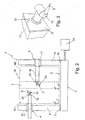
- number 1 indicates as a whole a two-arm cartesian measuring machine.
- Machine 1 substantially comprises a bed 2 defining a horizontal reference surface 3; and two horizontal-arm measuring units 4, 5 for moving respective measuring tools 6, 7 with respect to reference surface 3.
- Measuring unit 4 comprises a column 8 movable along a guide 9 extending along a longitudinal side of bed 2 and parallel to an axis X of a set of three coordinate axes X, Y, Z defining a reference system integral with bed 2.
- Guide 9 may be of any conventional type, and is only shown schematically in Figure 1 .
- Measuring unit 4 also comprises a carriage 10 fitted to and movable along column 8 along axis Z; and a horizontal arm 11 fitted to carriage 10 and movable along the horizontal axis Y.
- Measuring tool 6 is fitted to an end flange 12 of arm 11, preferably by means of a known articulated head 13, with two degrees of rotational freedom, for adjusting the position of measuring tool 6.
- measuring unit 5 comprises a column 15 movable along a guide 16 extending along the opposite longitudinal side of bed 2 to guide 9 and parallel to axis X; a carriage 17 fitted to and movable along column 15 in a direction parallel to axis Z; and a horizontal arm 18 fitted to carriage 17 and movable in a direction parallel to axis Y.
- Measuring tool 7 is fitted to an end flange 19 of arm 18, preferably by means of a known articulated head 20 with two degrees of rotational freedom.
- measuring units 4, 5 and articulated heads 13, 20 are controlled by electric motors (not shown), in turn controlled by a control and processing unit 24 connected to known linear position transducers (not shown) associated with the machine axes, and to known angular transducers (not shown) associated with articulated heads 13, 20.
- flange 12 of arm 11 of unit 4 is conveniently fitted with a reference sphere 25 for the purpose explained below.
- Each measuring unit 4, 5 has its own measuring volume defined by all the positions reachable by the measuring tool alongside variations in the position of the machine axes.
- the two measuring volumes, indicated M1 and M2 necessarily have an intersection I, and together define the measuring volume M of machine 1 when operating in "two-arm" mode.
- both arms To operate in two-arm mode, the reference systems of both arms must be aligned, i.e. the measurements of both units 4, 5 must refer to a common reference system.
- X, Y, Z reference system defined above is that of unit 4 (the primary or "master” unit)
- a s'econd x, y, z reference system may be introduced associated with unit 5 (the secondary or “slave” unit).
- Aligning the two reference systems comprises rotating and translating the reference system of slave unit 5 so that its axes are parallel to and have the same origin as those of the reference system of master unit 4.
- the movable sphere 25, integral with arm 11, is moved successively by unit 4 along a grid defined by n positions in a plane parallel to axes X and Z (i.e. a Y-constant plane) at intersection I ( Figure 4 ), e.g. is moved into nine positions arranged in three horizontal rows (and so defining respective Z- and Y-constant lines r1, r2, r3 - Figure 5 ).
- the coordinates Pi of the centre of sphere 25 in the slave system are acquired in each of the above positions, and the operation is performed for all the positions in an automatic measuring cycle defined by blocks 31 to 35 in the Figure 4 chart.
- the unit vector of direction Y may be calculated as perpendicular to the calculated plane.
- the three rows of Z-constant points provide for determining the three lines best approximating them in the x,y,z system.
- the unit vector of direction X can be calculated from the direction cosines of the "mean" of said lines, the term "mean line” referring to the line defined by the mean of the angles formed by the three lines with each of the x,y,z system axes.
- the unit vector of direction Z may be determined as the vector product of the unit vectors of directions X and Y.
- the elements of vector T can be determined from (1), by measuring the fixed sphere by means of unit 4 (block 39) and unit 5 (block 40), and calculating vector T (block 41) from the sphere centre coordinates acquired in both reference systems.
- matrix R and vector T may vary over time with respect to those originally determined at the machine setup stage.
- the rotation components may be affected by variations in the geometry and the mutual position of the machine arms - normally due to temperature, or yield caused by the workpiece load.
- thermal drift causes deformation of the transducers and structural parts of the machine, in turn resulting in a shift in the points within the measuring volume.
- the amount of shift depends not only on the amount of thermal stress applied, but also on the location of the point considered within the measuring volume. Such deformation produces variations in both matrix R and vector T.
- this may produce significant variations in pitch and roll, possibly differing from arm to the other, depending on the more or less symmetrical position of the workpiece with respect to the arms.
- a further calibration step is required, prior to release of the machine to the user, and which comprises determining the position of sphere 25 with respect to arm 11 (e.g. with respect to the flange centre). This is done by positioning sphere 25 at a point at intersection I of measuring volumes M1 and M2, where it can be detected by unit 5; and the coordinates reached by unit 4 are memorized.
- Sphere 25 is then measured by measuring tool 7 of unit 5, and the coordinates of the centre of movable sphere 25 with respect to arm 11 of unit 4 are calculated and memorized, thus giving the position of the centre of sphere 25 on the basis of the machine coordinates of unit 4.
- the above calibration step concludes setup of the machine.
- the reference system alignment updating procedures described below can be performed by the user, do not require skilled personnel as in the case of the above procedures, and, above all, do not involve prolonged, high-cost downtime of the machine.
- Alignment may be updated either fully (vector T and matrix R ) or partially, i.e. translational components only.
- Full updating is recommended in the event of a significant change in the weight of the workpiece, or at the first shift of the week, or in the event of significant variations in ambient temperature, and is a probable once-weekly procedure.
- Partial updating is recommended in the event of violent collision between the measuring tool and workpiece, whenever the measuring tool stylus is changed for one of the same type, or in the event of mild variations in ambient temperature, and is a probable once-daily procedure.
- An automatic measuring cycle (blocks 43-47) is activated to measure movable sphere 25 on unit 4 in k number of discrete positions at intersection I by means of unit 5.
- the number of positions may be defined by the user, depending on the type of workpiece.
- Block 49 calculates the angular alignment error Er in one or more predetermined directions. If angular alignment errors below a first threshold are detected, units 4 and 5 are considered still properly aligned, and the updating procedure is postponed (block 50).
- measuring tool 7 of unit 5 is assumed no longer qualified, so the updating procedure is interrupted to requalify measuring tool 7 (block 53).
- alignment is updated (block 52) by a procedure similar to the initial alignment procedure (movable sphere 25 is moved by unit 4 along a grid of points in a Y-constant plane and is measured by unit 5; the unit vector defining direction Y is calculated as perpendicular to the plane approximating the acquired points; the unit vector of direction X is calculated from the lines interpolating successions of Z-constant points; and the unit vector of direction Z is calculated as the vector product of the unit vectors defining directions X and Y).
- a residual rotation matrix R' is thus calculated, and which is used to correct the memorized rotation matrix R (the new rotation matrix equals the residual rotation matrix multiplied by the memorized rotation matrix).
- the movable sphere (25) is positioned by unit 4 in one position at intersection I (block 56) and measured by unit 5 (block 58); the sphere centre coordinates are calculated (block 60); and the translation error Et is calculated (block 61) as the difference between the sphere centre coordinates calculated on the basis of the unit 5 measurements, and the sphere centre coordinates calculated on the basis of the position coordinates of unit 4.
- a translation error is detected below (in absolute value or with reference to each individual component) a first threshold S3 (block 62), units 4 and 5 are considered still properly aligned, and the updating procedure is postponed.
- measuring tool 7 of unit 5 is assumed no longer qualified, so the updating procedure is interrupted to requalify measuring tool 7 (block 65).
- a vector T' is calculated as the difference between the sphere centre coordinates measured by unit 5 and those resulting from the coordinates of unit 4, and is used to correct the memorized vector T (block 64). That is, the new (corrected) vector T equals the sum of vector T' and the memorized translation vector.
- alignment of the reference systems of units 4 and 5 can be user-updated frequently, whenever called for by operating condition-affecting events (collision, variations in ambient temperature, changing from one workpiece to another, etc.).
- the updating procedure itself is fast, and involves no floor-mounted artifacts.
- the method ensures a high degree of measuring precision of the machine alongside variations in ambient conditions, with no need for skilled labour, and with no prolonged downtime of the machine.
- the bed and/or foundation may be made lighter with no change in precision.
- the machine may be used above-ground, in which case, the foundation obviously cannot be overly rigid for reasons of structural resistance of the building.
- the machine may comprise more than two units, and the units may be non-cartesian.
- the updating procedure may be performed using different measuring tools, such as non-contact sensors.
- the initial alignment procedure may be performed in any other known manner, e.g. by setting the fixed sphere successively to various positions at intersection I of measuring volumes M1 and M2 of units 4 and 5, and determining the sphere centre coordinates in the various positions by means of both units 4 and 5.
- a complex artifact comprising, for example, a number of spheres in predetermined relative positions.
Landscapes
- Engineering & Computer Science (AREA)
- Physics & Mathematics (AREA)
- General Physics & Mathematics (AREA)
- Robotics (AREA)
- Mechanical Engineering (AREA)
- A Measuring Device Byusing Mechanical Method (AREA)
- Length Measuring Devices With Unspecified Measuring Means (AREA)
Claims (8)
- Verfahren zum Ausrichten von Armreferenzsystemen einer Mehrarm-Messmaschine (1), umfassend wenigstens zwei Messeinheiten (4, 5), wobei jede einen beweglichen Arm (11, 18) und ein Messwerkzeug (6, 7) aufweist, das durch den Arm (11, 18) in einem jeweiligen Messvolumen (M1, M2) beweglich ist; wobei die Messvolumina (M1, M2) der Messeinheiten (4, 5) eine Überschneidung (I) aufweisen und insgesamt ein Maschinenmessvolumen (M) definieren, das gleich den kombinierten Messvolumina (M1, M2) der einzelnen Messeinheiten ist; und wobei das Verfahren die folgenden Schritte umfasst:Befestigen von wenigstens einem Referenzelement (25) an dem Arm (11) von wenigstens einer ersten der Messeinheiten (4) ;Qualifizieren von jedem der Messwerkzeuge (6, 7) der jeweiligen Messeinheiten (4, 5);Ausrichten der Referenzsysteme (X, Y, Z; x, y, z) der Messeinheiten beim Installieren der Maschine (1); undperiodisches Aktualisieren der Ausrichtung der Referenzsysteme, indem das Referenzelement (25) durch wenigstens eine andere der Messeinheiten (5) erkannt wird; wobei das Referenzelement (25) durch die erste Messeinheit (4) in eine Anzahl von Positionen in der Überschneidung (I) bewegt wird.
- Verfahren nach Anspruch 1, dadurch gekennzeichnet, dass das Referenzelement (25) am dem Arm (11) der ersten Messeinheit (4) starr befestigt ist.
- Verfahren nach Anspruch 2, dadurch gekennzeichnet, dass das Referenzelement (25) eine Kugel ist.
- Verfahren nach einem der vorhergehenden Ansprüche, dadurch gekennzeichnet, dass es den Schritt des Bestimmens der Position des Referenzelements (25) in Bezug auf den Arm (11) der ersten der Messeinheiten (4) durch die andere der Messeinheiten (5) umfasst.
- Verfahren nach einem der vorhergehenden Ansprüche, dadurch gekennzeichnet, dass der Schritt des Aktualisierens der Ausrichtung der Referenzsysteme das Aktualisieren einer Rotationsmatrix (R) und eines Translationsvektors (T) umfasst.
- Verfahren nach einem der Ansprüche 1 bis 4, dadurch gekennzeichnet, dass der Schritt des Aktualisierens der Referenzsysteme nur das Aktualisieren eines Translationsvektors (T) umfasst.
- Verfahren nach einem der vorhergehenden Ansprüche, dadurch gekennzeichnet, dass der Aktualisierungsschritt die Ausführung eines automatischen Messzyklus umfasst, in dem das Referenzelement (25) durch die erste der Messeinheiten (4) in der Überschneidung (I) positioniert wird und durch die andere der Messeinheiten (5) gemessen wird.
- Verfahren nach einem der vorhergehenden Ansprüche, dadurch gekennzeichnet, dass der Aktualisierungsschritt gestartet wird, wenn ein Restfehler festgestellt wird, der sich zwischen einem Mindest-Schwellenwert (S1; S3) und einem Maximal-Schwellenwert (S2; S4) befindet.
Priority Applications (1)
| Application Number | Priority Date | Filing Date | Title |
|---|---|---|---|
| PL07827693T PL2188586T3 (pl) | 2007-09-14 | 2007-09-14 | Sposób dostosowania układów odniesienia ramion wieloramiennego urządzenia pomiarowego |
Applications Claiming Priority (1)
| Application Number | Priority Date | Filing Date | Title |
|---|---|---|---|
| PCT/IT2007/000641 WO2009034593A1 (en) | 2007-09-14 | 2007-09-14 | Method of aligning arm reference systems of a multiple- arm measuring machine |
Publications (2)
| Publication Number | Publication Date |
|---|---|
| EP2188586A1 EP2188586A1 (de) | 2010-05-26 |
| EP2188586B1 true EP2188586B1 (de) | 2014-05-07 |
Family
ID=39365640
Family Applications (1)
| Application Number | Title | Priority Date | Filing Date |
|---|---|---|---|
| EP07827693.8A Active EP2188586B1 (de) | 2007-09-14 | 2007-09-14 | Verfahren zum ausrichten von armreferenzsystemen einer mehrarm-messmaschine |
Country Status (7)
| Country | Link |
|---|---|
| US (1) | US8166664B2 (de) |
| EP (1) | EP2188586B1 (de) |
| CN (1) | CN101861510B (de) |
| BR (1) | BRPI0722015B1 (de) |
| ES (1) | ES2475941T3 (de) |
| PL (1) | PL2188586T3 (de) |
| WO (1) | WO2009034593A1 (de) |
Cited By (2)
| Publication number | Priority date | Publication date | Assignee | Title |
|---|---|---|---|---|
| CN108349080A (zh) * | 2015-11-10 | 2018-07-31 | 库卡德国有限公司 | 校正具有输送装置和至少一个机器人的系统 |
| US10274299B2 (en) * | 2014-03-24 | 2019-04-30 | Marposs Corporation | Apparatus for inspecting machined bores |
Families Citing this family (35)
| Publication number | Priority date | Publication date | Assignee | Title |
|---|---|---|---|---|
| US9551575B2 (en) | 2009-03-25 | 2017-01-24 | Faro Technologies, Inc. | Laser scanner having a multi-color light source and real-time color receiver |
| DE102009015920B4 (de) | 2009-03-25 | 2014-11-20 | Faro Technologies, Inc. | Vorrichtung zum optischen Abtasten und Vermessen einer Umgebung |
| DE102009057101A1 (de) | 2009-11-20 | 2011-05-26 | Faro Technologies, Inc., Lake Mary | Vorrichtung zum optischen Abtasten und Vermessen einer Umgebung |
| US9210288B2 (en) | 2009-11-20 | 2015-12-08 | Faro Technologies, Inc. | Three-dimensional scanner with dichroic beam splitters to capture a variety of signals |
| US9113023B2 (en) | 2009-11-20 | 2015-08-18 | Faro Technologies, Inc. | Three-dimensional scanner with spectroscopic energy detector |
| US9529083B2 (en) | 2009-11-20 | 2016-12-27 | Faro Technologies, Inc. | Three-dimensional scanner with enhanced spectroscopic energy detector |
| US8630314B2 (en) | 2010-01-11 | 2014-01-14 | Faro Technologies, Inc. | Method and apparatus for synchronizing measurements taken by multiple metrology devices |
| US9628775B2 (en) | 2010-01-20 | 2017-04-18 | Faro Technologies, Inc. | Articulated arm coordinate measurement machine having a 2D camera and method of obtaining 3D representations |
| US9879976B2 (en) | 2010-01-20 | 2018-01-30 | Faro Technologies, Inc. | Articulated arm coordinate measurement machine that uses a 2D camera to determine 3D coordinates of smoothly continuous edge features |
| CN102782442A (zh) | 2010-01-20 | 2012-11-14 | 法罗技术股份有限公司 | 具有被照亮的探针端的坐标测量机及操作方法 |
| US8615893B2 (en) | 2010-01-20 | 2013-12-31 | Faro Technologies, Inc. | Portable articulated arm coordinate measuring machine having integrated software controls |
| US9163922B2 (en) | 2010-01-20 | 2015-10-20 | Faro Technologies, Inc. | Coordinate measurement machine with distance meter and camera to determine dimensions within camera images |
| US9607239B2 (en) | 2010-01-20 | 2017-03-28 | Faro Technologies, Inc. | Articulated arm coordinate measurement machine having a 2D camera and method of obtaining 3D representations |
| US8898919B2 (en) | 2010-01-20 | 2014-12-02 | Faro Technologies, Inc. | Coordinate measurement machine with distance meter used to establish frame of reference |
| US8875409B2 (en) | 2010-01-20 | 2014-11-04 | Faro Technologies, Inc. | Coordinate measurement machines with removable accessories |
| GB2515693B (en) | 2010-01-20 | 2015-02-11 | Faro Tech Inc | Coordinate measurement machines with removable accessories |
| CN102713498B (zh) | 2010-01-20 | 2014-07-16 | 法罗技术股份有限公司 | 用于坐标测量机的安装装置 |
| US8832954B2 (en) | 2010-01-20 | 2014-09-16 | Faro Technologies, Inc. | Coordinate measurement machines with removable accessories |
| US8677643B2 (en) | 2010-01-20 | 2014-03-25 | Faro Technologies, Inc. | Coordinate measurement machines with removable accessories |
| DE102010020925B4 (de) | 2010-05-10 | 2014-02-27 | Faro Technologies, Inc. | Verfahren zum optischen Abtasten und Vermessen einer Umgebung |
| WO2012033892A1 (en) | 2010-09-08 | 2012-03-15 | Faro Technologies, Inc. | A laser scanner or laser tracker having a projector |
| US9168654B2 (en) | 2010-11-16 | 2015-10-27 | Faro Technologies, Inc. | Coordinate measuring machines with dual layer arm |
| KR102050895B1 (ko) * | 2011-09-28 | 2020-01-08 | 유니버셜 로보츠 에이/에스 | 로봇의 캘리브레이션 및 프로그래밍 |
| DE102012100609A1 (de) | 2012-01-25 | 2013-07-25 | Faro Technologies, Inc. | Vorrichtung zum optischen Abtasten und Vermessen einer Umgebung |
| US9784554B2 (en) * | 2012-03-20 | 2017-10-10 | Hurco Companies, Inc. | Method for measuring a rotary axis of a machine tool system |
| GB201503490D0 (en) * | 2015-03-02 | 2015-04-15 | Renishaw Plc | Calibration of dimensional measuring apparatus |
| US8997362B2 (en) | 2012-07-17 | 2015-04-07 | Faro Technologies, Inc. | Portable articulated arm coordinate measuring machine with optical communications bus |
| US9513107B2 (en) | 2012-10-05 | 2016-12-06 | Faro Technologies, Inc. | Registration calculation between three-dimensional (3D) scans based on two-dimensional (2D) scan data from a 3D scanner |
| US10067231B2 (en) | 2012-10-05 | 2018-09-04 | Faro Technologies, Inc. | Registration calculation of three-dimensional scanner data performed between scans based on measurements by two-dimensional scanner |
| DE102012109481A1 (de) | 2012-10-05 | 2014-04-10 | Faro Technologies, Inc. | Vorrichtung zum optischen Abtasten und Vermessen einer Umgebung |
| JP6157953B2 (ja) * | 2013-06-27 | 2017-07-05 | 株式会社ミツトヨ | 三次元形状測定システム及びその制御用ソフトウェア |
| JP6368083B2 (ja) * | 2013-11-27 | 2018-08-01 | 株式会社ミツトヨ | 精密測定装置 |
| TWI557522B (zh) * | 2015-11-05 | 2016-11-11 | 財團法人工業技術研究院 | 校正方法與校正設備 |
| DE102015122844A1 (de) | 2015-12-27 | 2017-06-29 | Faro Technologies, Inc. | 3D-Messvorrichtung mit Batteriepack |
| CN111272068B (zh) * | 2020-02-24 | 2021-07-27 | 重庆市计量质量检测研究院 | 协作多臂测量系统的联合误差评价、检测方法与系统 |
Family Cites Families (10)
| Publication number | Priority date | Publication date | Assignee | Title |
|---|---|---|---|---|
| US4326338A (en) * | 1980-09-10 | 1982-04-27 | The L.S. Starrett Company | Area comparison gage |
| FR2617589B1 (fr) * | 1987-06-30 | 1989-12-08 | Inst Francais Du Petrole | Dispositif et methode de mesure des deformations d'un echantillon |
| US5193286A (en) * | 1992-04-21 | 1993-03-16 | Collier Kevin E | Modular gage |
| FR2710407B1 (fr) | 1993-09-20 | 1995-12-01 | Romer Srl | Procédé de repérage positionnel pour une machine de mesure tridimensionnelle et dispositif pour la mise en Óoeuvre du procédé. |
| JP3905771B2 (ja) * | 2001-03-02 | 2007-04-18 | 株式会社ミツトヨ | 測定機の校正方法及び装置 |
| US7010390B2 (en) * | 2003-07-17 | 2006-03-07 | Kuka Roboter Gmbh | Method and system for controlling robots |
| JP3946711B2 (ja) * | 2004-06-02 | 2007-07-18 | ファナック株式会社 | ロボットシステム |
| CN101358830B (zh) * | 2007-08-03 | 2012-01-25 | 鸿富锦精密工业(深圳)有限公司 | 测量设备 |
| US7640674B2 (en) * | 2008-05-05 | 2010-01-05 | Hexagon Metrology, Inc. | Systems and methods for calibrating a portable coordinate measurement machine |
| US7752003B2 (en) * | 2008-06-27 | 2010-07-06 | Hexagon Metrology, Inc. | Hysteresis compensation in a coordinate measurement machine |
-
2007
- 2007-09-14 ES ES07827693.8T patent/ES2475941T3/es active Active
- 2007-09-14 WO PCT/IT2007/000641 patent/WO2009034593A1/en active Application Filing
- 2007-09-14 US US12/678,154 patent/US8166664B2/en active Active
- 2007-09-14 EP EP07827693.8A patent/EP2188586B1/de active Active
- 2007-09-14 CN CN200780101560.4A patent/CN101861510B/zh not_active Expired - Fee Related
- 2007-09-14 BR BRPI0722015-4A patent/BRPI0722015B1/pt not_active IP Right Cessation
- 2007-09-14 PL PL07827693T patent/PL2188586T3/pl unknown
Non-Patent Citations (2)
| Title |
|---|
| "CARB Series, Non-contact/contact horizontal-arm type CNC Coordinate Measuring Machines for the car body industry", CATALOG NO. E4322-360, pages 1 - 32, XP055029671, Retrieved from the Internet <URL:http://www.mitutoyo.co.jp/eng/support/service/catalog/01/E4322_360.pdf> [retrieved on 20120612] * |
| "Coordinate Measuring Machines, The Best Solution for 3-D Metrology", BULLETIN 1745, 1 May 2004 (2004-05-01), pages 1 - 8, XP055029667, Retrieved from the Internet <URL:http://www.mitutoyo.com/pdf/3C-6.pdf> [retrieved on 20120612] * |
Cited By (4)
| Publication number | Priority date | Publication date | Assignee | Title |
|---|---|---|---|---|
| US10274299B2 (en) * | 2014-03-24 | 2019-04-30 | Marposs Corporation | Apparatus for inspecting machined bores |
| CN108349080A (zh) * | 2015-11-10 | 2018-07-31 | 库卡德国有限公司 | 校正具有输送装置和至少一个机器人的系统 |
| US10940590B2 (en) | 2015-11-10 | 2021-03-09 | Kuka Deutschland Gmbh | Calibrating a system with a conveying means and at least one robot |
| CN108349080B (zh) * | 2015-11-10 | 2022-03-15 | 库卡德国有限公司 | 校正具有输送装置和至少一个机器人的系统 |
Also Published As
| Publication number | Publication date |
|---|---|
| EP2188586A1 (de) | 2010-05-26 |
| BRPI0722015B1 (pt) | 2018-04-10 |
| CN101861510B (zh) | 2014-05-14 |
| US20100281705A1 (en) | 2010-11-11 |
| WO2009034593A1 (en) | 2009-03-19 |
| PL2188586T3 (pl) | 2014-09-30 |
| CN101861510A (zh) | 2010-10-13 |
| ES2475941T3 (es) | 2014-07-11 |
| US8166664B2 (en) | 2012-05-01 |
| BRPI0722015A2 (pt) | 2015-10-13 |
Similar Documents
| Publication | Publication Date | Title |
|---|---|---|
| EP2188586B1 (de) | Verfahren zum ausrichten von armreferenzsystemen einer mehrarm-messmaschine | |
| Jiang et al. | A method of testing position independent geometric errors in rotary axes of a five-axis machine tool using a double ball bar | |
| CN108151660B (zh) | 一种飞机部件对接间隙和阶差的测量装备、方法及系统 | |
| CN102458779B (zh) | 机械手校正装置及其方法 | |
| US6681145B1 (en) | Method for improving the accuracy of machines | |
| EP1579168B2 (de) | Werkstückinspektionsverfahren und vorrichtung | |
| US5949685A (en) | Real-time orientation of machine media to improve machine accuracy | |
| JP4660779B2 (ja) | 移動装置の位置誤差評価方法およびその評価結果に基づく移動精度向上方法 | |
| US5903459A (en) | Method for product acceptance by improving the accuracy of machines | |
| US8401692B2 (en) | System and method for tool testing and alignment | |
| US20110178782A1 (en) | Method for Estimating Geometric Error Between Linear Axis and Rotary Axis in a Multi-Axis Machine Tool | |
| EP0042960A1 (de) | Verfahren und Vorrichtung zum Kalibrieren eines Roboters | |
| EP3339801B1 (de) | Selbstüberwachendes herstellungssystem, produktionsüberwachungseinheit und verwendung der produktionsüberwachungseinheit | |
| US20140130571A1 (en) | System and method for offsetting measurement of machine tool | |
| CN101802548B (zh) | 补偿测量机器的测量误差的方法和使用该方法的测量机器 | |
| US11892820B2 (en) | Error compensation method for machine tool and machine tool | |
| EP0223862A1 (de) | Vorrichtung zum einstellen eines roboters in eine referenzlage | |
| US10315255B2 (en) | Machine tool with an assembly configuration with a cantilevered tool | |
| JP2983941B2 (ja) | 3次元自動計測装置用計測誤差補正方法 | |
| CN106873644B (zh) | 一种对飞行器地面仿真系统平动机构高精度姿态控制方法 | |
| JPH10301609A (ja) | ロボットの位置誤差検出方法及びその装置 | |
| JP2007509332A (ja) | 複雑な表面輪郭を有する部材の超音波検査のための方法及び装置 | |
| JPH11114777A (ja) | 工作機械の制御方法 | |
| JPH0516888A (ja) | 航空機胴体外板の穴あけ方法 | |
| EP3101384B1 (de) | Kalibrierungsverfahren zur kalibrierung der antriebsachse einer werkzeugmaschine |
Legal Events
| Date | Code | Title | Description |
|---|---|---|---|
| PUAI | Public reference made under article 153(3) epc to a published international application that has entered the european phase |
Free format text: ORIGINAL CODE: 0009012 |
|
| 17P | Request for examination filed |
Effective date: 20100311 |
|
| AK | Designated contracting states |
Kind code of ref document: A1 Designated state(s): AT BE BG CH CY CZ DE DK EE ES FI FR GB GR HU IE IS IT LI LT LU LV MC MT NL PL PT RO SE SI SK TR |
|
| AX | Request for extension of the european patent |
Extension state: AL BA HR MK RS |
|
| DAX | Request for extension of the european patent (deleted) | ||
| 17Q | First examination report despatched |
Effective date: 20120622 |
|
| GRAP | Despatch of communication of intention to grant a patent |
Free format text: ORIGINAL CODE: EPIDOSNIGR1 |
|
| INTG | Intention to grant announced |
Effective date: 20131126 |
|
| GRAS | Grant fee paid |
Free format text: ORIGINAL CODE: EPIDOSNIGR3 |
|
| GRAA | (expected) grant |
Free format text: ORIGINAL CODE: 0009210 |
|
| AK | Designated contracting states |
Kind code of ref document: B1 Designated state(s): AT BE BG CH CY CZ DE DK EE ES FI FR GB GR HU IE IS IT LI LT LU LV MC MT NL PL PT RO SE SI SK TR |
|
| REG | Reference to a national code |
Ref country code: GB Ref legal event code: FG4D |
|
| REG | Reference to a national code |
Ref country code: AT Ref legal event code: REF Ref document number: 667018 Country of ref document: AT Kind code of ref document: T Effective date: 20140515 |
|
| REG | Reference to a national code |
Ref country code: IE Ref legal event code: FG4D |
|
| REG | Reference to a national code |
Ref country code: DE Ref legal event code: R096 Ref document number: 602007036591 Country of ref document: DE Effective date: 20140618 |
|
| REG | Reference to a national code |
Ref country code: ES Ref legal event code: FG2A Ref document number: 2475941 Country of ref document: ES Kind code of ref document: T3 Effective date: 20140711 |
|
| REG | Reference to a national code |
Ref country code: CH Ref legal event code: NV Representative=s name: KAMINSKI HARMANN PATENTANWAELTE AG, LI |
|
| REG | Reference to a national code |
Ref country code: AT Ref legal event code: MK05 Ref document number: 667018 Country of ref document: AT Kind code of ref document: T Effective date: 20140507 |
|
| REG | Reference to a national code |
Ref country code: PL Ref legal event code: T3 |
|
| REG | Reference to a national code |
Ref country code: NL Ref legal event code: VDEP Effective date: 20140507 |
|
| REG | Reference to a national code |
Ref country code: LT Ref legal event code: MG4D |
|
| PG25 | Lapsed in a contracting state [announced via postgrant information from national office to epo] |
Ref country code: LT Free format text: LAPSE BECAUSE OF FAILURE TO SUBMIT A TRANSLATION OF THE DESCRIPTION OR TO PAY THE FEE WITHIN THE PRESCRIBED TIME-LIMIT Effective date: 20140507 Ref country code: FI Free format text: LAPSE BECAUSE OF FAILURE TO SUBMIT A TRANSLATION OF THE DESCRIPTION OR TO PAY THE FEE WITHIN THE PRESCRIBED TIME-LIMIT Effective date: 20140507 Ref country code: CY Free format text: LAPSE BECAUSE OF FAILURE TO SUBMIT A TRANSLATION OF THE DESCRIPTION OR TO PAY THE FEE WITHIN THE PRESCRIBED TIME-LIMIT Effective date: 20140507 Ref country code: IS Free format text: LAPSE BECAUSE OF FAILURE TO SUBMIT A TRANSLATION OF THE DESCRIPTION OR TO PAY THE FEE WITHIN THE PRESCRIBED TIME-LIMIT Effective date: 20140907 Ref country code: GR Free format text: LAPSE BECAUSE OF FAILURE TO SUBMIT A TRANSLATION OF THE DESCRIPTION OR TO PAY THE FEE WITHIN THE PRESCRIBED TIME-LIMIT Effective date: 20140808 |
|
| PG25 | Lapsed in a contracting state [announced via postgrant information from national office to epo] |
Ref country code: SE Free format text: LAPSE BECAUSE OF FAILURE TO SUBMIT A TRANSLATION OF THE DESCRIPTION OR TO PAY THE FEE WITHIN THE PRESCRIBED TIME-LIMIT Effective date: 20140507 Ref country code: LV Free format text: LAPSE BECAUSE OF FAILURE TO SUBMIT A TRANSLATION OF THE DESCRIPTION OR TO PAY THE FEE WITHIN THE PRESCRIBED TIME-LIMIT Effective date: 20140507 Ref country code: AT Free format text: LAPSE BECAUSE OF FAILURE TO SUBMIT A TRANSLATION OF THE DESCRIPTION OR TO PAY THE FEE WITHIN THE PRESCRIBED TIME-LIMIT Effective date: 20140507 |
|
| PG25 | Lapsed in a contracting state [announced via postgrant information from national office to epo] |
Ref country code: PT Free format text: LAPSE BECAUSE OF FAILURE TO SUBMIT A TRANSLATION OF THE DESCRIPTION OR TO PAY THE FEE WITHIN THE PRESCRIBED TIME-LIMIT Effective date: 20140908 |
|
| PG25 | Lapsed in a contracting state [announced via postgrant information from national office to epo] |
Ref country code: BE Free format text: LAPSE BECAUSE OF FAILURE TO SUBMIT A TRANSLATION OF THE DESCRIPTION OR TO PAY THE FEE WITHIN THE PRESCRIBED TIME-LIMIT Effective date: 20140507 Ref country code: CZ Free format text: LAPSE BECAUSE OF FAILURE TO SUBMIT A TRANSLATION OF THE DESCRIPTION OR TO PAY THE FEE WITHIN THE PRESCRIBED TIME-LIMIT Effective date: 20140507 Ref country code: RO Free format text: LAPSE BECAUSE OF FAILURE TO SUBMIT A TRANSLATION OF THE DESCRIPTION OR TO PAY THE FEE WITHIN THE PRESCRIBED TIME-LIMIT Effective date: 20140507 Ref country code: EE Free format text: LAPSE BECAUSE OF FAILURE TO SUBMIT A TRANSLATION OF THE DESCRIPTION OR TO PAY THE FEE WITHIN THE PRESCRIBED TIME-LIMIT Effective date: 20140507 Ref country code: SK Free format text: LAPSE BECAUSE OF FAILURE TO SUBMIT A TRANSLATION OF THE DESCRIPTION OR TO PAY THE FEE WITHIN THE PRESCRIBED TIME-LIMIT Effective date: 20140507 Ref country code: DK Free format text: LAPSE BECAUSE OF FAILURE TO SUBMIT A TRANSLATION OF THE DESCRIPTION OR TO PAY THE FEE WITHIN THE PRESCRIBED TIME-LIMIT Effective date: 20140507 |
|
| REG | Reference to a national code |
Ref country code: DE Ref legal event code: R097 Ref document number: 602007036591 Country of ref document: DE |
|
| PG25 | Lapsed in a contracting state [announced via postgrant information from national office to epo] |
Ref country code: NL Free format text: LAPSE BECAUSE OF FAILURE TO SUBMIT A TRANSLATION OF THE DESCRIPTION OR TO PAY THE FEE WITHIN THE PRESCRIBED TIME-LIMIT Effective date: 20140507 |
|
| PLBE | No opposition filed within time limit |
Free format text: ORIGINAL CODE: 0009261 |
|
| STAA | Information on the status of an ep patent application or granted ep patent |
Free format text: STATUS: NO OPPOSITION FILED WITHIN TIME LIMIT |
|
| 26N | No opposition filed |
Effective date: 20150210 |
|
| PG25 | Lapsed in a contracting state [announced via postgrant information from national office to epo] |
Ref country code: MC Free format text: LAPSE BECAUSE OF FAILURE TO SUBMIT A TRANSLATION OF THE DESCRIPTION OR TO PAY THE FEE WITHIN THE PRESCRIBED TIME-LIMIT Effective date: 20140507 Ref country code: LU Free format text: LAPSE BECAUSE OF FAILURE TO SUBMIT A TRANSLATION OF THE DESCRIPTION OR TO PAY THE FEE WITHIN THE PRESCRIBED TIME-LIMIT Effective date: 20140914 |
|
| REG | Reference to a national code |
Ref country code: DE Ref legal event code: R097 Ref document number: 602007036591 Country of ref document: DE Effective date: 20150210 |
|
| REG | Reference to a national code |
Ref country code: IE Ref legal event code: MM4A |
|
| PG25 | Lapsed in a contracting state [announced via postgrant information from national office to epo] |
Ref country code: SI Free format text: LAPSE BECAUSE OF FAILURE TO SUBMIT A TRANSLATION OF THE DESCRIPTION OR TO PAY THE FEE WITHIN THE PRESCRIBED TIME-LIMIT Effective date: 20140507 |
|
| PG25 | Lapsed in a contracting state [announced via postgrant information from national office to epo] |
Ref country code: IE Free format text: LAPSE BECAUSE OF NON-PAYMENT OF DUE FEES Effective date: 20140914 |
|
| PG25 | Lapsed in a contracting state [announced via postgrant information from national office to epo] |
Ref country code: BG Free format text: LAPSE BECAUSE OF FAILURE TO SUBMIT A TRANSLATION OF THE DESCRIPTION OR TO PAY THE FEE WITHIN THE PRESCRIBED TIME-LIMIT Effective date: 20140507 |
|
| PG25 | Lapsed in a contracting state [announced via postgrant information from national office to epo] |
Ref country code: MT Free format text: LAPSE BECAUSE OF FAILURE TO SUBMIT A TRANSLATION OF THE DESCRIPTION OR TO PAY THE FEE WITHIN THE PRESCRIBED TIME-LIMIT Effective date: 20140507 |
|
| PG25 | Lapsed in a contracting state [announced via postgrant information from national office to epo] |
Ref country code: TR Free format text: LAPSE BECAUSE OF FAILURE TO SUBMIT A TRANSLATION OF THE DESCRIPTION OR TO PAY THE FEE WITHIN THE PRESCRIBED TIME-LIMIT Effective date: 20140507 Ref country code: HU Free format text: LAPSE BECAUSE OF FAILURE TO SUBMIT A TRANSLATION OF THE DESCRIPTION OR TO PAY THE FEE WITHIN THE PRESCRIBED TIME-LIMIT; INVALID AB INITIO Effective date: 20070914 |
|
| REG | Reference to a national code |
Ref country code: FR Ref legal event code: PLFP Year of fee payment: 10 |
|
| REG | Reference to a national code |
Ref country code: FR Ref legal event code: PLFP Year of fee payment: 11 |
|
| REG | Reference to a national code |
Ref country code: FR Ref legal event code: PLFP Year of fee payment: 12 |
|
| PGFP | Annual fee paid to national office [announced via postgrant information from national office to epo] |
Ref country code: FR Payment date: 20190926 Year of fee payment: 13 |
|
| PGFP | Annual fee paid to national office [announced via postgrant information from national office to epo] |
Ref country code: PL Payment date: 20190903 Year of fee payment: 13 |
|
| PGFP | Annual fee paid to national office [announced via postgrant information from national office to epo] |
Ref country code: GB Payment date: 20190930 Year of fee payment: 13 |
|
| PGFP | Annual fee paid to national office [announced via postgrant information from national office to epo] |
Ref country code: CH Payment date: 20190925 Year of fee payment: 13 |
|
| PGFP | Annual fee paid to national office [announced via postgrant information from national office to epo] |
Ref country code: ES Payment date: 20191021 Year of fee payment: 13 |
|
| REG | Reference to a national code |
Ref country code: CH Ref legal event code: PL |
|
| GBPC | Gb: european patent ceased through non-payment of renewal fee |
Effective date: 20200914 |
|
| PG25 | Lapsed in a contracting state [announced via postgrant information from national office to epo] |
Ref country code: FR Free format text: LAPSE BECAUSE OF NON-PAYMENT OF DUE FEES Effective date: 20200930 |
|
| PG25 | Lapsed in a contracting state [announced via postgrant information from national office to epo] |
Ref country code: CH Free format text: LAPSE BECAUSE OF NON-PAYMENT OF DUE FEES Effective date: 20200930 Ref country code: LI Free format text: LAPSE BECAUSE OF NON-PAYMENT OF DUE FEES Effective date: 20200930 Ref country code: GB Free format text: LAPSE BECAUSE OF NON-PAYMENT OF DUE FEES Effective date: 20200914 |
|
| REG | Reference to a national code |
Ref country code: ES Ref legal event code: FD2A Effective date: 20220117 |
|
| PG25 | Lapsed in a contracting state [announced via postgrant information from national office to epo] |
Ref country code: ES Free format text: LAPSE BECAUSE OF NON-PAYMENT OF DUE FEES Effective date: 20200915 |
|
| PG25 | Lapsed in a contracting state [announced via postgrant information from national office to epo] |
Ref country code: PL Free format text: LAPSE BECAUSE OF NON-PAYMENT OF DUE FEES Effective date: 20200914 |
|
| PGFP | Annual fee paid to national office [announced via postgrant information from national office to epo] |
Ref country code: IT Payment date: 20230905 Year of fee payment: 17 |
|
| PGFP | Annual fee paid to national office [announced via postgrant information from national office to epo] |
Ref country code: DE Payment date: 20230928 Year of fee payment: 17 |