EP2188586B1 - Method of aligning arm reference systems of a multiple- arm measuring machine - Google Patents
Method of aligning arm reference systems of a multiple- arm measuring machine Download PDFInfo
- Publication number
- EP2188586B1 EP2188586B1 EP07827693.8A EP07827693A EP2188586B1 EP 2188586 B1 EP2188586 B1 EP 2188586B1 EP 07827693 A EP07827693 A EP 07827693A EP 2188586 B1 EP2188586 B1 EP 2188586B1
- Authority
- EP
- European Patent Office
- Prior art keywords
- measuring
- arm
- updating
- units
- measuring units
- Prior art date
- Legal status (The legal status is an assumption and is not a legal conclusion. Google has not performed a legal analysis and makes no representation as to the accuracy of the status listed.)
- Active
Links
- 238000000034 method Methods 0.000 title claims description 45
- 239000013598 vector Substances 0.000 claims description 27
- 239000011159 matrix material Substances 0.000 claims description 17
- 238000013519 translation Methods 0.000 claims description 9
- 238000001514 detection method Methods 0.000 claims 1
- 238000009434 installation Methods 0.000 description 2
- 238000005259 measurement Methods 0.000 description 2
- 230000002035 prolonged effect Effects 0.000 description 2
- 230000004308 accommodation Effects 0.000 description 1
- 230000000694 effects Effects 0.000 description 1
- 230000002708 enhancing effect Effects 0.000 description 1
- 230000007613 environmental effect Effects 0.000 description 1
- 230000002452 interceptive effect Effects 0.000 description 1
- 238000005457 optimization Methods 0.000 description 1
- 238000012545 processing Methods 0.000 description 1
- 238000012797 qualification Methods 0.000 description 1
- 239000000700 radioactive tracer Substances 0.000 description 1
- 238000004513 sizing Methods 0.000 description 1
- 230000008646 thermal stress Effects 0.000 description 1
- 230000009466 transformation Effects 0.000 description 1
Images


Classifications
-
- G—PHYSICS
- G01—MEASURING; TESTING
- G01B—MEASURING LENGTH, THICKNESS OR SIMILAR LINEAR DIMENSIONS; MEASURING ANGLES; MEASURING AREAS; MEASURING IRREGULARITIES OF SURFACES OR CONTOURS
- G01B21/00—Measuring arrangements or details thereof, where the measuring technique is not covered by the other groups of this subclass, unspecified or not relevant
- G01B21/02—Measuring arrangements or details thereof, where the measuring technique is not covered by the other groups of this subclass, unspecified or not relevant for measuring length, width, or thickness
- G01B21/04—Measuring arrangements or details thereof, where the measuring technique is not covered by the other groups of this subclass, unspecified or not relevant for measuring length, width, or thickness by measuring coordinates of points
- G01B21/042—Calibration or calibration artifacts
-
- B—PERFORMING OPERATIONS; TRANSPORTING
- B25—HAND TOOLS; PORTABLE POWER-DRIVEN TOOLS; MANIPULATORS
- B25J—MANIPULATORS; CHAMBERS PROVIDED WITH MANIPULATION DEVICES
- B25J9/00—Programme-controlled manipulators
- B25J9/16—Programme controls
- B25J9/1679—Programme controls characterised by the tasks executed
- B25J9/1682—Dual arm manipulator; Coordination of several manipulators
-
- B—PERFORMING OPERATIONS; TRANSPORTING
- B25—HAND TOOLS; PORTABLE POWER-DRIVEN TOOLS; MANIPULATORS
- B25J—MANIPULATORS; CHAMBERS PROVIDED WITH MANIPULATION DEVICES
- B25J9/00—Programme-controlled manipulators
- B25J9/16—Programme controls
- B25J9/1679—Programme controls characterised by the tasks executed
- B25J9/1692—Calibration of manipulator
-
- G—PHYSICS
- G01—MEASURING; TESTING
- G01B—MEASURING LENGTH, THICKNESS OR SIMILAR LINEAR DIMENSIONS; MEASURING ANGLES; MEASURING AREAS; MEASURING IRREGULARITIES OF SURFACES OR CONTOURS
- G01B5/00—Measuring arrangements characterised by the use of mechanical techniques
- G01B5/004—Measuring arrangements characterised by the use of mechanical techniques for measuring coordinates of points
- G01B5/008—Measuring arrangements characterised by the use of mechanical techniques for measuring coordinates of points using coordinate measuring machines
-
- G—PHYSICS
- G05—CONTROLLING; REGULATING
- G05B—CONTROL OR REGULATING SYSTEMS IN GENERAL; FUNCTIONAL ELEMENTS OF SUCH SYSTEMS; MONITORING OR TESTING ARRANGEMENTS FOR SUCH SYSTEMS OR ELEMENTS
- G05B2219/00—Program-control systems
- G05B2219/30—Nc systems
- G05B2219/39—Robotics, robotics to robotics hand
- G05B2219/39051—Calibration cooperating manipulators, closed kinematic chain by alignment
Landscapes
- Engineering & Computer Science (AREA)
- Physics & Mathematics (AREA)
- General Physics & Mathematics (AREA)
- Robotics (AREA)
- Mechanical Engineering (AREA)
- A Measuring Device Byusing Mechanical Method (AREA)
- Length Measuring Devices With Unspecified Measuring Means (AREA)
Description
- The present invention relates to a method of aligning arm reference systems of a multiple-arm measuring machine.
- As is known, multiple-arm measuring machines comprise two or more measuring units, each with its own measuring tool, which operate in coordination under the control of a common control system. The measuring units are normally positioned with their respective measuring volumes side by side and overlapping at a small intersection, so the overall measuring volume of the machine is defined by the combined measuring volumes of the individual units. Multiple-arm measuring machines of the above type are therefore particularly suitable for measuring large-size parts, such as vehicle bodies or aircraft components.
- In a typical embodiment, to which the following description refers for convenience and purely by way of example, the machine comprises two horizontal-arm cartesian measuring units located on opposite sides of the measuring volume, and each unit comprises a column movable along a longitudinal first axis with respect to the measuring volume, a carriage fitted to the column and movable along a vertical second axis, and an arm fitted to the carriage and movable with respect to it along a horizontal third axis perpendicular to the first axis and crosswise to the measuring volume.
- In multiple-arm machines employing coordinate measuring units (particularly machines with two horizontal arms), aligning the cartesian reference system of one of the two arms (the secondary or "slave" arm) with respect to the other (the "primary" or "master" arm) is vital to measuring performance in two-arm mode.
- The usual alignment method comprises measuring a sphere variously positioned at the intersection between the measuring volumes of the two units, and accordingly rotating and translating the cartesian reference system of the secondary arm with respect to that of the primary arm.
- Measuring machine performance in multiple-arm mode depends closely on the compensation precision and dimensional stability of the individual units, and on the precision and stability of the results of the above alignment procedure.
- The latter, in particular, is affected by deformation of both measuring units caused by variations in ambient temperature, which may result in distortion of the geometry of both units, not entirely recoverable by the geometric compensation procedure, and in elongation of the component parts of the units (transducers, beams, etc.), which often results in measuring errors serious enough to impair performance.
- Distortion of individual units also results in even serious measuring errors in multiple-arm mode.
- Frequently updating alignment of the cartesian reference systems of each unit of a multiple-arm machine is therefore of vital importance, but in actual fact difficult, if not impossible, to do in the case of online measuring systems, which rule out a fixed floor-mounted sphere for obvious accommodation reasons.
- Another factor affecting the performance of multiple-arm machines is the weight of the workpiece, which may cause significant yield of the foundation and/or bed on which the units are installed, thus affecting the no-load-determined alignment conditions of the units.
- One way of minimizing this effect is to align the systems with the workpiece set up in place, though often the very size of the workpiece prevents this. A "mockup" is another possible solution, but often unpractical and technically unfeasible, by involving additional movements, possibly interfering with dedicated workpiece supporting fixtures, and possibly differing considerably from the load configuration of the actual workpiece. The problem with this solution is further compounded by the load varying with different workpieces.
- The only solution to these problems lies in oversizing the foundation and/or bed, thus increasing the cost of the machine.
-
EP 1 607 194 - In particular, a first robot has a camera mounted thereon and a second robot has a feature portion that is moved so that the image of the feature portion detected by the camera assumes a target position or size. The same process is repeated for several times while changing the position of the initial state of the robots in order to calibrate the relative position between the robots.
- It is an object of the present invention to provide a method of aligning arm reference systems of a multiple-arm measuring machine, designed to eliminate the aforementioned drawbacks typically associated with known methods.
- According to the present invention, there is provided a method of aligning arm reference systems of a multiple-arm measuring machine, as claimed in
Claim 1. - The invention (which also applies to non-cartesian machines and to other than two-arm multiple-arm systems) provides for periodically updating the alignment matrix by means of one or more reference members located on the structure of at least one of the measuring units and measurable by the other unit.
- The reference members may be:
- a) one or more calibrated spheres located on the end of one of the arms and easily accessible by the tracer on the other arm, or, in an example not covered by the invention, located on a dedicated tool interchangeable with the measuring tools and housable in the tool-change store;
- b) dedicated gauges, if the machine is equipped with non-contact tracers only, which cannot measure the above spheres easily.
- By means of appropriate measuring programs activated automatically or by the operator alongside changes in the type of workpiece or in environmental conditions, such as variations in temperature, the invention provides for updating the alignment matrix, thus improving measuring performance and greatly reducing cost in terms of sizing of the foundation and/or bed.
- Moreover, the method may be applied to the actual workpiece-occupied portion of the local volume common to both arms, thus potentially improving measuring performance and also enhancing the versatility of the system, which can thus be used for measuring both large- and small-size workpieces (vehicle bodies and panels).
- A preferred, non-limiting embodiment of the present invention will be described by way of example with reference to the accompanying drawings, in which:
-
Figure 1 shows a schematic plan view of a two-arm measuring machine in accordance with the present invention; -
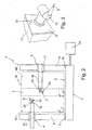
Figure 2 shows a schematic front view of theFigure 1 machine; -
Figure 3 shows a schematic detail of a measuring unit of theFigure 1 machine; -
Figure 4 shows a flow chart of a procedure for aligning the reference systems of theFigure 1 machine at the machine installation stage; -
Figure 5 shows the location of a reference member during the procedure shown in theFigure 4 flow chart; -
Figure 6 shows a flow chart of a first operation in updating alignment of the reference systems of theFigure 1 machine measuring units; -
Figure 7 shows a flow chart of a second operation in updating alignment of the reference systems of theFigure 1 machine measuring units. - With reference to
Figures 1 and2 ,number 1 indicates as a whole a two-arm cartesian measuring machine. -
Machine 1 substantially comprises abed 2 defining ahorizontal reference surface 3; and two horizontal-arm measuring units respective measuring tools reference surface 3. -
Measuring unit 4 comprises acolumn 8 movable along aguide 9 extending along a longitudinal side ofbed 2 and parallel to an axis X of a set of three coordinate axes X, Y, Z defining a reference system integral withbed 2.Guide 9 may be of any conventional type, and is only shown schematically inFigure 1 . -
Measuring unit 4 also comprises acarriage 10 fitted to and movable alongcolumn 8 along axis Z; and ahorizontal arm 11 fitted tocarriage 10 and movable along the horizontal axis Y. -
Measuring tool 6 is fitted to anend flange 12 ofarm 11, preferably by means of a known articulatedhead 13, with two degrees of rotational freedom, for adjusting the position of measuringtool 6. - Likewise, measuring
unit 5 comprises acolumn 15 movable along aguide 16 extending along the opposite longitudinal side ofbed 2 to guide 9 and parallel to axis X; acarriage 17 fitted to and movable alongcolumn 15 in a direction parallel to axis Z; and ahorizontal arm 18 fitted tocarriage 17 and movable in a direction parallel to axis Y. -
Measuring tool 7 is fitted to anend flange 19 ofarm 18, preferably by means of a known articulatedhead 20 with two degrees of rotational freedom. - The moving parts of
measuring units heads processing unit 24 connected to known linear position transducers (not shown) associated with the machine axes, and to known angular transducers (not shown) associated with articulatedheads - As shown more clearly in
Figure 3 ,flange 12 ofarm 11 ofunit 4 is conveniently fitted with areference sphere 25 for the purpose explained below. - Each
measuring unit machine 1 when operating in "two-arm" mode. - To operate in two-arm mode, the reference systems of both arms must be aligned, i.e. the measurements of both
units - Assuming the X, Y, Z reference system defined above is that of unit 4 (the primary or "master" unit), a s'econd x, y, z reference system may be introduced associated with unit 5 (the secondary or "slave" unit).
- Aligning the two reference systems comprises rotating and translating the reference system of
slave unit 5 so that its axes are parallel to and have the same origin as those of the reference system ofmaster unit 4. - Mathematically, this amounts to applying a coordinate transformation τ :

where : - P is the three-component vector (X, Y, Z) of the master system coordinates;
- p is the three-component vector (x, y, z) of the slave system coordinates;
- T is a three-component translation vector (tx, ty, tz) which determines the position of the origin of the slave coordinate system in the master coordinate system; and
- R is a rotation matrix (3 by 3).
- When setting up
machine 1, routine geometric compensation ofunits measuring tools units - A simple, easily automated method of determining rotation components only is as follows (
Figure 4 ). - The
movable sphere 25, integral witharm 11, is moved successively byunit 4 along a grid defined by n positions in a plane parallel to axes X and Z (i.e. a Y-constant plane) at intersection I (Figure 4 ), e.g. is moved into nine positions arranged in three horizontal rows (and so defining respective Z- and Y-constant lines r1, r2, r3 -Figure 5 ). The coordinates Pi of the centre ofsphere 25 in the slave system are acquired in each of the above positions, and the operation is performed for all the positions in an automatic measuring cycle defined byblocks 31 to 35 in theFigure 4 chart. - By means of an optimization, e.g. least squares, method, it is therefore possible to calculate the plane which best approximates the 9 points in the x,y,z slave reference system (block 36), and calculate the directions of axes X,Y,Z in the slave system (block 37).
- More specifically, the unit vector of direction Y may be calculated as perpendicular to the calculated plane. The three rows of Z-constant points provide for determining the three lines best approximating them in the x,y,z system. The unit vector of direction X can be calculated from the direction cosines of the "mean" of said lines, the term "mean line" referring to the line defined by the mean of the angles formed by the three lines with each of the x,y,z system axes.
- Finally, the unit vector of direction Z may be determined as the vector product of the unit vectors of directions X and Y.
- By the end of the procedure, the direction cosines of axes X, Y, Z in the x,y,z system and hence the components of matrix R are therefore known (block 38).
- Given the coordinates in both coordinate systems of a specific point in the measuring volume, and given matrix R, the elements of vector T can be determined from (1), by measuring the fixed sphere by means of unit 4 (block 39) and unit 5 (block 40), and calculating vector T (block 41) from the sphere centre coordinates acquired in both reference systems.
- By the end of this procedure, which is performed as part of post-installation setup of the machine, alignment of the reference systems may be considered complete.
- In actual fact, however, the components of matrix R and vector T may vary over time with respect to those originally determined at the machine setup stage.
- The rotation components may be affected by variations in the geometry and the mutual position of the machine arms - normally due to temperature, or yield caused by the workpiece load.
- Foremost of the thermal factors affecting performance of multiple-arm machines is what is known as thermal drift, which causes deformation of the transducers and structural parts of the machine, in turn resulting in a shift in the points within the measuring volume. The amount of shift depends not only on the amount of thermal stress applied, but also on the location of the point considered within the measuring volume. Such deformation produces variations in both matrix R and vector T.
- As regards the workpiece load, this may produce significant variations in pitch and roll, possibly differing from arm to the other, depending on the more or less symmetrical position of the workpiece with respect to the arms.
- To periodically update matrix R and vector T, a further calibration step is required, prior to release of the machine to the user, and which comprises determining the position of
sphere 25 with respect to arm 11 (e.g. with respect to the flange centre). This is done by positioningsphere 25 at a point at intersection I of measuring volumes M1 and M2, where it can be detected byunit 5; and the coordinates reached byunit 4 are memorized. -
Sphere 25 is then measured by measuringtool 7 ofunit 5, and the coordinates of the centre ofmovable sphere 25 with respect toarm 11 ofunit 4 are calculated and memorized, thus giving the position of the centre ofsphere 25 on the basis of the machine coordinates ofunit 4. - The above calibration step concludes setup of the machine. The reference system alignment updating procedures described below can be performed by the user, do not require skilled personnel as in the case of the above procedures, and, above all, do not involve prolonged, high-cost downtime of the machine.
- Alignment may be updated either fully (vector T and matrix R) or partially, i.e. translational components only.
- Full updating is recommended in the event of a significant change in the weight of the workpiece, or at the first shift of the week, or in the event of significant variations in ambient temperature, and is a probable once-weekly procedure.
- Partial updating is recommended in the event of violent collision between the measuring tool and workpiece, whenever the measuring tool stylus is changed for one of the same type, or in the event of mild variations in ambient temperature, and is a probable once-daily procedure.
- This procedure is described with reference to the
Figure 6 flow chart. - An automatic measuring cycle (blocks 43-47) is activated to measure
movable sphere 25 onunit 4 in k number of discrete positions at intersection I by means ofunit 5. The number of positions may be defined by the user, depending on the type of workpiece. -
Block 49 calculates the angular alignment error Er in one or more predetermined directions. If angular alignment errors below a first threshold are detected,units - If an angular alignment error is detected above a substantially higher second threshold (S2) (block 51), measuring
tool 7 ofunit 5 is assumed no longer qualified, so the updating procedure is interrupted to requalify measuring tool 7 (block 53). - Finally, if an angular alignment error between the first and second threshold is detected, alignment is updated (block 52) by a procedure similar to the initial alignment procedure (
movable sphere 25 is moved byunit 4 along a grid of points in a Y-constant plane and is measured byunit 5; the unit vector defining direction Y is calculated as perpendicular to the plane approximating the acquired points; the unit vector of direction X is calculated from the lines interpolating successions of Z-constant points; and the unit vector of direction Z is calculated as the vector product of the unit vectors defining directions X and Y). - A residual rotation matrix R' is thus calculated, and which is used to correct the memorized rotation matrix R (the new rotation matrix equals the residual rotation matrix multiplied by the memorized rotation matrix).
- This procedure is described with reference to the
Figure 7 flow chart. - The movable sphere (25) is positioned by
unit 4 in one position at intersection I (block 56) and measured by unit 5 (block 58); the sphere centre coordinates are calculated (block 60); and the translation error Et is calculated (block 61) as the difference between the sphere centre coordinates calculated on the basis of theunit 5 measurements, and the sphere centre coordinates calculated on the basis of the position coordinates ofunit 4. - If a translation error is detected below (in absolute value or with reference to each individual component) a first threshold S3 (block 62),
units - If a translation error is detected above a substantially higher second threshold (S4) (block 63), measuring
tool 7 ofunit 5 is assumed no longer qualified, so the updating procedure is interrupted to requalify measuring tool 7 (block 65). - Finally, if a translation error between the first and second threshold is detected, a vector T' is calculated as the difference between the sphere centre coordinates measured by
unit 5 and those resulting from the coordinates ofunit 4, and is used to correct the memorized vector T (block 64). That is, the new (corrected) vector T equals the sum of vector T' and the memorized translation vector. - Both procedures A) and B) are performed for full updating, and only procedure B) for partial updating.
- The advantages of the method according to the present invention will be clear from the foregoing description.
- In particular, alignment of the reference systems of
units - The updating procedure itself is fast, and involves no floor-mounted artifacts.
- The method ensures a high degree of measuring precision of the machine alongside variations in ambient conditions, with no need for skilled labour, and with no prolonged downtime of the machine.
- Finally, because updating alignment of the reference systems provides for compensating errors caused by yield of the bed or foundation when the workpiece is loaded, the bed and/or foundation may be made lighter with no change in precision. In particular, the machine may be used above-ground, in which case, the foundation obviously cannot be overly rigid for reasons of structural resistance of the building.
- Clearly, changes may be made to the present invention without, however, departing from the scope of the accompanying Claims.
- In particular, the machine may comprise more than two units, and the units may be non-cartesian.
- The updating procedure may be performed using different measuring tools, such as non-contact sensors. Finally, the initial alignment procedure may be performed in any other known manner, e.g. by setting the fixed sphere successively to various positions at intersection I of measuring volumes M1 and M2 of
units units 
which may be done, for example, using the least squares method. Obviously, the better the approximation, the greater the number of sphere positions i. - Alternatively, a complex artifact may be used, comprising, for example, a number of spheres in predetermined relative positions.
Claims (8)
- A method of aligning arm reference systems of a multiple-arm measuring machines (1) comprising at least two measuring units (4, 5), each having a movable arm (11, 18), and a measuring tool (6, 7) movable by said arm (11, 18) in a respective measuring volume (M1, M2); the measuring volumes (M1, M2) of said measuring units (4, 5) having an intersection (I), and defining as a whole a machine measuring volume (M) equal to the combined measuring volumes (M1, M2) of the individual measuring units; and the method comprising the steps of:fitting at least one reference member (25) to the arm (11) of at least a first one of said measuring units (4);qualifying each of said measuring tools (6, 7) of the respective measuring units (4, 5);aligning the reference systems (X,Y,Z; x,y,z) of said measuring units when setting up the machine (1) ; andperiodically updating the alignment of said reference systems by detecting said reference member (25) by means of at least another one of said measuring units (5); the reference member (25) being moved into a number of positions at said intersection (I) by the first measuring unit (4).
- A method as claimed in Claim 1, characterized in that said reference member (25) is fixed rigidly to said arm (11) of said first measuring unit (4).
- A method as claimed in Claim 2, characterized in that said reference member (25) is a sphere.
- A method as claimed in one of the foregoing Claims, characterized by comprising the step of determining the position of said reference member (25) with respect to said arm (11) of said first one of said measuring units (4) by means of said other one of said measuring units (5).
- A method as claimed in any one of the foregoing Claims, characterized in that said step of updating alignment of the reference systems comprises updating a rotation matrix (R) and a translation vector (T).
- A method as claimed in any one of Claims 1 to 4, characterized in that said step of updating alignment of the reference systems comprises only updating a translation vector (T).
- A method as claimed in any one of the foregoing Claims, characterized in that said updating step comprises performing an automatic measuring cycle, in which said reference member (25) is positioned at said intersection (I) by said first one of said measuring units (4) and measured by said other one of said measuring units (5).
- A method as claimed in any one of the foregoing Claims, characterized in that said updating step is started upon detection of a residual error ranging between a minimum threshold value (S1; S3) and a maximum threshold value (S2; S4).
Priority Applications (1)
| Application Number | Priority Date | Filing Date | Title |
|---|---|---|---|
| PL07827693T PL2188586T3 (en) | 2007-09-14 | 2007-09-14 | Method of aligning arm reference systems of a multiple- arm measuring machine |
Applications Claiming Priority (1)
| Application Number | Priority Date | Filing Date | Title |
|---|---|---|---|
| PCT/IT2007/000641 WO2009034593A1 (en) | 2007-09-14 | 2007-09-14 | Method of aligning arm reference systems of a multiple- arm measuring machine |
Publications (2)
| Publication Number | Publication Date |
|---|---|
| EP2188586A1 EP2188586A1 (en) | 2010-05-26 |
| EP2188586B1 true EP2188586B1 (en) | 2014-05-07 |
Family
ID=39365640
Family Applications (1)
| Application Number | Title | Priority Date | Filing Date |
|---|---|---|---|
| EP07827693.8A Active EP2188586B1 (en) | 2007-09-14 | 2007-09-14 | Method of aligning arm reference systems of a multiple- arm measuring machine |
Country Status (7)
| Country | Link |
|---|---|
| US (1) | US8166664B2 (en) |
| EP (1) | EP2188586B1 (en) |
| CN (1) | CN101861510B (en) |
| BR (1) | BRPI0722015B1 (en) |
| ES (1) | ES2475941T3 (en) |
| PL (1) | PL2188586T3 (en) |
| WO (1) | WO2009034593A1 (en) |
Cited By (2)
| Publication number | Priority date | Publication date | Assignee | Title |
|---|---|---|---|---|
| CN108349080A (en) * | 2015-11-10 | 2018-07-31 | 库卡德国有限公司 | Correct the system with conveying device and at least one robot |
| US10274299B2 (en) * | 2014-03-24 | 2019-04-30 | Marposs Corporation | Apparatus for inspecting machined bores |
Families Citing this family (35)
| Publication number | Priority date | Publication date | Assignee | Title |
|---|---|---|---|---|
| DE102009015920B4 (en) | 2009-03-25 | 2014-11-20 | Faro Technologies, Inc. | Device for optically scanning and measuring an environment |
| US9551575B2 (en) | 2009-03-25 | 2017-01-24 | Faro Technologies, Inc. | Laser scanner having a multi-color light source and real-time color receiver |
| US9210288B2 (en) | 2009-11-20 | 2015-12-08 | Faro Technologies, Inc. | Three-dimensional scanner with dichroic beam splitters to capture a variety of signals |
| DE102009057101A1 (en) | 2009-11-20 | 2011-05-26 | Faro Technologies, Inc., Lake Mary | Device for optically scanning and measuring an environment |
| US9113023B2 (en) | 2009-11-20 | 2015-08-18 | Faro Technologies, Inc. | Three-dimensional scanner with spectroscopic energy detector |
| US9529083B2 (en) | 2009-11-20 | 2016-12-27 | Faro Technologies, Inc. | Three-dimensional scanner with enhanced spectroscopic energy detector |
| US8630314B2 (en) | 2010-01-11 | 2014-01-14 | Faro Technologies, Inc. | Method and apparatus for synchronizing measurements taken by multiple metrology devices |
| US9607239B2 (en) | 2010-01-20 | 2017-03-28 | Faro Technologies, Inc. | Articulated arm coordinate measurement machine having a 2D camera and method of obtaining 3D representations |
| DE112011100309B4 (en) | 2010-01-20 | 2015-06-11 | Faro Technologies, Inc. | Portable articulated arm coordinate measuring machine with removable accessories |
| US8832954B2 (en) | 2010-01-20 | 2014-09-16 | Faro Technologies, Inc. | Coordinate measurement machines with removable accessories |
| US8615893B2 (en) | 2010-01-20 | 2013-12-31 | Faro Technologies, Inc. | Portable articulated arm coordinate measuring machine having integrated software controls |
| WO2011090902A1 (en) * | 2010-01-20 | 2011-07-28 | Faro Technologies, Inc. | Embedded arm strain sensors |
| US9879976B2 (en) | 2010-01-20 | 2018-01-30 | Faro Technologies, Inc. | Articulated arm coordinate measurement machine that uses a 2D camera to determine 3D coordinates of smoothly continuous edge features |
| US8875409B2 (en) | 2010-01-20 | 2014-11-04 | Faro Technologies, Inc. | Coordinate measurement machines with removable accessories |
| US8677643B2 (en) | 2010-01-20 | 2014-03-25 | Faro Technologies, Inc. | Coordinate measurement machines with removable accessories |
| US8898919B2 (en) | 2010-01-20 | 2014-12-02 | Faro Technologies, Inc. | Coordinate measurement machine with distance meter used to establish frame of reference |
| US9163922B2 (en) | 2010-01-20 | 2015-10-20 | Faro Technologies, Inc. | Coordinate measurement machine with distance meter and camera to determine dimensions within camera images |
| US9628775B2 (en) | 2010-01-20 | 2017-04-18 | Faro Technologies, Inc. | Articulated arm coordinate measurement machine having a 2D camera and method of obtaining 3D representations |
| US8284407B2 (en) | 2010-01-20 | 2012-10-09 | Faro Technologies, Inc. | Coordinate measuring machine having an illuminated probe end and method of operation |
| DE102010020925B4 (en) | 2010-05-10 | 2014-02-27 | Faro Technologies, Inc. | Method for optically scanning and measuring an environment |
| GB2501390B (en) | 2010-09-08 | 2014-08-06 | Faro Tech Inc | A laser scanner or laser tracker having a projector |
| US9168654B2 (en) | 2010-11-16 | 2015-10-27 | Faro Technologies, Inc. | Coordinate measuring machines with dual layer arm |
| CN104991518B (en) * | 2011-09-28 | 2018-10-09 | Ur机器人有限公司 | The calibration and programming of robot |
| DE102012100609A1 (en) | 2012-01-25 | 2013-07-25 | Faro Technologies, Inc. | Device for optically scanning and measuring an environment |
| US9784554B2 (en) * | 2012-03-20 | 2017-10-10 | Hurco Companies, Inc. | Method for measuring a rotary axis of a machine tool system |
| GB201503490D0 (en) * | 2015-03-02 | 2015-04-15 | Renishaw Plc | Calibration of dimensional measuring apparatus |
| US8997362B2 (en) | 2012-07-17 | 2015-04-07 | Faro Technologies, Inc. | Portable articulated arm coordinate measuring machine with optical communications bus |
| US10067231B2 (en) | 2012-10-05 | 2018-09-04 | Faro Technologies, Inc. | Registration calculation of three-dimensional scanner data performed between scans based on measurements by two-dimensional scanner |
| DE102012109481A1 (en) | 2012-10-05 | 2014-04-10 | Faro Technologies, Inc. | Device for optically scanning and measuring an environment |
| US9513107B2 (en) | 2012-10-05 | 2016-12-06 | Faro Technologies, Inc. | Registration calculation between three-dimensional (3D) scans based on two-dimensional (2D) scan data from a 3D scanner |
| JP6157953B2 (en) * | 2013-06-27 | 2017-07-05 | 株式会社ミツトヨ | 3D shape measurement system and control software |
| JP6368083B2 (en) * | 2013-11-27 | 2018-08-01 | 株式会社ミツトヨ | Precision measuring device |
| TWI557522B (en) * | 2015-11-05 | 2016-11-11 | 財團法人工業技術研究院 | Calibration method and calibration apparatus |
| DE102015122844A1 (en) | 2015-12-27 | 2017-06-29 | Faro Technologies, Inc. | 3D measuring device with battery pack |
| CN111272068B (en) * | 2020-02-24 | 2021-07-27 | 重庆市计量质量检测研究院 | Joint error evaluation and detection method and system for cooperative multi-arm measurement system |
Family Cites Families (10)
| Publication number | Priority date | Publication date | Assignee | Title |
|---|---|---|---|---|
| US4326338A (en) * | 1980-09-10 | 1982-04-27 | The L.S. Starrett Company | Area comparison gage |
| FR2617589B1 (en) * | 1987-06-30 | 1989-12-08 | Inst Francais Du Petrole | DEVICE AND METHOD FOR MEASURING DEFORMATIONS OF A SAMPLE |
| US5193286A (en) * | 1992-04-21 | 1993-03-16 | Collier Kevin E | Modular gage |
| FR2710407B1 (en) * | 1993-09-20 | 1995-12-01 | Romer Srl | Positioning method for a three-dimensional measuring machine and device for implementing the method. |
| JP3905771B2 (en) * | 2001-03-02 | 2007-04-18 | 株式会社ミツトヨ | Calibration method and apparatus for measuring machine |
| US7010390B2 (en) | 2003-07-17 | 2006-03-07 | Kuka Roboter Gmbh | Method and system for controlling robots |
| JP3946711B2 (en) | 2004-06-02 | 2007-07-18 | ファナック株式会社 | Robot system |
| CN101358830B (en) * | 2007-08-03 | 2012-01-25 | 鸿富锦精密工业(深圳)有限公司 | Measuring device |
| US7640674B2 (en) * | 2008-05-05 | 2010-01-05 | Hexagon Metrology, Inc. | Systems and methods for calibrating a portable coordinate measurement machine |
| US7752003B2 (en) * | 2008-06-27 | 2010-07-06 | Hexagon Metrology, Inc. | Hysteresis compensation in a coordinate measurement machine |
-
2007
- 2007-09-14 WO PCT/IT2007/000641 patent/WO2009034593A1/en active Application Filing
- 2007-09-14 BR BRPI0722015-4A patent/BRPI0722015B1/en not_active IP Right Cessation
- 2007-09-14 US US12/678,154 patent/US8166664B2/en active Active
- 2007-09-14 ES ES07827693.8T patent/ES2475941T3/en active Active
- 2007-09-14 EP EP07827693.8A patent/EP2188586B1/en active Active
- 2007-09-14 CN CN200780101560.4A patent/CN101861510B/en not_active Expired - Fee Related
- 2007-09-14 PL PL07827693T patent/PL2188586T3/en unknown
Non-Patent Citations (2)
| Title |
|---|
| "CARB Series, Non-contact/contact horizontal-arm type CNC Coordinate Measuring Machines for the car body industry", CATALOG NO. E4322-360, pages 1 - 32, XP055029671, Retrieved from the Internet <URL:http://www.mitutoyo.co.jp/eng/support/service/catalog/01/E4322_360.pdf> [retrieved on 20120612] * |
| "Coordinate Measuring Machines, The Best Solution for 3-D Metrology", BULLETIN 1745, 1 May 2004 (2004-05-01), pages 1 - 8, XP055029667, Retrieved from the Internet <URL:http://www.mitutoyo.com/pdf/3C-6.pdf> [retrieved on 20120612] * |
Cited By (4)
| Publication number | Priority date | Publication date | Assignee | Title |
|---|---|---|---|---|
| US10274299B2 (en) * | 2014-03-24 | 2019-04-30 | Marposs Corporation | Apparatus for inspecting machined bores |
| CN108349080A (en) * | 2015-11-10 | 2018-07-31 | 库卡德国有限公司 | Correct the system with conveying device and at least one robot |
| US10940590B2 (en) | 2015-11-10 | 2021-03-09 | Kuka Deutschland Gmbh | Calibrating a system with a conveying means and at least one robot |
| CN108349080B (en) * | 2015-11-10 | 2022-03-15 | 库卡德国有限公司 | System for calibrating a robot having a conveyor and at least one robot |
Also Published As
| Publication number | Publication date |
|---|---|
| US20100281705A1 (en) | 2010-11-11 |
| CN101861510A (en) | 2010-10-13 |
| ES2475941T3 (en) | 2014-07-11 |
| WO2009034593A1 (en) | 2009-03-19 |
| CN101861510B (en) | 2014-05-14 |
| EP2188586A1 (en) | 2010-05-26 |
| US8166664B2 (en) | 2012-05-01 |
| BRPI0722015B1 (en) | 2018-04-10 |
| BRPI0722015A2 (en) | 2015-10-13 |
| PL2188586T3 (en) | 2014-09-30 |
Similar Documents
| Publication | Publication Date | Title |
|---|---|---|
| EP2188586B1 (en) | Method of aligning arm reference systems of a multiple- arm measuring machine | |
| CN109794938B (en) | Robot hole-making error compensation device and method suitable for curved surface structure | |
| CN102458779B (en) | Robot calibration apparatus and method for same | |
| US6681145B1 (en) | Method for improving the accuracy of machines | |
| EP1579168B2 (en) | Workpiece inspection method and apparatus | |
| US5949685A (en) | Real-time orientation of machine media to improve machine accuracy | |
| JP4660779B2 (en) | Method for evaluating position error of moving device and method for improving moving accuracy based on the evaluation result | |
| US5903459A (en) | Method for product acceptance by improving the accuracy of machines | |
| EP1990605B1 (en) | Method of determining geometric errors in a machine tool or measuring machine | |
| US20110178782A1 (en) | Method for Estimating Geometric Error Between Linear Axis and Rotary Axis in a Multi-Axis Machine Tool | |
| EP0042960A1 (en) | Method and apparatus for calibrating a robot | |
| WO2011125533A1 (en) | Method of calibrating gear measuring device | |
| EP3339801B1 (en) | Self-monitoring manufacturing system, production monitoring unit and use of production monitoring unit | |
| JP2005537988A (en) | Method and apparatus for attaching a plurality of additional parts to a workpiece | |
| US20120065769A1 (en) | System and method for tool testing and alignment | |
| US20140130571A1 (en) | System and method for offsetting measurement of machine tool | |
| CN101802548B (en) | Method of compensating measurement errors of a measuring machine and measuring machine operating according to said method | |
| US11892820B2 (en) | Error compensation method for machine tool and machine tool | |
| US10315255B2 (en) | Machine tool with an assembly configuration with a cantilevered tool | |
| EP0223862A1 (en) | Apparatus for setting industrial robot in reference position | |
| JP2983941B2 (en) | Measurement error correction method for 3D automatic measurement device | |
| CN106873644B (en) | High-precision attitude control method for aircraft ground simulation system translation mechanism | |
| JPH10301609A (en) | Position error detection method for robot and device therefor | |
| JP2007509332A (en) | Method and apparatus for ultrasonic inspection of members with complex surface contours | |
| JPH11114777A (en) | Method for controlling machine tool |
Legal Events
| Date | Code | Title | Description |
|---|---|---|---|
| PUAI | Public reference made under article 153(3) epc to a published international application that has entered the european phase |
Free format text: ORIGINAL CODE: 0009012 |
|
| 17P | Request for examination filed |
Effective date: 20100311 |
|
| AK | Designated contracting states |
Kind code of ref document: A1 Designated state(s): AT BE BG CH CY CZ DE DK EE ES FI FR GB GR HU IE IS IT LI LT LU LV MC MT NL PL PT RO SE SI SK TR |
|
| AX | Request for extension of the european patent |
Extension state: AL BA HR MK RS |
|
| DAX | Request for extension of the european patent (deleted) | ||
| 17Q | First examination report despatched |
Effective date: 20120622 |
|
| GRAP | Despatch of communication of intention to grant a patent |
Free format text: ORIGINAL CODE: EPIDOSNIGR1 |
|
| INTG | Intention to grant announced |
Effective date: 20131126 |
|
| GRAS | Grant fee paid |
Free format text: ORIGINAL CODE: EPIDOSNIGR3 |
|
| GRAA | (expected) grant |
Free format text: ORIGINAL CODE: 0009210 |
|
| AK | Designated contracting states |
Kind code of ref document: B1 Designated state(s): AT BE BG CH CY CZ DE DK EE ES FI FR GB GR HU IE IS IT LI LT LU LV MC MT NL PL PT RO SE SI SK TR |
|
| REG | Reference to a national code |
Ref country code: GB Ref legal event code: FG4D |
|
| REG | Reference to a national code |
Ref country code: AT Ref legal event code: REF Ref document number: 667018 Country of ref document: AT Kind code of ref document: T Effective date: 20140515 |
|
| REG | Reference to a national code |
Ref country code: IE Ref legal event code: FG4D |
|
| REG | Reference to a national code |
Ref country code: DE Ref legal event code: R096 Ref document number: 602007036591 Country of ref document: DE Effective date: 20140618 |
|
| REG | Reference to a national code |
Ref country code: ES Ref legal event code: FG2A Ref document number: 2475941 Country of ref document: ES Kind code of ref document: T3 Effective date: 20140711 |
|
| REG | Reference to a national code |
Ref country code: CH Ref legal event code: NV Representative=s name: KAMINSKI HARMANN PATENTANWAELTE AG, LI |
|
| REG | Reference to a national code |
Ref country code: AT Ref legal event code: MK05 Ref document number: 667018 Country of ref document: AT Kind code of ref document: T Effective date: 20140507 |
|
| REG | Reference to a national code |
Ref country code: PL Ref legal event code: T3 |
|
| REG | Reference to a national code |
Ref country code: NL Ref legal event code: VDEP Effective date: 20140507 |
|
| REG | Reference to a national code |
Ref country code: LT Ref legal event code: MG4D |
|
| PG25 | Lapsed in a contracting state [announced via postgrant information from national office to epo] |
Ref country code: LT Free format text: LAPSE BECAUSE OF FAILURE TO SUBMIT A TRANSLATION OF THE DESCRIPTION OR TO PAY THE FEE WITHIN THE PRESCRIBED TIME-LIMIT Effective date: 20140507 Ref country code: FI Free format text: LAPSE BECAUSE OF FAILURE TO SUBMIT A TRANSLATION OF THE DESCRIPTION OR TO PAY THE FEE WITHIN THE PRESCRIBED TIME-LIMIT Effective date: 20140507 Ref country code: CY Free format text: LAPSE BECAUSE OF FAILURE TO SUBMIT A TRANSLATION OF THE DESCRIPTION OR TO PAY THE FEE WITHIN THE PRESCRIBED TIME-LIMIT Effective date: 20140507 Ref country code: IS Free format text: LAPSE BECAUSE OF FAILURE TO SUBMIT A TRANSLATION OF THE DESCRIPTION OR TO PAY THE FEE WITHIN THE PRESCRIBED TIME-LIMIT Effective date: 20140907 Ref country code: GR Free format text: LAPSE BECAUSE OF FAILURE TO SUBMIT A TRANSLATION OF THE DESCRIPTION OR TO PAY THE FEE WITHIN THE PRESCRIBED TIME-LIMIT Effective date: 20140808 |
|
| PG25 | Lapsed in a contracting state [announced via postgrant information from national office to epo] |
Ref country code: SE Free format text: LAPSE BECAUSE OF FAILURE TO SUBMIT A TRANSLATION OF THE DESCRIPTION OR TO PAY THE FEE WITHIN THE PRESCRIBED TIME-LIMIT Effective date: 20140507 Ref country code: LV Free format text: LAPSE BECAUSE OF FAILURE TO SUBMIT A TRANSLATION OF THE DESCRIPTION OR TO PAY THE FEE WITHIN THE PRESCRIBED TIME-LIMIT Effective date: 20140507 Ref country code: AT Free format text: LAPSE BECAUSE OF FAILURE TO SUBMIT A TRANSLATION OF THE DESCRIPTION OR TO PAY THE FEE WITHIN THE PRESCRIBED TIME-LIMIT Effective date: 20140507 |
|
| PG25 | Lapsed in a contracting state [announced via postgrant information from national office to epo] |
Ref country code: PT Free format text: LAPSE BECAUSE OF FAILURE TO SUBMIT A TRANSLATION OF THE DESCRIPTION OR TO PAY THE FEE WITHIN THE PRESCRIBED TIME-LIMIT Effective date: 20140908 |
|
| PG25 | Lapsed in a contracting state [announced via postgrant information from national office to epo] |
Ref country code: BE Free format text: LAPSE BECAUSE OF FAILURE TO SUBMIT A TRANSLATION OF THE DESCRIPTION OR TO PAY THE FEE WITHIN THE PRESCRIBED TIME-LIMIT Effective date: 20140507 Ref country code: CZ Free format text: LAPSE BECAUSE OF FAILURE TO SUBMIT A TRANSLATION OF THE DESCRIPTION OR TO PAY THE FEE WITHIN THE PRESCRIBED TIME-LIMIT Effective date: 20140507 Ref country code: RO Free format text: LAPSE BECAUSE OF FAILURE TO SUBMIT A TRANSLATION OF THE DESCRIPTION OR TO PAY THE FEE WITHIN THE PRESCRIBED TIME-LIMIT Effective date: 20140507 Ref country code: EE Free format text: LAPSE BECAUSE OF FAILURE TO SUBMIT A TRANSLATION OF THE DESCRIPTION OR TO PAY THE FEE WITHIN THE PRESCRIBED TIME-LIMIT Effective date: 20140507 Ref country code: SK Free format text: LAPSE BECAUSE OF FAILURE TO SUBMIT A TRANSLATION OF THE DESCRIPTION OR TO PAY THE FEE WITHIN THE PRESCRIBED TIME-LIMIT Effective date: 20140507 Ref country code: DK Free format text: LAPSE BECAUSE OF FAILURE TO SUBMIT A TRANSLATION OF THE DESCRIPTION OR TO PAY THE FEE WITHIN THE PRESCRIBED TIME-LIMIT Effective date: 20140507 |
|
| REG | Reference to a national code |
Ref country code: DE Ref legal event code: R097 Ref document number: 602007036591 Country of ref document: DE |
|
| PG25 | Lapsed in a contracting state [announced via postgrant information from national office to epo] |
Ref country code: NL Free format text: LAPSE BECAUSE OF FAILURE TO SUBMIT A TRANSLATION OF THE DESCRIPTION OR TO PAY THE FEE WITHIN THE PRESCRIBED TIME-LIMIT Effective date: 20140507 |
|
| PLBE | No opposition filed within time limit |
Free format text: ORIGINAL CODE: 0009261 |
|
| STAA | Information on the status of an ep patent application or granted ep patent |
Free format text: STATUS: NO OPPOSITION FILED WITHIN TIME LIMIT |
|
| 26N | No opposition filed |
Effective date: 20150210 |
|
| PG25 | Lapsed in a contracting state [announced via postgrant information from national office to epo] |
Ref country code: MC Free format text: LAPSE BECAUSE OF FAILURE TO SUBMIT A TRANSLATION OF THE DESCRIPTION OR TO PAY THE FEE WITHIN THE PRESCRIBED TIME-LIMIT Effective date: 20140507 Ref country code: LU Free format text: LAPSE BECAUSE OF FAILURE TO SUBMIT A TRANSLATION OF THE DESCRIPTION OR TO PAY THE FEE WITHIN THE PRESCRIBED TIME-LIMIT Effective date: 20140914 |
|
| REG | Reference to a national code |
Ref country code: DE Ref legal event code: R097 Ref document number: 602007036591 Country of ref document: DE Effective date: 20150210 |
|
| REG | Reference to a national code |
Ref country code: IE Ref legal event code: MM4A |
|
| PG25 | Lapsed in a contracting state [announced via postgrant information from national office to epo] |
Ref country code: SI Free format text: LAPSE BECAUSE OF FAILURE TO SUBMIT A TRANSLATION OF THE DESCRIPTION OR TO PAY THE FEE WITHIN THE PRESCRIBED TIME-LIMIT Effective date: 20140507 |
|
| PG25 | Lapsed in a contracting state [announced via postgrant information from national office to epo] |
Ref country code: IE Free format text: LAPSE BECAUSE OF NON-PAYMENT OF DUE FEES Effective date: 20140914 |
|
| PG25 | Lapsed in a contracting state [announced via postgrant information from national office to epo] |
Ref country code: BG Free format text: LAPSE BECAUSE OF FAILURE TO SUBMIT A TRANSLATION OF THE DESCRIPTION OR TO PAY THE FEE WITHIN THE PRESCRIBED TIME-LIMIT Effective date: 20140507 |
|
| PG25 | Lapsed in a contracting state [announced via postgrant information from national office to epo] |
Ref country code: MT Free format text: LAPSE BECAUSE OF FAILURE TO SUBMIT A TRANSLATION OF THE DESCRIPTION OR TO PAY THE FEE WITHIN THE PRESCRIBED TIME-LIMIT Effective date: 20140507 |
|
| PG25 | Lapsed in a contracting state [announced via postgrant information from national office to epo] |
Ref country code: TR Free format text: LAPSE BECAUSE OF FAILURE TO SUBMIT A TRANSLATION OF THE DESCRIPTION OR TO PAY THE FEE WITHIN THE PRESCRIBED TIME-LIMIT Effective date: 20140507 Ref country code: HU Free format text: LAPSE BECAUSE OF FAILURE TO SUBMIT A TRANSLATION OF THE DESCRIPTION OR TO PAY THE FEE WITHIN THE PRESCRIBED TIME-LIMIT; INVALID AB INITIO Effective date: 20070914 |
|
| REG | Reference to a national code |
Ref country code: FR Ref legal event code: PLFP Year of fee payment: 10 |
|
| REG | Reference to a national code |
Ref country code: FR Ref legal event code: PLFP Year of fee payment: 11 |
|
| REG | Reference to a national code |
Ref country code: FR Ref legal event code: PLFP Year of fee payment: 12 |
|
| PGFP | Annual fee paid to national office [announced via postgrant information from national office to epo] |
Ref country code: FR Payment date: 20190926 Year of fee payment: 13 |
|
| PGFP | Annual fee paid to national office [announced via postgrant information from national office to epo] |
Ref country code: PL Payment date: 20190903 Year of fee payment: 13 |
|
| PGFP | Annual fee paid to national office [announced via postgrant information from national office to epo] |
Ref country code: GB Payment date: 20190930 Year of fee payment: 13 |
|
| PGFP | Annual fee paid to national office [announced via postgrant information from national office to epo] |
Ref country code: CH Payment date: 20190925 Year of fee payment: 13 |
|
| PGFP | Annual fee paid to national office [announced via postgrant information from national office to epo] |
Ref country code: ES Payment date: 20191021 Year of fee payment: 13 |
|
| REG | Reference to a national code |
Ref country code: CH Ref legal event code: PL |
|
| GBPC | Gb: european patent ceased through non-payment of renewal fee |
Effective date: 20200914 |
|
| PG25 | Lapsed in a contracting state [announced via postgrant information from national office to epo] |
Ref country code: FR Free format text: LAPSE BECAUSE OF NON-PAYMENT OF DUE FEES Effective date: 20200930 |
|
| PG25 | Lapsed in a contracting state [announced via postgrant information from national office to epo] |
Ref country code: CH Free format text: LAPSE BECAUSE OF NON-PAYMENT OF DUE FEES Effective date: 20200930 Ref country code: LI Free format text: LAPSE BECAUSE OF NON-PAYMENT OF DUE FEES Effective date: 20200930 Ref country code: GB Free format text: LAPSE BECAUSE OF NON-PAYMENT OF DUE FEES Effective date: 20200914 |
|
| REG | Reference to a national code |
Ref country code: ES Ref legal event code: FD2A Effective date: 20220117 |
|
| PG25 | Lapsed in a contracting state [announced via postgrant information from national office to epo] |
Ref country code: ES Free format text: LAPSE BECAUSE OF NON-PAYMENT OF DUE FEES Effective date: 20200915 |
|
| PG25 | Lapsed in a contracting state [announced via postgrant information from national office to epo] |
Ref country code: PL Free format text: LAPSE BECAUSE OF NON-PAYMENT OF DUE FEES Effective date: 20200914 |
|
| PGFP | Annual fee paid to national office [announced via postgrant information from national office to epo] |
Ref country code: IT Payment date: 20230905 Year of fee payment: 17 |
|
| PGFP | Annual fee paid to national office [announced via postgrant information from national office to epo] |
Ref country code: DE Payment date: 20230928 Year of fee payment: 17 |