EP2188566B1 - Lampe à del - Google Patents
Lampe à del Download PDFInfo
- Publication number
- EP2188566B1 EP2188566B1 EP08785464.2A EP08785464A EP2188566B1 EP 2188566 B1 EP2188566 B1 EP 2188566B1 EP 08785464 A EP08785464 A EP 08785464A EP 2188566 B1 EP2188566 B1 EP 2188566B1
- Authority
- EP
- European Patent Office
- Prior art keywords
- led
- lamp
- lamp body
- support
- base
- Prior art date
- Legal status (The legal status is an assumption and is not a legal conclusion. Google has not performed a legal analysis and makes no representation as to the accuracy of the status listed.)
- Not-in-force
Links
Images


Classifications
-
- F—MECHANICAL ENGINEERING; LIGHTING; HEATING; WEAPONS; BLASTING
- F21—LIGHTING
- F21V—FUNCTIONAL FEATURES OR DETAILS OF LIGHTING DEVICES OR SYSTEMS THEREOF; STRUCTURAL COMBINATIONS OF LIGHTING DEVICES WITH OTHER ARTICLES, NOT OTHERWISE PROVIDED FOR
- F21V29/00—Protecting lighting devices from thermal damage; Cooling or heating arrangements specially adapted for lighting devices or systems
- F21V29/50—Cooling arrangements
- F21V29/70—Cooling arrangements characterised by passive heat-dissipating elements, e.g. heat-sinks
- F21V29/74—Cooling arrangements characterised by passive heat-dissipating elements, e.g. heat-sinks with fins or blades
- F21V29/77—Cooling arrangements characterised by passive heat-dissipating elements, e.g. heat-sinks with fins or blades with essentially identical diverging planar fins or blades, e.g. with fan-like or star-like cross-section
-
- F—MECHANICAL ENGINEERING; LIGHTING; HEATING; WEAPONS; BLASTING
- F21—LIGHTING
- F21K—NON-ELECTRIC LIGHT SOURCES USING LUMINESCENCE; LIGHT SOURCES USING ELECTROCHEMILUMINESCENCE; LIGHT SOURCES USING CHARGES OF COMBUSTIBLE MATERIAL; LIGHT SOURCES USING SEMICONDUCTOR DEVICES AS LIGHT-GENERATING ELEMENTS; LIGHT SOURCES NOT OTHERWISE PROVIDED FOR
- F21K9/00—Light sources using semiconductor devices as light-generating elements, e.g. using light-emitting diodes [LED] or lasers
- F21K9/20—Light sources comprising attachment means
- F21K9/23—Retrofit light sources for lighting devices with a single fitting for each light source, e.g. for substitution of incandescent lamps with bayonet or threaded fittings
- F21K9/232—Retrofit light sources for lighting devices with a single fitting for each light source, e.g. for substitution of incandescent lamps with bayonet or threaded fittings specially adapted for generating an essentially omnidirectional light distribution, e.g. with a glass bulb
-
- F—MECHANICAL ENGINEERING; LIGHTING; HEATING; WEAPONS; BLASTING
- F21—LIGHTING
- F21V—FUNCTIONAL FEATURES OR DETAILS OF LIGHTING DEVICES OR SYSTEMS THEREOF; STRUCTURAL COMBINATIONS OF LIGHTING DEVICES WITH OTHER ARTICLES, NOT OTHERWISE PROVIDED FOR
- F21V29/00—Protecting lighting devices from thermal damage; Cooling or heating arrangements specially adapted for lighting devices or systems
- F21V29/50—Cooling arrangements
- F21V29/502—Cooling arrangements characterised by the adaptation for cooling of specific components
- F21V29/506—Cooling arrangements characterised by the adaptation for cooling of specific components of globes, bowls or cover glasses
-
- F—MECHANICAL ENGINEERING; LIGHTING; HEATING; WEAPONS; BLASTING
- F21—LIGHTING
- F21V—FUNCTIONAL FEATURES OR DETAILS OF LIGHTING DEVICES OR SYSTEMS THEREOF; STRUCTURAL COMBINATIONS OF LIGHTING DEVICES WITH OTHER ARTICLES, NOT OTHERWISE PROVIDED FOR
- F21V29/00—Protecting lighting devices from thermal damage; Cooling or heating arrangements specially adapted for lighting devices or systems
- F21V29/50—Cooling arrangements
- F21V29/56—Cooling arrangements using liquid coolants
- F21V29/58—Cooling arrangements using liquid coolants characterised by the coolants
-
- F—MECHANICAL ENGINEERING; LIGHTING; HEATING; WEAPONS; BLASTING
- F21—LIGHTING
- F21V—FUNCTIONAL FEATURES OR DETAILS OF LIGHTING DEVICES OR SYSTEMS THEREOF; STRUCTURAL COMBINATIONS OF LIGHTING DEVICES WITH OTHER ARTICLES, NOT OTHERWISE PROVIDED FOR
- F21V29/00—Protecting lighting devices from thermal damage; Cooling or heating arrangements specially adapted for lighting devices or systems
- F21V29/50—Cooling arrangements
- F21V29/70—Cooling arrangements characterised by passive heat-dissipating elements, e.g. heat-sinks
- F21V29/74—Cooling arrangements characterised by passive heat-dissipating elements, e.g. heat-sinks with fins or blades
- F21V29/76—Cooling arrangements characterised by passive heat-dissipating elements, e.g. heat-sinks with fins or blades with essentially identical parallel planar fins or blades, e.g. with comb-like cross-section
-
- F—MECHANICAL ENGINEERING; LIGHTING; HEATING; WEAPONS; BLASTING
- F21—LIGHTING
- F21V—FUNCTIONAL FEATURES OR DETAILS OF LIGHTING DEVICES OR SYSTEMS THEREOF; STRUCTURAL COMBINATIONS OF LIGHTING DEVICES WITH OTHER ARTICLES, NOT OTHERWISE PROVIDED FOR
- F21V3/00—Globes; Bowls; Cover glasses
- F21V3/02—Globes; Bowls; Cover glasses characterised by the shape
-
- F—MECHANICAL ENGINEERING; LIGHTING; HEATING; WEAPONS; BLASTING
- F21—LIGHTING
- F21Y—INDEXING SCHEME ASSOCIATED WITH SUBCLASSES F21K, F21L, F21S and F21V, RELATING TO THE FORM OR THE KIND OF THE LIGHT SOURCES OR OF THE COLOUR OF THE LIGHT EMITTED
- F21Y2107/00—Light sources with three-dimensionally disposed light-generating elements
- F21Y2107/30—Light sources with three-dimensionally disposed light-generating elements on the outer surface of cylindrical surfaces, e.g. rod-shaped supports having a circular or a polygonal cross section
-
- F—MECHANICAL ENGINEERING; LIGHTING; HEATING; WEAPONS; BLASTING
- F21—LIGHTING
- F21Y—INDEXING SCHEME ASSOCIATED WITH SUBCLASSES F21K, F21L, F21S and F21V, RELATING TO THE FORM OR THE KIND OF THE LIGHT SOURCES OR OF THE COLOUR OF THE LIGHT EMITTED
- F21Y2107/00—Light sources with three-dimensionally disposed light-generating elements
- F21Y2107/90—Light sources with three-dimensionally disposed light-generating elements on two opposite sides of supports or substrates
-
- F—MECHANICAL ENGINEERING; LIGHTING; HEATING; WEAPONS; BLASTING
- F21—LIGHTING
- F21Y—INDEXING SCHEME ASSOCIATED WITH SUBCLASSES F21K, F21L, F21S and F21V, RELATING TO THE FORM OR THE KIND OF THE LIGHT SOURCES OR OF THE COLOUR OF THE LIGHT EMITTED
- F21Y2113/00—Combination of light sources
- F21Y2113/10—Combination of light sources of different colours
- F21Y2113/13—Combination of light sources of different colours comprising an assembly of point-like light sources
-
- F—MECHANICAL ENGINEERING; LIGHTING; HEATING; WEAPONS; BLASTING
- F21—LIGHTING
- F21Y—INDEXING SCHEME ASSOCIATED WITH SUBCLASSES F21K, F21L, F21S and F21V, RELATING TO THE FORM OR THE KIND OF THE LIGHT SOURCES OR OF THE COLOUR OF THE LIGHT EMITTED
- F21Y2115/00—Light-generating elements of semiconductor light sources
- F21Y2115/10—Light-emitting diodes [LED]
Definitions
- the invention relates to a light-emitting diode (LED) lamp and a method for producing an LED lamp.
- LED light-emitting diode
- LED-based light sources can not yet replace traditional light sources in all areas of application. Not least, this is due to the thermal behavior of the LEDs: when the maximum permissible temperature is exceeded, the so-called junction temperature, which is typically in the range of 120-160 ° C, the LEDs are destroyed. The lifetime of the LEDs also depends heavily on the operating temperature. Therefore, additional measures are needed to get the thermal behavior of the LED systems under control. In addition, LEDs usually can not be easily operated on the grid, but require special drivers or current regulator, since LEDs are per se current-driven element. Furthermore, known LED radiators deviate greatly from the shape of a conventional light bulb, which is disadvantageous for customer acceptance. For example, an LED lamp with E27 socket is known for operation at 230 V, in which the LEDs are exposed for sufficient cooling without cover mounted on a flat support.
- a white light bulb assembly includes a cylindrical body having an annular protrusion extending from a bottom surface of the cylindrical body, a piston mounted on top of the cylindrical body, and a plurality of light emitting diodes disposed within the bulb are to be electrically connected to the annular projection and a printed circuit board received in the piston, on.
- the piston has a plurality of first grooves defined in an outer surface of the piston and a plurality of second grooves defined in an inner surface of the piston to reflect and refract light from the LEDs. The first grooves intersect the second grooves at an angle that enhances the reflection and refraction of the light.
- DE 10 2007 017 900 A1 discloses a bulb with a piston.
- the piston has a piston axis and a piston wall of translucent material which at least partially defines an interior of the piston.
- a first contact element and a second contact element can be acted upon by voltage and arranged in the interior of the piston.
- At least one semiconductor light-emitting chip which emits light when subjected to voltage is connected to the first and the second contact element.
- the bulb wall is externally thermally conductive connected to a convection cooling structure.
- the interior of the piston may be filled with a heat-conducting liquid in the form of silicone oil. Due to the silicone oil, heat generated by the semiconductor light-emitting chip is dissipated to the peripheral wall of the bulb and, moreover, to a convection cooling structure connected to the outside of the bulb in heat-conducting fashion.
- LED lamps according to the independent claims are in particular the dependent claims individually or in combination removed.
- the LED lamp has at least one equipped with at least one LED carrier, and a lamp base or a Socket for power connection, and further at least one of the lamp base and the at least one LED intermediate circuit component for operating the at least one LED. Furthermore, the LED lamp has a lamp body for receiving at least the part of the carrier which carries the LED, the lamp body having a surface structuring for cooling the LED lamp by thermal convection. The surface structure has a multiplicity of elevations or depressions. The elevations are each formed in the form of islands. The lamp body further has a recess for receiving at least the part of the carrier which carries the at least one LED.
- the surface of the LED lamp or lamp body is increased (depending on the shape and type of structuring by more than 100 times compared to a standard light bulb comparable luminous intensity), so that a cooling by increasing the heat transfer between the Lamp surface and the environment is favored by free convection.
- the LED lamp can be operated in a wide power range without the use of external passive heatsinks or active coolants, allowing the use of such lamps with sufficient illumination with existing sockets (eg Edison sockets according to DIN 40400 such as E26 / E27, E14 or Bayonet sockets like B22d, and so on) only possible.
- the surface enlargement through the surface structuring can be determined, for example, by so-called 3D scanning with subsequent digitization of the surface of the object.
- LEDs are not limited. Thus, one or more single color (including white) LEDs may be used, or different colored LEDs, e.g. B. at least two LEDs of different colors, preferably the RGB basic colors, z. B. according to the patterns RGB, RGGB, RRGB and so on. Also, can be connected in series LEDs or LED clusters used, so-called LED chains, or parallel LEDs.
- a carrier As a carrier, a common board, a metal core board for improved heat dissipation or other suitable documents can be used.
- the metal core board preferably has a patterned copper layer on a dielectric, e.g. polyimide or epoxy resin, and a substrate, e.g. made of aluminum, copper or another metal.
- the heat generated on the board is emitted very effectively over the cross-sectional area.
- the carrier is preferably optimized so that the heat generated during operation is well distributed in the interior of the lamp body.
- the circuit component for operating the LED (s) preferably comprises a driver circuit for switching anti-parallel connected LEDs, comprising a simple rectifier with an LED or a LED chain in a respective branch of the rectifier, and also a current limiter (eg a resistor and / or a current regulator), as well as a switching power supply, preferably in the form of a flyback converter.
- a driver circuit for switching anti-parallel connected LEDs comprising a simple rectifier with an LED or a LED chain in a respective branch of the rectifier, and also a current limiter (eg a resistor and / or a current regulator), as well as a switching power supply, preferably in the form of a flyback converter.
- an LED lamp is preferred in which the outline of the lamp body fits into an outline of a conventional light bulb.
- the LED lamp essentially retains the familiar contours and dimensions of the conventional bulb (eg, Edison Bulb), which can play an important role in customer acceptance.
- the lamp body also fits into other geometric shapes except the Edison bulb in the context of other standardized outlines or contours (so-called Outlines), z. Of the type A19.
- islands each have a round or square basic shape in plan view, the square basic shape is designed for simplified cleaning in particular with rounded corners.
- LED lamp comprising at least one carrier equipped with at least one LED, a lamp base, at least one circuit component interposed for the lamp base and the at least one LED for operating the at least one LED, a lamp body made of light-transmissive material, wherein the lamp body for cooling by heat convection has a surface structuring and wherein the microwavenstrukur ist has a plurality of elevations, wherein the lamp body has a recess for receiving at least the part of the carrier carrying the at least one LED, the elevations each have an elongated basic shape and the elevations along curved trajectories run and in particular include S-shaped sections.
- the elevations may each have an annular basic shape. It may be preferred if the elevations each with respect to an axis of symmetry, in particular the longitudinal axis, z. B. optical axis, the LED lamp are inclined, in particular in a range of up to 45 °, especially at 45 °.
- the elevations are in the form of lamellae.
- the lamellae are aligned substantially parallel to one another. Alternatively, it may be preferred if the lamellae are aligned in a substantially star-shaped manner.
- the carrier is formed flat, and a plurality of LEDs are mounted distributed on it.
- the LED carrier is also designed as a framework with multiple branches.
- the carrier also has a flat, round basic shape from which extends a good heat-conducting core along the longitudinal axis of the LED lamp away.
- the core has a light-reflecting surface, in particular with barium sulfate.
- the reflective surface has a phosphor.
- the LED lamp further includes a heat exchanger for heat exchange between the carrier and the lamp body.
- the ramifications are arranged parallel to one another.
- branches are arranged in a star shape relative to one another in plan view.
- the core comprises carbon, aluminum and / or copper.
- the heat exchanger preferably has metal, a metal compound, graphite and / or nanotubes for good heat conduction.
- the heat exchanger can extend at least to the surface of the lamp body, so it can at least partially protrude from the lamp body.
- standardized maximum permissible lamp outlines should preferably be adhered to (eg A19).
- An LED lamp may be preferred in which the LEDs are mounted on a flat surface of the LED carrier, the LED carrier extending away from the lamp base.
- an LED lamp may be preferred in which the carrier has a cylindrical basic shape
- the lamp body preferably comprises as a material thermoplastic, polycarbonate, Teflon and / or epoxy resin, but is not limited thereto.
- the lamp body is preferably designed as a diffusely scattering optical medium in the visible spectrum.
- the lamp body preferably has scattering centers (eg, beads and / or bubbles).
- the scattering centers can be provided both in the lamp body and on its surface.
- the lamp body preferably has a phosphor.
- the phosphor preferably comprises transparent organic phosphors and / or rare earth complexes with organic phosphorus, and so forth.
- the LED lamp has a fluidic cooling medium between the lamp body and the carrier, in particular a good heat-conducting cooling medium.
- the fluid may be in direct contact with the at least one LED (housed or unhoused).
- cooling medium water, ethanol, or an ethanol-water mixture is preferably used, but not limited thereto.
- Alcohol is non-toxic, low viscosity, transparent, has a relatively high heat capacity and a low freezing point.
- Glycol, ethylene glycol and / or glycerin additives may also be used to advantage.
- the cooling medium is diffusely light-scattering and / or milky white and / or partially transparent.
- the cooling medium contains a phosphor additive, in particular a phosphorus compound, and so on.
- the cooling medium is low viscosity to promote convective heat exchange between the lamp body and the LED module. It preferably has a high heat capacity and / or a high heat of transformation in a transition from one phase to another phase.
- the LED module or LED carrier can be designed in yet another solution such that, depending on the orientation of the LED lamp, the heat source (s) take a favorable position for the convection of the fluid. This is ensured by the fact that the LED support has sufficient flexibility, thus it gives way to a change in the orientation of the LED lamp of gravity and in this way the possibly spatially distributed heat source (s), typically the LEDs and possibly circuit components, offset down.
- the LED lamp additionally or alternatively as a surface structuring at least one air passage between the recess for receiving the LED module and the outside of the lamp body allows; the lamp body is thus permeable to air.
- cooling ribs are arranged in the recess, which are thermally well coupled at least to the LEDs, preferably also to electronic components.
- the coupling is preferably done using good heat conducting materials and / or heat pipes ("heat pipes"), but there are also other types of coupling possible.
- the cooling fins are preferably arranged so that they or each of them are sufficiently effective in each focal position of the lamp.
- the surface structuring preferably has at least one opening through the lamp body.
- the LED lamp has a wire mesh whose spaces are at least partially open.
- the at least one circuit component is set up so that the LED lamp is dimmable by means of phase gating and / or phase section dimmers.
- the LED lamp may have a controller that allows dimming and / or color temperature control.
- this can be done by special buttons or switches on or in the LED lamp, the z. B. can be activated by rocking the lamp body with respect to the base.
- the LED lamp can be remotely controlled via sound, ultrasound, radio waves and / or infrared radiation.
- the at least one circuit component is preferably set up such that a color temperature can be controlled via it.
- an LED lamp is preferred in which the carrier and the lamp cap form an LED module.
- an LED lamp in which the carrier is equipped both with at least one LED and with at least one circuit component.
- the circuit components z. B. also be mounted on a separate lashing.
- an LED lamp is preferred in which the surface structuring of the surface of the lamp body by up to more than 100 times compared to a not surface-structured lamp body corresponding outline is increased, in particular up to 20-fold, especially two to ten times.
- the LED lamps as described herein may be manufactured by a method comprising the steps of: populating a carrier with at least one LED; Immersing the carrier at least partially in a bath with an encapsulant and allowing the encapsulant to cure.
- the method comprises a step of forming the carrier.
- the method comprises a step of placing a base on the carrier.
- the carrier is equipped with LEDs of different colors.
- the carrier is equipped with at least one circuit component (driver and / or control component) for operating the at least one LED.
- the encasing compound preferably has a thermoplastic and / or an epoxy material.
- the enveloping composition may preferably be diffusely light-scattering, milky white and / or provided with scattering centers (eg beads / bubbles) and / or phosphors (eg green phosphorus and / or yellow phosphorus).
- scattering centers eg beads / bubbles
- phosphors eg green phosphorus and / or yellow phosphorus
- the base can be placed both before and after curing.
- FIG. 1 shows an LED lamp 1 with an LED module with a support (not shown) and connected to the carrier lamp socket or lamp base 2 in the form of an Edison base, comprising an external contact 3 and a foot contact 4th
- the carrier is equipped with at least one LED and at least one circuit component interposed between the lamp cap and the at least one LED for operating the LED (not shown).
- the LED lamp 1 further comprises a lamp body 5 with a recess for receiving at least the part of the carrier which carries the at least one LED on (not shown).
- the lamp body 5 has a surface structuring for cooling the LED lamp 1 by thermal convection.
- the surface structuring comprises a multiplicity of elevations 6 or depressions 7 which are round in plan view. These are largely distributed evenly over the surface.
- the shape of the luminous or lamp body 5 or LED lamp essentially corresponds to the shape of a conventional light bulb.
- the outline 8 is shown, which essentially reproduces the shape of a conventional light bulb.
- the surface of the lamp body 5 can be increased by a multiple.
- the luminous element 5 is easy to clean. Due to the structuring 6 or 7 shown, depending on the number and height of the elevations 6 or depressions 7, the surface can be enlarged two to ten times without difficulty. With a stronger structuring even a more than twenty-fold increase in surface area can be achieved.
- FIG. 2 shows a further LED lamp 9 with the lamp body 10, the elevations 11 in the form of in quadrilateral flattened islands and depressions 12 in the form of the islands separated from each other channels.
- a surface structuring can also cause a multiple enlargement of the surface in comparison with a smooth surface.
- the quadrangular structures 11 may be rounded at the corners
- FIG. 3 shows a further LED lamp 13 with a lamp body 14, the elongated elevations 15 and elongated depressions 16 has on its surface.
- the elongated protrusions 15 and depression 16 run along curved trajectories so that they have S-shaped sections. This arrangement is particularly well suited to allow sufficient heat exchange with the environment regardless of the orientation of the LED lamp 13.
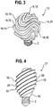
- FIG. 4 shows a further LED lamp 17 with a lamp body 18, which identifies annular structures.
- the annular elevations 19 or depressions 20 are with respect to the longitudinal axis the LED lamp 17 inclined by about 45 °. This has the advantage that the cooling by the convection in horizontal or vertical arrangement of the LED lamp 17 works equally well.
- FIG. 5 shows a further LED lamp 21 with a lamp body 22, in which for a particularly good cooling, the structuring of the surface results in a lamellar structure.
- the slats 23 are arranged parallel to each other.
- FIG. 6 shows the LED lamp 21 off FIG. 5 in supervision.
- the through holes 24 in the lamp body 22 can be seen.
- FIG. 7 and FIG. 8 show a further LED lamp 25 with a lamp body 26, wherein the structuring of the surface also gives a lamellar structure.
- FIG. 8 schematically shows a cross section through the lamp body approximately in the middle height. In this embodiment, however, the slats 27 are arranged in a star shape. How out FIG. 7 to recognize the outline in side view that of a conventional light bulb.
- the coupling of the LED light in the lamp body can be done in various ways. Show this FIG. 9 to FIG. 11 Examples of LED modules that can be used in the above lamp body.
- the LED modules have a carrier equipped with LEDs on.
- a carrier a conventional printed circuit board, a metal core board, or any other suitable pad can be used.
- a metal core board preferably has a structured copper layer on a dielectric, for example made of polyimide or epoxy resin, and a substrate, for example of aluminum, copper or another metal on. The heat generated on the board is emitted very effectively over the cross-sectional area.
- FIG. 9 an LED module 28 with a flat LED carrier 29 extending away from the threaded socket or lamp socket 2. LEDs 30 are mounted on both sides of the carrier 29.
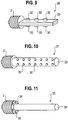
- FIG. 10 shows an LED module 31 with a cylindrical support 32, at the periphery LEDs 30 are mounted regularly.
- FIG. 11 shows an LED module 33 with a flat, round (disk-shaped) support 34, on which LEDs 30 are mounted in a ring, and with a highly thermally conductive, cylindrical core 35.
- the core 35 extends along the longitudinal axis of the LED lamp.
- the core 35 may comprise, for example, carbon, aluminum and / or copper.
- the core 35 is provided with a light-reflecting surface (e.g., film [not numbered]) to improve the luminous efficacy.
- This reflective layer may include barium sulfate, phosphors or other suitable ingredient.
- the core 35 is dimensioned so that it can be inserted into the recess provided in a lamp body.
- LED carriers may have ramifications. This can be advantageous both for the heat distribution and for the distribution of the light emitted by the LEDs within the lamp body.
- FIG. 12 shows a schematic cross section through such an LED lamp 36.
- the carrier is in the form of a frame 37, which has substantially the contours of the LED lamp 36, but strictly complies with the standardized outlines.
- the framework has a vertical section equipped with LEDs 30, from which branchings 38 extend laterally.
- the framework 37 is provided with LEDs 30 and possibly with the necessary driver and control electronics (not shown).
- the framework 37 is embedded in the lamp body 39 of the LED lamp 36.
- the lamp body 39 forms in the region of the ramifications 38 lamellae, which extend in the plane perpendicular to the sheet direction.
- FIG. 13 shows a further embodiment of an LED lamp 40 with a lamp body 41 with a support in the form of a star-shaped framework or with star-shaped outgoing branches 42.
- the lamp body 40 also forms in the region of the branches 42 slats, which are perpendicular to the sheet direction in the plane extend.
- the LED lamps after FIG. 12 and FIG. 13 can be made so that first the carrier is equipped with at least the LEDs, then the carrier is at least partially immersed for a certain time in a bath with the lamp body forming Umhüllmasse and then the Umhüllmasse is cured.
- the lamp base is placed on the loading of the carrier.
- the wrapping compound is made of thermoplastic and / or an epoxy material.
- the cladding diffuses light diffusely by specifically scattering centers are introduced.
- the wrapping compound is also milky white. The curing takes place thermally, chemically and / or with the use of UV light.
- the LED module can be used, for example, precisely fitting in a corresponding recess in the lamp body.
- the LED module may be connected to the lamp body by means of a thread.
- LEDs may be disposed on a flexible support (eg, a so-called flex board).
- the carriers have a good light-reflecting surface.
- the surface of the support may generally include BaS0 4 , phosphors, metallization and much more.
- the LEDs can be arranged flat.
Claims (12)
- Lampe à LED (1 ; 9 ; 13 ; 17 ; 21 ; 25 ; 36 ; 40), comportant- au moins un support (29 ; 32 ; 34) équipé d'au moins une LED (30),- un culot de lampe (2),- au moins un composant de circuit branché entre le culot de lampe (2) et l'au moins une LED (30) et destiné à faire fonctionner l'au moins une LED (30),- un corps de lampe (5 ; 10 ; 14 ; 18 ; 22 ; 26 ; 39 ; 41) en un matériau translucide,- le corps de lampe (5; 10 ; 14 ; 18 ; 22 ; 26 ; 39 ; 41) présentant une structure superficielle (6, 7; 11, 12; 15, 16; 19, 20; 23; 24; 27; 38; 42) en vue du refroidissement par convection thermique et- la structure superficielle comportant plusieurs bosses (6 ; 11 ; 15 ; 19 ; 23 ; 27 ; 38 ; 42),- le corps de lampe (5 ; 10 ; 14 ; 18 ; 22 ; 26 ; 39 ; 41) comportant un évidement afin de loger au moins la partie du support (29 ; 32 ; 34), qui porte l'au moins une LED (30),- les bosses (6 ; 11 ; 15) étant conçues à chaque fois sous la forme d'îles.
- Lampe à LED (1 ; 9) selon la revendication 1, dans laquelle les îles ont à chaque fois une forme de base (6) ronde en vue de dessus ou une forme de base (11) rectangulaire en vue de dessus, la forme de base rectangulaire (11) étant réalisée en particulier avec des angles arrondis.
- Lampe à LED (1 ; 9 ; 13 ; 17 ; 21 ; 25 ; 36 ; 40), comportant- au moins un support (29 ; 32 ; 34) équipé d'au moins une LED (30),- un culot de lampe (2),- au moins un composant de circuit branché entre le culot de lampe (2) et l'au moins une LED (30) et destiné à faire fonctionner l'au moins une LED (30),- un corps de lampe (5 ; 10 ; 14 ; 18 ; 22 ; 26 ; 39 ; 41) en un matériau translucide,- le corps de lampe (5 ; 10 ; 14 ; 18 ; 22 ; 26 ; 39 ; 41) présentant une structure superficielle (6, 7; 11, 12; 15, 16; 19, 20; 23; 24; 27; 38; 42) en vue du refroidissement par convection thermique et- la structure superficielle comportant plusieurs bosses (6 ; 11 ; 15 ; 19 ; 23 ; 27 ; 38 ; 42),- le corps de lampe (5 ; 10 ; 14 ; 18 ; 22 ; 26 ; 39 ; 41) comportant un évidement afin de loger au moins la partie du support (29 ; 32 ; 34) qui porte l'au moins une LED (30),caractérisée en ce que- les bosses (15 ; 19 ; 23 ; 27) présentent à chaque fois une forme de base oblongue et- les bosses (15) s'étendent le long de trajectoires courbes et contiennent en particulier des tronçons en forme de S.
- Lampe à LED (1 ; 9 ; 13 ; 17 ; 21 ; 25 ; 36 ; 40), comportant- au moins un support (29 ; 32 ; 34) équipé d'au moins une LED (30),- un culot de lampe (2),- au moins un composant de circuit branché entre le culot de lampe (2) et l'au moins une LED (30) et destiné à faire fonctionner l'au moins une LED (30),- un corps de lampe (5 ; 10 ; 14 ; 18 ; 22 ; 26 ; 39 ; 41) en un matériau translucide,- le corps de lampe (5 ; 10 ; 14 ; 18 ; 22 ; 26 ; 39 ; 41) présentant une structure superficielle (6, 7; 11, 12; 15, 16; 19, 20; 23; 24; 27; 38; 42) en vue du refroidissement par convection thermique,- le corps de lampe (5 ; 10 ; 14 ; 18 ; 22 ; 26 ; 39 ; 41) comportant un évidement afin de loger au moins la partie du support (29 ; 32 ; 34) qui porte l'au moins une LED (30),caractérisée en ce que- le support (29 ; 32 ; 34) est conçu comme une surface plane et plusieurs LED (30) sont montées dessus de manière répartie,- le support est conçu comme une charpente avec plusieurs ramifications (38 ; 42),- le support (34) a une forme de base plane et ronde à partir de laquelle s'étend un noyau (35) bon conducteur thermique le long de l'axe longitudinal de la lampe à LED et le noyau (35) comportant une surface réfléchissant la lumière,- la surface réfléchissante comporte une substance luminescente et- la lampe à LED comporte en plus un échangeur thermique afin d'échanger de la chaleur entre le support et le corps de lampe.
- Lampe à LED (36) selon la revendication 4, dans laquelle les ramifications (38) sont agencées parallèlement les unes aux autres ou les ramifications (42) sont agencées en forme d'étoile les unes par rapport aux autres en vue de dessus.
- Lampe à LED (1 ; 9 ; 13 ; 17 ; 21 ; 25 ; 36 ; 40), comportant- au moins un support (29 ; 32 ; 34) équipé d'au moins une LED (30),- un culot de lampe (2),- au moins un composant de circuit branché entre le culot de lampe (2) et l'au moins une LED (30) et destiné à faire fonctionner l'au moins une LED (30),- un corps de lampe (5 ; 10 ; 14 ; 18 ; 22 ; 26 ; 39 ; 41) en un matériau translucide,- le corps de lampe (5 ; 10 ; 14 ; 18 ; 22 ; 26 ; 39 ; 41) présentant une structure superficielle (6, 7; 11, 12; 15, 16; 19, 20; 23; 24; 27; 38; 42) en vue du refroidissement par convection thermique,- le corps de lampe (5 ; 10 ; 14 ; 18 ; 22 ; 26 ; 39 ; 41) comportant un évidement afin de loger au moins la partie du support (29 ; 32 ; 34) qui porte l'au moins une LED (30),caractérisée en ce que- un fluide de refroidissement se trouve entre le corps de lampe et le support,- le support étant réalisé flexible de telle sorte que, lors d'une modification de l'orientation de la lampe à LED, il fléchit sous l'action de la force de gravité et les LED sont ainsi déplacées vers le bas.
- Lampe à LED (1 ; 9 ; 13 ; 17 ; 21 ; 25 ; 36 ; 40), comportant- au moins un support (29 ; 32 ; 34) équipé d'au moins une LED (30),- un culot de lampe (2),- au moins un composant de circuit branché entre le culot de lampe (2) et l'au moins une LED (30) et destiné à faire fonctionner l'au moins une LED (30),- un corps de lampe (5 ; 10 ; 14 ; 18 ; 22 ; 26 ; 39 ; 41) en un matériau translucide,- le corps de lampe (5 ; 10 ; 14 ; 18 ; 22 ; 26 ; 39 ; 41) présentant une structure superficielle (6, 7; 11, 12; 15, 16; 19, 20; 23; 24; 27; 38; 42) en vue du refroidissement par convection thermique,- le corps de lampe (5 ; 10 ; 14 ; 18 ; 22 ; 26 ; 39 ; 41) comportant un évidement afin de loger au moins la partie du support (29 ; 32 ; 34) qui porte l'au moins une LED (30),caractérisée en ce que- le corps de lampe (5 ; 10 ; 14 ; 18 ; 22 ; 26 ; 39 ; 41) est formé par un réseau de fils.
- Lampe à LED (1; 9; 13; 17; 21; 25; 36; 40) selon l'une des revendications précédentes, caractérisée en ce que- le corps de lampe (5 ; 10 ; 14 ; 18 ; 22 ; 26 ; 39 ; 41) comporte un évidement afin de loger au moins la partie du support (29 ; 32 ; 34) qui porte l'au moins une LED (30),- les bosses (15 ; 19 ; 23 ; 27) présentent à chaque fois une forme de base oblongue et- les bosses (19) présentent à chaque fois une forme de base annulaire.
- Lampe à LED (17) selon la revendication 8, dans laquelle les bosses (19) sont à chaque fois inclinées par rapport à un axe de symétrie, en particulier l'axe longitudinal, de la lampe à LED, en particulier avec une inclinaison dans une plage allant jusqu'à 45°, spécialement avec une inclinaison de 45°.
- Lampe à LED (1; 9; 13; 17; 21; 25; 36; 40) selon l'une des revendications précédentes, caractérisée en ce que- le corps de lampe (5 ; 10 ; 14 ; 18 ; 22 ; 26 ; 39 ; 41) comporte un évidement afin de loger au moins la partie du support (29 ; 32 ; 34) qui porte l'au moins une LED (30) et- un fluide de refroidissement qui contient une substance luminescente se trouve entre le corps de lampe et le support.
- Lampe à LED (1; 9; 13; 17; 21; 25; 36; 40) selon l'une des revendications précédentes, caractérisée en ce que- le corps de lampe (5 ; 10 ; 14 ; 18 ; 22 ; 26 ; 39 ; 41) comporte un évidement afin de loger au moins la partie du support (29 ; 32 ; 34) qui porte l'au moins une LED (30) et- un fluide de refroidissement se trouve entre le corps de lampe et le support,- le fluide de refroidissement étant peu visqueux et/ou ayant une capacité thermique élevée et/ou une chaleur latente de transformation élevée lors d'une transition d'une phase à une autre phase.
- Lampe à LED selon l'une des revendications 10 à 11, dans laquelle le fluide de refroidissement disperse la lumière de manière diffuse.
Applications Claiming Priority (2)
| Application Number | Priority Date | Filing Date | Title |
|---|---|---|---|
| DE102007037820A DE102007037820A1 (de) | 2007-08-10 | 2007-08-10 | LED-Lampe |
| PCT/EP2008/006571 WO2009021695A1 (fr) | 2007-08-10 | 2008-08-08 | Lampe à del |
Publications (2)
| Publication Number | Publication Date |
|---|---|
| EP2188566A1 EP2188566A1 (fr) | 2010-05-26 |
| EP2188566B1 true EP2188566B1 (fr) | 2017-07-12 |
Family
ID=39765022
Family Applications (1)
| Application Number | Title | Priority Date | Filing Date |
|---|---|---|---|
| EP08785464.2A Not-in-force EP2188566B1 (fr) | 2007-08-10 | 2008-08-08 | Lampe à del |
Country Status (5)
| Country | Link |
|---|---|
| US (1) | US8662712B2 (fr) |
| EP (1) | EP2188566B1 (fr) |
| CN (2) | CN102620154B (fr) |
| DE (1) | DE102007037820A1 (fr) |
| WO (1) | WO2009021695A1 (fr) |
Families Citing this family (50)
| Publication number | Priority date | Publication date | Assignee | Title |
|---|---|---|---|---|
| US10340424B2 (en) | 2002-08-30 | 2019-07-02 | GE Lighting Solutions, LLC | Light emitting diode component |
| US8007286B1 (en) | 2008-03-18 | 2011-08-30 | Metrospec Technology, Llc | Circuit boards interconnected by overlapping plated through holes portions |
| US11266014B2 (en) | 2008-02-14 | 2022-03-01 | Metrospec Technology, L.L.C. | LED lighting systems and method |
| US10334735B2 (en) | 2008-02-14 | 2019-06-25 | Metrospec Technology, L.L.C. | LED lighting systems and methods |
| US8851356B1 (en) | 2008-02-14 | 2014-10-07 | Metrospec Technology, L.L.C. | Flexible circuit board interconnection and methods |
| US8143631B2 (en) | 2008-03-06 | 2012-03-27 | Metrospec Technology Llc | Layered structure for use with high power light emitting diode systems |
| US8410720B2 (en) | 2008-04-07 | 2013-04-02 | Metrospec Technology, LLC. | Solid state lighting circuit and controls |
| DE102008047933A1 (de) * | 2008-09-19 | 2010-04-15 | Osram Gesellschaft mit beschränkter Haftung | Beleuchtungsvorrichtung mit einer Leuchtdiode |
| DE102009008096B4 (de) * | 2009-02-09 | 2016-10-27 | Osram Gmbh | Kühlkörper für eine Leuchtvorrichtung |
| DE102009009520A1 (de) * | 2009-02-18 | 2010-08-19 | Osram Opto Semiconductors Gmbh | Steckmodul für ein modular aufgebautes Leuchtmittel, Leuchtmodul für das Leuchtmittel sowie modular aufgebautes Leuchtmittel |
| DE102009019227A1 (de) * | 2009-04-28 | 2011-01-13 | Ledon Lighting Jennersdorf Gmbh | LED lamp |
| RU2538100C2 (ru) * | 2009-05-28 | 2015-01-10 | Конинклейке Филипс Электроникс Н.В. | Осветительное устройство с корпусом, заключающим в себе источник света |
| EP2623847A1 (fr) * | 2009-05-28 | 2013-08-07 | Koninklijke Philips Electronics N.V. | Appareil d'éclairage et méthode d'assemblage |
| TW201109579A (en) * | 2009-09-15 | 2011-03-16 | Advanced Connectek Inc | Structure of LED lamp |
| US8593040B2 (en) * | 2009-10-02 | 2013-11-26 | Ge Lighting Solutions Llc | LED lamp with surface area enhancing fins |
| US8414151B2 (en) | 2009-10-02 | 2013-04-09 | GE Lighting Solutions, LLC | Light emitting diode (LED) based lamp |
| US9103507B2 (en) | 2009-10-02 | 2015-08-11 | GE Lighting Solutions, LLC | LED lamp with uniform omnidirectional light intensity output |
| DE102009051763A1 (de) * | 2009-11-03 | 2011-05-05 | Osram Gesellschaft mit beschränkter Haftung | Beleuchtungsvorrichtung mit einem Kolben |
| CA2789267A1 (fr) * | 2010-02-08 | 2011-08-11 | Ole K. Nilssen | Lampe refroidie par evaporation |
| GB2477994A (en) * | 2010-02-23 | 2011-08-24 | Ecolumens Ltd | Liquid cooled semiconductor light |
| PL2542826T3 (pl) * | 2010-03-03 | 2020-03-31 | Philips Lighting Holding B.V. | Lampa elektryczna zawierająca odbłyśnik do przekazywania ciepła ze źródła światła |
| DE102010013538A1 (de) | 2010-03-31 | 2011-10-06 | Ledo Led Technologie Gmbh | LED-Leuchte als Glühbirnensubstitut |
| WO2011146677A2 (fr) * | 2010-05-20 | 2011-11-24 | Light Prescriptions Innovators, Llc | Ampoule à del ayant un diffuseur sphérique translucide et luminophore distant sur celle-ci |
| US10400959B2 (en) * | 2010-11-09 | 2019-09-03 | Lumination Llc | LED lamp |
| RU2447543C1 (ru) * | 2011-01-11 | 2012-04-10 | Юлия Алексеевна Щепочкина | Лампа светодиодная |
| RU2447542C1 (ru) * | 2011-01-11 | 2012-04-10 | Юлия Алексеевна Щепочкина | Лампа светодиодная |
| US9127816B2 (en) | 2011-01-19 | 2015-09-08 | GE Lighting Solutions, LLC | LED light engine/heat sink assembly |
| US20130154481A1 (en) * | 2011-10-31 | 2013-06-20 | Densen Cao | Led light source |
| DE102011085646A1 (de) * | 2011-11-03 | 2013-05-08 | Osram Gmbh | Halbleiterlampe mit Kolben |
| US8668366B2 (en) | 2011-12-07 | 2014-03-11 | Tsmc Solid State Lighting Ltd. | Energy star compliant LED lamp |
| RU2504714C2 (ru) * | 2012-02-15 | 2014-01-20 | Общество с ограниченной ответственностью "Тегас Электрик" | Способ сборки светодиодной лампы и лампа светодиодная |
| US9500355B2 (en) | 2012-05-04 | 2016-11-22 | GE Lighting Solutions, LLC | Lamp with light emitting elements surrounding active cooling device |
| CN102777791B (zh) * | 2012-07-12 | 2015-09-09 | 深圳和而泰照明科技有限公司 | 灯具及其全光角led灯泡 |
| DE202012009071U1 (de) | 2012-09-21 | 2012-11-08 | Carsten Schmidt | LED-Leuchte mit verbessertem Rückstrahlverhalten |
| DE102012217292A1 (de) * | 2012-09-25 | 2014-03-27 | Zumtobel Lighting Gmbh | LED-Leuchte |
| US20150354804A1 (en) * | 2013-01-10 | 2015-12-10 | Franco MIRABELLI | Outdoor public lighting lamp having light-emitting diodes and street lamp or lamp-post provided with such a lamp |
| US10565835B2 (en) | 2013-01-21 | 2020-02-18 | Rtc Inc. | Control and monitoring of light-emitting-diode (LED) bulbs |
| US20140203939A1 (en) * | 2013-01-21 | 2014-07-24 | Rtc Inc. | Control and monitoring of light-emitting-diode (led) bulbs |
| US10634310B2 (en) | 2013-11-25 | 2020-04-28 | Signify Holding B.V. | Method for manufacturing a lighting device |
| EP3276257A1 (fr) | 2013-12-17 | 2018-01-31 | Koninklijke Philips N.V. | Lampe à del avec faisceau faible et élevé |
| USD748840S1 (en) * | 2014-05-27 | 2016-02-02 | Lumens Co., Ltd | Ceiling light fixture |
| TW201600790A (zh) * | 2014-06-27 | 2016-01-01 | Formosa Optronics Co Ltd | 全周光球泡型燈具 |
| EP3195711A4 (fr) * | 2014-09-15 | 2018-08-29 | D'Onofrio, Nicholas, Michael | Carte de circuit imprimé à noyau métallique refroidi par liquide |
| US9401468B2 (en) * | 2014-12-24 | 2016-07-26 | GE Lighting Solutions, LLC | Lamp with LED chips cooled by a phase transformation loop |
| USD774474S1 (en) * | 2015-02-04 | 2016-12-20 | Xiaofeng Li | Light emitting diodes on a printed circuit board |
| CN205079067U (zh) * | 2015-07-21 | 2016-03-09 | 上海本星电子科技有限公司 | 遥控灯泡及其光束遥控器 |
| CN106468408A (zh) * | 2015-08-17 | 2017-03-01 | 上海本星电子科技有限公司 | 设有遮光部件的遥控灯及其锥形光束遥控器 |
| EP3179153A1 (fr) * | 2015-12-11 | 2017-06-14 | Epistar Corporation | Appareil d'éclairage |
| US10578510B2 (en) * | 2016-11-28 | 2020-03-03 | Applied Materials, Inc. | Device for desorbing molecules from chamber walls |
| US10849200B2 (en) | 2018-09-28 | 2020-11-24 | Metrospec Technology, L.L.C. | Solid state lighting circuit with current bias and method of controlling thereof |
Citations (1)
| Publication number | Priority date | Publication date | Assignee | Title |
|---|---|---|---|---|
| DE102007017900A1 (de) * | 2007-04-13 | 2008-10-16 | Noctron Holding S.A. | Leuchtmittel |
Family Cites Families (18)
| Publication number | Priority date | Publication date | Assignee | Title |
|---|---|---|---|---|
| US5890794A (en) * | 1996-04-03 | 1999-04-06 | Abtahi; Homayoon | Lighting units |
| DE69936375T2 (de) * | 1998-09-17 | 2008-02-28 | Koninklijke Philips Electronics N.V. | Led-leuchte |
| US6793374B2 (en) * | 1998-09-17 | 2004-09-21 | Simon H. A. Begemann | LED lamp |
| DE20018435U1 (de) | 2000-10-27 | 2001-02-22 | Shining Blick Entpr Co | Glühbirne mit darin enthaltenen biegbaren Lampenbirnchen |
| GB2379790A (en) * | 2001-08-21 | 2003-03-19 | Green Logic Associates Ltd | An illuminated light globe containing two immiscible liquids |
| WO2003059013A1 (fr) * | 2002-01-10 | 2003-07-17 | Patent - Treuhand - Gesellschaft für Elektrische Glühlampen mbH | Lampe |
| JP2004296245A (ja) * | 2003-03-26 | 2004-10-21 | Matsushita Electric Works Ltd | Ledランプ |
| US6880956B2 (en) * | 2003-07-31 | 2005-04-19 | A L Lightech, Inc. | Light source with heat transfer arrangement |
| MXPA06009907A (es) * | 2004-03-03 | 2006-12-14 | Johnson & Son Inc S C | Foco de luz de led con emision de ingrediente activo. |
| DE102005013208A1 (de) * | 2004-03-21 | 2005-10-27 | Späth, Christian, Dipl.-Designer | LED-Leuchtdioden Leuchte |
| WO2006020535A2 (fr) * | 2004-08-09 | 2006-02-23 | Valeo Sylvania Llc | Reflecteur de refraction a ampoule del |
| US20060034077A1 (en) * | 2004-08-10 | 2006-02-16 | Tsu-Kang Chang | White light bulb assembly using LED as a light source |
| CA2478001A1 (fr) * | 2004-08-18 | 2006-02-18 | Remco | Ampoule electrique a del |
| DE202005008411U1 (de) * | 2005-05-30 | 2005-07-28 | Huang, Hsien-Jung, Yung-Ho | Kühlkörper für ein LED-Leuchtelement |
| JP4410721B2 (ja) * | 2005-05-02 | 2010-02-03 | シチズン電子株式会社 | バルブ型led光源 |
| CN2864338Y (zh) * | 2006-01-10 | 2007-01-31 | 孙文明 | Led棒状节能灯泡 |
| WO2007089581A2 (fr) | 2006-01-26 | 2007-08-09 | Great American Technologies, Inc. | Ampoule électrique télécommandée par diode électroluminescente |
| DE202007003679U1 (de) * | 2007-03-09 | 2007-05-16 | Hong Kuan Technology Co., Ltd., Sinjhuang City | Leuchtdiodenlampe |
-
2007
- 2007-08-10 DE DE102007037820A patent/DE102007037820A1/de not_active Withdrawn
-
2008
- 2008-08-08 US US12/672,713 patent/US8662712B2/en not_active Expired - Fee Related
- 2008-08-08 EP EP08785464.2A patent/EP2188566B1/fr not_active Not-in-force
- 2008-08-08 CN CN201210012199.0A patent/CN102620154B/zh not_active Expired - Fee Related
- 2008-08-08 CN CN2008801028755A patent/CN101815894B/zh not_active Expired - Fee Related
- 2008-08-08 WO PCT/EP2008/006571 patent/WO2009021695A1/fr active Application Filing
Patent Citations (1)
| Publication number | Priority date | Publication date | Assignee | Title |
|---|---|---|---|---|
| DE102007017900A1 (de) * | 2007-04-13 | 2008-10-16 | Noctron Holding S.A. | Leuchtmittel |
Also Published As
| Publication number | Publication date |
|---|---|
| WO2009021695A1 (fr) | 2009-02-19 |
| CN102620154B (zh) | 2015-04-01 |
| DE102007037820A1 (de) | 2009-02-12 |
| US20120188771A1 (en) | 2012-07-26 |
| CN102620154A (zh) | 2012-08-01 |
| US8662712B2 (en) | 2014-03-04 |
| CN101815894A (zh) | 2010-08-25 |
| CN101815894B (zh) | 2012-03-21 |
| EP2188566A1 (fr) | 2010-05-26 |
Similar Documents
| Publication | Publication Date | Title |
|---|---|---|
| EP2188566B1 (fr) | Lampe à del | |
| DE102009023052B4 (de) | Leuchtmodul und Leuchtvorrichtung | |
| EP2198196B1 (fr) | Lampe | |
| EP3132180B1 (fr) | Module à del servant à émettre une lumière blanche | |
| DE102008016458A1 (de) | Leiterplatte | |
| DE102012207608A1 (de) | Halbleiter-retrofitlampe mit zweiseitig angeordneten anschlusselementen | |
| DE202007008258U1 (de) | LED-Leuchtmittel | |
| DE102017104827A1 (de) | Lichtemittierendes modul und beleuchtungsapparat | |
| EP2270387B1 (fr) | Lampe plate à DEL | |
| DE102007043904A1 (de) | Leucht-Vorrichtung | |
| DE102014109717A1 (de) | Substrat, Licht emittierende Vorrichtung, Beleuchtungslichtquelle und Leuchteinrichtung | |
| DE112011106000T5 (de) | Thermomanagement für Leuchtdioden | |
| WO2011012444A1 (fr) | Dispositif d'éclairage et procédé pour monter un dispositif d'éclairage | |
| DE102014110087A1 (de) | Licht emittierendes Modul, Beleuchtungsvorrichtung und Beleuchtungsausstattung | |
| EP2443390B1 (fr) | Radiateur pour del | |
| EP2697557B1 (fr) | Dispositif d'éclairage | |
| WO2010133631A1 (fr) | Dissipateur thermique pour dispositif d'éclairage | |
| DE102013201952A1 (de) | Halbleiter-Leuchtmodul mit lichtdurchlässiger Vergussmasse | |
| WO2013149890A1 (fr) | Dispositif d'éclairage à del comprenant des diodes électroluminescentes de couleur menthe et de couleur ambre | |
| DE102018101050A1 (de) | Lichtemittierende Vorrichtung und Beleuchtungsvorrichtung | |
| EP2443389A1 (fr) | Corps de refroidissement pour éléments luminescents à semi-conducteur | |
| DE102008016097A1 (de) | Beleuchtungseinrichtung und Abdeckungselement | |
| DE102012205472A1 (de) | Halbleiterlampe mit kolben | |
| DE202011000301U1 (de) | Ein Kühlkörper und eine Lampe mit lichtemittierender Diode | |
| WO2012041734A2 (fr) | Module destiné à un dispositif d'éclairage et dispositif d'éclairage |
Legal Events
| Date | Code | Title | Description |
|---|---|---|---|
| PUAI | Public reference made under article 153(3) epc to a published international application that has entered the european phase |
Free format text: ORIGINAL CODE: 0009012 |
|
| 17P | Request for examination filed |
Effective date: 20100310 |
|
| AK | Designated contracting states |
Kind code of ref document: A1 Designated state(s): AT BE BG CH CY CZ DE DK EE ES FI FR GB GR HR HU IE IS IT LI LT LU LV MC MT NL NO PL PT RO SE SI SK TR |
|
| AX | Request for extension of the european patent |
Extension state: AL BA MK RS |
|
| RIC1 | Information provided on ipc code assigned before grant |
Ipc: F21V 29/00 20060101ALI20100426BHEP Ipc: F21K 99/00 20100101AFI20100426BHEP |
|
| DAX | Request for extension of the european patent (deleted) | ||
| RAP1 | Party data changed (applicant data changed or rights of an application transferred) |
Owner name: OSRAM AG |
|
| RAP1 | Party data changed (applicant data changed or rights of an application transferred) |
Owner name: OSRAM GMBH |
|
| RAP1 | Party data changed (applicant data changed or rights of an application transferred) |
Owner name: OSRAM GMBH |
|
| 17Q | First examination report despatched |
Effective date: 20140905 |
|
| GRAP | Despatch of communication of intention to grant a patent |
Free format text: ORIGINAL CODE: EPIDOSNIGR1 |
|
| INTG | Intention to grant announced |
Effective date: 20170216 |
|
| GRAS | Grant fee paid |
Free format text: ORIGINAL CODE: EPIDOSNIGR3 |
|
| GRAA | (expected) grant |
Free format text: ORIGINAL CODE: 0009210 |
|
| RAP1 | Party data changed (applicant data changed or rights of an application transferred) |
Owner name: LEDVANCE GMBH |
|
| AK | Designated contracting states |
Kind code of ref document: B1 Designated state(s): AT BE BG CH CY CZ DE DK EE ES FI FR GB GR HR HU IE IS IT LI LT LU LV MC MT NL NO PL PT RO SE SI SK TR |
|
| REG | Reference to a national code |
Ref country code: GB Ref legal event code: FG4D Free format text: NOT ENGLISH |
|
| REG | Reference to a national code |
Ref country code: CH Ref legal event code: EP |
|
| REG | Reference to a national code |
Ref country code: AT Ref legal event code: REF Ref document number: 908683 Country of ref document: AT Kind code of ref document: T Effective date: 20170715 |
|
| REG | Reference to a national code |
Ref country code: IE Ref legal event code: FG4D Free format text: LANGUAGE OF EP DOCUMENT: GERMAN |
|
| REG | Reference to a national code |
Ref country code: DE Ref legal event code: R096 Ref document number: 502008015450 Country of ref document: DE |
|
| REG | Reference to a national code |
Ref country code: NL Ref legal event code: MP Effective date: 20170712 |
|
| REG | Reference to a national code |
Ref country code: LT Ref legal event code: MG4D |
|
| PG25 | Lapsed in a contracting state [announced via postgrant information from national office to epo] |
Ref country code: SE Free format text: LAPSE BECAUSE OF FAILURE TO SUBMIT A TRANSLATION OF THE DESCRIPTION OR TO PAY THE FEE WITHIN THE PRESCRIBED TIME-LIMIT Effective date: 20170712 Ref country code: HR Free format text: LAPSE BECAUSE OF FAILURE TO SUBMIT A TRANSLATION OF THE DESCRIPTION OR TO PAY THE FEE WITHIN THE PRESCRIBED TIME-LIMIT Effective date: 20170712 Ref country code: NO Free format text: LAPSE BECAUSE OF FAILURE TO SUBMIT A TRANSLATION OF THE DESCRIPTION OR TO PAY THE FEE WITHIN THE PRESCRIBED TIME-LIMIT Effective date: 20171012 Ref country code: NL Free format text: LAPSE BECAUSE OF FAILURE TO SUBMIT A TRANSLATION OF THE DESCRIPTION OR TO PAY THE FEE WITHIN THE PRESCRIBED TIME-LIMIT Effective date: 20170712 Ref country code: LT Free format text: LAPSE BECAUSE OF FAILURE TO SUBMIT A TRANSLATION OF THE DESCRIPTION OR TO PAY THE FEE WITHIN THE PRESCRIBED TIME-LIMIT Effective date: 20170712 Ref country code: FI Free format text: LAPSE BECAUSE OF FAILURE TO SUBMIT A TRANSLATION OF THE DESCRIPTION OR TO PAY THE FEE WITHIN THE PRESCRIBED TIME-LIMIT Effective date: 20170712 |
|
| PG25 | Lapsed in a contracting state [announced via postgrant information from national office to epo] |
Ref country code: ES Free format text: LAPSE BECAUSE OF FAILURE TO SUBMIT A TRANSLATION OF THE DESCRIPTION OR TO PAY THE FEE WITHIN THE PRESCRIBED TIME-LIMIT Effective date: 20170712 Ref country code: PL Free format text: LAPSE BECAUSE OF FAILURE TO SUBMIT A TRANSLATION OF THE DESCRIPTION OR TO PAY THE FEE WITHIN THE PRESCRIBED TIME-LIMIT Effective date: 20170712 Ref country code: GR Free format text: LAPSE BECAUSE OF FAILURE TO SUBMIT A TRANSLATION OF THE DESCRIPTION OR TO PAY THE FEE WITHIN THE PRESCRIBED TIME-LIMIT Effective date: 20171013 Ref country code: IS Free format text: LAPSE BECAUSE OF FAILURE TO SUBMIT A TRANSLATION OF THE DESCRIPTION OR TO PAY THE FEE WITHIN THE PRESCRIBED TIME-LIMIT Effective date: 20171112 Ref country code: BG Free format text: LAPSE BECAUSE OF FAILURE TO SUBMIT A TRANSLATION OF THE DESCRIPTION OR TO PAY THE FEE WITHIN THE PRESCRIBED TIME-LIMIT Effective date: 20171012 Ref country code: LV Free format text: LAPSE BECAUSE OF FAILURE TO SUBMIT A TRANSLATION OF THE DESCRIPTION OR TO PAY THE FEE WITHIN THE PRESCRIBED TIME-LIMIT Effective date: 20170712 |
|
| REG | Reference to a national code |
Ref country code: CH Ref legal event code: PL |
|
| REG | Reference to a national code |
Ref country code: DE Ref legal event code: R097 Ref document number: 502008015450 Country of ref document: DE |
|
| PG25 | Lapsed in a contracting state [announced via postgrant information from national office to epo] |
Ref country code: RO Free format text: LAPSE BECAUSE OF FAILURE TO SUBMIT A TRANSLATION OF THE DESCRIPTION OR TO PAY THE FEE WITHIN THE PRESCRIBED TIME-LIMIT Effective date: 20170712 Ref country code: MC Free format text: LAPSE BECAUSE OF FAILURE TO SUBMIT A TRANSLATION OF THE DESCRIPTION OR TO PAY THE FEE WITHIN THE PRESCRIBED TIME-LIMIT Effective date: 20170712 Ref country code: CH Free format text: LAPSE BECAUSE OF NON-PAYMENT OF DUE FEES Effective date: 20170831 Ref country code: DK Free format text: LAPSE BECAUSE OF FAILURE TO SUBMIT A TRANSLATION OF THE DESCRIPTION OR TO PAY THE FEE WITHIN THE PRESCRIBED TIME-LIMIT Effective date: 20170712 Ref country code: CZ Free format text: LAPSE BECAUSE OF FAILURE TO SUBMIT A TRANSLATION OF THE DESCRIPTION OR TO PAY THE FEE WITHIN THE PRESCRIBED TIME-LIMIT Effective date: 20170712 Ref country code: LI Free format text: LAPSE BECAUSE OF NON-PAYMENT OF DUE FEES Effective date: 20170831 |
|
| PLBE | No opposition filed within time limit |
Free format text: ORIGINAL CODE: 0009261 |
|
| STAA | Information on the status of an ep patent application or granted ep patent |
Free format text: STATUS: NO OPPOSITION FILED WITHIN TIME LIMIT |
|
| REG | Reference to a national code |
Ref country code: FR Ref legal event code: ST Effective date: 20180430 |
|
| REG | Reference to a national code |
Ref country code: IE Ref legal event code: MM4A |
|
| PG25 | Lapsed in a contracting state [announced via postgrant information from national office to epo] |
Ref country code: IT Free format text: LAPSE BECAUSE OF FAILURE TO SUBMIT A TRANSLATION OF THE DESCRIPTION OR TO PAY THE FEE WITHIN THE PRESCRIBED TIME-LIMIT Effective date: 20170712 Ref country code: EE Free format text: LAPSE BECAUSE OF FAILURE TO SUBMIT A TRANSLATION OF THE DESCRIPTION OR TO PAY THE FEE WITHIN THE PRESCRIBED TIME-LIMIT Effective date: 20170712 Ref country code: SK Free format text: LAPSE BECAUSE OF FAILURE TO SUBMIT A TRANSLATION OF THE DESCRIPTION OR TO PAY THE FEE WITHIN THE PRESCRIBED TIME-LIMIT Effective date: 20170712 |
|
| REG | Reference to a national code |
Ref country code: BE Ref legal event code: MM Effective date: 20170831 |
|
| 26N | No opposition filed |
Effective date: 20180413 |
|
| GBPC | Gb: european patent ceased through non-payment of renewal fee |
Effective date: 20171012 |
|
| PG25 | Lapsed in a contracting state [announced via postgrant information from national office to epo] |
Ref country code: LU Free format text: LAPSE BECAUSE OF NON-PAYMENT OF DUE FEES Effective date: 20170808 |
|
| PG25 | Lapsed in a contracting state [announced via postgrant information from national office to epo] |
Ref country code: GB Free format text: LAPSE BECAUSE OF NON-PAYMENT OF DUE FEES Effective date: 20171012 Ref country code: IE Free format text: LAPSE BECAUSE OF NON-PAYMENT OF DUE FEES Effective date: 20170808 |
|
| PG25 | Lapsed in a contracting state [announced via postgrant information from national office to epo] |
Ref country code: BE Free format text: LAPSE BECAUSE OF NON-PAYMENT OF DUE FEES Effective date: 20170831 Ref country code: FR Free format text: LAPSE BECAUSE OF NON-PAYMENT OF DUE FEES Effective date: 20170912 Ref country code: SI Free format text: LAPSE BECAUSE OF FAILURE TO SUBMIT A TRANSLATION OF THE DESCRIPTION OR TO PAY THE FEE WITHIN THE PRESCRIBED TIME-LIMIT Effective date: 20170712 |
|
| PG25 | Lapsed in a contracting state [announced via postgrant information from national office to epo] |
Ref country code: MT Free format text: LAPSE BECAUSE OF FAILURE TO SUBMIT A TRANSLATION OF THE DESCRIPTION OR TO PAY THE FEE WITHIN THE PRESCRIBED TIME-LIMIT Effective date: 20170712 |
|
| REG | Reference to a national code |
Ref country code: AT Ref legal event code: MM01 Ref document number: 908683 Country of ref document: AT Kind code of ref document: T Effective date: 20170808 |
|
| PG25 | Lapsed in a contracting state [announced via postgrant information from national office to epo] |
Ref country code: AT Free format text: LAPSE BECAUSE OF NON-PAYMENT OF DUE FEES Effective date: 20170808 |
|
| PG25 | Lapsed in a contracting state [announced via postgrant information from national office to epo] |
Ref country code: HU Free format text: LAPSE BECAUSE OF FAILURE TO SUBMIT A TRANSLATION OF THE DESCRIPTION OR TO PAY THE FEE WITHIN THE PRESCRIBED TIME-LIMIT; INVALID AB INITIO Effective date: 20080808 |
|
| PG25 | Lapsed in a contracting state [announced via postgrant information from national office to epo] |
Ref country code: CY Free format text: LAPSE BECAUSE OF NON-PAYMENT OF DUE FEES Effective date: 20170712 |
|
| PGFP | Annual fee paid to national office [announced via postgrant information from national office to epo] |
Ref country code: DE Payment date: 20191031 Year of fee payment: 12 |
|
| PG25 | Lapsed in a contracting state [announced via postgrant information from national office to epo] |
Ref country code: TR Free format text: LAPSE BECAUSE OF FAILURE TO SUBMIT A TRANSLATION OF THE DESCRIPTION OR TO PAY THE FEE WITHIN THE PRESCRIBED TIME-LIMIT Effective date: 20170712 |
|
| PG25 | Lapsed in a contracting state [announced via postgrant information from national office to epo] |
Ref country code: PT Free format text: LAPSE BECAUSE OF FAILURE TO SUBMIT A TRANSLATION OF THE DESCRIPTION OR TO PAY THE FEE WITHIN THE PRESCRIBED TIME-LIMIT Effective date: 20170712 |
|
| REG | Reference to a national code |
Ref country code: DE Ref legal event code: R119 Ref document number: 502008015450 Country of ref document: DE |
|
| PG25 | Lapsed in a contracting state [announced via postgrant information from national office to epo] |
Ref country code: DE Free format text: LAPSE BECAUSE OF NON-PAYMENT OF DUE FEES Effective date: 20210302 |