EP2187478A1 - Anschlussstück, Drahtverbindungsstruktur und Verbindungsverfahren - Google Patents
Anschlussstück, Drahtverbindungsstruktur und Verbindungsverfahren Download PDFInfo
- Publication number
- EP2187478A1 EP2187478A1 EP09011557A EP09011557A EP2187478A1 EP 2187478 A1 EP2187478 A1 EP 2187478A1 EP 09011557 A EP09011557 A EP 09011557A EP 09011557 A EP09011557 A EP 09011557A EP 2187478 A1 EP2187478 A1 EP 2187478A1
- Authority
- EP
- European Patent Office
- Prior art keywords
- conductor
- crimping pieces
- portions
- base wall
- connection structure
- Prior art date
- Legal status (The legal status is an assumption and is not a legal conclusion. Google has not performed a legal analysis and makes no representation as to the accuracy of the status listed.)
- Withdrawn
Links
Images


Classifications
-
- H—ELECTRICITY
- H01—ELECTRIC ELEMENTS
- H01R—ELECTRICALLY-CONDUCTIVE CONNECTIONS; STRUCTURAL ASSOCIATIONS OF A PLURALITY OF MUTUALLY-INSULATED ELECTRICAL CONNECTING ELEMENTS; COUPLING DEVICES; CURRENT COLLECTORS
- H01R4/00—Electrically-conductive connections between two or more conductive members in direct contact, i.e. touching one another; Means for effecting or maintaining such contact; Electrically-conductive connections having two or more spaced connecting locations for conductors and using contact members penetrating insulation
- H01R4/10—Electrically-conductive connections between two or more conductive members in direct contact, i.e. touching one another; Means for effecting or maintaining such contact; Electrically-conductive connections having two or more spaced connecting locations for conductors and using contact members penetrating insulation effected solely by twisting, wrapping, bending, crimping, or other permanent deformation
- H01R4/18—Electrically-conductive connections between two or more conductive members in direct contact, i.e. touching one another; Means for effecting or maintaining such contact; Electrically-conductive connections having two or more spaced connecting locations for conductors and using contact members penetrating insulation effected solely by twisting, wrapping, bending, crimping, or other permanent deformation by crimping
- H01R4/183—Electrically-conductive connections between two or more conductive members in direct contact, i.e. touching one another; Means for effecting or maintaining such contact; Electrically-conductive connections having two or more spaced connecting locations for conductors and using contact members penetrating insulation effected solely by twisting, wrapping, bending, crimping, or other permanent deformation by crimping for cylindrical elongated bodies, e.g. cables having circular cross-section
- H01R4/184—Electrically-conductive connections between two or more conductive members in direct contact, i.e. touching one another; Means for effecting or maintaining such contact; Electrically-conductive connections having two or more spaced connecting locations for conductors and using contact members penetrating insulation effected solely by twisting, wrapping, bending, crimping, or other permanent deformation by crimping for cylindrical elongated bodies, e.g. cables having circular cross-section comprising a U-shaped wire-receiving portion
Definitions
- the present invention relates to a terminal fitting, a wire connection structure and to a connecting method therefor.
- Japanese Unexamined Patent Publication No. 2005-222815 discloses a structure for connecting a terminal fitting including a wire barrel portion in the form of an open barrel, in which a pair of crimping pieces stand up from the opposite left and right edges of a bottom wall, and a front end portion of a wire including a conductor formed by twisting a plurality of metal thin wires.
- the crimping pieces compress the conductor while surrounding it, whereby the wire is electrically connected.
- a front end portion of the conductor projects forward from the front end of the wire barrel portion.
- the wire barrel portion needs to be more strongly fastened to remove an oxide film. If the crimping force is strengthened, the metal thin wires constituting the conductor are loosened before the wire barrel portion and front end portions of the loosened thin metal wires are deformed to spread out. Some of the spread metal thin wires are bent up toward a side opposite to the bottom wall. These bent-up metal thin wires may interfere with other members.
- the present invention was developed in view of the above situation and an object thereof is to suppress or reduce a formation of a bent-up front end portion of a conductor projecting from a wire barrel portion.
- connection structure for a terminal fitting including a wire barrel portion in the form of at least one open barrel, in which one or more, preferably a pair of crimping pieces project from a base wall, wherein:
- the conductor Since the conductor is to be displaced toward the base wall by the one or more pressing portions at or near the front end portions of the ceiling walls of the one or more crimping pieces, the height of the front end portion of the conductor projecting from the front end of the wire barrel portion from the base wall is reduced or suppressed low. Thus, even if the conductor is bent up toward the side opposite to the base wall, the height of the bent-up part is reduced or suppressed to be low.
- connection structure for a terminal fitting including a wire barrel portion in the form of an open barrel, in which a pair of crimping pieces stand up from the opposite left and right edges of a bottom wall, and a front end portion of a wire including a conductor formed by twisting a plurality of metal thin wires, wherein:
- the conductor Since the conductor is displaced toward the bottom wall by the pressing portions at the front end portions of the upper walls of the crimping pieces, the height of the front end portion of the conductor projecting from the front end of the wire barrel portion from the bottom wall is suppressed low. Thus, even if the conductor is bent up toward the side opposite to the bottom wall, the height of the bent-up part is suppressed low.
- the pressing portions are so inclined as to approach the base or bottom wall toward the front.
- the front end portion of the conductor Since the pressing portions are so inclined as to approach the base or bottom wall toward the front, the front end portion of the conductor also obliquely projects toward the base or bottom wall from the front end of the wire barrel portion. Thus, the height of the bent-up front end portion of the conductor can be more effectively suppressed.
- the angle of inclination of the pressing portions is substantially constant over the entire lengths of the pressing portions.
- the pressing portions are formed into recesses by hammering parts of the ceiling walls of the crimping pieces except the opposite widthwise end portions toward the base wall.
- the opposite widthwise end portions of the front end portions of the ceiling walls are formed into one or more folded portions projecting toward a side substantially opposite to the base wall.
- the pressing portions are formed into recesses by hammering parts of the upper walls of the crimping pieces except the opposite widthwise end portions toward the bottom wall, and
- the folded portions are formed at the opposite widthwise end portions of the upper walls and only the parts between the folded portions are formed into the pressing portions by being deformed to approach the bottom wall.
- the pair of lateral crimping pieces are laterally symmetric.
- one pressing portion is individually formed at each crimping piece of the plurality of crimping pieces.
- the rear end areas of the crimping pieces behind or adjacent to the pressing portions are substantially parallel to the base wall.
- a terminal fitting comprising a connection structure according to the invention or a preferred embodiment thereof and a terminal connecting portion substantially continuous thereto.
- a connecting method of connecting a connection structure, in particular according to the invention or a preferred embodiment thereof, of a terminal fitting to a wire comprising the following steps:
- the pressing portions are so formed to be inclined as to approach the base wall toward the front, wherein the angle of inclination of the pressing portions preferably is substantially constant over the entire lengths of the pressing portions.
- the pressing portions are formed into recesses by hammering parts of the ceiling walls of the crimping pieces except the opposite widthwise end portions toward the base wall.
- the opposite widthwise end portions of the front end portions of the ceiling walls are formed into one or more folded portions projecting toward a side substantially opposite to the base wall.
- the pair of lateral crimping pieces are laterally symmetric.
- one pressing portion is individually formed at each crimping piece of the plurality of crimping pieces.
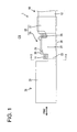
- a shown conduction path 1 is formed by connecting a front end portion (left end portion in FIGS. 1 and 2 ) of a wire 10 with a crimping portion 22 (as a preferred connecting structure) formed at or near a rear end portion of a terminal fitting 20.
- the wire 10 is comprised of a conductor 11 preferably formed by twisting a plurality of metal thin wires and an insulation coating 12 at least partly surrounding the conductor 11.
- the insulation coating 12 is at least partly removed as preparation for connection with the terminal fitting 20, whereby a front end portion of the conductor 11 is exposed.
- Copper or copper alloy, a material having higher rigidity than copper or copper alloy (e.g. aluminum or aluminum alloy) and/or a material having lower electrical conductivity than copper or copper alloy (e.g. aluminum or aluminum alloy) is or may be used as the material for the conductor 11.
- the terminal fitting 20 particularly is a female terminal fitting formed by applying bending, folding and/or embossing and the like to a conductive (preferably metal) plate material punched or cut out into a specified (predetermined or predeterminable) shape, wherein a front end region serves as a terminal connecting portion 21 particularly in the form of a (preferably substantially rectangular or polygonal) tube and a rear end region serves as a crimping portion 22 in the form of at least one open barrel.
- the terminal connecting portion 21 is of the known form that functions as connection means with a narrow and long tab (not shown) formed on a mating male terminal. It should be understood, however, that the present invention is also applicable to male terminal fittings having a substantially tab-shaped terminal connection portion connectable to a mating female terminal.
- the rear end of the terminal connecting portion 21 and the front end of the crimping portion 2 are coupled via at least one coupling portion 23.
- the coupling portion 23 preferably includes a lower or base plate and/or one or more, preferably a pair of laterally symmetrical side plates standing up or projecting at an angle different from 0° or 180°, preferably substantially at right angles from the (preferably substantially opposite) lateral (left and/or right) edge(s) of the lower plate, and an accommodation space 24 preferably with a substantially open upper side is formed in the coupling portion 23.
- the crimping portion 22 includes at least one wire barrel portion 25 substantially continuous with the rear end of the coupling portion 23 and/or at least one insulation barrel portion 31 located behind the wire barrel portion 25.
- the insulation barrel portion 31 is to be crimped or bent or folded into connection with a part of the front end portion of the wire 10 where the insulation coating 12 at least partly surrounding the conductor 11 is provided or still remains.
- an automatic machine (not shown) called an applicator is used and the insulation barrel portion 31 is crimped or bent or folded into connection with the wire 10 preferably substantially at the same time the wire barrel portion 25 is crimped or bent or folded into connection with the conductor 11.
- the wire 10 is pressed by being surrounded over at least part of the circumference, preferably over the substantially entire circumference by the insulation barrel portion 31 and the wire 10 is fixed to the insulation barrel portion 31 by a fixing force produced by this pressing.
- the wire barrel portion 25 includes a bottom or base wall 26 substantially continuous with the lower plate of the coupling portion 23 and one or more, preferably a pair of (preferably laterally symmetrical) crimping pieces 27 extending from the (preferably substantially opposite) lateral (left and/or right) edge(s) of the bottom wall 26.
- This wire barrel portion 25 is to be crimped or bent or folded into electrical connection with the conductor 11 at least partly exposed by removing the insulation coating 12 in or near the front end portion of the wire 11, whereby the conductor 11 particularly is fixed.
- a crimper (not shown) is lowered to deform the (pair of) crimping piece(s) 27 to wind it/them at least partly around the conductor 11 with the crimping portion 22 set in an anvil (not shown) of the automatic machine and the conductor 11 placed on the bottom wall 26.
- the bottom wall 26 and the pair of crimping pieces 27 are so crimped or bent or folded as to at least partly surround the conductor 11 while pressing it.
- the front end portion of the conductor 11 is located to project forward from the front end edge(s) of the crimping piece(s) 27 (wire barrel portion 25) and at least partly accommodated in the accommodation space 24 enclosed or defined by the lower or base plate and the opposite side plates of the coupling portion 23.
- the wire barrel portion 25 preferably is strongly fastened during the crimping operation to scrape off oxide films on the outer surfaces of the conductor (preferably of the metal thin wires).
- the metal thin wires constituting the conductor 11 particularly are or may be loosened and front end portions of the loosened metal thin wires are or may be deformed to spread out in the accommodation space 24 before the wire barrel portion 24.
- the accommodation space 24 is open upward (direction toward a side opposite to the bottom wall 26), some of the metal thin wires may be bent to be located above the wire barrel portion 25. If a part above the accommodation space 24 serves as a space to arrange another member (e.g. a retainer for retaining the terminal fitting 20 by being engaged with the rear end edge of the terminal connecting portion 21 when the terminal fitting 20 is at least partly inserted into an unillustrated housing), the bent-up metal thin wires may interfere with the other member. Furthermore, the outwardly projecting part of the conductor may also interfere with an outside member such as a housing upon being inserted thereinto.
- another member e.g. a retainer for retaining the terminal fitting 20 by being engaged with the rear end edge of the terminal connecting portion 21 when the terminal fitting 20 is at least partly inserted into an unillustrated housing
- the bent-up metal thin wires may interfere with the other member.
- the outwardly projecting part of the conductor may also interfere with an outside member such as a housing upon being inserted
- the wire barrel portion 25 is formed with one or more pressing portions 29 as means for preventing the front end portion of the conductor 11 (particularly metal thin wires) from being bent toward the upper side substantially opposite to the bottom wall 26.
- These pressing portions 29 are formed at or on one or more upper walls 28 (ceiling walls) of the crimping pieces 27 to be located at a side of the conductor 11 substantially opposite to the bottom wall 26 in the crimped state CS.
- the pressing portions 29 are preferably formed by hammering after the wire barrel portion 25 is crimped or bent or folded into connection with the conductor 11.
- the pair of lateral (left and right) crimping pieces 27 preferably are laterally symmetric and/or one pressing portion 29 is individually formed at each crimping piece 27.
- This pair of lateral (left and right) pressing portions 29 preferably are laterally symmetric.
- the pressing portions 29 preferably are formed from intermediate positions (preferably substantially central positions) of the crimping pieces 27 to the front ends of the crimping pieces 27 substantially in forward and backward directions FBD (longitudinal direction of the wire 10) and/or are inclined with respect to the bottom wall 26 to be sloped downward or inward toward the front. This angle of inclination preferably is substantially constant over the entire lengths of the pressing portions 29.
- Areas REA of the upper walls 28 of the crimping pieces 27 (rear end areas REA of the crimping pieces 27) behind or adjacent to the pressing portions 29 preferably are substantially parallel to the bottom wall 26.
- the pressing portions 29 preferably are formed substantially only in central parts of the crimping pieces 27 in a width direction WD (lateral direction).
- Left and right edge portions of the upper wall 28 of each crimping piece 27 serve as a pair of folded portions 30 to be located at the left and right sides of the pressing portion 29.
- the folded portions 30 preferably are such that folded parts face and project upward or outward or away from the conductor 11.
- the heights of the upper end edges of the folded portions 30 are substantially constant.
- the folded portions 30 are arranged at four positions spaced apart in the width direction WD, the inner two (i.e. standing end edge portions of the both crimping pieces 27) of these four folded portions 30 are so held in contact as to press each other in the width direction WD.
- the one or more pressing portions 29 closer to the bottom wall 26 than the rear end areas REA of the crimping pieces 27 preferably are formed at the front end portions of the upper walls 28 of the crimping pieces 27 located at the side of the conductor 11 substantially opposite to the bottom wall 26. Since the conductor 11 is displaced or deformed toward the bottom wall 26 by the pressing portions 29 at the front end portions of the upper walls 28 of the crimping pieces 27 in this way, the front end portion of the conductor 11 projecting from the front end of the wire barrel portion 25 has the height thereof from the bottom wall 26 suppressed low or reduced (e.g. as compared to a portion of the conductor 11 corresponding to the upper walls 28, see e.g. FIG. 4 ). Therefore, even if the front end portion of the conductor 11 is bent up toward the side opposite to the bottom wall 26, the height of the bent-up part is suppressed low or reduced.
- the front end portion of the conductor 11 also obliquely projects downward toward the front from the front end of the wire barrel portion 25 to approach the bottom wall 26 as can be seen from FIG. 4 .
- the height of the bent-up front end portion of the conductor 11 can be more effectively suppressed.
- the pressing portions 29 preferably are formed into recesses or channels preferably by hammering parts of the upper walls 28 of the crimping pieces 27 excluding the opposite widthwise end portions toward the bottom wall 26, and/or the (preferably substantially opposite) widthwise end portion(s) of the front end(s) of the upper wall(s) 28 preferably serve as the one or more folded portions 30 projecting toward the side substantially opposite to the bottom wall 26.
- the technical significance of this construction is as follows.
- the side walls connecting the upper walls 28 and the bottom wall 26 may be deformed outwardly in the width direction WD by as much as the approach amount of the upper walls 28 toward the bottom wall 26 and the wire barrel portion 25 may be widened.
- the folded portions 30 preferably are formed at the opposite widthwise ends of the upper walls 28 and/or only the parts between the folded portions 30 preferably are formed into the pressing portions 29 by being deformed to approach the bottom wall 26.
- a connection structure for a terminal fitting 20 including a wire barrel portion 25 in the form of at least one open barrel, in which one or more, preferably a pair of crimping pieces 27 stand up from a bottom wall 26, and a front end portion of a wire 10 including a conductor 11 (particularly formed by twisting a plurality of metal thin wires).
- the crimping pieces 27 compress the conductor 11 while at least partly surrounding it to electrically connect the conductor 11 and a front end portion of the conductor 11 projects forward from the front end of the wire barrel portion 25.
- One or more pressing portions 29 closer to the bottom wall 26 than rear end areas REA of the crimping pieces 27 are formed in front end portions of upper walls 28 of the crimping pieces 27 at a side of the conductor 11 substantially opposite to the bottom wall 26.
Landscapes
- Connections Effected By Soldering, Adhesion, Or Permanent Deformation (AREA)
Applications Claiming Priority (1)
| Application Number | Priority Date | Filing Date | Title |
|---|---|---|---|
| JP2008290199A JP2010118238A (ja) | 2008-11-12 | 2008-11-12 | 端子金具と電線の接続構造 |
Publications (1)
| Publication Number | Publication Date |
|---|---|
| EP2187478A1 true EP2187478A1 (de) | 2010-05-19 |
Family
ID=41137884
Family Applications (1)
| Application Number | Title | Priority Date | Filing Date |
|---|---|---|---|
| EP09011557A Withdrawn EP2187478A1 (de) | 2008-11-12 | 2009-09-09 | Anschlussstück, Drahtverbindungsstruktur und Verbindungsverfahren |
Country Status (4)
| Country | Link |
|---|---|
| US (1) | US20100120298A1 (de) |
| EP (1) | EP2187478A1 (de) |
| JP (1) | JP2010118238A (de) |
| CN (1) | CN101740881A (de) |
Families Citing this family (2)
| Publication number | Priority date | Publication date | Assignee | Title |
|---|---|---|---|---|
| DE102017105682A1 (de) * | 2017-03-16 | 2018-09-20 | Te Connectivity Germany Gmbh | Kontaktträger, elektrische Kontakteinrichtung sowie Verfahren zum Herstellen eines konfektionierten Kabels |
| FR3065330B1 (fr) * | 2017-04-13 | 2019-05-03 | Tyco Electronics France Sas | Outil pour souder un conducteur electrique avec un dispositif de connexion |
Citations (7)
| Publication number | Priority date | Publication date | Assignee | Title |
|---|---|---|---|---|
| US2596528A (en) * | 1949-10-25 | 1952-05-13 | Aircraft Marine Prod Inc | Electrical connector having coaxial barrels of different diameters |
| US20040142607A1 (en) * | 2002-12-11 | 2004-07-22 | Yazaki Corporation | Method of connecting and structure of connecting electric wire and connection terminal |
| JP2005222815A (ja) | 2004-02-05 | 2005-08-18 | Sumitomo Wiring Syst Ltd | 端子金具及びコネクタ |
| WO2007043345A1 (ja) * | 2005-09-30 | 2007-04-19 | Autonetworks Technologies, Ltd. | 端子付き電線の製造方法及び端子付き電線並びに端子圧着装置 |
| DE102006045567A1 (de) * | 2006-09-25 | 2008-04-24 | Tyco Electronics Amp Gmbh | Crimpstabilisierung |
| FR2928039A1 (fr) * | 2008-02-25 | 2009-08-28 | Leoni Wiring Systems France Sa | Assemblage formant liaison electrique par sertissage. |
| WO2009115860A1 (en) * | 2008-03-20 | 2009-09-24 | Fci | Electric terminal crimping method and assembly obtained |
Family Cites Families (5)
| Publication number | Priority date | Publication date | Assignee | Title |
|---|---|---|---|---|
| US2692422A (en) * | 1948-03-10 | 1954-10-26 | Aircraft Marine Prod Inc | Method of applying connectors |
| US2806214A (en) * | 1953-04-07 | 1957-09-10 | Amp Inc | Pre-insulated connector and method of making the same |
| BE549349A (de) * | 1955-07-07 | |||
| US4953289A (en) * | 1989-06-05 | 1990-09-04 | Pyle Overseas B.V. | Conductor terminating method |
| JP3868234B2 (ja) * | 2001-07-13 | 2007-01-17 | 矢崎総業株式会社 | 圧着端子 |
-
2008
- 2008-11-12 JP JP2008290199A patent/JP2010118238A/ja active Pending
-
2009
- 2009-09-09 EP EP09011557A patent/EP2187478A1/de not_active Withdrawn
- 2009-10-15 CN CN200910206373A patent/CN101740881A/zh active Pending
- 2009-11-05 US US12/613,127 patent/US20100120298A1/en not_active Abandoned
Patent Citations (7)
| Publication number | Priority date | Publication date | Assignee | Title |
|---|---|---|---|---|
| US2596528A (en) * | 1949-10-25 | 1952-05-13 | Aircraft Marine Prod Inc | Electrical connector having coaxial barrels of different diameters |
| US20040142607A1 (en) * | 2002-12-11 | 2004-07-22 | Yazaki Corporation | Method of connecting and structure of connecting electric wire and connection terminal |
| JP2005222815A (ja) | 2004-02-05 | 2005-08-18 | Sumitomo Wiring Syst Ltd | 端子金具及びコネクタ |
| WO2007043345A1 (ja) * | 2005-09-30 | 2007-04-19 | Autonetworks Technologies, Ltd. | 端子付き電線の製造方法及び端子付き電線並びに端子圧着装置 |
| DE102006045567A1 (de) * | 2006-09-25 | 2008-04-24 | Tyco Electronics Amp Gmbh | Crimpstabilisierung |
| FR2928039A1 (fr) * | 2008-02-25 | 2009-08-28 | Leoni Wiring Systems France Sa | Assemblage formant liaison electrique par sertissage. |
| WO2009115860A1 (en) * | 2008-03-20 | 2009-09-24 | Fci | Electric terminal crimping method and assembly obtained |
Also Published As
| Publication number | Publication date |
|---|---|
| US20100120298A1 (en) | 2010-05-13 |
| JP2010118238A (ja) | 2010-05-27 |
| CN101740881A (zh) | 2010-06-16 |
Similar Documents
| Publication | Publication Date | Title |
|---|---|---|
| US7828611B2 (en) | Terminal fitting | |
| US8251759B2 (en) | Terminal fitting, a terminal fitting chain, a wire with a terminal fitting and a processing device therefor | |
| EP2151892B1 (de) | Anschlussstück und Anschlussverfahren dafür | |
| US7901257B2 (en) | Terminal fitting | |
| JP5394713B2 (ja) | 圧着端子 | |
| EP2110901A1 (de) | Anschluss-crimpverfahren, anschluss-crimpstruktur, anschluss-crimpeinrichtung und elektrischer verbinder | |
| EP1742300B1 (de) | Anschlusskontakt und Herstellungsverfahren dafür | |
| US7402089B1 (en) | Contact with enhanced transition region | |
| EP1981123A2 (de) | Anschlussstück und Crimp-Verfahren dafür | |
| EP2157669A1 (de) | Steckverbinder und Montageverfahren dafür | |
| JP2009152110A (ja) | 圧着構造及び圧着方法 | |
| US8523619B2 (en) | Terminal fitting | |
| EP2485334A1 (de) | Mehrfacher Anschlusskontakt | |
| EP2375512B1 (de) | Anschlussstück und Verfahren zu dessen Herstellung | |
| US20100035487A1 (en) | Terminal fitting and a wire connected with a terminal fitting | |
| EP2159880A1 (de) | Anschlussstück und an dem Anschlussstück angeschlossener Draht | |
| US20220231434A1 (en) | Terminal and terminal wire assembly | |
| EP2187478A1 (de) | Anschlussstück, Drahtverbindungsstruktur und Verbindungsverfahren | |
| JP5132397B2 (ja) | 端子金具、及びワイヤーハーネス | |
| JP2010040456A (ja) | 端子金具及びワイヤーハーネス | |
| JP2010010000A (ja) | 端子金具及び端子付き電線 | |
| WO2012017807A1 (ja) | 圧着端子 | |
| EP1811608B1 (de) | Anschlussstück und Stecker dafür | |
| JP5506028B2 (ja) | 圧着装置 | |
| US7789715B2 (en) | Terminal fitting with posture correcting edge and inclination restricting portion and a connector provided therewith |
Legal Events
| Date | Code | Title | Description |
|---|---|---|---|
| PUAI | Public reference made under article 153(3) epc to a published international application that has entered the european phase |
Free format text: ORIGINAL CODE: 0009012 |
|
| 17P | Request for examination filed |
Effective date: 20090917 |
|
| AK | Designated contracting states |
Kind code of ref document: A1 Designated state(s): AT BE BG CH CY CZ DE DK EE ES FI FR GB GR HR HU IE IS IT LI LT LU LV MC MK MT NL NO PL PT RO SE SI SK SM TR |
|
| AX | Request for extension of the european patent |
Extension state: AL BA RS |
|
| 17Q | First examination report despatched |
Effective date: 20100712 |
|
| STAA | Information on the status of an ep patent application or granted ep patent |
Free format text: STATUS: THE APPLICATION IS DEEMED TO BE WITHDRAWN |
|
| 18D | Application deemed to be withdrawn |
Effective date: 20101123 |