EP2187012A2 - Système de purification de gaz d'échappement pour machine d'ingénierie - Google Patents
Système de purification de gaz d'échappement pour machine d'ingénierie Download PDFInfo
- Publication number
- EP2187012A2 EP2187012A2 EP09014009A EP09014009A EP2187012A2 EP 2187012 A2 EP2187012 A2 EP 2187012A2 EP 09014009 A EP09014009 A EP 09014009A EP 09014009 A EP09014009 A EP 09014009A EP 2187012 A2 EP2187012 A2 EP 2187012A2
- Authority
- EP
- European Patent Office
- Prior art keywords
- engineering machine
- work pause
- work
- time
- filter
- Prior art date
- Legal status (The legal status is an assumption and is not a legal conclusion. Google has not performed a legal analysis and makes no representation as to the accuracy of the status listed.)
- Granted
Links
Images


Classifications
-
- F—MECHANICAL ENGINEERING; LIGHTING; HEATING; WEAPONS; BLASTING
- F01—MACHINES OR ENGINES IN GENERAL; ENGINE PLANTS IN GENERAL; STEAM ENGINES
- F01N—GAS-FLOW SILENCERS OR EXHAUST APPARATUS FOR MACHINES OR ENGINES IN GENERAL; GAS-FLOW SILENCERS OR EXHAUST APPARATUS FOR INTERNAL COMBUSTION ENGINES
- F01N3/00—Exhaust or silencing apparatus having means for purifying, rendering innocuous, or otherwise treating exhaust
- F01N3/02—Exhaust or silencing apparatus having means for purifying, rendering innocuous, or otherwise treating exhaust for cooling, or for removing solid constituents of, exhaust
- F01N3/021—Exhaust or silencing apparatus having means for purifying, rendering innocuous, or otherwise treating exhaust for cooling, or for removing solid constituents of, exhaust by means of filters
- F01N3/023—Exhaust or silencing apparatus having means for purifying, rendering innocuous, or otherwise treating exhaust for cooling, or for removing solid constituents of, exhaust by means of filters using means for regenerating the filters, e.g. by burning trapped particles
-
- E—FIXED CONSTRUCTIONS
- E02—HYDRAULIC ENGINEERING; FOUNDATIONS; SOIL SHIFTING
- E02F—DREDGING; SOIL-SHIFTING
- E02F9/00—Component parts of dredgers or soil-shifting machines, not restricted to one of the kinds covered by groups E02F3/00 - E02F7/00
- E02F9/08—Superstructures; Supports for superstructures
- E02F9/0858—Arrangement of component parts installed on superstructures not otherwise provided for, e.g. electric components, fenders, air-conditioning units
- E02F9/0866—Engine compartment, e.g. heat exchangers, exhaust filters, cooling devices, silencers, mufflers, position of hydraulic pumps in the engine compartment
-
- B—PERFORMING OPERATIONS; TRANSPORTING
- B01—PHYSICAL OR CHEMICAL PROCESSES OR APPARATUS IN GENERAL
- B01D—SEPARATION
- B01D53/00—Separation of gases or vapours; Recovering vapours of volatile solvents from gases; Chemical or biological purification of waste gases, e.g. engine exhaust gases, smoke, fumes, flue gases, aerosols
- B01D53/34—Chemical or biological purification of waste gases
- B01D53/92—Chemical or biological purification of waste gases of engine exhaust gases
-
- E—FIXED CONSTRUCTIONS
- E02—HYDRAULIC ENGINEERING; FOUNDATIONS; SOIL SHIFTING
- E02F—DREDGING; SOIL-SHIFTING
- E02F9/00—Component parts of dredgers or soil-shifting machines, not restricted to one of the kinds covered by groups E02F3/00 - E02F7/00
-
- F—MECHANICAL ENGINEERING; LIGHTING; HEATING; WEAPONS; BLASTING
- F01—MACHINES OR ENGINES IN GENERAL; ENGINE PLANTS IN GENERAL; STEAM ENGINES
- F01N—GAS-FLOW SILENCERS OR EXHAUST APPARATUS FOR MACHINES OR ENGINES IN GENERAL; GAS-FLOW SILENCERS OR EXHAUST APPARATUS FOR INTERNAL COMBUSTION ENGINES
- F01N9/00—Electrical control of exhaust gas treating apparatus
- F01N9/002—Electrical control of exhaust gas treating apparatus of filter regeneration, e.g. detection of clogging
-
- F—MECHANICAL ENGINEERING; LIGHTING; HEATING; WEAPONS; BLASTING
- F02—COMBUSTION ENGINES; HOT-GAS OR COMBUSTION-PRODUCT ENGINE PLANTS
- F02M—SUPPLYING COMBUSTION ENGINES IN GENERAL WITH COMBUSTIBLE MIXTURES OR CONSTITUENTS THEREOF
- F02M35/00—Combustion-air cleaners, air intakes, intake silencers, or induction systems specially adapted for, or arranged on, internal-combustion engines
- F02M35/02—Air cleaners
-
- Y—GENERAL TAGGING OF NEW TECHNOLOGICAL DEVELOPMENTS; GENERAL TAGGING OF CROSS-SECTIONAL TECHNOLOGIES SPANNING OVER SEVERAL SECTIONS OF THE IPC; TECHNICAL SUBJECTS COVERED BY FORMER USPC CROSS-REFERENCE ART COLLECTIONS [XRACs] AND DIGESTS
- Y02—TECHNOLOGIES OR APPLICATIONS FOR MITIGATION OR ADAPTATION AGAINST CLIMATE CHANGE
- Y02T—CLIMATE CHANGE MITIGATION TECHNOLOGIES RELATED TO TRANSPORTATION
- Y02T10/00—Road transport of goods or passengers
- Y02T10/10—Internal combustion engine [ICE] based vehicles
- Y02T10/40—Engine management systems
Definitions
- the present invention relates generally to exhaust gas purification systems for engineering machines. More particularly, the invention concerns an exhaust gas purification system for engineering machines of a traveling type, such as hydraulic excavators, each of the machines including a regenerating device to burn off a deposit of particulate matter from a filter disposed for trapping the particulate matter contained in gas emissions, and regenerate the filter.
- a traveling type such as hydraulic excavators
- each of the machines including a regenerating device to burn off a deposit of particulate matter from a filter disposed for trapping the particulate matter contained in gas emissions, and regenerate the filter.
- Conventional exhaust gas purification systems for purifying diesel engine gas emissions include the systems described in JP,A 2005-120895 and JP-3073380 , for example.
- the exhaust gas purification system described in JP,A 2005-120895 has a filter, called a diesel particulate filter (DPF), in the engine exhaust line of a truck or any other transport vehicle to trap the particulate matter (PM) contained in gas emissions and reduce the amount of PM released to the outside.
- DPF diesel particulate filter
- the purification system in JP,A 2005-120895 is also adapted to conduct automatic regeneration control and manual regeneration control.
- Automatic regeneration control detects the differential pressure across the filter, then discriminates the estimated amount of PM deposited thereupon, and if this estimated amount of PM exceeds a first threshold level, increases the temperature of the gas emissions automatically to burn off the PM from the filter.
- Manual regeneration control which, if the estimated amount of PM exceeds a second threshold level greater than the first threshold level, prompts an operator to start manual regeneration control under a stopped state of the vehicle by activating a warning lamp, and when the operator turns on a manual regenerating switch, increases the temperature of the gas emissions to burn off the PM deposited on the filter.
- the temperature of the gas emissions is increased by the oxidation of unburnt hydrocarbons (HC) due to additional fuel injection during the expansion stroke of the engine after main injection.
- the exhaust gas purification system described in JP-3073380 regenerates a filter in a hydraulic engineering machine by burning off deposits from the filter after engine output has been enhanced by loading the engine in a hydraulic-like manner for an increased gas emissions temperature.
- the purification system in JP-3073380 the exhaust resistance of the engine due to the use of the filter and start the regeneration of the filter automatically if the exhaust resistance exceeds a permissible level.
- the exhaust gas purification systems in trucks and other transport vehicles provide two control techniques relating to the regeneration of the filter in the purification system.
- One is automatic regeneration control, which is conducted during vehicle traveling
- the other is manual regeneration control, which is conducted under the stopped state of the vehicle body. If the PM deposited on the filter cannot be burned off with automatic regeneration control and the amount of PM continues increasing, manual regeneration control is usually used to remove the PM by burning.
- manual regeneration control since automatic regeneration control is conducted during vehicle traveling, the amount of PM deposited on the filter during engine operation may increase above the amount of PM burn-off by regeneration, and if this actually happens, the amount of PM deposited will increase, even after the regeneration with automatic regeneration control.
- Manual regeneration control allows reliable burn-off of the PM deposited on the filter, since the temperature of the gas emissions is increased by additional fuel injection or the like under the stopped state of the vehicle body to burn off the deposited PM from the filter.
- An object of the present invention is to provide an exhaust gas purification system for an engineering machine, adapted to avoid decreases in working efficiency by burning off a deposit of particulate matter on a filter efficiently during a work pause time of the engineering machine.
- the work pause time can be set automatically.
- the amount of particulate matter deposited on the filter can be reduced efficiently by burning the deposited particulate matter during the work pause time of the engineering machine, and a decrease in working efficiency can be avoided by the regeneration control.
- the regeneration control that utilizes the work pause time can be conducted without deteriorating engine fuel efficiency.
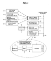
- Fig. 1 is a diagram showing an exhaust gas purification system for a hydraulic excavator (engineering machine) according to a first embodiment of the present invention.
- reference number 1 denotes a diesel engine (hereinafter, referred to simply as the engine).
- the engine 1 includes an exhaust pipe 2 that discharges gas emissions to the outside, and a muffler 3 is connected to a distal end of the exhaust pipe 2.
- the engine 1 has its speed and its torque controlled by an engine control unit 4.
- the engine control unit 4 receives an input signal indicating a target engine speed specified using an engine control knob, and then on the basis of the target engine speed and an actual engine speed detected by an engine speed detection sensor, controls an electronic governor equipped on the engine 1, and controls a fuel injection rate. The speed and torque of the engine 1 are thus controlled.
- the engine control unit 4 is connected to a vehicle body control unit 21, an information storage unit 22, and a monitor control unit 23, via a communication line 25, thus constituting a vehicle body network.
- the vehicle body control unit 21 receives input signals from sensors provided in a hydraulic system (described later) and on the vehicle body, and conducts arithmetic processing for hydraulic control and vehicle body control.
- the monitor control unit 23 receives detection signals from various sensors not shown, such as a residual fuel amount sensor and water temperature sensor that the engine control unit 4 and the vehicle body control unit 21 have, via the communication line 25.
- the monitor control unit 23 also undertakes display control to display detection results at a display monitor 16.
- the monitor control unit 23 further controls data entry that uses an operating section 17 of the display monitor 16.
- the information storage unit 22 collects various input signals as operational data from the engine control unit 4, the vehicle body control unit 21, the monitor control unit 23, and the like, via the communication line 25, and stores the data into a database chronologically. Also, the data is periodically transmitted to a management server using a satellite communication terminal not shown.
- the exhaust gas purification system of the present embodiment provided in the hydraulic excavator including the above-described units and devices, includes a diesel particulate filter (DPF) unit 11 disposed in the exhaust pipe 2 that forms part of an exhaust system of the engine 1.
- the filter unit 11 traps particulate matter (PM) contained in gas emissions.
- the exhaust gas purification system also includes a differential pressure sensor 12 that detects a difference in pressure between an upstream side and downstream side of the filter unit 11, that is, a pressure drop in the filter unit 11.
- the exhaust gas purification system includes a work pause switch 13 (first operating unit) operated by an operator to notify that the hydraulic excavator has entered a work pause state.
- the exhaust gas purification system includes a pressure sensor 14 for detecting whether control pilot pressures of remote control valves (described later) are present, the sensor 14 also being used to detect active and inactive states of operating elements pertaining to engineering work.
- the exhaust gas purification system includes a solenoid control valve 15 for imparting a hydraulic load to the engine 1 during regeneration control.
- the exhaust gas purification system includes the operating section 17 of the display monitor 16 that functions as a second operating unit for the operator to enter a work pause time.
- the exhaust gas purification system includes the vehicle body control unit 21, the monitor control unit 23, and the engine control unit 4.
- the filter unit 11 contains a filter formed to trap the PM contained in the gas emissions, and an oxidation catalyst disposed at an upstream side of the filter.
- the engine control unit 4 receives a detection signal as an input signal from the differential pressure sensor 12, and transmits the detection signal to the vehicle body control unit 21 via the communication line 25.
- the monitor control unit 23 receives the entered work pause time and then transmits the received work pause time to the vehicle body control unit 21 via the communication line 25.
- the vehicle body control unit 21 Upon receiving the work pause time from the monitor control unit 23 via the communication line 25, the vehicle body control unit 21 stores the received work pause time into a storage unit such as a hard disk, and sets the stored work pause time as a regeneration control time. In addition, the vehicle body control unit 21 receives the detection signal of the differential pressure sensor 12, transmitted from the engine control unit 4. The vehicle body control unit 21 further receives an operating signal created by the work pause switch 13, and a detection signal created by the pressure sensor 14. The vehicle body control unit 21 uses the received signals to conduct predetermined arithmetic processing, output a regeneration starting instruction signal and a regeneration stopping instruction signal to the engine control unit 4 via the communication line 25, and output an ON control signal to the solenoid control valve 15.
- the engine control unit 4 has a regeneration controller 4a that functions as a regenerating device.
- the engine control unit 4 upon receiving the regeneration starting instruction signal from the vehicle body control unit 21, activates the regeneration controller 4a, and upon receiving the regeneration stopping instruction signal from the vehicle body control unit 21, deactivates the regeneration controller 4a.
- the regeneration controller 4a conducts regeneration control by controlling the electronic governor of the engine 1.
- the regeneration controller 4a maintains the engine speed at a predetermined speed (say, 1,750 rpm) and oxidizes unburnt HC (hydrocarbons) by post-injection (additional fuel injection) in an expansion stroke of the engine after main fuel injection.
- a predetermined speed say, 1,750 rpm
- the oxidation of the HC then raises a temperature of the gas emissions.
- the heated emissions activate the oxidation catalyst of the filter unit 11, thereby burning off the PM deposited on the filter.
- the exhaust gas purification system has a manual regeneration starting switch 18, and the vehicle body control unit 21 receives an operating signal of the manual regeneration starting switch 18 and after conducting a predetermined arithmetic process, outputs a regeneration starting signal and a regeneration stopping signal to the engine control unit 4 via the communication line 25.
- the vehicle body control unit 21 further outputs a control signal to the solenoid control valve 15.
- the engine control unit 4 also activates the regeneration controller 4a upon receiving the regeneration starting signal, and deactivates the regeneration controller 4a upon receiving the regeneration stopping signal.
- the regeneration control based upon the operating signal of the work pause switch 13 is referred to as work pause time-based regeneration control, and the regeneration control based upon the operating signal of the manual regeneration starting switch 18 is referred to as manual regeneration control.
- operation of the regeneration controller 4a (regenerating device) is also referred to as regeneration control.
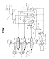
- Fig. 2 is a diagram showing a hydraulic circuit system mounted in the hydraulic excavator, the engineering machine according to the present embodiment.
- the hydraulic circuit system of the hydraulic excavator includes a variable-displacement type of main hydraulic pump 31 and a fixed-displacement type of pilot pump 32, both driven by the engine 1.
- the hydraulic circuit system also has a plurality of hydraulic actuators including a hydraulic motor 33 and hydraulic cylinders 34, 35 driven by a hydraulic fluid delivered from the hydraulic pump 31, and a plurality of flow control valves including pilot-operated flow control valves 37 to 39 each for controlling a flow (flow rate and direction) of the hydraulic fluid supplied from the hydraulic pump 31 to the hydraulic motor 33 and the hydraulic cylinders 34, 35.
- the hydraulic circuit system further has a solenoid control valve 43 connected to a downstream side of the pilot hydraulic fluid source 40, the solenoid control valve 43 being ON/OFF controlled according to an open/closed state of a gate lock lever provided at an entrance side of a cabin of the hydraulic excavator.
- the hydraulic circuit system has remote control valves 45, 46, and 47 connected to a pilot hydraulic line 44 at a downstream side of the solenoid control valve 43 and used to generate control pilot pressures "a" to "f” for operating the flow control valves 37 to 39 with an hydraulic pressure of the pilot hydraulic fluid source 40 as a main pressure.
- the hydraulic circuit system has a main relief valve 48 that functions as a safety device to define a maximum allowable delivery pressure of the main hydraulic pump 31.
- the remote control valves 45, 46, and 47 are contained in left and right control levers positioned to the left and right of an operator's seat within the cabin.
- pilot lines 45a/45b, 46a/46b, and 47a/47b Primary ports of the remote control valves 45, 46, and 47 are connected to the pilot hydraulic line 44, secondary ports are connected to pilot lines 45a/45b, 46a/46b, and 47a/47b, and the control pilot pressures "a" to "f", after being generated by the remote control valves 45, 46, and 47, are guided to pressure-receiving sections of the flow control valves 37 to 39 through the pilot lines.
- the pilot lines 45a/45b, 46a/46b, and 47a/47b have a shuttle valve group 50 connected to each.
- the shuttle valve group 50 includes shuttle valves 50a to 50f, with the shuttle valve 50a being connected between the pilot lines 45a and 45b of the remote control valve 45, the shuttle valve 50b being connected between the pilot lines 46a and 46b of the remote control valve 46, the shuttle valve 50c being connected between the pilot lines 47a and 47b of the remote control valve 47, the shuttle valve 50d being connected between output ports of the shuttle valves 50a and 50b, the shuttle valve 50e being connected between output ports of the shuttle valves 50c and 50d, and the shuttle valve 50f being connected between an output port of the shuttle valve 50e and an output port of a final-stage shuttle valve pertaining to a remote control valve of any other operating element (not shown).
- the shuttle valve group 50 including the shuttle valves 50a to 50f extracts a maximum pressure of all control pilot pressures, which include the control pilot pressures "a" to "f" of the remote control valves 45 to 47 and the control pilot pressures of the remote control valves of other operating elements not shown.
- the final-stage shuttle valve 50f in the shuttle valve group 50 outputs the maximum pressure.
- the pressure sensor 14 thereby detects the control pilot pressures of all remote control valves including the remote control valves 45 to 47, that is, the active/inactive states of the work-associated operating elements including the control levers of the remote control valves 45 to 47.
- the plurality of flow control valves including the flow control valves 37 to 39 are center-bypass valves, which are each connected in series to a center-bypass line 51 that connects to the delivery hydraulic line of the hydraulic pump 31, the center-bypass line 51 being connected at its downstream extreme end 51a to a tank T. Also, the solenoid control valve 15 is connected to the downstream extreme end 51a of the center-bypass line 51.
- the solenoid control valve 15 is a two-position control valve having an open position and a closed position.
- the control valve 15 When the ON control signal from the vehicle body control unit 21 is absent and the solenoid control valve 15 does not have its solenoid energized, the control valve 15 is placed in the open position, and when the ON control signal is output from the vehicle body control unit 21 and the solenoid is energized, the control valve 15 is switched from the open position shown in the figure, to the closed position.
- the solenoid control valve 15 is switched to the closed position when the engine control unit 4 activates the regenerating device (regeneration controller 4a).
- the solenoid control valve 15 is switched to the closed position, the delivery pressure of the hydraulic pump 31 will increase to a pressure setting of the main relief valve 48. Consequently, the engine 1 that drives the hydraulic pump 31 will also increase in load torque. This will allow the exhaust gas temperature of the engine 1 to be increased along with the activation of the regenerating device (regeneration control).
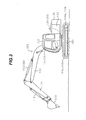
- Fig. 3 is an external view of the hydraulic excavator, an example of an engineering machine equipped with the hydraulic circuit system shown in Fig. 2 .
- the hydraulic excavator includes a lower travel structure 100, an upper swing structure 101, and a front work device 102.
- the lower travel structure 100 has left and right crawler-driven travel devices 103a, 103b, and is driven by left and right traveling motors 104a, 104b.
- the upper swing structure 101 is mounted on the lower travel structure 100 so as to be swingable by a swing motor 105.
- the front work device 102 is installed on a forepart of the upper swing structure 101 so as to be vertically inclinable.
- the upper swing structure 101 includes an engine room 106 and the cabin 107.
- the engine 1 is disposed in the engine room 106, the gate lock lever is provided at an entrance side of the operator's seat inside the cabin 107, and the control levers containing the remote control valves 35, 36, and 37 are arranged across the operator's seat. Also, the engine control knob and the display monitor 16 are appropriately positioned in the cabin 107.
- the front work device 102 is a multi-articulated structure with a boom 111, an arm 112, and a bucket 113.
- the boom 111 is turned vertically by extension/contraction of a boom cylinder 114
- the arm 112 is turned vertically and/or longitudinally by extension/contraction of an arm cylinder 115
- the bucket 113 is turned vertically and/or longitudinally by extension/contraction of a bucket cylinder 116.
- the hydraulic motor 33 is, for example, the swing motor 105
- the hydraulic cylinder 34 is, for example, the arm cylinder 115
- the hydraulic cylinder 35 is, for example, the boom cylinder 114.
- Other hydraulic actuators equivalent to the traveling motors 104a, 104b, the bucket cylinder 116, and the like, are also actually included in the hydraulic circuit system of Fig. 2 , but these actuators are omitted therefrom. This also applies to other control valves.
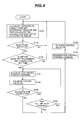
- Fig. 4 is a flowchart that shows process details of the work pause time-based regeneration control with the vehicle body control unit 21.
- the vehicle body control unit 21 executes the arithmetic process shown in Fig. 4 , in a predetermined control cycle.
- the vehicle body control unit 21 receives the detection signal of the differential pressure sensor 12, transmitted from the engine control unit 4, then calculates a current deposition level of the particulate matter deposited on the filter of the filter unit 11, from the differential pressure detected across the filter unit 11 by the differential pressure sensor 12, and further calculates from the above-calculated deposition level a time required for the regenerating device to burn off the deposited PM.
- the thus-calculated deposition level is referred to as the deposited PM amount, the differential pressure as the DPF differential pressure, and the necessary burn-off time as the regenerating requirement time.
- the calculation of the deposited PM amount is conducted by storing into a memory table such a relationship of the DPF differential pressure and deposited PM amount as shown in Fig. 5 , then checking the DPF differential pressure, detected by the differential pressure sensor 12, against the memory table, and deriving the deposited PM amount corresponding to the DPF differential pressure. As shown in Fig. 5 , the relationship that the deposited PM amount increases with increases in the DPF differential pressure is set in the memory table. This relationship between the deposited PM amount and the DPF differential pressure is derived by experimentation or the like beforehand.
- the calculation of the regenerating requirement time is conducted by storing into the memory table such a relationship of the deposited PM amount and regenerating requirement time as shown in Fig. 6 , then checking the calculated PM deposition level against the memory table, and deriving the appropriate regenerating requirement time. As shown in Fig. 6 , the relationship that the regenerating requirement time increases with increases in the deposited PM amount is set in the memory table. This relationship between the deposited PM amount and the regenerating requirement time is derived by experimentation or the like beforehand.
- step S110 whether the work pause switch 13 has been operated, that is, whether the switch 13 has turned on, is judged from the operating signal level of the work pause switch 13 (step S110). This judgment is further followed by a judgment as to whether the regenerating requirement time that was calculated in step S100 is in excess of the work pause time entered and set using the operating section 17 of the monitor control unit 23 (step S120). If the state of the work pause switch 13 is ON and the regenerating requirement time is in excess of the set work pause time, the regeneration control starting signal is output to the engine control unit 4 (step S130). In addition, the control ON signal is output to the solenoid control valve 15 to switch this valve to the closed position (step S140). This starts the regeneration control with the engine 1 loaded in a hydraulic fashion.
- step S110 If the state of the work pause switch 13 in step S110 is not ON or if the regenerating requirement time in step S120 is not in excess of the set work pause time, process control is returned to step S100 to repeat process steps S100 and S110.
- step S150 whether the work pause state is continued is judged (step S150) and whether an elapsed time from the activation (ON state) of the work pause switch 13 has exceeded the set work pause time is judged (step S160).
- the judgment as to whether the work pause state is continued is conducted by control pilot pressure detection of all remote control valves including the remote control valves 45 to 47, the detection being based upon the detection signal from the pressure sensor 14. In other words, if no control pilot pressure is detected, the work pause state is judged to be continued, or if a control pilot pressure is detected, the work is judged to have been started. If the work pause state is continued and the elapsed time from the activation of the work pause switch 13 is not in excess of the set time, process control is returned to step S130 to repeat process steps S130 to S160.
- step S150 If it is judged in step S150 that the work has been started, or if it is judged in step S160 that the elapsed time from the activation of the work pause switch 13 has exceeded the set work pause time, the regeneration control stopping signal is output to the engine control unit 4 (step S170). In addition, the control signal to be output to the solenoid control valve 15 is turned off to switch this valve to the open position (step S180). This releases the hydraulic load of the engine 1 and stops the regeneration control.
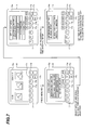
- Fig. 7 is a diagram showing a configuration of the operating section 17 of the display monitor 16 and an entry procedure relating to the work pause time.
- the display monitor 16 has a display panel 16a of a liquid crystal type or the like, and the operating section 17 is made up of a switch group disposed at a lower side of the display panel 16a, the switch group including F4 to F7 switches 17a to 17d and a menu switch 17e.
- a hydraulic working fluid temperature, an in-radiator coolant temperature, an engine fuel level, and other data measurements are normally displayed on the display panel 16a of the display monitor 16.
- a press of the menu switch 17e under this state changes the display to a menu. Items that can be selected from the menu include a "DPF function".
- the F4 switch 17a and the F5 switch 17b function as vertical cursor control keys to move vertically a cursor (shaded section in Fig. 7 ) that is displayed in the menu mode.
- the F6 switch 17c functions as an acknowledge key
- the F7 switch 17d as a return key.
- the operator For entry of the work pause time, the operator selects the "DPF function" by operating the F4 switch 17a and the F5 switch 17b, namely, the vertical cursor control keys, and then presses the F6 switch 17c, namely the acknowledge key, to acknowledge the selection.
- the press of the acknowledge key 17c changes the display to a DPF select menu. Items that can be selected from the DPF select menu include "DPF regenerating time interval setup". In this menu mode, the operator selects "DPF regenerating time interval setup" by operating the F4 switch 17a and the F5 switch 17b, namely, the vertical cursor control keys, and then presses the F6 switch 17c, or the acknowledge key, to acknowledge the selection.
- the press of the acknowledge key 17c changes the display mode to DPF regenerating time interval setup.
- a region for entering data in "Vehicle body pause time interval” is displayed in the DPF regenerating time interval setup mode.
- the F4 switch 17a and the F5 switch 17b function as a data-incrementing key and a data-decrementing key, respectively.
- the operator enters a value in the " Vehicle body pause time interval" display region by operating the incrementing and decrementing keys 17a, 17b, and then presses the F6 switch 17c, or the acknowledge key, to acknowledge the entry.
- the press of the acknowledge key 17c causes the entered value to be transmitted as a work pause time setup signal from the monitor control unit 23 through the communication line 25 to the vehicle body control unit 21, in which the value is then set.
- Fig. 8 is a flowchart that shows process details of the manual regeneration control with the vehicle body control unit 21.
- the vehicle body control unit 21 executes the arithmetic process shown in Fig. 8 , in a predetermined control cycle.
- step S200 the vehicle body control unit 21 receives as an input signal the detection signal of the differential pressure sensor 12, transmitted from the engine control unit 4, and judges whether the differential pressure across the filter unit 11, detected by the differential pressure sensor 12, is greater than a preset regeneration-starting threshold level ⁇ PUL. If judgment results are YES, a warning that prompts the operator to start the manual regeneration control is displayed on the display monitor 16 (step S210). Process step S200 is repeated if the judgment results are NO.
- the regeneration-starting threshold level ⁇ PUL here is a limit value for preventing thermal damage to the filter of the filter unit 11.
- step S210 After the execution of step S210 to display the warning that prompts the operator to start the manual regeneration control on the display monitor 16, a judgment as to whether the manual regeneration starting switch 18 has been operated (i.e., turned on) is conducted in step S220. If judgment results are NO, the process is repeated. If the judgment results are YES, the regeneration control starting signal is output to the engine control unit 4 (step S230) and then the control ON signal is output to the solenoid control valve 15 to switch this valve to the closed position (step S240). This starts the regeneration control of the engine control unit 4 with the engine 1 loaded in a hydraulic fashion.
- step S250 it is judged in step S250 whether the differential pressure across the filter unit 11, detected by the differential pressure sensor 12, is smaller than a preset regeneration-ending threshold level ⁇ PDL. If judgment results are NO, the process is repeated. If the judgment results are YES, the regeneration control stopping signal is output to the engine control unit 4 (step S260) and then the control signal to be output to the solenoid control valve 15 is turned off to switch this valve to the open position (step S270). This releases the hydraulic load of the engine 1 and stops the regeneration control of the engine control unit 4.
- the operating section 17 of the display monitor 16 when the operating section 17 of the display monitor 16 functions as an operating unit for entering the work pause time, the operating section 17 constitutes a setting element that presets the work pause time for the engineering machine (hydraulic excavator).
- the work pause switch 13 constitutes an element for notifying that the engineering machine (hydraulic excavator) has entered the work pause state.
- the processing function of the vehicle body control unit 21 that is shown in Fig. 4 constitutes a regeneration control element that operates the regenerating device (regeneration controller 4a) for the preset work pause time upon receiving the notice of the fact that the engineering machine has entered the work pause state,.
- the vehicle body control unit 21 (regeneration control element) having the processing function shown in Fig. 4 calculates the time required for the regenerating device to burn off the current amount of particulate matter deposited on the filter, and activates the regenerating device when notified that the engineering machine has entered the work pause state, and when the calculated time is longer than the preset work pause time.
- regeneration control takes place as follows using such a work pause time:
- the waiting time for dump trucks depends upon the work site. Before the operator starts the work at a new site, therefore, he or she first estimates the dump truck waiting time appropriate for the work site, and then determines and sets the work pause time usable for the regeneration control of the present invention, from the estimated dump truck waiting time. As described above, this setting operation is performed using the operating section 17 shown in Fig. 7 .
- the operator next starts the actual work. More specifically, after filling the loading platform of the dump truck with excavated sediments and then waiting for a next empty dump truck, the operator presses the work pause switch 13.
- the press of the work pause switch 13 makes the vehicle body control unit 21 receive the operating signal of the work pause switch 13. If the regenerating requirement time that is the time required for the regenerating device to burn off the current amount of PM deposited on the filter of the filter unit 11 is in excess of the set work pause time, the vehicle body control unit 21 outputs the regeneration control starting signal to the engine control unit 4 (the process advances to steps S110, S120, and S130 of Fig. 4 , in that order).
- the vehicle body control unit 21 also outputs the appropriate control signal to the solenoid control valve 15 (step S140 in Fig. 4 ). This starts the filter regeneration control (filter-deposited PM burn-off) that uses the work pause time of the hydraulic excavator. Conversely, if, after the press of the work pause switch 13, the regenerating requirement time is not in excess of the set work pause time, the regeneration control is not started (process control is returned from step S120 to step S100 of Fig. 4 ). After the start of the regeneration control, when the set work pause time elapses, the regeneration control terminates (steps S160, S170, and S180 are executed in that order).
- the operator can operate the control levers (remote control valves) to bring the regeneration control to an automatic stop (the process advances to steps S150, S170, and S180, in that order) and restart the work.
- the engine control unit 4 also having an automatic regeneration control function not shown in the figure conducts automatic regeneration control to burn the PM deposited on the filter.
- the engine control unit 4 uses the pressure sensor 14, for example, to detect the differential pressure across the filter unit 11 and discriminate the amount of PM deposited on the filter. If the deposited PM amount exceeds a threshold level, the engine control unit 4 further conducts post-injection (additional fuel injection) in the expansion stroke of the engine after main fuel injection, thereby increasing the temperature of the gas emissions automatically and burning the PM deposited on the filter.
- step S200 the process advances to step S200 first and then step S210.
- the operator stops the work and turns on the regeneration starting switch 18.
- the regeneration control is conducted with a hydraulic load applied to the engine 1 (the process advances to steps S220 to S240 of Fig. 8 ).
- the manual regeneration control terminates (the process advances to steps S250, S260, and S270, in that order).
- the present embodiment yields the following effects.
- the hydraulic excavator is a machine that stops the vehicle body before conducting work.
- the machine conducts the work by driving the hydraulic pump 31 with the engine 1 and then driving the actuators, such as the boom cylinder 114 and the arm cylinder 115, with the oil delivered from the hydraulic pump 31.
- the work must be stopped when manual regeneration control is conducted with such a hydraulic excavator.
- the regeneration-starting threshold level ⁇ PUL during the manual regeneration control is a limit value for preventing thermal damage to the filter of the filter unit 11, and the manual regeneration control time required is relatively long. As a result, once the manual regeneration control has been started, working efficiency decreases significantly since no work is executable during that time.
- the characteristic work pause time of such an engineering machine as a hydraulic excavator is used to conduct the regeneration control and burn the PM deposited on the filter of the filter unit 11.
- the work pause time of the engineering machine such as the hydraulic excavator is also a time during which, since the engine load is light, the natural combustion effect against the PM deposited on the filter tends to decrease and the filter easily becomes clogged with PM. Conducting the regeneration control during such a time to burn the PM deposited on the filter allows the deposited PM amount to be reduced efficiently.
- Reducing the deposit of particulate matter on the filter by burning the deposit during the work pause time in this way suppresses any increases in the amount of PM later deposited on the filter, thus lowers a rate at which the manual regeneration control is to be requested, and avoids a decrease in working efficiency due to forced or accelerated manual regeneration control during the work.
- Fig. 9 is a flowchart that shows process details of the vehicle body control unit 21 in the present embodiment, with the same reference numbers assigned to the same steps as those shown in Fig. 4 .
- the present embodiment differs from the embodiment of Fig. 4 in that steps S100A and S120A are provided, instead of steps S100 and S120, to conduct deposition comparisons on different bases before activating the regenerating device.
- step S100A of the process in the present embodiment the current amount of particulate matter deposited on the filter of the filter unit 11 (hereinafter, the current amount of PM is referred to simply as the deposited PM amount) is calculated from the differential pressure detected across the filter unit 11 by the differential pressure sensor 12 (likewise, this differential pressure is hereinafter referred to simply as the DPF differential pressure).
- the amount of deposited PM burnable within the set work pause time is also calculated in step S100A. This calculation can be easily conducted using a reciprocal function of a relationship between the deposited PM amount and the regenerating requirement time, the relationship being shown in Fig. 6 .
- step S120A a judgment of whether the current deposited PM amount that was calculated in step S100A is in excess of the burnable deposited PM amount within the set work pause time that was also calculated in step S100A takes place in step S120A. If this judgment produces affirmative results, the regeneration control starting signal is output to the engine control unit 4 (step S130) and then the control ON signal is output to the solenoid control valve 15 to switch this valve to the closed position (step S140), whereby the engine control unit 4 starts the regeneration control with a hydraulic load applied to the engine 1.
- Fig. 10 is a flowchart that shows process details of the vehicle body control unit 21 in the present embodiment, with the same reference numbers assigned to the same steps as those shown in Fig. 4 .
- the present embodiment differs from the embodiment of Fig. 4 in that step S110B is provided, instead of step S110, to use the detection value of the pressure sensor 14 in order to notify that the engineering machine has entered the work pause state.
- the work pause switch 13 is not provided and in step S110B of Fig. 10 , it is first judged whether a predetermined time (say, one minute) has passed since the stop of the work, and then if the predetermined time has passed, the engineering machine is judged to have entered the work pause state.
- a judgment of whether the work has come to a stop is conducted by receiving the detection signal from the pressure sensor 14 and detecting the presence/absence of a control pilot pressure(s) of all remote control valves including the remote control valves 45 to 47, that is, detecting the active/inactive states of the control levers. Briefly, if no control pilot pressure is detected, the work is judged to have been stopped, and the time that has passed since the stop is counted.
- the fact that the hydraulic excavator has entered the work pause state can also be notified and substantially the same effects as those of the first embodiment can be obtained.
- the present embodiment improves operator convenience since, even if the operator does not operate the work pause switch each time he or she waits for a dump truck, the regeneration control using the work pause time can be started automatically.
- a fourth embodiment of the present invention is described below using Figs. 1 and 11 .
- the work pause time during the regeneration control is not entered or set by the operator. Instead, the work pause time is automatically calculated and set using operational data stored within the information storage unit.
- the information storage unit 22 in Fig. 1 collects various input signals as operational data from the engine control unit 4, the vehicle body control unit 21, the monitor control unit 23, and the like, via the communication line 25, and stores the data into a database chronologically.
- the operational data collected will include the detection data of the pressure sensor 14 that is input to the vehicle body control unit 21.
- the vehicle body control unit 21 calculates and sets the work pause time of the regeneration control using the operational data stored in the information storage unit 22.
- Fig. 11 is a flowchart that shows related process details of the vehicle body control unit 21.
- the vehicle body control unit 21 judges in step S300 whether a predetermined time (say, one day) has passed since a previous setting process, and if the predetermined time has already passed, acquires in step S310 the operational data, such as the pressure sensor detection data relating to the work pause time of the hydraulic excavator, from the information storage unit 22 via the communication line 25.
- the vehicle body control unit 21 calculates an average work pause time from analytical results on the operational data (step S320), and stores and sets the average value as the work pause time of the regeneration control (step S330).
- the present embodiment improves operator convenience since the work pause time during the regeneration control is automatically calculated and set without operator entry.
Applications Claiming Priority (1)
| Application Number | Priority Date | Filing Date | Title |
|---|---|---|---|
| JP2008293582A JP4774096B2 (ja) | 2008-11-17 | 2008-11-17 | 作業機械の排気ガス浄化システム |
Publications (3)
| Publication Number | Publication Date |
|---|---|
| EP2187012A2 true EP2187012A2 (fr) | 2010-05-19 |
| EP2187012A3 EP2187012A3 (fr) | 2011-05-04 |
| EP2187012B1 EP2187012B1 (fr) | 2016-09-07 |
Family
ID=41581187
Family Applications (1)
| Application Number | Title | Priority Date | Filing Date |
|---|---|---|---|
| EP09014009.6A Not-in-force EP2187012B1 (fr) | 2008-11-17 | 2009-11-09 | Système de purification de gaz d'échappement pour machine d'ingénierie |
Country Status (5)
| Country | Link |
|---|---|
| US (1) | US8646255B2 (fr) |
| EP (1) | EP2187012B1 (fr) |
| JP (1) | JP4774096B2 (fr) |
| KR (1) | KR101579313B1 (fr) |
| CN (1) | CN101737124B (fr) |
Cited By (5)
| Publication number | Priority date | Publication date | Assignee | Title |
|---|---|---|---|---|
| WO2012087082A3 (fr) * | 2010-12-24 | 2012-10-04 | 두산인프라코어 주식회사 | Système et procédé pour la régénération active du dpf d'un engin de construction doté d'une pompe électro-hydraulique |
| FR2995220A3 (fr) * | 2012-09-07 | 2014-03-14 | Renault Sa | Procede de gestion des suies dans un filtre a particules d'un vehicule |
| EP2940263A4 (fr) * | 2012-12-25 | 2016-08-03 | Hino Motors Ltd | Dispositif de commande de régénération automatique pour filtre à particules |
| EP3031685A4 (fr) * | 2015-10-09 | 2016-10-19 | Komatsu Mfg Co Ltd | Véhicule de travail et procédé de commande de véhicule de travail |
| DE102012203743B4 (de) | 2011-03-11 | 2022-12-22 | Kobelco Cranes Co., Ltd. | Baumaschine |
Families Citing this family (22)
| Publication number | Priority date | Publication date | Assignee | Title |
|---|---|---|---|---|
| JP5271758B2 (ja) * | 2009-03-11 | 2013-08-21 | 日立建機株式会社 | 作業機械の油圧駆動装置 |
| JP5155979B2 (ja) * | 2009-10-21 | 2013-03-06 | ヤンマー株式会社 | ディーゼルエンジン |
| JP5839784B2 (ja) * | 2010-06-02 | 2016-01-06 | ヤンマー株式会社 | 排気ガス浄化システム |
| CN103069118B (zh) * | 2010-08-31 | 2015-05-06 | 日立建机株式会社 | 作业机械 |
| US8660741B2 (en) * | 2010-10-01 | 2014-02-25 | Deere & Company | Particulate filter ash loading prediction method and vehicle with same |
| JP5683904B2 (ja) * | 2010-11-04 | 2015-03-11 | 株式会社タダノ | Dpfの制御装置 |
| JP5368414B2 (ja) * | 2010-11-05 | 2013-12-18 | 日立建機株式会社 | 排気ガス浄化装置を備えた建設機械用油圧駆動システム |
| JP4948643B1 (ja) * | 2010-12-24 | 2012-06-06 | 株式会社小松製作所 | ガイダンス出力装置、ガイダンス出力方法、及びガイダンス出力装置を備えた建設機械 |
| JP5548628B2 (ja) * | 2011-01-25 | 2014-07-16 | 日立建機株式会社 | 建設機械の表示装置 |
| JP5667901B2 (ja) * | 2011-02-02 | 2015-02-12 | 株式会社クボタ | ディーゼルエンジンの排気処理装置 |
| CN102116185A (zh) * | 2011-02-28 | 2011-07-06 | 上海三一重机有限公司 | 一种工程机械再生控制方法 |
| JP5658075B2 (ja) * | 2011-04-15 | 2015-01-21 | 日立建機株式会社 | 作業機の排気浄化システム |
| JP5566333B2 (ja) * | 2011-05-11 | 2014-08-06 | 日立建機株式会社 | 建設機械の制御システム |
| CN102383905B (zh) | 2011-11-08 | 2012-12-26 | 上海三一重机有限公司 | 一种工程机械用发动机后处理再生的智能控制方法 |
| JP5272088B2 (ja) * | 2012-03-06 | 2013-08-28 | 株式会社小松製作所 | ガイダンス出力方法 |
| KR101955533B1 (ko) * | 2012-10-16 | 2019-03-07 | 주식회사 두산 | Dpf의 다단 재생장치 및 재생방법 |
| KR102106758B1 (ko) * | 2013-09-13 | 2020-05-06 | 얀마 가부시키가이샤 | 작업 차량 |
| CN105025999B (zh) * | 2014-02-28 | 2018-05-04 | 株式会社小松制作所 | 作业车辆的错误解除装置以及作业车辆的错误解除方法 |
| CN105593535B (zh) * | 2015-10-05 | 2018-06-12 | 株式会社小松制作所 | 作业车和作业车的控制方法 |
| KR102007553B1 (ko) * | 2016-08-02 | 2019-10-21 | 주식회사 두산 | 산업차량 작업 가이드 시스템 |
| JP6872506B2 (ja) * | 2018-03-06 | 2021-05-19 | 日立建機株式会社 | 建設機械 |
| GB2598352A (en) * | 2020-08-27 | 2022-03-02 | Bamford Excavators Ltd | A control system |
Citations (2)
| Publication number | Priority date | Publication date | Assignee | Title |
|---|---|---|---|---|
| JP3073380B2 (ja) | 1993-12-17 | 2000-08-07 | 日立建機株式会社 | 排ガス浄化装置を備えた油圧作業機械 |
| JP2005120895A (ja) | 2003-10-16 | 2005-05-12 | Mazda Motor Corp | エンジンの排気浄化装置 |
Family Cites Families (7)
| Publication number | Priority date | Publication date | Assignee | Title |
|---|---|---|---|---|
| US4884398A (en) | 1987-10-19 | 1989-12-05 | Shin Caterpillar Mitsubishi Ltd. | Method of and apparatus for reducing engine smoke emissions |
| JPH06235314A (ja) * | 1993-02-10 | 1994-08-23 | Matsushita Electric Ind Co Ltd | 内燃機関用フィルタ再生装置 |
| JP2004251278A (ja) * | 2003-01-31 | 2004-09-09 | Kobelco Contstruction Machinery Ltd | 建設機械のエンジン制御装置および管理システム |
| JP2005282533A (ja) * | 2004-03-30 | 2005-10-13 | Isuzu Motors Ltd | ディーゼルエンジンの排気ガス後処理装置 |
| JP4469207B2 (ja) * | 2004-04-08 | 2010-05-26 | キャタピラージャパン株式会社 | フィルタ目詰り解消方法 |
| JP3824003B2 (ja) * | 2005-02-24 | 2006-09-20 | いすゞ自動車株式会社 | 排気ガス浄化システム |
| US20080053074A1 (en) | 2006-08-31 | 2008-03-06 | Caterpillar Inc. | Method and system for particulate filter regeneration |
-
2008
- 2008-11-17 JP JP2008293582A patent/JP4774096B2/ja not_active Expired - Fee Related
-
2009
- 2009-10-14 US US12/578,702 patent/US8646255B2/en not_active Expired - Fee Related
- 2009-11-06 CN CN2009102208395A patent/CN101737124B/zh not_active Expired - Fee Related
- 2009-11-09 EP EP09014009.6A patent/EP2187012B1/fr not_active Not-in-force
- 2009-11-13 KR KR1020090109402A patent/KR101579313B1/ko active IP Right Grant
Patent Citations (2)
| Publication number | Priority date | Publication date | Assignee | Title |
|---|---|---|---|---|
| JP3073380B2 (ja) | 1993-12-17 | 2000-08-07 | 日立建機株式会社 | 排ガス浄化装置を備えた油圧作業機械 |
| JP2005120895A (ja) | 2003-10-16 | 2005-05-12 | Mazda Motor Corp | エンジンの排気浄化装置 |
Cited By (8)
| Publication number | Priority date | Publication date | Assignee | Title |
|---|---|---|---|---|
| WO2012087082A3 (fr) * | 2010-12-24 | 2012-10-04 | 두산인프라코어 주식회사 | Système et procédé pour la régénération active du dpf d'un engin de construction doté d'une pompe électro-hydraulique |
| US9086004B2 (en) | 2010-12-24 | 2015-07-21 | Doosan Infracore Co., Ltd. | System and method for active regeneration of a DPF of a construction machine having an electro-hydraulic pump |
| DE102012203743B4 (de) | 2011-03-11 | 2022-12-22 | Kobelco Cranes Co., Ltd. | Baumaschine |
| FR2995220A3 (fr) * | 2012-09-07 | 2014-03-14 | Renault Sa | Procede de gestion des suies dans un filtre a particules d'un vehicule |
| EP2940263A4 (fr) * | 2012-12-25 | 2016-08-03 | Hino Motors Ltd | Dispositif de commande de régénération automatique pour filtre à particules |
| US9850793B2 (en) | 2012-12-25 | 2017-12-26 | Hino Motors, Ltd. | Automatic regeneration control device for particulate filter |
| EP3031685A4 (fr) * | 2015-10-09 | 2016-10-19 | Komatsu Mfg Co Ltd | Véhicule de travail et procédé de commande de véhicule de travail |
| US9631344B1 (en) | 2015-10-09 | 2017-04-25 | Komatsu Ltd. | Work vehicle and method of controlling work vehicle |
Also Published As
| Publication number | Publication date |
|---|---|
| US20100122522A1 (en) | 2010-05-20 |
| JP2010121466A (ja) | 2010-06-03 |
| JP4774096B2 (ja) | 2011-09-14 |
| KR101579313B1 (ko) | 2015-12-21 |
| CN101737124A (zh) | 2010-06-16 |
| US8646255B2 (en) | 2014-02-11 |
| EP2187012A3 (fr) | 2011-05-04 |
| EP2187012B1 (fr) | 2016-09-07 |
| CN101737124B (zh) | 2013-10-02 |
| KR20100055329A (ko) | 2010-05-26 |
Similar Documents
| Publication | Publication Date | Title |
|---|---|---|
| EP2187012B1 (fr) | Système de purification de gaz d'échappement pour machine d'ingénierie | |
| EP2123871B1 (fr) | Système de purification de gaz d'échappement pour machine de construction | |
| EP2196642B1 (fr) | Système de purification de gaz d'échappement pour machine de construction | |
| JP5584882B2 (ja) | 作業車両の排気ガス浄化システム | |
| JP5658075B2 (ja) | 作業機の排気浄化システム | |
| EP2270284B1 (fr) | Machine de travail | |
| EP2803830B1 (fr) | Machine de construction | |
| EP2423481B1 (fr) | Système de nettoyage de gaz d'échappement pour véhicule d'ingénierie | |
| EP2636906A1 (fr) | Dispositif d'entraînement hydraulique adapté à être utilisé dans un engin de chantier et équipé d'un dispositif de purification des gaz d'échappement | |
| WO2013021703A1 (fr) | Système de commande de moteur pour engin de chantier | |
| EP2784278A1 (fr) | Engin de chantier | |
| JP4878342B2 (ja) | 作業車両の排気ガス浄化システム | |
| JP5388743B2 (ja) | 作業機の表示装置 | |
| JP2012102653A (ja) | 排気ガス浄化システム | |
| JP2011231738A (ja) | 作業機の排気ガス浄化システム | |
| JP2011231737A (ja) | 作業機の排気ガス浄化システム |
Legal Events
| Date | Code | Title | Description |
|---|---|---|---|
| PUAI | Public reference made under article 153(3) epc to a published international application that has entered the european phase |
Free format text: ORIGINAL CODE: 0009012 |
|
| 17P | Request for examination filed |
Effective date: 20091109 |
|
| AK | Designated contracting states |
Kind code of ref document: A2 Designated state(s): AT BE BG CH CY CZ DE DK EE ES FI FR GB GR HR HU IE IS IT LI LT LU LV MC MK MT NL NO PL PT RO SE SI SK SM TR |
|
| AX | Request for extension of the european patent |
Extension state: AL BA RS |
|
| PUAL | Search report despatched |
Free format text: ORIGINAL CODE: 0009013 |
|
| AK | Designated contracting states |
Kind code of ref document: A3 Designated state(s): AT BE BG CH CY CZ DE DK EE ES FI FR GB GR HR HU IE IS IT LI LT LU LV MC MK MT NL NO PL PT RO SE SI SK SM TR |
|
| AX | Request for extension of the european patent |
Extension state: AL BA RS |
|
| RIC1 | Information provided on ipc code assigned before grant |
Ipc: F01N 9/00 20060101AFI20100223BHEP Ipc: F01N 3/025 20060101ALI20110329BHEP |
|
| 17Q | First examination report despatched |
Effective date: 20140404 |
|
| GRAP | Despatch of communication of intention to grant a patent |
Free format text: ORIGINAL CODE: EPIDOSNIGR1 |
|
| INTG | Intention to grant announced |
Effective date: 20160324 |
|
| GRAS | Grant fee paid |
Free format text: ORIGINAL CODE: EPIDOSNIGR3 |
|
| GRAA | (expected) grant |
Free format text: ORIGINAL CODE: 0009210 |
|
| AK | Designated contracting states |
Kind code of ref document: B1 Designated state(s): AT BE BG CH CY CZ DE DK EE ES FI FR GB GR HR HU IE IS IT LI LT LU LV MC MK MT NL NO PL PT RO SE SI SK SM TR |
|
| REG | Reference to a national code |
Ref country code: GB Ref legal event code: FG4D |
|
| REG | Reference to a national code |
Ref country code: CH Ref legal event code: EP |
|
| REG | Reference to a national code |
Ref country code: IE Ref legal event code: FG4D |
|
| REG | Reference to a national code |
Ref country code: AT Ref legal event code: REF Ref document number: 827088 Country of ref document: AT Kind code of ref document: T Effective date: 20161015 |
|
| REG | Reference to a national code |
Ref country code: DE Ref legal event code: R096 Ref document number: 602009040904 Country of ref document: DE |
|
| REG | Reference to a national code |
Ref country code: LT Ref legal event code: MG4D |
|
| REG | Reference to a national code |
Ref country code: NL Ref legal event code: MP Effective date: 20160907 |
|
| PG25 | Lapsed in a contracting state [announced via postgrant information from national office to epo] |
Ref country code: FI Free format text: LAPSE BECAUSE OF FAILURE TO SUBMIT A TRANSLATION OF THE DESCRIPTION OR TO PAY THE FEE WITHIN THE PRESCRIBED TIME-LIMIT Effective date: 20160907 Ref country code: HR Free format text: LAPSE BECAUSE OF FAILURE TO SUBMIT A TRANSLATION OF THE DESCRIPTION OR TO PAY THE FEE WITHIN THE PRESCRIBED TIME-LIMIT Effective date: 20160907 Ref country code: NO Free format text: LAPSE BECAUSE OF FAILURE TO SUBMIT A TRANSLATION OF THE DESCRIPTION OR TO PAY THE FEE WITHIN THE PRESCRIBED TIME-LIMIT Effective date: 20161207 Ref country code: LT Free format text: LAPSE BECAUSE OF FAILURE TO SUBMIT A TRANSLATION OF THE DESCRIPTION OR TO PAY THE FEE WITHIN THE PRESCRIBED TIME-LIMIT Effective date: 20160907 |
|
| REG | Reference to a national code |
Ref country code: AT Ref legal event code: MK05 Ref document number: 827088 Country of ref document: AT Kind code of ref document: T Effective date: 20160907 |
|
| PG25 | Lapsed in a contracting state [announced via postgrant information from national office to epo] |
Ref country code: SE Free format text: LAPSE BECAUSE OF FAILURE TO SUBMIT A TRANSLATION OF THE DESCRIPTION OR TO PAY THE FEE WITHIN THE PRESCRIBED TIME-LIMIT Effective date: 20160907 Ref country code: LV Free format text: LAPSE BECAUSE OF FAILURE TO SUBMIT A TRANSLATION OF THE DESCRIPTION OR TO PAY THE FEE WITHIN THE PRESCRIBED TIME-LIMIT Effective date: 20160907 Ref country code: ES Free format text: LAPSE BECAUSE OF FAILURE TO SUBMIT A TRANSLATION OF THE DESCRIPTION OR TO PAY THE FEE WITHIN THE PRESCRIBED TIME-LIMIT Effective date: 20160907 Ref country code: GR Free format text: LAPSE BECAUSE OF FAILURE TO SUBMIT A TRANSLATION OF THE DESCRIPTION OR TO PAY THE FEE WITHIN THE PRESCRIBED TIME-LIMIT Effective date: 20161208 Ref country code: BE Free format text: LAPSE BECAUSE OF NON-PAYMENT OF DUE FEES Effective date: 20161130 Ref country code: NL Free format text: LAPSE BECAUSE OF FAILURE TO SUBMIT A TRANSLATION OF THE DESCRIPTION OR TO PAY THE FEE WITHIN THE PRESCRIBED TIME-LIMIT Effective date: 20160907 |
|
| PG25 | Lapsed in a contracting state [announced via postgrant information from national office to epo] |
Ref country code: RO Free format text: LAPSE BECAUSE OF FAILURE TO SUBMIT A TRANSLATION OF THE DESCRIPTION OR TO PAY THE FEE WITHIN THE PRESCRIBED TIME-LIMIT Effective date: 20160907 Ref country code: EE Free format text: LAPSE BECAUSE OF FAILURE TO SUBMIT A TRANSLATION OF THE DESCRIPTION OR TO PAY THE FEE WITHIN THE PRESCRIBED TIME-LIMIT Effective date: 20160907 |
|
| PG25 | Lapsed in a contracting state [announced via postgrant information from national office to epo] |
Ref country code: BE Free format text: LAPSE BECAUSE OF FAILURE TO SUBMIT A TRANSLATION OF THE DESCRIPTION OR TO PAY THE FEE WITHIN THE PRESCRIBED TIME-LIMIT Effective date: 20160907 Ref country code: SM Free format text: LAPSE BECAUSE OF FAILURE TO SUBMIT A TRANSLATION OF THE DESCRIPTION OR TO PAY THE FEE WITHIN THE PRESCRIBED TIME-LIMIT Effective date: 20160907 Ref country code: CZ Free format text: LAPSE BECAUSE OF FAILURE TO SUBMIT A TRANSLATION OF THE DESCRIPTION OR TO PAY THE FEE WITHIN THE PRESCRIBED TIME-LIMIT Effective date: 20160907 Ref country code: PL Free format text: LAPSE BECAUSE OF FAILURE TO SUBMIT A TRANSLATION OF THE DESCRIPTION OR TO PAY THE FEE WITHIN THE PRESCRIBED TIME-LIMIT Effective date: 20160907 Ref country code: BG Free format text: LAPSE BECAUSE OF FAILURE TO SUBMIT A TRANSLATION OF THE DESCRIPTION OR TO PAY THE FEE WITHIN THE PRESCRIBED TIME-LIMIT Effective date: 20161207 Ref country code: AT Free format text: LAPSE BECAUSE OF FAILURE TO SUBMIT A TRANSLATION OF THE DESCRIPTION OR TO PAY THE FEE WITHIN THE PRESCRIBED TIME-LIMIT Effective date: 20160907 Ref country code: IS Free format text: LAPSE BECAUSE OF FAILURE TO SUBMIT A TRANSLATION OF THE DESCRIPTION OR TO PAY THE FEE WITHIN THE PRESCRIBED TIME-LIMIT Effective date: 20170107 Ref country code: SK Free format text: LAPSE BECAUSE OF FAILURE TO SUBMIT A TRANSLATION OF THE DESCRIPTION OR TO PAY THE FEE WITHIN THE PRESCRIBED TIME-LIMIT Effective date: 20160907 Ref country code: PT Free format text: LAPSE BECAUSE OF FAILURE TO SUBMIT A TRANSLATION OF THE DESCRIPTION OR TO PAY THE FEE WITHIN THE PRESCRIBED TIME-LIMIT Effective date: 20170109 |
|
| REG | Reference to a national code |
Ref country code: DE Ref legal event code: R097 Ref document number: 602009040904 Country of ref document: DE |
|
| PG25 | Lapsed in a contracting state [announced via postgrant information from national office to epo] |
Ref country code: IT Free format text: LAPSE BECAUSE OF FAILURE TO SUBMIT A TRANSLATION OF THE DESCRIPTION OR TO PAY THE FEE WITHIN THE PRESCRIBED TIME-LIMIT Effective date: 20160907 |
|
| REG | Reference to a national code |
Ref country code: CH Ref legal event code: PL |
|
| PLBE | No opposition filed within time limit |
Free format text: ORIGINAL CODE: 0009261 |
|
| STAA | Information on the status of an ep patent application or granted ep patent |
Free format text: STATUS: NO OPPOSITION FILED WITHIN TIME LIMIT |
|
| PG25 | Lapsed in a contracting state [announced via postgrant information from national office to epo] |
Ref country code: CH Free format text: LAPSE BECAUSE OF NON-PAYMENT OF DUE FEES Effective date: 20161130 Ref country code: DK Free format text: LAPSE BECAUSE OF FAILURE TO SUBMIT A TRANSLATION OF THE DESCRIPTION OR TO PAY THE FEE WITHIN THE PRESCRIBED TIME-LIMIT Effective date: 20160907 Ref country code: LI Free format text: LAPSE BECAUSE OF NON-PAYMENT OF DUE FEES Effective date: 20161130 |
|
| 26N | No opposition filed |
Effective date: 20170608 |
|
| GBPC | Gb: european patent ceased through non-payment of renewal fee |
Effective date: 20161207 |
|
| REG | Reference to a national code |
Ref country code: IE Ref legal event code: MM4A |
|
| REG | Reference to a national code |
Ref country code: FR Ref legal event code: ST Effective date: 20170731 |
|
| PG25 | Lapsed in a contracting state [announced via postgrant information from national office to epo] |
Ref country code: SI Free format text: LAPSE BECAUSE OF FAILURE TO SUBMIT A TRANSLATION OF THE DESCRIPTION OR TO PAY THE FEE WITHIN THE PRESCRIBED TIME-LIMIT Effective date: 20160907 |
|
| PG25 | Lapsed in a contracting state [announced via postgrant information from national office to epo] |
Ref country code: LU Free format text: LAPSE BECAUSE OF NON-PAYMENT OF DUE FEES Effective date: 20161130 |
|
| PG25 | Lapsed in a contracting state [announced via postgrant information from national office to epo] |
Ref country code: FR Free format text: LAPSE BECAUSE OF NON-PAYMENT OF DUE FEES Effective date: 20161130 |
|
| PG25 | Lapsed in a contracting state [announced via postgrant information from national office to epo] |
Ref country code: IE Free format text: LAPSE BECAUSE OF NON-PAYMENT OF DUE FEES Effective date: 20161109 Ref country code: GB Free format text: LAPSE BECAUSE OF NON-PAYMENT OF DUE FEES Effective date: 20161207 |
|
| PG25 | Lapsed in a contracting state [announced via postgrant information from national office to epo] |
Ref country code: CY Free format text: LAPSE BECAUSE OF FAILURE TO SUBMIT A TRANSLATION OF THE DESCRIPTION OR TO PAY THE FEE WITHIN THE PRESCRIBED TIME-LIMIT Effective date: 20160907 Ref country code: HU Free format text: LAPSE BECAUSE OF FAILURE TO SUBMIT A TRANSLATION OF THE DESCRIPTION OR TO PAY THE FEE WITHIN THE PRESCRIBED TIME-LIMIT; INVALID AB INITIO Effective date: 20091109 |
|
| PG25 | Lapsed in a contracting state [announced via postgrant information from national office to epo] |
Ref country code: TR Free format text: LAPSE BECAUSE OF FAILURE TO SUBMIT A TRANSLATION OF THE DESCRIPTION OR TO PAY THE FEE WITHIN THE PRESCRIBED TIME-LIMIT Effective date: 20160907 Ref country code: MK Free format text: LAPSE BECAUSE OF FAILURE TO SUBMIT A TRANSLATION OF THE DESCRIPTION OR TO PAY THE FEE WITHIN THE PRESCRIBED TIME-LIMIT Effective date: 20160907 Ref country code: MC Free format text: LAPSE BECAUSE OF FAILURE TO SUBMIT A TRANSLATION OF THE DESCRIPTION OR TO PAY THE FEE WITHIN THE PRESCRIBED TIME-LIMIT Effective date: 20160907 |
|
| PG25 | Lapsed in a contracting state [announced via postgrant information from national office to epo] |
Ref country code: MT Free format text: LAPSE BECAUSE OF NON-PAYMENT OF DUE FEES Effective date: 20161109 |
|
| PGFP | Annual fee paid to national office [announced via postgrant information from national office to epo] |
Ref country code: DE Payment date: 20191029 Year of fee payment: 11 |
|
| REG | Reference to a national code |
Ref country code: DE Ref legal event code: R119 Ref document number: 602009040904 Country of ref document: DE |
|
| PG25 | Lapsed in a contracting state [announced via postgrant information from national office to epo] |
Ref country code: DE Free format text: LAPSE BECAUSE OF NON-PAYMENT OF DUE FEES Effective date: 20210601 |