EP2186726A2 - Vertical non-bladdered fuel tank for a ducted fan vehicle - Google Patents
Vertical non-bladdered fuel tank for a ducted fan vehicle Download PDFInfo
- Publication number
- EP2186726A2 EP2186726A2 EP20090169295 EP09169295A EP2186726A2 EP 2186726 A2 EP2186726 A2 EP 2186726A2 EP 20090169295 EP20090169295 EP 20090169295 EP 09169295 A EP09169295 A EP 09169295A EP 2186726 A2 EP2186726 A2 EP 2186726A2
- Authority
- EP
- European Patent Office
- Prior art keywords
- fuel tank
- pod
- vertical
- fuel
- bladdered
- Prior art date
- Legal status (The legal status is an assumption and is not a legal conclusion. Google has not performed a legal analysis and makes no representation as to the accuracy of the status listed.)
- Withdrawn
Links
Images

Classifications
-
- B—PERFORMING OPERATIONS; TRANSPORTING
- B64—AIRCRAFT; AVIATION; COSMONAUTICS
- B64D—EQUIPMENT FOR FITTING IN OR TO AIRCRAFT; FLIGHT SUITS; PARACHUTES; ARRANGEMENT OR MOUNTING OF POWER PLANTS OR PROPULSION TRANSMISSIONS IN AIRCRAFT
- B64D37/00—Arrangements in connection with fuel supply for power plant
- B64D37/02—Tanks
- B64D37/04—Arrangement thereof in or on aircraft
-
- B—PERFORMING OPERATIONS; TRANSPORTING
- B64—AIRCRAFT; AVIATION; COSMONAUTICS
- B64D—EQUIPMENT FOR FITTING IN OR TO AIRCRAFT; FLIGHT SUITS; PARACHUTES; ARRANGEMENT OR MOUNTING OF POWER PLANTS OR PROPULSION TRANSMISSIONS IN AIRCRAFT
- B64D37/00—Arrangements in connection with fuel supply for power plant
- B64D37/02—Tanks
- B64D37/06—Constructional adaptations thereof
-
- B—PERFORMING OPERATIONS; TRANSPORTING
- B64—AIRCRAFT; AVIATION; COSMONAUTICS
- B64D—EQUIPMENT FOR FITTING IN OR TO AIRCRAFT; FLIGHT SUITS; PARACHUTES; ARRANGEMENT OR MOUNTING OF POWER PLANTS OR PROPULSION TRANSMISSIONS IN AIRCRAFT
- B64D37/00—Arrangements in connection with fuel supply for power plant
- B64D37/02—Tanks
- B64D37/14—Filling or emptying
- B64D37/20—Emptying systems
- B64D37/22—Emptying systems facilitating emptying in any position of tank
-
- B—PERFORMING OPERATIONS; TRANSPORTING
- B64—AIRCRAFT; AVIATION; COSMONAUTICS
- B64U—UNMANNED AERIAL VEHICLES [UAV]; EQUIPMENT THEREFOR
- B64U10/00—Type of UAV
-
- B—PERFORMING OPERATIONS; TRANSPORTING
- B64—AIRCRAFT; AVIATION; COSMONAUTICS
- B64U—UNMANNED AERIAL VEHICLES [UAV]; EQUIPMENT THEREFOR
- B64U30/00—Means for producing lift; Empennages; Arrangements thereof
- B64U30/20—Rotors; Rotor supports
- B64U30/26—Ducted or shrouded rotors
-
- B—PERFORMING OPERATIONS; TRANSPORTING
- B64—AIRCRAFT; AVIATION; COSMONAUTICS
- B64U—UNMANNED AERIAL VEHICLES [UAV]; EQUIPMENT THEREFOR
- B64U50/00—Propulsion; Power supply
- B64U50/10—Propulsion
- B64U50/13—Propulsion using external fans or propellers
- B64U50/14—Propulsion using external fans or propellers ducted or shrouded
-
- Y—GENERAL TAGGING OF NEW TECHNOLOGICAL DEVELOPMENTS; GENERAL TAGGING OF CROSS-SECTIONAL TECHNOLOGIES SPANNING OVER SEVERAL SECTIONS OF THE IPC; TECHNICAL SUBJECTS COVERED BY FORMER USPC CROSS-REFERENCE ART COLLECTIONS [XRACs] AND DIGESTS
- Y10—TECHNICAL SUBJECTS COVERED BY FORMER USPC
- Y10T—TECHNICAL SUBJECTS COVERED BY FORMER US CLASSIFICATION
- Y10T137/00—Fluid handling
- Y10T137/8593—Systems
- Y10T137/86187—Plural tanks or compartments connected for serial flow
- Y10T137/86212—Plural compartments formed by baffles
-
- Y—GENERAL TAGGING OF NEW TECHNOLOGICAL DEVELOPMENTS; GENERAL TAGGING OF CROSS-SECTIONAL TECHNOLOGIES SPANNING OVER SEVERAL SECTIONS OF THE IPC; TECHNICAL SUBJECTS COVERED BY FORMER USPC CROSS-REFERENCE ART COLLECTIONS [XRACs] AND DIGESTS
- Y10—TECHNICAL SUBJECTS COVERED BY FORMER USPC
- Y10T—TECHNICAL SUBJECTS COVERED BY FORMER US CLASSIFICATION
- Y10T137/00—Fluid handling
- Y10T137/8593—Systems
- Y10T137/86348—Tank with internally extending flow guide, pipe or conduit
Definitions
- the vertical duct is unified and indivisible.
- the fuel is typically contained in a shallow, horizontal bladder that lies around the duct.
- the bladder contains a piccolo tube that similarly circles the entire duct.
- the piccolo tube comprises an elongated section of tubing that includes one or more openings for taking up fuel from the fuel bladder.
- the piccolo tube is in turn connected to downstream hoses to facilitate fuel delivery to the engine.
- the air/fuel ratio inside the bladder increases.
- the air/fuel ratio reaches high levels (e.g., greater than 1:1)
- the chances of air or fuel vapor ingestion increases.
- the aerial vehicle pitches forward or banks to the side all the fuel will rush to one side exposing the remainder of the piccolo tube to air in the bladder, which then allows air to be drawn into the fuel line.
- the total volume of air and/or fuel vapor inside the various components (e.g., fuel bladders, tanks, lines, etc.) of a closed system can reach critical levels capable of progressing through the fuel lines into the engine and thereby inducing engine- seizure.
- wicking filters have been implemented around the piccolo tube. These wicking filters use the capillary transport properties of a wicking material to increase the amount of fuel that can be reliably drawn by a piccolo tube prior to engine seizure or fuel starvation, even in the presence of excessive ratios of air to fuel (e.g., greater than 1:1), and despite variations in temperature, altitude, and orientation.
- the wicking material can be associated with the piccolo tube and can have numerous microporous conduits that extend within a fuel container.
- the wicking material expands the accessible fuel region within the bladder to nearly any location within the bladder that the wicking material contacts. As a result, the proportion of fuel within the bladder that is consumed prior to engine seizure or fuel starvation is increased.
- the configuration of a shallow, horizontal fuel bladder, piccolo tube and wicking filter has several drawbacks.
- the bladder is difficult to manufacture and install within the duct without leaks.
- the bladder can also develop kinks and is a closed, unvented fuel container that increases the likelihood of introducing air into the fuel line.
- refueling the bladder is difficult and time consuming, which exposes soldiers to possible enemy fire.
- the refuel timing issue is exacerbated at night when it is very difficult, if not impossible, to observe the fueling process to ensure that no air is introduced into the fuel system.
- a fueling syringe or auto fueler is required, which adds additional equipment requirements and weight.
- the aerial vehicle's center of gravity is significantly altered leading to vehicle instability.
- the discovery presented herein outlines a vertical non-bladdered fuel tank and a method and system for implementing the same on a UAV, which has a beneficial effect on the overall change in the center of gravity during flight.
- the vertical non-bladdered fuel tank also has a beneficial effect on refueling time and simplifies the refueling process.
- the present invention provides a vertical non-bladdered fuel tank for a ducted fan vehicle comprising: (a) a pod that releasably connects to a core vehicle of a ducted fan vehicle, (b) a vertical fuel tank contained by the pod, wherein the vertical fuel tank is centered between the fore and aft sides of the pod, (c) an outlet in a floor of the vertical fuel tank located adjacent to a sidewall on the fore side of the vertical fuel tank, wherein the outlet is coupled to a draw tube contained by the core vehicle, and (d) a pressure release vent located at the highlight of the pod's duct.
- the present invention further provides a vertical non-bladdered fuel tank system for a ducted fan vehicle comprising: (a) one or more pods releasably attached to a core vehicle of a ducted fan, (b) a vertical fuel tank contained by each of the one or more pods, wherein each vertical fuel tank is centered between the fore and aft sides of each pod, (c) an outlet in a floor of each vertical fuel tank located adjacent to a sidewall on the fore side of each vertical fuel tank, wherein the outlet is coupled to one or more draw tubes contained by the core vehicle, and (d) a pressure release vent located at the highlight of the duct of each pod.
- the present invention also provides a method for refueling a ducted fan vehicle utilizing a pod containing a vertical non-bladdered fuel tank comprising: (a) detaching a spent fuel pod from a connector on a core vehicle, wherein the spent fuel pod comprises (i) a vertical fuel tank centered in between the fore and aft sides of the pod, (ii) an outlet in a floor of the vertical fuel tank located adjacent to a sidewall on the fore side of the vertical fuel tank, wherein the outlet is coupled to a draw tube contained by the core vehicle, and (iii) a pressure release vent located at the highlight of the pod's duct, and (b) attaching a prefilled fuel pod to the core vehicle, wherein the prefilled fuel pod has the same configuration as the spent fuel pod.
- the present invention provides a vertical non-bladdered fuel tank 10 for a ducted fan vehicle comprising: (a) a pod 12 that releasably connects to a core vehicle of a ducted fan vehicle, (b) a vertical fuel tank 10 contained by the pod 12, wherein the vertical fuel tank 10 is centered between the fore and aft sides 14, 16 of the pod 12, (c) an outlet 18 in a floor 20 of the vertical fuel tank 10 located adjacent to a sidewall 22 on the fore side of the vertical fuel tank 10, wherein the outlet 18 is coupled to a draw tube 24 contained by the core vehicle, and (d) a pressure release vent 26 located at the highlight 28 of the pod's duct 30.
- a pod 12 is a streamlined, detachable housing that may contain various payloads, such as weapons or fuel.
- the pods 12 connect to a core vehicle to form a complete duct on a UAV.
- the arrangement of the various pods 12 relative to one another is limited only by the location of the connectors on the core vehicle, the desired center of gravity, and other basic operating parameters.
- a vertical fuel tank 10 is contained within a pod 12 such that the tank 10 is centered between the fore and aft sides of the pod 14,16 (see Figures 1-2 ).
- the total volume contained by the tank 10 is dependent on the amount of fuel estimated to be required for the various missions assigned to the UAV and on the locations of sidewalls 22, 32 within the duct. Moving the sidewalls 22, 32 further apart would increase the amount of fuel.
- the exterior surfaces 34 and horizontal floor surface 36 of the tank are shared, meaning congruent, with the pod surface.
- the exterior surfaces 34, sidewalls 22, 32, and floor surfaces 20 are made of the same material as the internal surface of the pod 12.
- the vertical fuel tank 10 may house a liner that is more resistant to breakdown when in contact with gas than the pod surface.
- the outlet 18 in the floor of the vertical fuel tank 10 is located adjacent to or near the sidewall 22 on the fore side of the vertical fuel tank 10 and is connected to a draw tube 24 in the core vehicle, which supplies fuel to the engine.
- the outlet 18 is near the fore-side sidewall 22 since the UAV tilts in the fore direction during flight causing the fuel to pool against the fore-side sidewall 22 and along the portion of the floor closest to that fore-side sidewall 22. Placing the outlet 18 under the pool of fuel ensures that the draw tube 24 is pulling only fuel, and not air, from the fuel tank 10 into the engine. This is an important feature because if enough air enters the draw tube 24 this will result in vapor lock in the engine and the UAV may be lost.
- the pressure release vent 26 allows air to enter the fuel tank 10 to maintain atmospheric pressure in the tank 10 as fuel is pulled into the drawn tube.
- the pressure release vent 26 is located at the highlight of the pod's duct, which is the top most portion of the duct lip. By locating the vent 26 at the highlight fuel will not spill out of the tank 10.
- the pressure release vent 26 could be located anywhere along the highlight between the tank's fore and aft sidewalls 22, 32, but is preferably located substantially halfway between the two sidewalls 22, 32.
- the vent 26 opening conforms to the aerodynamic shape of the duct 30.
- the pod 12 has a claw configuration 38.
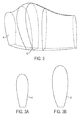
- a claw configuration 38 as shown in Figures 1-3 , means that the pod 12 has an aerodynamically shaped cross-section 40, 42 that gradually expands in width and height between the fore and aft ends 14, 16 such that the pod's cross-section 42 is widest and tallest halfway between these two ends 14, 16 .
- the fore and aft ends 14, 16 have substantially the same cross-section 40 and this cross-section expands in height and width relative to these ends 14, 16 the closer the cross-section is to the center of the pod 12.
- the width of the cross-section near the floor 20 of the pod 12 remains relatively consistent along the length of the pod, whereas the width in the upper half of the cross-section is primarily where the expansion occurs.
- the additional height of the claw configuration's cross-section in the middle of the pod 12 allows the center of gravity to start slightly higher than the optimized location, then as fuel is consumed the center of gravity is lowered and ultimately moves slightly below the optimized center of gravity when the fuel is nearly consumed. This results in an optimized overall change in the center of gravity throughout the course of the UAV's flight.
- the floor 20 at the fore end of the vertical fuel tank 10 is horizontal 36 for a short distance relative to the pod 12 and then transitions to an inclined floor 44 that extends to the sidewall 32 on the aft side of the vertical fuel tank 10.
- the horizontal portion of the floor 36 accommodates the outlet 18 and any fittings to connect the draw tube 24 to the outlet 18.
- the purpose of the inclined floor 44 is to ensure that fuel remains concentrated at the fore-side of the tank 10 even when the UAV pitches in the aft direction.
- a UAV typically pitches one degree in the direction of flight for every 2 knots that the UAV is traveling.
- the UAV is traveling backwards at 50 knots in the aft direction, then the UAV is pitched 25 degrees aft and the inclined floor 44 should be angled at 25 degrees to be horizontal relative to the ground.
- the floor 20 is inclined to accommodate at least the highest degree of pitch that the UAV may experience during backward flight to ensure that the fuel level does not pool on the aft side of the fuel tank 10.
- the UAV does not typically travel in the reverse direction for an extended period of time and the importance of the inclined floor 44 is only realized when fuel levels are substantially depleted during flight.
- the inclined floor 44 is angled at greater than zero degrees but less than or equal to 45 degrees. This configuration accommodates a UAV operating at up to 90 knots in the reverse direction.
- the sidewalls 22, 32 of the fuel tank 10 are substantially vertical relative to the floor of the pod 46. This embodiment contemplates that the fuel tank's side walls 22, 32 are substantially vertical relative to the horizontal floor 36.
- the outlet 18 is located at the center of the horizontal portion of the floor 36. Placing the outlet 18 midway between the port and starboard sides of the pod 12 accommodates the UAV's roll to one side or the other during flight.
- the vertical fuel tank 10 has a volume that is substantially one third of the volume of the pod 12.
- the volume of the fuel tank 10 relative to the volume of the overall pod 12 is important because the benefits realized by the claw configuration 38 related to the overall change in the center of gravity during flight are diminished as the volume of the fuel tank 10 is increased.
- the fore and aft sidewalls 14, 16 of the pod 12 and the vertical fuel tank 10 are coextensive such that the fuel tank 10 substantially fills the volume of the pod 12 except for the space between the inclined floor 44 and the floor of the pod 46. This embodiment maximizes the amount of fuel that can be used during flight.
- the fuel tank 10 contains anti-slosh foam.
- the anti-slosh foam is a fuel additive that aids in preventing the formation of air bubbles in the fuel tank 10 which could be drawn into the engine and result in vapor lock.
- the invention provides a vertical non-bladdered fuel tank system for a ducted fan vehicle comprising: (a) one or more pods 12 releasably attached to a core vehicle of a ducted fan, (b) a vertical fuel tank 10 contained by each of the one or more pods 12, wherein each vertical fuel tank 10 is centered between the fore and aft sides of each pod 14,16, (c) an outlet 18 in a floor 20 of each vertical fuel tank 10 located adjacent to a sidewall 22 on the fore side of each vertical fuel tank 10, wherein the outlet 18 is coupled to one or more draw tubes 24 contained by the core vehicle, and (d) a pressure release vent 26 located at the highlight 28 of the duct 30 of each pod 12.
- the one or more pods 12 have a claw configuration 38.
- each vertical fuel tank 10 is horizontal 36 for a short distance relative to the pod 12 at the fore end and then transitions to an inclined floor 44 which extends to the sidewall 32 on the aft side of the vertical fuel tank 10.
- the inclined floor 44 is angled at greater than zero degrees but less than or equal to 45 degrees.
- the sidewalls 22, 32 of the fuel tank 10 are substantially vertical relative to the floor of the pod 46.
- the outlet 18 is located at the center of the horizontal portion of the floor 36.
- the one or more pods 12 includes one pod 12 on the port side of the core vehicle and one pod 12 on the starboard side of the core vehicle.
- the port side is the left side of the UAV looking forward and the starboard side is the right side of the UAV looking forward.
- the fuel tank 10 in the pod 12 on the port side is connected to the fuel tank 10 in the pod 12 on the starboard side by a fuel line (not shown), wherein this fuel line is in a T-shape such that the port side and starboard side fuel tanks 10 share a joined fuel line to the engine.
- the fuel line constitutes the draw tube 24 and runs from the outlet 18 of the port side fuel tank 10 to the outlet 18 of the starboard fuel tank 10 in the core vehicle of the UAV.
- the fuel line branches off to connect with the engine creating a T-shape. Configuring the fuel line in this manner provides a vacuum that draws substantially equally from both fuel tanks 10.
- the invention provides a method for refueling a ducted fan vehicle utilizing a pod 12 containing a vertical non-bladdered fuel tank 10 comprising: (a) detaching a spent fuel pod 12 from a connector on a core vehicle, wherein the spent fuel pod 12 comprises (i) a vertical fuel tank 10 centered in between the fore and aft sides 14, 16 of the pod, (ii) an outlet 18 in a floor 20 of the vertical fuel tank 10 located adjacent to a sidewall 22 on the fore side of the vertical fuel tank 10, wherein the outlet 18 is coupled to a draw tube 24 contained by the core vehicle, and (iii) a pressure release vent 26 located at the highlight 28 of the pod's duct 30, and (b) attaching a prefilled fuel pod 12 to the core vehicle, wherein the prefilled fuel pod 12 has the same configuration as the spent fuel pod 12.
- detaching a spent fuel pod 12 requires releasing any latching mechanism between the spent fuel pod 12 and the core vehicle of the UAV and pulling the pod 12 until it separates from the core vehicle.
- attaching a prefilled fuel pod 12 to the core vehicle requires aligning the pod 12 over the core vehicle so that the contours of the pod and core vehicle mate, applying pressure to the pod 12 until the pod 12 snaps into place with any connectors on the core vehicle, and fastening any latching mechanism between the core vehicle and the prefilled fuel pod 12.
- a prefilled fuel pod 12 means that the pod 12 contains enough fuel for the UAV's next flight mission.
- Refueling the UAV according to this method allows the person who is refueling to complete the process in the dark and in a reduced timeframe compared to current methods available in the prior art.
- the spent fuel pod 12 has a claw configuration 38.
- the floor of the vertical fuel tank is horizontal 36 for a short distance relative to the pod 12 at the fore end and then transitions to an inclined floor 44 which extends to the sidewall 32 on the aft side of the vertical fuel tank 10.
Landscapes
- Engineering & Computer Science (AREA)
- Aviation & Aerospace Engineering (AREA)
- Mechanical Engineering (AREA)
- Chemical & Material Sciences (AREA)
- Combustion & Propulsion (AREA)
- Remote Sensing (AREA)
- Cooling, Air Intake And Gas Exhaust, And Fuel Tank Arrangements In Propulsion Units (AREA)
Applications Claiming Priority (1)
| Application Number | Priority Date | Filing Date | Title |
|---|---|---|---|
| US12/269,132 US8123169B2 (en) | 2008-11-12 | 2008-11-12 | Vertical non-bladdered fuel tank for a ducted fan vehicle |
Publications (1)
| Publication Number | Publication Date |
|---|---|
| EP2186726A2 true EP2186726A2 (en) | 2010-05-19 |
Family
ID=41528639
Family Applications (1)
| Application Number | Title | Priority Date | Filing Date |
|---|---|---|---|
| EP20090169295 Withdrawn EP2186726A2 (en) | 2008-11-12 | 2009-09-02 | Vertical non-bladdered fuel tank for a ducted fan vehicle |
Country Status (3)
| Country | Link |
|---|---|
| US (1) | US8123169B2 (enExample) |
| EP (1) | EP2186726A2 (enExample) |
| JP (1) | JP2010116140A (enExample) |
Cited By (1)
| Publication number | Priority date | Publication date | Assignee | Title |
|---|---|---|---|---|
| FR2994944A1 (fr) * | 2012-09-06 | 2014-03-07 | Eurocopter France | Dispositif de stockage muni d'un reservoir a paroi inclinable, aeronef et procede |
Families Citing this family (5)
| Publication number | Priority date | Publication date | Assignee | Title |
|---|---|---|---|---|
| JP2015009707A (ja) * | 2013-06-28 | 2015-01-19 | ヤマハ発動機株式会社 | 無人ヘリコプタ |
| US9221546B2 (en) | 2014-02-19 | 2015-12-29 | Aai Corporation | Aircraft hybrid fuel system |
| US10934012B2 (en) | 2018-06-08 | 2021-03-02 | Textron Systems Corporation | Using a passive separator to separate air and fuel of a fuel mixture passively when delivering fuel to a combustion engine of an unmanned aerial vehicle |
| CN112340037B (zh) * | 2020-11-06 | 2023-07-28 | 西北工业大学 | 适于无人机俯冲飞行的双腔体燃油系统及其设计方法 |
| US12145753B2 (en) * | 2022-08-09 | 2024-11-19 | Pete Bitar | Compact and lightweight drone delivery device called an ArcSpear electric jet drone system having an electric ducted air propulsion system and being relatively difficult to track in flight |
Family Cites Families (35)
| Publication number | Priority date | Publication date | Assignee | Title |
|---|---|---|---|---|
| US2609118A (en) * | 1949-01-29 | 1952-09-02 | Shell Dev | Aircraft fuel tank |
| US2719583A (en) * | 1951-01-02 | 1955-10-04 | Phillips Petroleum Co | Fuel tank for aircraft |
| DE3146262A1 (de) * | 1981-11-21 | 1983-05-26 | Erno-Raumfahrttechnik Gmbh, 2800 Bremen | "treibstofftank" |
| US4860972A (en) | 1988-02-09 | 1989-08-29 | Era Aviation, Inc. | Auxiliary fuel tanks for aircraft |
| US5888393A (en) * | 1989-07-18 | 1999-03-30 | The Boeing Company | Microparticle enhanced fibrous ceramic baffle for cryogenic liquid containers |
| US5152478A (en) | 1990-05-18 | 1992-10-06 | United Technologies Corporation | Unmanned flight vehicle including counter rotating rotors positioned within a toroidal shroud and operable to provide all required vehicle flight controls |
| FR2678895B1 (fr) * | 1991-07-08 | 1993-11-12 | Propulsion Ste Europeenne | Reservoir a tension superficielle, a debits de sortie multiples. |
| US5150857A (en) | 1991-08-13 | 1992-09-29 | United Technologies Corporation | Shroud geometry for unmanned aerial vehicles |
| US5295643A (en) * | 1992-12-28 | 1994-03-22 | Hughes Missile Systems Company | Unmanned vertical take-off and landing, horizontal cruise, air vehicle |
| US5983945A (en) | 1993-10-22 | 1999-11-16 | The United States Of America As Represented By The Secretary Of Transportation | Wing tank liner |
| US5371935A (en) * | 1993-12-20 | 1994-12-13 | United Technologies Corporation | Method for removing a fuel cell |
| US5575438A (en) | 1994-05-09 | 1996-11-19 | United Technologies Corporation | Unmanned VTOL ground surveillance vehicle |
| JP2775397B2 (ja) * | 1994-12-16 | 1998-07-16 | ケービー食品株式会社 | 液体バラスト装置 |
| US5695153A (en) | 1995-11-16 | 1997-12-09 | Northrop Grumman Corporation | Launcher system for an unmanned aerial vehicle |
| US6021978A (en) * | 1998-04-04 | 2000-02-08 | Goss; Clinton Gilbert | Anti-explosion protection system for flammable vapors |
| US6604706B1 (en) | 1998-08-27 | 2003-08-12 | Nicolae Bostan | Gyrostabilized self propelled aircraft |
| JP2003512215A (ja) | 1998-12-11 | 2003-04-02 | モラー・インターナショナル・インコーポレーテッド | ロボット制御または遠隔制御飛行プラットフォーム用の安定制御装置 |
| US6170778B1 (en) | 1999-04-22 | 2001-01-09 | Sikorsky Aircraft Corporation | Method of reducing a nose-up pitching moment on a ducted unmanned aerial vehicle |
| WO2001088648A2 (en) | 2000-05-17 | 2001-11-22 | Karem Abraham E | Intuitive vehicle and machine control |
| US6691949B2 (en) | 2001-07-06 | 2004-02-17 | The Charles Stark Draper Laboratory, Inc. | Vertical takeoff and landing aerial vehicle |
| US6721646B2 (en) | 2001-09-27 | 2004-04-13 | Ernest A. Carroll | Unmanned aircraft with automatic fuel-to-air mixture adjustment |
| US7032861B2 (en) | 2002-01-07 | 2006-04-25 | Sanders Jr John K | Quiet vertical takeoff and landing aircraft using ducted, magnetic induction air-impeller rotors |
| US20040094662A1 (en) | 2002-01-07 | 2004-05-20 | Sanders John K. | Vertical tale-off landing hovercraft |
| CN1662419A (zh) | 2002-06-28 | 2005-08-31 | Vtol技术有限公司 | 管道式气流动力设备 |
| ITTO20030588A1 (it) | 2003-07-30 | 2005-01-31 | Fiat Ricerche | Macchina volante. |
| US6889940B1 (en) * | 2004-01-29 | 2005-05-10 | The Boeing Company | Auxiliary fuel tank systems for aircraft and methods for their manufacture and use |
| DE202004017679U1 (de) | 2004-11-15 | 2006-03-23 | Dolmar Gmbh | Anlaufbremse für eine Heckenschere |
| US7658346B2 (en) * | 2005-02-25 | 2010-02-09 | Honeywell International Inc. | Double ducted hovering air-vehicle |
| US7520466B2 (en) | 2005-03-17 | 2009-04-21 | Nicolae Bostan | Gyro-stabilized air vehicle |
| US7748486B2 (en) | 2005-06-09 | 2010-07-06 | Honeywell International, Inc. | Landing gear for a hovercraft |
| US20070228214A1 (en) | 2005-09-26 | 2007-10-04 | Honeywell International Inc. | Autonomous launch pad for micro air vehicles |
| US7469725B2 (en) | 2006-02-22 | 2008-12-30 | Honeywell International Inc. | Method and apparatus for accurately delivering a predetermined amount of fuel to a vehicle |
| US7841563B2 (en) | 2006-03-27 | 2010-11-30 | Honeywell International Inc. | Ducted fan air data system |
| US20070244608A1 (en) | 2006-04-13 | 2007-10-18 | Honeywell International Inc. | Ground control station for UAV |
| US20070262195A1 (en) | 2006-05-11 | 2007-11-15 | Robert Bulaga | UAV With Control and Stability System |
-
2008
- 2008-11-12 US US12/269,132 patent/US8123169B2/en not_active Expired - Fee Related
-
2009
- 2009-09-02 EP EP20090169295 patent/EP2186726A2/en not_active Withdrawn
- 2009-09-07 JP JP2009205784A patent/JP2010116140A/ja not_active Ceased
Cited By (1)
| Publication number | Priority date | Publication date | Assignee | Title |
|---|---|---|---|---|
| FR2994944A1 (fr) * | 2012-09-06 | 2014-03-07 | Eurocopter France | Dispositif de stockage muni d'un reservoir a paroi inclinable, aeronef et procede |
Also Published As
| Publication number | Publication date |
|---|---|
| US20100116827A1 (en) | 2010-05-13 |
| US8123169B2 (en) | 2012-02-28 |
| JP2010116140A (ja) | 2010-05-27 |
Similar Documents
| Publication | Publication Date | Title |
|---|---|---|
| US8123169B2 (en) | Vertical non-bladdered fuel tank for a ducted fan vehicle | |
| US7621483B2 (en) | Aircraft and fuel venting system therefor | |
| US9676492B2 (en) | Dehumidifier | |
| US12017789B2 (en) | Onboard liquid hydrogen storage for a hydrogen aircraft | |
| EP3803097B1 (en) | Fuel delivery system using a passive separator to separate air and fuel of a fuel mixture passively when delivering fuel to a combustion engine of an unmanned aerial vehicle | |
| US8220747B2 (en) | System and method for a fuel bladder assembly with internal netting | |
| JP6703121B2 (ja) | 複数の燃料タンクを有する航空機の触媒不活性化システム | |
| US9809319B2 (en) | Aircraft fuel system | |
| CN102303705A (zh) | 满足带附加燃料箱的航空器的结构载荷要求的系统和方法 | |
| US20190055021A1 (en) | Modular Refueling Systems for Aircraft | |
| US9688415B2 (en) | Aircraft hybrid fuel system | |
| US20240359809A1 (en) | Fuel tank for an aircraft, fuselage of an aircraft, and aircraft | |
| CN109573071A (zh) | 一种无人机用异型分布式增压供油系统 | |
| EP3077290B1 (en) | Bubble collector for suction fuel system | |
| US20140130894A1 (en) | Nitrogen enriched air supply system and aircraft | |
| EP3006334B1 (en) | A system and a method for connecting an all-wing carrier with parasite flying units | |
| US20090145517A1 (en) | Protective devices for aircraft fuel filler ports | |
| US8622176B2 (en) | Gearbox oil reservoir shape optimization | |
| CN112498710A (zh) | 带增压燃油系统的无人机 | |
| CN209321256U (zh) | 一种无人机用异型分布式增压供油系统 | |
| JP3062914U (ja) | 高翼単葉機のガソリンタンク構造 | |
| CN214029170U (zh) | 带增压燃油系统的无人机 | |
| US9919807B2 (en) | External-bladder fuel system fluidly connectable to a fuel tank to receive excess | |
| CN224225299U (zh) | 一种用于无人飞行器大机动过载的集油装置 | |
| JP2003127996A (ja) | 燃料タンク防爆機能を備える燃料系統装置および燃料給油方法 |
Legal Events
| Date | Code | Title | Description |
|---|---|---|---|
| PUAI | Public reference made under article 153(3) epc to a published international application that has entered the european phase |
Free format text: ORIGINAL CODE: 0009012 |
|
| 17P | Request for examination filed |
Effective date: 20090902 |
|
| AK | Designated contracting states |
Kind code of ref document: A2 Designated state(s): AT BE BG CH CY CZ DE DK EE ES FI FR GB GR HR HU IE IS IT LI LT LU LV MC MK MT NL NO PL PT RO SE SI SK SM TR |
|
| STAA | Information on the status of an ep patent application or granted ep patent |
Free format text: STATUS: THE APPLICATION HAS BEEN WITHDRAWN |
|
| 18W | Application withdrawn |
Effective date: 20140124 |