US9676492B2 - Dehumidifier - Google Patents
Dehumidifier Download PDFInfo
- Publication number
- US9676492B2 US9676492B2 US14/529,372 US201414529372A US9676492B2 US 9676492 B2 US9676492 B2 US 9676492B2 US 201414529372 A US201414529372 A US 201414529372A US 9676492 B2 US9676492 B2 US 9676492B2
- Authority
- US
- United States
- Prior art keywords
- channel
- air
- pressure
- oxygen
- dehumidifier
- Prior art date
- Legal status (The legal status is an assumption and is not a legal conclusion. Google has not performed a legal analysis and makes no representation as to the accuracy of the status listed.)
- Active, expires
Links
Images


Classifications
-
- B—PERFORMING OPERATIONS; TRANSPORTING
- B64—AIRCRAFT; AVIATION; COSMONAUTICS
- B64D—EQUIPMENT FOR FITTING IN OR TO AIRCRAFT; FLIGHT SUITS; PARACHUTES; ARRANGEMENTS OR MOUNTING OF POWER PLANTS OR PROPULSION TRANSMISSIONS IN AIRCRAFT
- B64D37/00—Arrangements in connection with fuel supply for power plant
- B64D37/32—Safety measures not otherwise provided for, e.g. preventing explosive conditions
-
- F—MECHANICAL ENGINEERING; LIGHTING; HEATING; WEAPONS; BLASTING
- F24—HEATING; RANGES; VENTILATING
- F24F—AIR-CONDITIONING; AIR-HUMIDIFICATION; VENTILATION; USE OF AIR CURRENTS FOR SCREENING
- F24F3/00—Air-conditioning systems in which conditioned primary air is supplied from one or more central stations to distributing units in the rooms or spaces where it may receive secondary treatment; Apparatus specially designed for such systems
- F24F3/12—Air-conditioning systems in which conditioned primary air is supplied from one or more central stations to distributing units in the rooms or spaces where it may receive secondary treatment; Apparatus specially designed for such systems characterised by the treatment of the air otherwise than by heating and cooling
- F24F3/14—Air-conditioning systems in which conditioned primary air is supplied from one or more central stations to distributing units in the rooms or spaces where it may receive secondary treatment; Apparatus specially designed for such systems characterised by the treatment of the air otherwise than by heating and cooling by humidification; by dehumidification
-
- B—PERFORMING OPERATIONS; TRANSPORTING
- B01—PHYSICAL OR CHEMICAL PROCESSES OR APPARATUS IN GENERAL
- B01D—SEPARATION
- B01D53/00—Separation of gases or vapours; Recovering vapours of volatile solvents from gases; Chemical or biological purification of waste gases, e.g. engine exhaust gases, smoke, fumes, flue gases, aerosols
- B01D53/22—Separation of gases or vapours; Recovering vapours of volatile solvents from gases; Chemical or biological purification of waste gases, e.g. engine exhaust gases, smoke, fumes, flue gases, aerosols by diffusion
-
- B—PERFORMING OPERATIONS; TRANSPORTING
- B01—PHYSICAL OR CHEMICAL PROCESSES OR APPARATUS IN GENERAL
- B01D—SEPARATION
- B01D53/00—Separation of gases or vapours; Recovering vapours of volatile solvents from gases; Chemical or biological purification of waste gases, e.g. engine exhaust gases, smoke, fumes, flue gases, aerosols
- B01D53/26—Drying gases or vapours
- B01D53/268—Drying gases or vapours by diffusion
-
- B—PERFORMING OPERATIONS; TRANSPORTING
- B01—PHYSICAL OR CHEMICAL PROCESSES OR APPARATUS IN GENERAL
- B01D—SEPARATION
- B01D69/00—Semi-permeable membranes for separation processes or apparatus characterised by their form, structure or properties; Manufacturing processes specially adapted therefor
- B01D69/04—Tubular membranes
-
- B—PERFORMING OPERATIONS; TRANSPORTING
- B01—PHYSICAL OR CHEMICAL PROCESSES OR APPARATUS IN GENERAL
- B01D—SEPARATION
- B01D69/00—Semi-permeable membranes for separation processes or apparatus characterised by their form, structure or properties; Manufacturing processes specially adapted therefor
- B01D69/06—Flat membranes
-
- B—PERFORMING OPERATIONS; TRANSPORTING
- B01—PHYSICAL OR CHEMICAL PROCESSES OR APPARATUS IN GENERAL
- B01D—SEPARATION
- B01D71/00—Semi-permeable membranes for separation processes or apparatus characterised by the material; Manufacturing processes specially adapted therefor
- B01D71/02—Inorganic material
- B01D71/021—Carbon
-
- F—MECHANICAL ENGINEERING; LIGHTING; HEATING; WEAPONS; BLASTING
- F24—HEATING; RANGES; VENTILATING
- F24F—AIR-CONDITIONING; AIR-HUMIDIFICATION; VENTILATION; USE OF AIR CURRENTS FOR SCREENING
- F24F3/00—Air-conditioning systems in which conditioned primary air is supplied from one or more central stations to distributing units in the rooms or spaces where it may receive secondary treatment; Apparatus specially designed for such systems
- F24F3/12—Air-conditioning systems in which conditioned primary air is supplied from one or more central stations to distributing units in the rooms or spaces where it may receive secondary treatment; Apparatus specially designed for such systems characterised by the treatment of the air otherwise than by heating and cooling
- F24F3/14—Air-conditioning systems in which conditioned primary air is supplied from one or more central stations to distributing units in the rooms or spaces where it may receive secondary treatment; Apparatus specially designed for such systems characterised by the treatment of the air otherwise than by heating and cooling by humidification; by dehumidification
- F24F3/147—Air-conditioning systems in which conditioned primary air is supplied from one or more central stations to distributing units in the rooms or spaces where it may receive secondary treatment; Apparatus specially designed for such systems characterised by the treatment of the air otherwise than by heating and cooling by humidification; by dehumidification with both heat and humidity transfer between supplied and exhausted air
-
- H—ELECTRICITY
- H01—ELECTRIC ELEMENTS
- H01M—PROCESSES OR MEANS, e.g. BATTERIES, FOR THE DIRECT CONVERSION OF CHEMICAL ENERGY INTO ELECTRICAL ENERGY
- H01M8/00—Fuel cells; Manufacture thereof
- H01M8/04—Auxiliary arrangements, e.g. for control of pressure or for circulation of fluids
- H01M8/04082—Arrangements for control of reactant parameters, e.g. pressure or concentration
- H01M8/04089—Arrangements for control of reactant parameters, e.g. pressure or concentration of gaseous reactants
- H01M8/04119—Arrangements for control of reactant parameters, e.g. pressure or concentration of gaseous reactants with simultaneous supply or evacuation of electrolyte; Humidifying or dehumidifying
- H01M8/04156—Arrangements for control of reactant parameters, e.g. pressure or concentration of gaseous reactants with simultaneous supply or evacuation of electrolyte; Humidifying or dehumidifying with product water removal
- H01M8/04164—Arrangements for control of reactant parameters, e.g. pressure or concentration of gaseous reactants with simultaneous supply or evacuation of electrolyte; Humidifying or dehumidifying with product water removal by condensers, gas-liquid separators or filters
-
- B—PERFORMING OPERATIONS; TRANSPORTING
- B01—PHYSICAL OR CHEMICAL PROCESSES OR APPARATUS IN GENERAL
- B01D—SEPARATION
- B01D2259/00—Type of treatment
- B01D2259/45—Gas separation or purification devices adapted for specific applications
- B01D2259/4566—Gas separation or purification devices adapted for specific applications for use in transportation means
- B01D2259/4575—Gas separation or purification devices adapted for specific applications for use in transportation means in aeroplanes or space ships
-
- B—PERFORMING OPERATIONS; TRANSPORTING
- B64—AIRCRAFT; AVIATION; COSMONAUTICS
- B64D—EQUIPMENT FOR FITTING IN OR TO AIRCRAFT; FLIGHT SUITS; PARACHUTES; ARRANGEMENTS OR MOUNTING OF POWER PLANTS OR PROPULSION TRANSMISSIONS IN AIRCRAFT
- B64D41/00—Power installations for auxiliary purposes
- B64D2041/005—Fuel cells
-
- F—MECHANICAL ENGINEERING; LIGHTING; HEATING; WEAPONS; BLASTING
- F24—HEATING; RANGES; VENTILATING
- F24F—AIR-CONDITIONING; AIR-HUMIDIFICATION; VENTILATION; USE OF AIR CURRENTS FOR SCREENING
- F24F3/00—Air-conditioning systems in which conditioned primary air is supplied from one or more central stations to distributing units in the rooms or spaces where it may receive secondary treatment; Apparatus specially designed for such systems
- F24F3/12—Air-conditioning systems in which conditioned primary air is supplied from one or more central stations to distributing units in the rooms or spaces where it may receive secondary treatment; Apparatus specially designed for such systems characterised by the treatment of the air otherwise than by heating and cooling
- F24F3/14—Air-conditioning systems in which conditioned primary air is supplied from one or more central stations to distributing units in the rooms or spaces where it may receive secondary treatment; Apparatus specially designed for such systems characterised by the treatment of the air otherwise than by heating and cooling by humidification; by dehumidification
- F24F2003/1435—Air-conditioning systems in which conditioned primary air is supplied from one or more central stations to distributing units in the rooms or spaces where it may receive secondary treatment; Apparatus specially designed for such systems characterised by the treatment of the air otherwise than by heating and cooling by humidification; by dehumidification comprising semi-permeable membrane
-
- F—MECHANICAL ENGINEERING; LIGHTING; HEATING; WEAPONS; BLASTING
- F24—HEATING; RANGES; VENTILATING
- F24F—AIR-CONDITIONING; AIR-HUMIDIFICATION; VENTILATION; USE OF AIR CURRENTS FOR SCREENING
- F24F3/00—Air-conditioning systems in which conditioned primary air is supplied from one or more central stations to distributing units in the rooms or spaces where it may receive secondary treatment; Apparatus specially designed for such systems
- F24F3/12—Air-conditioning systems in which conditioned primary air is supplied from one or more central stations to distributing units in the rooms or spaces where it may receive secondary treatment; Apparatus specially designed for such systems characterised by the treatment of the air otherwise than by heating and cooling
- F24F3/14—Air-conditioning systems in which conditioned primary air is supplied from one or more central stations to distributing units in the rooms or spaces where it may receive secondary treatment; Apparatus specially designed for such systems characterised by the treatment of the air otherwise than by heating and cooling by humidification; by dehumidification
- F24F2003/144—Air-conditioning systems in which conditioned primary air is supplied from one or more central stations to distributing units in the rooms or spaces where it may receive secondary treatment; Apparatus specially designed for such systems characterised by the treatment of the air otherwise than by heating and cooling by humidification; by dehumidification by dehumidification only
-
- H—ELECTRICITY
- H01—ELECTRIC ELEMENTS
- H01M—PROCESSES OR MEANS, e.g. BATTERIES, FOR THE DIRECT CONVERSION OF CHEMICAL ENERGY INTO ELECTRICAL ENERGY
- H01M2250/00—Fuel cells for particular applications; Specific features of fuel cell system
- H01M2250/20—Fuel cells in motive systems, e.g. vehicle, ship, plane
-
- Y—GENERAL TAGGING OF NEW TECHNOLOGICAL DEVELOPMENTS; GENERAL TAGGING OF CROSS-SECTIONAL TECHNOLOGIES SPANNING OVER SEVERAL SECTIONS OF THE IPC; TECHNICAL SUBJECTS COVERED BY FORMER USPC CROSS-REFERENCE ART COLLECTIONS [XRACs] AND DIGESTS
- Y02—TECHNOLOGIES OR APPLICATIONS FOR MITIGATION OR ADAPTATION AGAINST CLIMATE CHANGE
- Y02E—REDUCTION OF GREENHOUSE GAS [GHG] EMISSIONS, RELATED TO ENERGY GENERATION, TRANSMISSION OR DISTRIBUTION
- Y02E60/00—Enabling technologies; Technologies with a potential or indirect contribution to GHG emissions mitigation
- Y02E60/30—Hydrogen technology
- Y02E60/50—Fuel cells
-
- Y02T90/32—
-
- Y02T90/36—
-
- Y—GENERAL TAGGING OF NEW TECHNOLOGICAL DEVELOPMENTS; GENERAL TAGGING OF CROSS-SECTIONAL TECHNOLOGIES SPANNING OVER SEVERAL SECTIONS OF THE IPC; TECHNICAL SUBJECTS COVERED BY FORMER USPC CROSS-REFERENCE ART COLLECTIONS [XRACs] AND DIGESTS
- Y02—TECHNOLOGIES OR APPLICATIONS FOR MITIGATION OR ADAPTATION AGAINST CLIMATE CHANGE
- Y02T—CLIMATE CHANGE MITIGATION TECHNOLOGIES RELATED TO TRANSPORTATION
- Y02T90/00—Enabling technologies or technologies with a potential or indirect contribution to GHG emissions mitigation
- Y02T90/40—Application of hydrogen technology to transportation, e.g. using fuel cells
Definitions
- the invention relates to a dehumidifier, and a method of dehumidifying air.
- a first aspect of the invention provides a dehumidifier comprising: a first channel for transporting air at a first pressure; a second channel for transporting air at a second pressure lower than the first pressure; and a graphene oxide barrier separating the first channel and the second channel; wherein the relatively lower pressure of air in the second channel causes water vapour to be drawn out of the air in the first channel.
- the first channel and the second channel may be elongate.
- the second channel may be formed concentrically around the first channel.
- the first channel and the second channel may be helical or planar.
- the graphene oxide barrier may be a graphene oxide membrane.
- a second aspect of the invention provides a system for supplying inert gas to a fuel tank, the system comprising: a dehumidifier as described above; a fuel cell configured to generate oxygen-depleted air to be fed into the first channel of the dehumidifier, for dehumidifying; and a fuel tank for receiving and containing the dehumidified oxygen-depleted air.
- the fuel cell may be a hydrogen fuel cell.
- the system may include a vent between the dehumidifier and the fuel tank, the vent configured to vent the dehumidified oxygen-depleted air when the flow of dehumidified oxygen-depleted air into the fuel tank reaches a predefined level.
- the system may include an air inlet for allowing the ingress of vent air into the second channel of the dehumidifier.
- the vent air may be relatively colder than the oxygen-depleted air.
- the vent air may be at a relatively lower pressure than the oxygen-depleted air.
- the system may include a water outlet formed at a first end of the dehumidifier, wherein the dehumidifier is inclined such that the water outlet is lower than a second end of the dehumidifier.
- the system may include a water tank for receiving and containing the water drawn out of, or condensed from, the air in the second channel.
- a third aspect of the invention provides a vehicle comprising the system described above.
- the vehicle may be an aircraft.
- the aircraft may have an air inlet configured to allow the ingress of air from outside the aircraft.
- a fourth aspect of the invention provides a method of dehumidifying air, the method comprising: providing a dehumidifier having a first channel, a second channel and a graphene oxide barrier separating the first channel and the second channel; generating a flow of air at a first pressure in the first channel; and generating a flow of air at a second pressure in the second channel, the second pressure being lower than the first channel such that water is drawn out from the air in the first channel, through the graphene oxide barrier and into the second channel.
- the air flowing into the first channel may be oxygen-depleted air.
- the method may include: receiving, in a water tank, the water drawn out, or condensed, from the oxygen-depleted air.
- the temperature and/or pressure of air flowing in the second channel may be lower relative to the temperature and/or pressure of air flowing in the first channel.
- a fifth aspect of the invention provides a method of supplying inert gas to a fuel tank, the method comprising: generating, in a fuel cell, oxygen-depleted air; dehumidifying the oxygen-depleted air as described above; and receiving, in a fuel tank, the dehumidified oxygen-depleted air.
- FIG. 1 is a schematic view of an inerting system
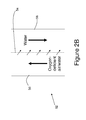
- FIGS. 2A and 2B are schematic partial views of a dehumidifier for removing water vapour from a fluid
- FIG. 3 is a side view of part of an aircraft incorporating the dehumidifier of FIGS. 2A and 2B .
- FIG. 1 shows a system for supplying inert gas to a fuel tank, or inerting system 10 .
- the inerting system 10 is described in the context of a system for inerting air in a fuel tank of an aircraft.
- the inerting system 10 could alternatively be incorporated into, for example, a building or a land or sea vehicle.
- the inerting system 10 includes a fuel cell 12 , a dehumidifier apparatus 14 and a fuel tank 16 for containing fuel 18 .
- the fuel cell 12 is in fluid communication with the fuel tank 16 via the dehumidifier apparatus 14 .
- the fuel cell 12 is configured to receive hydrogen via a hydrogen input 20 and air via an air input 22 .
- the hydrogen supplied to the fuel cell 12 may be stored under pressure in a hydrogen canister (not shown).
- the air supplied to the fuel cell 12 may be engine bleed air, directed to the fuel cell from an engine of the aircraft, compressed air stored under pressure in an air canister (not shown), or air pumped into the fuel cell from some other source, for example from outside the aircraft or from within the cabin of the aircraft.
- hydrogen is catalytically reacted with oxygen in the air to produce electricity which can be provided to the aircraft via a connection 24 to be used by the aircraft while on the ground, for example for ground propulsion, or while airborne, for example for emergency power or lighting.
- a by-product of the generation of electricity by the fuel cell 12 is oxygen-depleted air (ODA), which typically has an oxygen concentration of less than around 10.5%.
- ODA oxygen-depleted air
- the oxygen-depleted air is directed via the dehumidifier apparatus 14 into the fuel tank 16 in order to reduce the amount of oxygen in the fuel tank, thereby reducing the flammability of the fuel 18 in the fuel tank.
- the oxygen-depleted air generated by the fuel cell 12 typically has a temperature of around 80 degrees and typically has a humidity of around 100% due to the catalytic process via which it is produced. Therefore, prior to feeding the oxygen-depleted air into the fuel tank, it is advantageous to reduce the temperature and/or the humidity of the oxygen-depleted air.
- the dehumidifier apparatus 14 includes a double-walled tube 28 having a generally cylindrical shape and including an outer tube 30 and an inner tube 32 .
- the inner tube 32 forms a first channel for transporting air, such as oxygen-depleted air, and the outer tube 30 and the inner tube 32 define a second channel for transporting air.
- the outer tube 30 is formed of metal.
- the outer tube 30 may be formed of plastics material or any other material suitable for transporting fluids such as water and air.
- the inner tube 32 is connected to the outer tube 30 using known means, for example spokes or connectors (not shown) extending between the inner tube and the outer tube.
- the inner tube 32 is formed of graphene oxide.
- Graphene oxide is an oxidised form of graphene, which typically takes the form of a sheet formed of a single atomic layer of carbon, where each carbon atom is bonded to two oxygen atoms. Graphene oxide is permeable to water and water vapour, but is impermeable to almost all other fluids, including air. In some embodiments, the graphene oxide inner tube is supported on a porous structural former (not shown).
- An inlet 34 is provided at first end 36 of the tube 28 through which oxygen-depleted air is able to enter the dehumidifier apparatus 14 from the fuel cell 12 .
- a second end 38 of the tube 28 is connected to the fuel tank 16 .
- a vent air inlet 40 is formed at the second end 38 of the tube 28 , and allows air from outside the aircraft to flow into the second channel of the tube in a direction opposite to the direction of flow of air in the first channel.
- the air from outside the aircraft can be directed into the vent air inlet 40 as the aircraft moves forward.
- air may be obtained via some other source, such as a fan located within the aircraft, and pumped from the second channel of the tube.
- a water outlet 42 is provided at the first end 36 of the tube 28 , and connects the tube to a water tank 44 which is configured to collect water drawn from the oxygen-depleted air, as will be discussed below.
- the water drawn from the oxygen-depleted air is fed into the aircraft for use in various aircraft systems.
- a vent air outlet 46 allows ambient air to exit the water tank 44 , after the ambient air has passed through the tube 28 .
- the tube 28 is inclined relative to horizontal so that the tube slopes towards the first end 36 . This allows water drawn out from the oxygen-depleted air in the first channel to flow towards the water outlet 42 and into the water tank 44 .
- a regulator valve 48 is located between the dehumidifier apparatus 14 and the fuel tank 16 , and is configured to restrict the amount of oxygen-depleted air that is able to enter the fuel tank. In some embodiments, the regulator valve 48 restricts the amount of oxygen-depleted air entering the fuel tank when the flow of oxygen-depleted air into the fuel tank exceeds a predefined level. Typically, when the flow of oxygen-depleted air into the fuel tank 16 is such that the air in the fuel tank has an oxygen content of less than about 12%, then the regulator valve 48 restricts the flow of oxygen-depleted air into the fuel tank.
- the flow rate of ODA into the fuel tank 16 is restricted to around, or slightly greater than, the rate at which the fuel 18 is burnt by the aircraft to avoid excess fuel vapour being vented to the air outside the aircraft. Any excess oxygen-depleted air that passes through the dehumidifier apparatus 14 and is restricted from entering the fuel tank 16 is ejected from the system 10 via an exhaust 50 .
- An atmospheric vent 52 provides a fluid communication link between the fuel tank 16 and the air surrounding the aircraft, thereby allowing the pressure in the fuel tank to be equalised with the air outside the aircraft.
- air from outside the aircraft flows in the second channel in the opposite direction to the oxygen-depleted air flowing in the first channel.
- the vent air inlet 40 is located at the first end 36 of the dehumidifier 14
- the vent air outlet 42 is located at the second end 38 of the dehumidifier.
- the flow air from outside the aircraft along the second channel is in the same direction as the direction of the flow of oxygen-depleted air in the first channel.
- oxygen-depleted air that is output from the fuel cell 12 enters the first channel formed by the graphene oxide inner tube 32 of the dehumidifier apparatus 14 .
- Air from outside the aircraft flows into the vent air inlet 40 .
- the air is able to flow along the length of the tube 28 in the second channel, formed between the outer tube 30 and the inner tube 32 , but is not able to pass through the impermeable wall of the inner tube since graphene oxide is impermeable to air.
- the pressure of air surrounding aircraft in flight at cruise altitude is typically around 2.7 p.s.i., which is significantly lower than that of the oxygen-depleted air, which exits the fuel cell 12 at a pressure of around 16 p.s.i.
- the pressure of fluid in the region between the graphene oxide inner tube 32 and the outer tube 30 is significantly lower than that of the fluid within the inner tube.
- the relatively lower pressure causes water vapour in the oxygen-depleted air to be drawn out of the inner tube 32 , through the graphene oxide, and into the second channel formed in the region between the inner tube and the outer tube 30 , as depicted by arrows A.
- Most other liquids and gases within the inner tube 32 including all of the constituents of oxygen-depleted air, are unable to pass through the graphene oxide, so remain in the first channel formed by the inner tube.
- the ambient air surrounding the aircraft is typically at a temperature of around minus 50 degrees centigrade, which is significantly cooler than the oxygen-depleted air which typically has a temperature of around 80 degrees centigrade as it exits the fuel cell 12 .
- the relatively cooler ambient air flowing in the second channel between the inner tube 32 and the outer tube 30 causes a decrease in the temperature of the oxygen-depleted air flowing within the inner tube such that, when the oxygen-depleted air reaches the fuel tank 16 , its temperature has decreased sufficiently to significantly reduce the flammability of the fuel 18 .
- the temperature of the oxygen-depleted air in the fuel tank is between around 5 degrees centigrade and 40 degrees centigrade.
- the oxygen-depleted air that reaches the fuel tank 16 is significantly less humid than the air entering the dehumidifier apparatus 14 .
- the dehumidifier apparatus 14 is inclined relative to horizontal, such that water drawn out of the oxygen-depleted air flows along the tube 28 towards the water tank 44 . More specifically, the dehumidifier apparatus 14 is arranged such that the water outlet 42 at the first end 36 of the tube 28 is lower than the second end 38 of the tube, such that gravity causes water in the second channel to flow towards the water outlet 42 and to drip into the water tank 44 . The air from outside the aircraft flowing the second channel flows through the water tank 44 and exits the system 10 via the vent air outlet 46 .
- a fan or pump may be provided to aid the flow of ambient air and water along the tube 28 of the dehumidifier apparatus 14 .
- a fan or pump also serves to reduce the pressure of air flowing in the second channel in the region between the inner tube 32 and the outer tube 30 , thereby aiding the removal of water from the oxygen-depleted air flowing through the inner tube 32 .
- the dehumidifier apparatus 14 has been described as a tubular arrangement having a generally cylindrical shape. However, in some embodiments, the dehumidifier apparatus 14 may not have a double-tube form.
- the dehumidifier apparatus 14 includes a tube 52 having a generally square or rectangular cross section. The tube 52 is divided along its longitudinal axis by a horizontal or vertical graphene oxide wall 54 , which forms a first channel 56 , along which oxygen-depleted air is able to flow in a first direction, and a second channel 58 , along which ambient air is able to flow in a second direction opposite to the first direction.
- the oxygen-depleted air flows in the upper, or top channel.
- the oxygen-depleted air in the first channel flows in the same direction as the air in the second direction.
- the ambient air flows along the second channel 58 of the tube 52 , it reduces the temperature of the oxygen-depleted air flowing along the first channel 56 . Furthermore, the ambient air is at a pressure significantly lower than that of the oxygen-depleted air and, as a consequence, water in the oxygen-depleted air is drawn out through the graphene oxide wall 54 . The drawn-out water is then urged by the flow of ambient air along the second channel 56 towards the water tank 44 . The cooled and less humid oxygen-depleted air flows along the first channel to the fuel tank 16 .
- FIG. 3 shows a side view of part of an aircraft 60 having a fuselage 62 , wings 64 and engines 66 . Only one wing 64 and engine 66 is shown.
- the wing 64 has a wing box which is bounded by front and rear spars; inboard and outboard ribs; and upper and lower covers, none of which is shown, but which together form the walls of the fuel tank 16 .
- FIG. 3 illustrates schematically how the inerting system 10 might be incorporated into the aircraft 60 .
- the inerting system 10 is not drawn to scale, and the various components of the inerting system may be located differently to how they are shown.
- a hydrogen tank 68 supplies hydrogen to the fuel cell 12 .
- a heater (not shown) is connected to the vent air inlet 40 to raise the temperature of the ambient air entering the dehumidifier apparatus 14 , to ensure that the water drawn out through the graphene oxide inner tube does not freeze within the tube 28 .
- the tube 28 of the dehumidifier apparatus 14 has been described as a single straight tube. However, in other embodiments, multiple tubes may be used to transport the oxygen-depleted air from the fuel cell 12 to the fuel tank 16 .
- a straight tube 28 as described above may have sufficient length between the fuel cell 12 and the fuel tank 16 for a sufficient decrease in humidity and temperature of the oxygen-depleted air.
- the straight tube 28 may be replaced by a longer tube which is helical or coiled. In such an embodiment, the distance that the oxygen-depleted air has must travel between the fuel cell 12 and the fuel tank 16 is greater and, therefore, the oxygen-depleted air has longer to reduce in temperature and humidity.
- the tube 28 forming the first and second channels may be planar.
- the tube 28 be comprise a single coiled tube located within the water tank 44 . Cooling air can be passed through the water tank 44 so that the water vapour drawn out from the tube 28 is delivered directly into the water tank.
Abstract
Description
Claims (16)
Applications Claiming Priority (2)
| Application Number | Priority Date | Filing Date | Title |
|---|---|---|---|
| GB1319338.8A GB2519959A (en) | 2013-11-01 | 2013-11-01 | Dehumidifier |
| GB1319338.8 | 2013-11-01 |
Publications (2)
| Publication Number | Publication Date |
|---|---|
| US20150122814A1 US20150122814A1 (en) | 2015-05-07 |
| US9676492B2 true US9676492B2 (en) | 2017-06-13 |
Family
ID=49767533
Family Applications (1)
| Application Number | Title | Priority Date | Filing Date |
|---|---|---|---|
| US14/529,372 Active 2035-07-29 US9676492B2 (en) | 2013-11-01 | 2014-10-31 | Dehumidifier |
Country Status (2)
| Country | Link |
|---|---|
| US (1) | US9676492B2 (en) |
| GB (1) | GB2519959A (en) |
Cited By (3)
| Publication number | Priority date | Publication date | Assignee | Title |
|---|---|---|---|---|
| US20150040986A1 (en) * | 2012-03-21 | 2015-02-12 | Airbus Operations Limited | Conditioning system for fuel cell exhaust |
| US20160296884A1 (en) * | 2013-11-19 | 2016-10-13 | Siemens Aktiengesellschaft | Device For The Separation Of Water From A Fluid Flow Containing Water |
| US11493242B2 (en) | 2018-11-27 | 2022-11-08 | Aktiebolaget Skf | Cooling system for a refrigerant lubricated bearing assembly |
Families Citing this family (11)
| Publication number | Priority date | Publication date | Assignee | Title |
|---|---|---|---|---|
| US9358508B2 (en) * | 2013-04-25 | 2016-06-07 | Lockheed Martin Corporation | Dryer and water recovery/purification unit employing graphene oxide or perforated graphene monolayer membranes |
| KR20160098389A (en) * | 2013-12-18 | 2016-08-18 | 칼튼 라이프 서포트 시스템즈, 아이엔씨. | Air drying system for obogs |
| US9932234B2 (en) * | 2015-07-13 | 2018-04-03 | Hamilton Sundstrand Corporation | Membrane-based air separation module |
| US9795930B2 (en) | 2015-10-22 | 2017-10-24 | Industrial Technology Research Institute | Water separation composite membrane |
| US9981212B2 (en) * | 2015-11-30 | 2018-05-29 | Korea Institute Of Energy Research | Method for manufacturing porous graphene filter, porous graphene filter manufactured using same, and filter apparatus using porous graphene filter |
| US9963792B2 (en) * | 2015-12-15 | 2018-05-08 | Hamilton Sundstrand Corporation | Electrochemical gas separator for combustion prevention and suppression |
| GB2549721A (en) * | 2016-04-25 | 2017-11-01 | Airbus Operations Ltd | A fuel flow system |
| AT518169B1 (en) * | 2016-05-04 | 2017-08-15 | Ecool Advanced Urban Eng Gmbh | WATER RECOVERY DEVICE |
| FR3063438A1 (en) * | 2017-03-03 | 2018-09-07 | L'air Liquide, Societe Anonyme Pour L'etude Et L'exploitation Des Procedes Georges Claude | DRYING A FLOW OF AIR USING A GRAPHENE OXIDE MEMBRANE |
| US10532311B2 (en) * | 2017-06-30 | 2020-01-14 | Hamilton Sundstrand Corporation | Inert gas generation with dehumidification |
| FR3080365B1 (en) * | 2018-04-24 | 2020-11-27 | Airbus Operations Sas | PROCESS FOR THE TREATMENT OF AN AIRCRAFT TANK TO LIMIT THE PROLIFERATION OF MICRO-ORGANISMS AND DEVICE FOR ITS IMPLEMENTATION |
Citations (29)
| Publication number | Priority date | Publication date | Assignee | Title |
|---|---|---|---|---|
| US4903503A (en) * | 1987-05-12 | 1990-02-27 | Camp Dresser & Mckee | Air conditioning apparatus |
| US5131238A (en) * | 1985-04-03 | 1992-07-21 | Gershon Meckler | Air conditioning apparatus |
| US5181387A (en) * | 1985-04-03 | 1993-01-26 | Gershon Meckler | Air conditioning apparatus |
| US5235843A (en) * | 1988-08-24 | 1993-08-17 | The Dow Chemical Company | Method and apparatus for analyzing volatile chemical components in a liquid |
| DE4323719C2 (en) | 1993-07-15 | 1995-06-22 | Daimler Benz Aerospace Airbus | Method and device for carrying out the method for water supply on board an aircraft |
| DE4302319C2 (en) | 1992-05-21 | 1996-03-28 | Daimler Benz Aerospace Airbus | Process and arrangement for treating waste water in aircraft |
| US6087029A (en) * | 1998-01-06 | 2000-07-11 | Aer Energy Resources, Inc. | Water recovery using a bi-directional air exchanger for a metal-air battery |
| US6293121B1 (en) * | 1988-10-13 | 2001-09-25 | Gaudencio A. Labrador | Water-mist blower cooling system and its new applications |
| DE10249588A1 (en) | 2002-04-16 | 2004-05-13 | Airbus Deutschland Gmbh | Water-generating method for generating water on board aircraft via fuel cells integrates a water-generating unit in an aircraft's driving gear as high-temperature fuel cells |
| US20070111060A1 (en) | 2005-11-17 | 2007-05-17 | Airbus Deutschland Gmbh | Safety System For Reducing The Explosion Risk Of A Fuel Tank |
| DE102006034816A1 (en) | 2006-07-27 | 2008-01-31 | Airbus Deutschland Gmbh | Cooling system for cooling fuel cell system on board aircraft, comprises hydrogen reservoir for cooling fuel cell system when unloading hydrogen reservoir and system also has connection device for connection to external cooling system |
| US20080057368A1 (en) * | 2006-08-29 | 2008-03-06 | Mcelroy Richard L | Motion fuel cell |
| WO2008089484A1 (en) * | 2007-01-20 | 2008-07-24 | Dais Analytic Corporation | Multi-phase selective mass transfer through a membrane |
| US20080223212A1 (en) * | 2007-03-16 | 2008-09-18 | Crowder Robert O | Reducing moisture content of compressed air |
| DE102007046381A1 (en) | 2007-09-27 | 2009-04-09 | Airbus Deutschland Gmbh | Fuel cell system with suction for an aircraft |
| WO2009158030A1 (en) | 2008-06-25 | 2009-12-30 | Gore Enterprise Holdings, Inc. | Composite membrane and moisture adjustment module using the same |
| US20100047634A1 (en) * | 2008-01-09 | 2010-02-25 | Ultracell Corporation | Portable reformed fuel cell systems with water recovery |
| US20100212503A1 (en) | 2007-08-02 | 2010-08-26 | National Institute Of Advanced Industrial Science And Technology | Hollow fiber carbon membrane and method for production thereof |
| US20110062082A1 (en) * | 2009-09-16 | 2011-03-17 | Gm Global Technology Operations, Inc. | Membrane separation of water and fuel from engine oil in an internal combustion engine |
| WO2011036027A1 (en) | 2009-09-03 | 2011-03-31 | Airbus Operations Gmbh | Concept for drying exhaust gas of a fuel cell system utilizing the liquid hydrogen as a heat sink |
| US20120118147A1 (en) * | 2010-11-12 | 2012-05-17 | The Texas A&M University System | Systems and methods for air dehumidification and cooling with membrane water vapor rejection |
| US8256524B2 (en) | 2005-11-10 | 2012-09-04 | Airbus Operations Gmbh | Fire protection with fuel cell exhaust air |
| US20120304862A1 (en) * | 2011-06-03 | 2012-12-06 | Taylor Gareth P | Flat panel contactors and methods |
| US20130056177A1 (en) * | 2011-09-02 | 2013-03-07 | Venmar Ces, Inc. | Energy exchange system for conditioning air in an enclosed structure |
| US20140150287A1 (en) * | 2011-07-14 | 2014-06-05 | Dow Corning Corporation | Method of drying material by membrane dehumidified air |
| US20140157985A1 (en) * | 2011-05-03 | 2014-06-12 | University Of Mississippi | Dehumidification Systems and Methods Thereof |
| US20150231577A1 (en) * | 2012-08-15 | 2015-08-20 | The University Of Manchester | Separation of Water Using a Membrane |
| US20160074814A1 (en) * | 2013-04-24 | 2016-03-17 | Iucf-Hyu (Industry-University Cooperation Foundation Hanyang University) | Composite separation membrane including graphene oxide coating layer and method for manufacturing the same |
| US20160158694A1 (en) * | 2010-09-07 | 2016-06-09 | Dais Analytic Corporation | Fluid treatment systems and methods using selective transfer membranes |
-
2013
- 2013-11-01 GB GB1319338.8A patent/GB2519959A/en not_active Withdrawn
-
2014
- 2014-10-31 US US14/529,372 patent/US9676492B2/en active Active
Patent Citations (34)
| Publication number | Priority date | Publication date | Assignee | Title |
|---|---|---|---|---|
| US5131238A (en) * | 1985-04-03 | 1992-07-21 | Gershon Meckler | Air conditioning apparatus |
| US5181387A (en) * | 1985-04-03 | 1993-01-26 | Gershon Meckler | Air conditioning apparatus |
| US4903503A (en) * | 1987-05-12 | 1990-02-27 | Camp Dresser & Mckee | Air conditioning apparatus |
| US5235843A (en) * | 1988-08-24 | 1993-08-17 | The Dow Chemical Company | Method and apparatus for analyzing volatile chemical components in a liquid |
| US6293121B1 (en) * | 1988-10-13 | 2001-09-25 | Gaudencio A. Labrador | Water-mist blower cooling system and its new applications |
| DE4302319C2 (en) | 1992-05-21 | 1996-03-28 | Daimler Benz Aerospace Airbus | Process and arrangement for treating waste water in aircraft |
| DE4323719C2 (en) | 1993-07-15 | 1995-06-22 | Daimler Benz Aerospace Airbus | Method and device for carrying out the method for water supply on board an aircraft |
| US6087029A (en) * | 1998-01-06 | 2000-07-11 | Aer Energy Resources, Inc. | Water recovery using a bi-directional air exchanger for a metal-air battery |
| DE10249588A1 (en) | 2002-04-16 | 2004-05-13 | Airbus Deutschland Gmbh | Water-generating method for generating water on board aircraft via fuel cells integrates a water-generating unit in an aircraft's driving gear as high-temperature fuel cells |
| US8256524B2 (en) | 2005-11-10 | 2012-09-04 | Airbus Operations Gmbh | Fire protection with fuel cell exhaust air |
| DE102005054885A1 (en) | 2005-11-17 | 2007-05-31 | Airbus Deutschland Gmbh | Safety system for reducing explosion risk of fuel tank, includes protective gas generating device comprising fuel cell system having fuel cell and providing protective gas generated by fuel cell to delivery device for delivery to fuel tank |
| US20070111060A1 (en) | 2005-11-17 | 2007-05-17 | Airbus Deutschland Gmbh | Safety System For Reducing The Explosion Risk Of A Fuel Tank |
| US7759011B2 (en) | 2005-11-17 | 2010-07-20 | Airbus Deutschland Gmbh | Safety system for reducing the explosion risk of a fuel tank |
| DE102006034816A1 (en) | 2006-07-27 | 2008-01-31 | Airbus Deutschland Gmbh | Cooling system for cooling fuel cell system on board aircraft, comprises hydrogen reservoir for cooling fuel cell system when unloading hydrogen reservoir and system also has connection device for connection to external cooling system |
| US8372554B2 (en) | 2006-07-27 | 2013-02-12 | Airbus Deutschland | Hydride fuel-cell cooler and condensate cooler for aircraft |
| US20080057368A1 (en) * | 2006-08-29 | 2008-03-06 | Mcelroy Richard L | Motion fuel cell |
| WO2008089484A1 (en) * | 2007-01-20 | 2008-07-24 | Dais Analytic Corporation | Multi-phase selective mass transfer through a membrane |
| US8500960B2 (en) * | 2007-01-20 | 2013-08-06 | Dais Analytic Corporation | Multi-phase selective mass transfer through a membrane |
| US20080223212A1 (en) * | 2007-03-16 | 2008-09-18 | Crowder Robert O | Reducing moisture content of compressed air |
| US20100212503A1 (en) | 2007-08-02 | 2010-08-26 | National Institute Of Advanced Industrial Science And Technology | Hollow fiber carbon membrane and method for production thereof |
| DE102007046381A1 (en) | 2007-09-27 | 2009-04-09 | Airbus Deutschland Gmbh | Fuel cell system with suction for an aircraft |
| US8623559B2 (en) | 2007-09-27 | 2014-01-07 | Airbus Operations Gmbh | Fuel cell system with suction operation for an aircraft |
| US20100047634A1 (en) * | 2008-01-09 | 2010-02-25 | Ultracell Corporation | Portable reformed fuel cell systems with water recovery |
| WO2009158030A1 (en) | 2008-06-25 | 2009-12-30 | Gore Enterprise Holdings, Inc. | Composite membrane and moisture adjustment module using the same |
| WO2011036027A1 (en) | 2009-09-03 | 2011-03-31 | Airbus Operations Gmbh | Concept for drying exhaust gas of a fuel cell system utilizing the liquid hydrogen as a heat sink |
| US20110062082A1 (en) * | 2009-09-16 | 2011-03-17 | Gm Global Technology Operations, Inc. | Membrane separation of water and fuel from engine oil in an internal combustion engine |
| US20160158694A1 (en) * | 2010-09-07 | 2016-06-09 | Dais Analytic Corporation | Fluid treatment systems and methods using selective transfer membranes |
| US20120118147A1 (en) * | 2010-11-12 | 2012-05-17 | The Texas A&M University System | Systems and methods for air dehumidification and cooling with membrane water vapor rejection |
| US20140157985A1 (en) * | 2011-05-03 | 2014-06-12 | University Of Mississippi | Dehumidification Systems and Methods Thereof |
| US20120304862A1 (en) * | 2011-06-03 | 2012-12-06 | Taylor Gareth P | Flat panel contactors and methods |
| US20140150287A1 (en) * | 2011-07-14 | 2014-06-05 | Dow Corning Corporation | Method of drying material by membrane dehumidified air |
| US20130056177A1 (en) * | 2011-09-02 | 2013-03-07 | Venmar Ces, Inc. | Energy exchange system for conditioning air in an enclosed structure |
| US20150231577A1 (en) * | 2012-08-15 | 2015-08-20 | The University Of Manchester | Separation of Water Using a Membrane |
| US20160074814A1 (en) * | 2013-04-24 | 2016-03-17 | Iucf-Hyu (Industry-University Cooperation Foundation Hanyang University) | Composite separation membrane including graphene oxide coating layer and method for manufacturing the same |
Non-Patent Citations (2)
| Title |
|---|
| Jiang "Porous Graphene as the Ultimate Membrane for Gas Separation" 4019-4024, Nano Lett., vol. 9, No. 12, 2009. * |
| UKIPO Search Report dated May 12, 2014 in GB Application No. 1319338.8, 1 page. |
Cited By (6)
| Publication number | Priority date | Publication date | Assignee | Title |
|---|---|---|---|---|
| US20150040986A1 (en) * | 2012-03-21 | 2015-02-12 | Airbus Operations Limited | Conditioning system for fuel cell exhaust |
| US10086222B2 (en) * | 2012-03-21 | 2018-10-02 | Airbus Operations Limited | Conditioning system for fuel cell exhaust |
| US20160296884A1 (en) * | 2013-11-19 | 2016-10-13 | Siemens Aktiengesellschaft | Device For The Separation Of Water From A Fluid Flow Containing Water |
| US10105642B2 (en) * | 2013-11-19 | 2018-10-23 | Siemens Aktiengesellschaft | Device for the separation of water from a fluid flow containing water |
| US11493242B2 (en) | 2018-11-27 | 2022-11-08 | Aktiebolaget Skf | Cooling system for a refrigerant lubricated bearing assembly |
| US11493243B2 (en) | 2018-11-27 | 2022-11-08 | Aktiebolaget Skf | Cooling system and method for operating a cooling system |
Also Published As
| Publication number | Publication date |
|---|---|
| GB201319338D0 (en) | 2013-12-18 |
| GB2519959A (en) | 2015-05-13 |
| US20150122814A1 (en) | 2015-05-07 |
Similar Documents
| Publication | Publication Date | Title |
|---|---|---|
| US9676492B2 (en) | Dehumidifier | |
| US10329027B2 (en) | Fuel deoxygenation systems | |
| US20180037334A1 (en) | Catalytic fuel tank inerting apparatus for aircraft | |
| EP3315411B1 (en) | Fuel stabilization chamber | |
| US9327243B2 (en) | Aircraft fuel tank flammability reduction methods and systems | |
| US9963792B2 (en) | Electrochemical gas separator for combustion prevention and suppression | |
| US10150571B2 (en) | On-board aircraft reactive inerting dried gas system | |
| US10640227B2 (en) | Catalytic fuel tank inerting apparatus for aircraft | |
| US9174740B2 (en) | System for supplying an aircraft with inert gas, method for supplying an aircraft with inert gas, use of a membrane and aircraft | |
| US20180155050A1 (en) | Catalytic fuel tank inerting apparatus for aircraft | |
| US10654582B2 (en) | Fuel separation unit for inert gas generating system | |
| US20180148188A1 (en) | Catalytic fuel tank inerting apparatus for aircraft | |
| US20180222598A1 (en) | Catalytic fuel tank inerting apparatus for aircraft | |
| US20180148190A1 (en) | Catalytic fuel tank inerting apparatus for aircraft | |
| US20180148191A1 (en) | Catalytic fuel tank inerting apparatus for aircraft | |
| US20180155047A1 (en) | Catalytic fuel tank inerting apparatus for aircraft | |
| US20140130894A1 (en) | Nitrogen enriched air supply system and aircraft | |
| US9833738B2 (en) | Aircraft fuel tank inerting system | |
| US10874980B2 (en) | Inert gas generating system | |
| US20180148189A1 (en) | Catalytic fuel tank inerting apparatus for aircraft | |
| US20230150684A1 (en) | Additively manufactured canister for a nitrogen generation system | |
| US11046449B2 (en) | Precooling for fuel vaporization in use with catalytic fuel tank inerting | |
| US20190185174A1 (en) | Catalytic fuel tank inerting system | |
| EP3845462A1 (en) | Fuel tank inerting system and method | |
| EP3315412B1 (en) | Air separation system for fuel stabilization |
Legal Events
| Date | Code | Title | Description |
|---|---|---|---|
| AS | Assignment |
Owner name: AIRBUS OPERATIONS LIMITED, GREAT BRITAIN Free format text: ASSIGNMENT OF ASSIGNORS INTEREST;ASSIGNORS:TICHBORNE, FRANKLIN;K-W LAM, JOSEPH;CIPULLO, ALESSIO;AND OTHERS;SIGNING DATES FROM 20141013 TO 20141015;REEL/FRAME:034078/0874 |
|
| FEPP | Fee payment procedure |
Free format text: PAYOR NUMBER ASSIGNED (ORIGINAL EVENT CODE: ASPN); ENTITY STATUS OF PATENT OWNER: LARGE ENTITY |
|
| STCF | Information on status: patent grant |
Free format text: PATENTED CASE |
|
| MAFP | Maintenance fee payment |
Free format text: PAYMENT OF MAINTENANCE FEE, 4TH YEAR, LARGE ENTITY (ORIGINAL EVENT CODE: M1551); ENTITY STATUS OF PATENT OWNER: LARGE ENTITY Year of fee payment: 4 |