EP2183997B1 - Stuhl mit kippbarer Rückenlehne - Google Patents
Stuhl mit kippbarer Rückenlehne Download PDFInfo
- Publication number
- EP2183997B1 EP2183997B1 EP08425712A EP08425712A EP2183997B1 EP 2183997 B1 EP2183997 B1 EP 2183997B1 EP 08425712 A EP08425712 A EP 08425712A EP 08425712 A EP08425712 A EP 08425712A EP 2183997 B1 EP2183997 B1 EP 2183997B1
- Authority
- EP
- European Patent Office
- Prior art keywords
- another
- sectors
- elastic
- elastic element
- support
- Prior art date
- Legal status (The legal status is an assumption and is not a legal conclusion. Google has not performed a legal analysis and makes no representation as to the accuracy of the status listed.)
- Ceased
Links
Images




Classifications
-
- A—HUMAN NECESSITIES
- A47—FURNITURE; DOMESTIC ARTICLES OR APPLIANCES; COFFEE MILLS; SPICE MILLS; SUCTION CLEANERS IN GENERAL
- A47C—CHAIRS; SOFAS; BEDS
- A47C7/00—Parts, details, or accessories of chairs or stools
- A47C7/36—Supports for the head or the back
- A47C7/40—Supports for the head or the back for the back
- A47C7/44—Supports for the head or the back for the back with elastically-mounted frame
- A47C7/445—Supports for the head or the back for the back with elastically-mounted frame with bar or leaf springs
Definitions
- the present invention relates to a chair with a tiltable backrest that is biased elastically into a resting position and can be tilted under the action of a backwards thrust applied by the back of the user.
- the invention relates to a chair in which the backrest is connected to a base structure by means of a pair of elastic devices, each of which comprises a top support, inserted in a tubular portion of the backrest, a bottom support, inserted in a tubular element of the base structure, and a flexurally deformable elastic element that enables tilting between the top support and the bottom support.
- each elastic device includes an elongated flat spring, the ends of which are fixed to a top support and to a bottom support.
- the open ends of each support have flange formations that come into arrest contact with one another in the position of maximum backwards inclination of the backrest.
- CH-A-661 967 discloses a supporting element for a seat, comprising flexible elements which are strung on a flexible core with the interposition of a rigid separating element.
- the core can be tensioned, counter to the elastic force of the elements, by means of a threaded sleeve.
- these supporting elements can be used to connect the backrest to the seat and the spring force on the backrest can be set within a wide range to suit the individual.
- the object of the present invention is to provide a chair that overcomes said drawbacks.
- said object is achieved by a chair having the characteristics forming the subject of Claim 1.
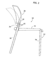
- the reference number 10 designates a chair with tiltable backrest according to the present invention.
- the chair 10 comprises a base structure 12 bearing a seat 14.
- the base structure 12 comprises two pairs of tubular elements 16 and 18 forming the front legs and the rear legs of the chair 10.
- the tubular elements 18 forming the rear legs are open at their top ends, which terminate substantially flush with the rear part of the seat 14.
- the chair 10 comprises a backrest 20 having two tubular side portions 22 open at their bottom ends and aligned to the tubular elements 18 of the base structure 12.
- the backrest 20 is constituted by a body made of plastic material with an arched shape.
- each elastic device 24 comprises a top support 26, a bottom support 28, and a flexurally deformable elastic element 30.
- the elastic element 30 can, for example, be constituted by a series of flexible metal plates 32 set alongside one another, each of the metal plates 32 having the shape of an elongated strip. Said arrangement is not, however, to be considered imperative. From the constructional standpoint, the elastic element 30 may be made in various ways provided that it has a desired flexural stiffness.
- the elastic element 30 has a top portion 30a fixed to the top support 26 and a bottom portion 30b fixed to the bottom support 28.
- the top support 26 and the bottom support 28 are each formed by a pair of shells 34, 36, set on opposite sides of the respective stretch of elastic element 30a, 30b.
- the shells 34, 36 are fixed to one another by means of respective rivets 38, 40, which extend through aligned holes of the side parts 34, 36 and of the elastic element 30.
- the side parts 34, 36 are made of metal material.
- the supports 34, 36 could in any case be obtained in another way; for example, said supports could be constituted by monolithic bodies with cavities, in which the respective stretches 30a, 30b of the elastic element 30 are received and fixed.
- the supports 34, 36 are substantially rigid and undeformable.
- the top support 26 of each elastic device 24 is inserted and fixed in a respective tubular portion 22 of the backrest 20.
- the support 28 is inserted and fixed in the corresponding tubular element 18 of the base structure 12. Fixing of the supports 26, 28 in the tubular portions 22, 18 can be obtained by force driving.
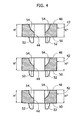
- Each elastic device 24 comprises a plurality of sectors 42 set on top of one another, which surround a central stretch 30c of the elastic element 30.
- the sectors 42 are contained between the bottom end of the top support 26 and the top end of the bottom support 28.
- the sectors 42 can be tilted with respect to one another so as to enable a deformation of the elastic device between a resting position illustrated in Figure 5 and a backwards deflected position illustrated in Figure 6 .
- a plurality of slits 46 are formed between each pair of adjacent sectors 42.
- the slits 46 are substantially orthogonal with respect to the longitudinal axis of the elastic element 30.
- the sectors 42 are formed by bodies separate from one another.
- the sectors have respective holes 44 aligned with respect to one another, through which the central stretch 30c of the elastic element 30 extends.
- each sector 42 has a top front surface 48 and a bottom front surface 50.
- the surfaces 48 and 50 on the front part of the sectors 42 are orthogonal to the axis of the hole 44, whilst in the rear part of the sector 42 said surfaces are inclined, so that each sector 42 has in the rear part a height H' smaller than the height H" of the same sector in its front part.
- each sector 42 has projecting formations 52 that engage corresponding cavities 54 of an adjacent sector.
- the projections 52 and the cavities 54 preferably have arched surfaces in mutual sliding contact.
- the front projections and cavities, which are complementary to one another have a geometry that is different from the rear projections and cavities, which are likewise complementary to one another.
- Figure 6 shows the elastic device 26 in the position of maximum backwards inclination.
- the elastic element 30 is bent backwards, and the supports 26, 28 are inclined with respect to one another.
- the rear parts of the surfaces 48, 50 are in contact with one another and prevent any further backwards inclination of the top support 26 with respect to the bottom support 28.
- the sectors 42 hence constitute end-of-travel arrests that define the position of maximum backwards inclination of the backrest 20.
- the thickness of the slits 46 vanishes, and slits are formed between each pair of adjacent sectors 42 in the front part of the elastic device 24.
- the sectors 42 are formed by sections set on top of one another of a monolithic body 56, provided in its rear part with a plurality of slits 46 that divide the adjacent sectors 42 from one another.
- the body 56 has a longitudinal hole 44, within which the central stretch 30c of the elastic element 30 extends.
- the internal ends of the slits 46 extend as far as the longitudinal hole 44.
- each pair of adjacent sectors 42 facing one another come into contact with one another, following upon a backwards bending of the elastic element 30, and form an arrest that defines the position of maximum backwards inclination of the backrest.
- the slits 46 are very thin and do not entail any risks of pinching for the user. Then the elastic device 24 according to the invention does not need any flexible covering of the area of bending. From the aesthetic standpoint, the array of sectors 42 forms an aesthetic and styling continuity with the tubular portion 22 of the backrest that is remarkable from the aesthetic standpoint.
- a further advantage of the solution according to the invention as compared to the one described in W0 91/03191 lies in the fact that the bending is no longer localized in a single point, but rather distributed along the plurality of sectors 42. This enables providing the user with a decidedly higher level of comfort as compared to the known solution.
Landscapes
- Chairs For Special Purposes, Such As Reclining Chairs (AREA)
Claims (8)
- Stuhl aufweisend:- eine Basisstruktur (12), welche einen Sitz (14) trägt, wobei die Basisstruktur (12) zwei rückseitige rohrförmige Elemente (18) beinhaltet, welche am oberen Ende offen sind;- eine Rückenlehne (20), welche zwei rohrförmige Bereiche (22) aufweist, welche unten offen sind und welche zu den rohrförmigen Elementen (18) der Basisstruktur (12) ausgerichtet sind; und- zwei elastische Bauteile (24), von denen jedes aufweisteine obere Halterung (26), welche in einen rohrförmigen Bereich (22) der Rückenlehne (20) eingebracht wird,
eine untere Halterung (28), welche in das zugehörige rohrförmige Element (18) der Basisstruktur (12) eingebracht ist, und
ein elastisches Element (30), welches einen oberen Abschnitt (30a) aufweist, der an der oberen Halterung (26) befestigt ist, und einen unteren Abschnitt (30b) aufweist, der an der unteren Halterung (28) befestigt ist, wobei das elastische Element (30) biegend verformbar ausgebildet ist, um ein Neigen zwischen der oberen Halterung (26) und der unteren Halterung (28) zu ermöglichen,
wobei in einer Ruheposition jedes elastische Element (30) geradlinig ist und die zwei Halterungen (26, 28) von allen elastischen Bauteilen (24) im Bezug zueinander fluchtend angeordnet sind, und
wobei in einer Position der maximalen Rückwärtsneigung jedes elastische Element (30) nach hinten gebogen ist und die beiden Halterungen (26, 28) von jedem elastischen Bauteil (24) im Bezug zueinander geneigt sind,
dadurch gekennzeichnet, dass
jedes der elastischen Bauteile (24) eine Mehrzahl von Sektoren (42) aufweist, welche aufeinander angeordnet sind und welche zwischen der oberen Halterung (26) und der unteren Halterung (28) angeordnet sind, wobei das elastische Element (30) einen zentralen Abschnitt (30c) aufweist, welcher sich durch die Sektoren (42) hindurch erstreckt, und wobei in der Ruheposition der elastischen Elemente (30) eine Mehrzahl von Schlitzen (46) auf der Rückseite von jedem elastischen Bauteil (24) zwischen jedem Paar von benachbarten Sektoren (42) ausgebildet ist, wobei in der Position der maximalen Rückwärtsneigung gegenüberliegende Oberfläche (48, 50) der Schlitze (46) miteinander in Berührung stehen und eine weitere Rückwärtsneigung der oberen Halterung (26) im Bezug zur unteren Halterung (28) unterbinden. - Stuhl gemäß Anspruch 1, dadurch gekennzeichnet, dass die Sektoren (42) durch separate Körper ausgebildet sind, welche übereinander gestapelt sind.
- Stuhl gemäß Anspruch 2, dadurch gekennzeichnet, dass jeder der Sektoren (42) einen hinteren Bereich mit einer Höhe (H') aufweist, welche geringer ist als die Höhe (H") eines vorderen Bereichs des selben Sektors.
- Stuhl gemäß Anspruch 2, dadurch gekennzeichnet, dass jeder der Sektoren (42) mit Vorsprüngen (52) ausgestattet ist, welche in Aussparungen eingreifen, die eine Form komplementär zu einem angrenzenden Sektor (42) aufweisen.
- Stuhl gemäß Anspruch 4, dadurch gekennzeichnet, dass die Vorsprünge (52) und die Aussparungen (54) gebogene Oberflächen aufweisen, welche in gegenseitigem gleitenden Kontakt stehen.
- Stuhl gemäß Anspruch 1, dadurch gekennzeichnet, dass die Sektoren (42) aus Bereichen eines langgestreckten monolithischen Körpers (56) gebildet sind, die aufeinander angeordnet sind.
- Stuhl gemäß Anspruch 1, dadurch gekennzeichnet, dass die obere Halterung (26) und die untere Halterung (28) jeweils aus einem Paar von Seitenteilen gebildet werden, welche aneinander auf gegenüberliegenden Seiten des oberen Abschnitts (30a) oder des unteren Abschnitts (30b) des elastischen Elements (30) befestigt sind.
- Stuhl gemäß Anspruch 1, dadurch gekennzeichnet, dass das elastische Element (30) eine Mehrzahl von langgestreckten Streifen aufweist, welche in Kontakt zueinander angeordnet sind.
Priority Applications (4)
| Application Number | Priority Date | Filing Date | Title |
|---|---|---|---|
| EP08425712A EP2183997B1 (de) | 2008-11-06 | 2008-11-06 | Stuhl mit kippbarer Rückenlehne |
| ES08425712T ES2371124T3 (es) | 2008-11-06 | 2008-11-06 | Silla con respaldo reclinable. |
| JP2009244168A JP5518426B2 (ja) | 2008-11-06 | 2009-10-23 | 傾動可能なバックレストを備えた椅子 |
| US12/612,959 US8282166B2 (en) | 2008-11-06 | 2009-11-05 | Chair with tiltable backrest |
Applications Claiming Priority (1)
| Application Number | Priority Date | Filing Date | Title |
|---|---|---|---|
| EP08425712A EP2183997B1 (de) | 2008-11-06 | 2008-11-06 | Stuhl mit kippbarer Rückenlehne |
Publications (2)
| Publication Number | Publication Date |
|---|---|
| EP2183997A1 EP2183997A1 (de) | 2010-05-12 |
| EP2183997B1 true EP2183997B1 (de) | 2011-08-17 |
Family
ID=40552032
Family Applications (1)
| Application Number | Title | Priority Date | Filing Date |
|---|---|---|---|
| EP08425712A Ceased EP2183997B1 (de) | 2008-11-06 | 2008-11-06 | Stuhl mit kippbarer Rückenlehne |
Country Status (4)
| Country | Link |
|---|---|
| US (1) | US8282166B2 (de) |
| EP (1) | EP2183997B1 (de) |
| JP (1) | JP5518426B2 (de) |
| ES (1) | ES2371124T3 (de) |
Families Citing this family (11)
| Publication number | Priority date | Publication date | Assignee | Title |
|---|---|---|---|---|
| KR101834468B1 (ko) * | 2010-05-18 | 2018-03-05 | 아리아 엔터프라이시스, 인크. | 휴대용 컴팩트 접이식 가구 부품들 |
| US8702171B2 (en) * | 2010-06-10 | 2014-04-22 | Knoll, Inc. | Article of furniture |
| KR101188543B1 (ko) * | 2010-11-19 | 2012-10-05 | 서원호 | 접이식 수강대를 갖는 의자 |
| ITTO20110375A1 (it) | 2011-04-29 | 2012-10-30 | Pro Cord Spa | Sedia con schienale oscillante |
| ITTO20130650A1 (it) | 2013-07-31 | 2015-02-01 | Pro Cord Spa | Sedia con schienale oscillante |
| ITTO20131015A1 (it) * | 2013-12-13 | 2015-06-14 | Pro Cord Spa | Sedia con schienale oscillante |
| ES2616536T3 (es) | 2014-05-22 | 2017-06-13 | Pro-Cord S.P.A. | Silla con respaldo inclinable |
| USD740044S1 (en) | 2014-06-06 | 2015-10-06 | Hni Technologies Inc. | Chair |
| US10667969B2 (en) | 2018-01-16 | 2020-06-02 | Kinetic Innovative Seating System Llc | Ergonomically designed seating apparatus |
| EP4241620B1 (de) | 2022-03-09 | 2025-04-09 | Pro-Cord S.p.A. | Stuhl mit schwenkbarer rückenlehne |
| US12336632B2 (en) * | 2022-10-03 | 2025-06-24 | Learfield Amplify Seating, Llc | Stadium seat |
Family Cites Families (13)
| Publication number | Priority date | Publication date | Assignee | Title |
|---|---|---|---|---|
| US2587822A (en) * | 1946-06-21 | 1952-03-04 | Walter D Corning | Resiliently mounted chair back |
| JPS5848429Y2 (ja) * | 1978-08-11 | 1983-11-05 | 株式会社伊藤喜工作所 | 椅子の背「もたれ」杆 |
| CH661967A5 (en) * | 1983-06-09 | 1987-08-31 | Intercollection Dev S A | Flexible supporting element and seat |
| US4549764A (en) * | 1983-09-14 | 1985-10-29 | K. L. Spring & Stamping Corporation | Flexible chair back |
| US4603904A (en) * | 1985-08-12 | 1986-08-05 | Shelby Williams Industries, Inc. | Chair with articulated, flexible spring backrest |
| US4787678A (en) * | 1988-01-25 | 1988-11-29 | Cushion Cut, Inc. | Outboard bearing support |
| US4869552A (en) * | 1988-09-14 | 1989-09-26 | Shelby Williams Industries, Inc. | Flexible backrest assembly for a chair |
| US5039163A (en) | 1988-09-14 | 1991-08-13 | Shelby Williams Industries, Inc. | Reinforced flexible backrest assembly for a chair |
| DE4224699A1 (de) * | 1992-07-25 | 1994-01-27 | Euwe Eugen Wexler Gmbh | Kunststoffgelenk zur gelenkigen Verbindung zweier Bauteile |
| US6328047B1 (en) * | 2000-07-19 | 2001-12-11 | Chorng-Cheng Lee | Position adjustment member of a sunshade |
| CN2462769Y (zh) * | 2001-01-11 | 2001-12-05 | 厦门进雄企业有限公司 | 椅背靠杆的角度自动调整装置 |
| WO2002069762A2 (en) * | 2001-02-23 | 2002-09-12 | Krueger International, Inc. | Flexible bar-type back pivot mounting arrangement for a chair |
| US20070287618A1 (en) * | 2006-05-31 | 2007-12-13 | Verheem Johann B | Abdominal exercise chair with flexible back bar and rotating seat |
-
2008
- 2008-11-06 EP EP08425712A patent/EP2183997B1/de not_active Ceased
- 2008-11-06 ES ES08425712T patent/ES2371124T3/es active Active
-
2009
- 2009-10-23 JP JP2009244168A patent/JP5518426B2/ja not_active Expired - Fee Related
- 2009-11-05 US US12/612,959 patent/US8282166B2/en active Active
Also Published As
| Publication number | Publication date |
|---|---|
| US20100109403A1 (en) | 2010-05-06 |
| JP5518426B2 (ja) | 2014-06-11 |
| US8282166B2 (en) | 2012-10-09 |
| JP2010110626A (ja) | 2010-05-20 |
| ES2371124T3 (es) | 2011-12-27 |
| EP2183997A1 (de) | 2010-05-12 |
Similar Documents
| Publication | Publication Date | Title |
|---|---|---|
| US8282166B2 (en) | Chair with tiltable backrest | |
| EP1952724B1 (de) | Stuhl mit deformierbarer Rückenlehne | |
| EP2497390B1 (de) | Stuhl mit neigbarer Rückenlehne | |
| EP2110051A1 (de) | Stuhl | |
| US6296308B1 (en) | Shape adjusting mechanism | |
| EP2092855A1 (de) | Rückenlehnenvorrichtung für stuhl | |
| EP2946694B1 (de) | Stuhl mit kippbarer rückenlehne | |
| JP5865170B2 (ja) | 可傾式の背もたれを備えた椅子 | |
| CN106659302A (zh) | 椅子的靠背及椅子 | |
| US20160157615A1 (en) | Chair with elastically-deformable seat and backrest | |
| EP3058848A1 (de) | Stuhl mit kippbarem sitz | |
| JP2015029904A (ja) | 傾動可能な背凭れを備えた椅子 | |
| US9107504B2 (en) | Reclining loop frame stacking / swivel chair | |
| EP4098150B1 (de) | Stuhl mit flexibler rückenlehne | |
| EP1167069A1 (de) | Griffstück und Schaft für Schreibgerät | |
| EP3245901B1 (de) | Stuhl mit elastisch verformbarem sitz und/oder rückenlehne | |
| KR200494995Y1 (ko) | 의자 등받이용 프레임의 보강구조 | |
| KR101198223B1 (ko) | 의자 구조체 | |
| JP4105483B2 (ja) | ランバーサポート装置 | |
| EP1656856A1 (de) | Sitzlehne mit vereinfachter Montage |
Legal Events
| Date | Code | Title | Description |
|---|---|---|---|
| PUAI | Public reference made under article 153(3) epc to a published international application that has entered the european phase |
Free format text: ORIGINAL CODE: 0009012 |
|
| 17P | Request for examination filed |
Effective date: 20091109 |
|
| AK | Designated contracting states |
Kind code of ref document: A1 Designated state(s): AT BE BG CH CY CZ DE DK EE ES FI FR GB GR HR HU IE IS IT LI LT LU LV MC MT NL NO PL PT RO SE SI SK TR |
|
| AX | Request for extension of the european patent |
Extension state: AL BA MK RS |
|
| AKX | Designation fees paid |
Designated state(s): DE ES GB IT PT |
|
| GRAP | Despatch of communication of intention to grant a patent |
Free format text: ORIGINAL CODE: EPIDOSNIGR1 |
|
| GRAS | Grant fee paid |
Free format text: ORIGINAL CODE: EPIDOSNIGR3 |
|
| GRAA | (expected) grant |
Free format text: ORIGINAL CODE: 0009210 |
|
| AK | Designated contracting states |
Kind code of ref document: B1 Designated state(s): DE ES GB IT PT |
|
| REG | Reference to a national code |
Ref country code: GB Ref legal event code: FG4D |
|
| REG | Reference to a national code |
Ref country code: DE Ref legal event code: R096 Ref document number: 602008008930 Country of ref document: DE Effective date: 20111117 |
|
| REG | Reference to a national code |
Ref country code: ES Ref legal event code: FG2A Ref document number: 2371124 Country of ref document: ES Kind code of ref document: T3 Effective date: 20111227 |
|
| PG25 | Lapsed in a contracting state [announced via postgrant information from national office to epo] |
Ref country code: PT Free format text: LAPSE BECAUSE OF FAILURE TO SUBMIT A TRANSLATION OF THE DESCRIPTION OR TO PAY THE FEE WITHIN THE PRESCRIBED TIME-LIMIT Effective date: 20111219 |
|
| PLBE | No opposition filed within time limit |
Free format text: ORIGINAL CODE: 0009261 |
|
| STAA | Information on the status of an ep patent application or granted ep patent |
Free format text: STATUS: NO OPPOSITION FILED WITHIN TIME LIMIT |
|
| 26N | No opposition filed |
Effective date: 20120521 |
|
| REG | Reference to a national code |
Ref country code: DE Ref legal event code: R097 Ref document number: 602008008930 Country of ref document: DE Effective date: 20120521 |
|
| PGFP | Annual fee paid to national office [announced via postgrant information from national office to epo] |
Ref country code: ES Payment date: 20141013 Year of fee payment: 7 Ref country code: GB Payment date: 20141105 Year of fee payment: 7 Ref country code: DE Payment date: 20141029 Year of fee payment: 7 |
|
| REG | Reference to a national code |
Ref country code: DE Ref legal event code: R119 Ref document number: 602008008930 Country of ref document: DE |
|
| GBPC | Gb: european patent ceased through non-payment of renewal fee |
Effective date: 20151106 |
|
| PG25 | Lapsed in a contracting state [announced via postgrant information from national office to epo] |
Ref country code: DE Free format text: LAPSE BECAUSE OF NON-PAYMENT OF DUE FEES Effective date: 20160601 Ref country code: GB Free format text: LAPSE BECAUSE OF NON-PAYMENT OF DUE FEES Effective date: 20151106 |
|
| PG25 | Lapsed in a contracting state [announced via postgrant information from national office to epo] |
Ref country code: ES Free format text: LAPSE BECAUSE OF NON-PAYMENT OF DUE FEES Effective date: 20151107 |
|
| PGFP | Annual fee paid to national office [announced via postgrant information from national office to epo] |
Ref country code: IT Payment date: 20191118 Year of fee payment: 12 |
|
| PG25 | Lapsed in a contracting state [announced via postgrant information from national office to epo] |
Ref country code: IT Free format text: LAPSE BECAUSE OF NON-PAYMENT OF DUE FEES Effective date: 20201106 |