EP2182293A1 - Cooking top with gas burner comprising a semi-permeable element - Google Patents
Cooking top with gas burner comprising a semi-permeable element Download PDFInfo
- Publication number
- EP2182293A1 EP2182293A1 EP10154093A EP10154093A EP2182293A1 EP 2182293 A1 EP2182293 A1 EP 2182293A1 EP 10154093 A EP10154093 A EP 10154093A EP 10154093 A EP10154093 A EP 10154093A EP 2182293 A1 EP2182293 A1 EP 2182293A1
- Authority
- EP
- European Patent Office
- Prior art keywords
- cooking top
- gas burner
- cooking
- top according
- flame
- Prior art date
- Legal status (The legal status is an assumption and is not a legal conclusion. Google has not performed a legal analysis and makes no representation as to the accuracy of the status listed.)
- Withdrawn
Links
Images


Classifications
-
- F—MECHANICAL ENGINEERING; LIGHTING; HEATING; WEAPONS; BLASTING
- F23—COMBUSTION APPARATUS; COMBUSTION PROCESSES
- F23D—BURNERS
- F23D14/00—Burners for combustion of a gas, e.g. of a gas stored under pressure as a liquid
- F23D14/02—Premix gas burners, i.e. in which gaseous fuel is mixed with combustion air upstream of the combustion zone
- F23D14/04—Premix gas burners, i.e. in which gaseous fuel is mixed with combustion air upstream of the combustion zone induction type, e.g. Bunsen burner
- F23D14/08—Premix gas burners, i.e. in which gaseous fuel is mixed with combustion air upstream of the combustion zone induction type, e.g. Bunsen burner with axial outlets at the burner head
-
- F—MECHANICAL ENGINEERING; LIGHTING; HEATING; WEAPONS; BLASTING
- F24—HEATING; RANGES; VENTILATING
- F24C—DOMESTIC STOVES OR RANGES ; DETAILS OF DOMESTIC STOVES OR RANGES, OF GENERAL APPLICATION
- F24C3/00—Stoves or ranges for gaseous fuels
- F24C3/08—Arrangement or mounting of burners
- F24C3/085—Arrangement or mounting of burners on ranges
-
- F—MECHANICAL ENGINEERING; LIGHTING; HEATING; WEAPONS; BLASTING
- F23—COMBUSTION APPARATUS; COMBUSTION PROCESSES
- F23D—BURNERS
- F23D2203/00—Gaseous fuel burners
- F23D2203/10—Flame diffusing means
- F23D2203/102—Flame diffusing means using perforated plates
-
- F—MECHANICAL ENGINEERING; LIGHTING; HEATING; WEAPONS; BLASTING
- F23—COMBUSTION APPARATUS; COMBUSTION PROCESSES
- F23D—BURNERS
- F23D2203/00—Gaseous fuel burners
- F23D2203/10—Flame diffusing means
- F23D2203/103—Flame diffusing means using screens
-
- F—MECHANICAL ENGINEERING; LIGHTING; HEATING; WEAPONS; BLASTING
- F23—COMBUSTION APPARATUS; COMBUSTION PROCESSES
- F23D—BURNERS
- F23D2203/00—Gaseous fuel burners
- F23D2203/10—Flame diffusing means
- F23D2203/105—Porous plates
-
- F—MECHANICAL ENGINEERING; LIGHTING; HEATING; WEAPONS; BLASTING
- F23—COMBUSTION APPARATUS; COMBUSTION PROCESSES
- F23D—BURNERS
- F23D2212/00—Burner material specifications
- F23D2212/10—Burner material specifications ceramic
- F23D2212/103—Fibres
-
- F—MECHANICAL ENGINEERING; LIGHTING; HEATING; WEAPONS; BLASTING
- F23—COMBUSTION APPARATUS; COMBUSTION PROCESSES
- F23D—BURNERS
- F23D2212/00—Burner material specifications
- F23D2212/20—Burner material specifications metallic
- F23D2212/201—Fibres
Definitions
- the present invention relates to a cooking top, in particular adapted to be used in a household environment, comprising at least one gas burner.
- the assembly consisting of flame divider and cap originates a so-called “cup” burner using, as primary air to be mixed with gas, the air being present above the cooking top, which enters the burner through access areas delimited by so-called “skirts", i.e. profiles suitably applied to the underside of the flame divider.
- cup flame it is meant a flame having a substantially radial propagation direction. If emitted at an insufficient height above the cooking top, it may cause a low-O 2 combustion resulting in the generation of a high level of unburnt products (CO and NO x ) and, due to the thermal content of the flame, it may lead to deformation and/or blackening of the portion of the cooking top surrounding the burner.
- the cup burner In order to obtain an adequate primary air flow toward the gas mixing area and to have such an amount of secondary air available as to obtain a low-CO and low-NO x combustion, the cup burner must reach a certain height above the cooking top wherein it is installed, and the pot supports must remain at a suitable height (between 15 and 20 mm) relative to the burner. In particular, the height of the cup burner is approximately 30 mm above the cooking top, so that it is necessary that the pot supports used on the cooking top reach a height of approximately 45 ö 50 mm above the cooking top.
- the general object of the present invention is to provide an improved cooking top compared to the prior art.
- the cooking top adapted to substantially attain said objects incorporates the features set out in the annexed claims, which form an integral part of the present description.
- the present invention is based on the idea of providing a cooking top which, to be cleaned, does not require the removal of any external components or, as an alternative, only requires a minimal removal of external components, so as to offer the users of the cooking top according to the present invention a substantial time saving and a considerable increase in the effectiveness of the cleaning treatment.
- said idea is implemented through a gas burner comprising a semi-permeable element (typically micro-perforated sheet or fibrous membrane or porous membrane) capable of withstanding high temperatures such as those generated by the combustion of a fuel gas and air; said semi-permeable element is permeable to fuel gas and to any mixture comprising fuel gas and air, and is substantially impermeable to liquids.
- a semi-permeable element typically micro-perforated sheet or fibrous membrane or porous membrane
- semi-permeable element it is meant, in the present description and in the annexed claims, an element which can be run through by flows of gaseous substances, such as an air-gas mixture, at the same time being capable of rejecting, totally or almost totally, any flow of liquid substances.
- the semi-permeable element is advantageously capable of ensuring that said liquid flows do not compromise the correct functionality of the gas burner, i.e. it is capable of ensuring that the gas burner can be lighted again should said liquid flows extinguish the flame.
- substantially impermeable to liquids it is meant, in the present description and in the annexed claims, an element which is capable of preventing, totally or almost totally, any liquids to flow through.
- said element is advantageously capable of ensuring that said liquid flows do not compromise the correct functionality of the gas burner, i.e. it is capable of ensuring that the gas burner can be lighted again should said liquid flows extinguish the flame.
- the semi-permeable element may typically be a micro-perforated sheet, or a fibrous membrane, in particular made of metal, metal alloy, ceramic or carbon fibers, or a porous membrane, in particular made of a ceramic material, a composite material or a metal material.
- Fig.1 illustrates a cooking top 1 according to the present invention, in particular a flush-mountable cooking top 1.
- the cooking top is so shaped as to comprise a box 7 closed on top by a covering element, specifically a substantially flat visible surface 30, on which a plurality of housing means is obtained, at least one of said housing means being preferably a hole adapted to accommodate a burner, in particular a gas burner 40 as shown in the sectional view of Fig.2 .
- the cooking top may also comprise pot supporting means 6, adapted to ensure an appropriate separation distance between the visible surface 30 of the cooking top 1 and a pot containing food to be cooked, as well as interface means 27 adapted to, among other things, allow to adjust and/or display the operating parameters of each burner.
- the interface means 27 shown in Fig.1 consist of a "touch control" interface, but they may also consist of a mechanical interface with on-off taps.
- the gas burner 40 illustrated in Fig.2 adapted to be installed in a cooking top 1 according to the present invention, comprises first means adapted to supply fuel gas to the gas burner and preferably comprising an injector 11, second means adapted to draw air inside the gas burner and preferably comprising a Venturi element 10, and third means adapted to mix fuel gas with air and/or to provide the combustion of fuel gas and/or any mixture comprising fuel gas and air, and preferably comprising a burner cup 20.
- Primary air is air mixed with fuel gas inside the gas burner 40
- secondary air is air added to the already formed air-gas mixture in the area outside the cooking top 1 surrounding the gas burner 40, which air provides the additional O 2 required for a proper combustion.
- the intakes 18A-18N for primary air access are obtained directly on the burner cup 20, specifically on the portion thereof being adjacent to the injector 11 and upstream of the Venturi element 10.
- the intakes 18A-18N obtained on the burner cup 20 are large enough to provide an adequate primary air flow through them.
- a primary air forced circulation system may be associated with the gas burner 40.
- a “crown flame” is a flame which propagates out of the gas burner 40 in a substantially radial direction relative to the axis of the gas burner 40, i.e. in a substantially tangential direction relative to the visible surface 30 of the cooking top 1.
- Some examples of crown flames are all those flames generated by gas burners comprising, as external components, a flame divider and a cap such as those known in the art.
- a “carpet flame” is a flame which propagates out of the gas burner 40 in a substantially axial direction relative to the axis of the gas burner 40, i.e.
- a carpet flame may be either a "total” carpet flame or a "perimetric” carpet flame, depending on whether it covers a geometric figure (generally a circle) entirely or it covers just the peripheral portion of said geometric figure (generally a circular crown).
- the flame divider means 9 may be connected to the visible surface 30 and/or to the burner 40; furthermore, they comprise at least one semi-permeable element 90, being permeable to fuel gas and to any mixture comprising fuel gas and air and being substantially impermeable to liquids, which may be a micro-perforated sheet, or a fibrous membrane made of metal, metal alloy, ceramic or carbon fibers, or a porous membrane made of a ceramic, composite or metal material.
- the semi-permeable element 90 is located on top of the third means of the gas burner 40, in particular on top of the burner cup 20.
- the flame divider means 9 and/or the semi-permeable element 90 have a substantially axially symmetric shape, the axis of the flame divider means 9 and/or of the semi-permeable element 90 preferably essentially coinciding with the axis of the third means of the gas burner 40.
- the flame divider means 9 also provide the functions of delimiting the internal environment of the gas burner 40 at the top and of allowing the flame generated by the combustion of the air-gas mixture to exit the gas burner 40 through the semi-permeable element 90.
- the semi-permeable element 90 may be required to have a number of specific properties, including:
- the flame divider means 9 comprise a sheet, in particular a metal or metal alloy sheet, which is characterized by being micro-perforated, i.e. by comprising a series of holes whose diameter is preferably equal to or smaller than the sheet thickness.
- the holes and the surrounding sheet form as a whole the semi-permeable element 90.
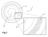
- Fig.3 shows, for the purpose of explaining said first embodiment of the present invention, an example of a micro-perforated sheet comprised in flame divider means 9 (which can be used with the gas burner 40 shown in Fig.2 ) and adapted to be used as a semi-permeable element 90.
- Fig.3 shows a detail of said micro-perforated sheet to illustrate a possible distribution of the holes in the semi-permeable element 90.
- the thickness of the micro-perforated sheet is preferably about 1 mm, so as to obtain a valid compromise between the mechanical strength of the micro-perforated sheet and the load losses undergone by the air-gas mixture flowing through the micro-perforated sheet. If the thickness is approximately 1 mm, the diameter of the holes of the micro-perforated sheet will be advantageously comprised between 100 ⁇ m and 1 mm.
- the flame divider means 9 comprise, as a semi-permeable element 90, a fibrous membrane made of e.g. metal, metal alloy, ceramic or carbon fibers, or a porous membrane made of e.g. a ceramic, composite or metal material, both of said membranes being able to ensure semi-permeability as well as an adequate gaseous flow and adequate thermal, mechanical and thermomechanical resistance.
- the most suitable membranes to be used in the cooking top 1 according to the present invention are membranes made out of woven, unwoven or partially woven metal fibers specifically designed for use near heat sources.
- a cooking top 1 which comprises at least one gas burner 40 and flame divider means 9 comprising a micro-perforated sheet used as a semi-permeable element 90. It is however clear that the following detailed description should be understood as an example which does not restrict the much broader inherent inventive concepts of the present invention. Likewise, it is clear that the advantages of the present invention remain unchanged if the micro-perforated sheet is replaced with a semi-permeable membrane made of metal or metal alloy fibers or of a ceramic or composite material.
- the micro-perforated sheet may be substantially discoidal in shape and essentially orthogonal to the axis of the gas burner 40.
- the holes obtained in the sheet may be through holes with axes essentially parallel to the axis of the gas burner 40: following the combustion of the air-gas mixture, this setup originates a carpet flame, i.e. a flame exiting the gas burner 40 in a substantially orthogonal direction relative to the visible surface 30 of the cooking top 1.
- the cooking top 1 according to the present invention differs from any prior-art household cooking top also because it produces a carpet flame instead of a crown flame.
- a carpet flame generally provides a higher yield than a crown flame, and also overcomes the latter's typical drawback of causing low-O 2 flames and/or blackening in the cooking top area surrounding the gas burner 40, if the flame is emitted at an insufficient height above the visible surface 30 of the cooking top 1.
- the flame divider means 9 and/or the semi-permeable element 90 are located essentially at the same level above the visible surface 30 of the cooking top 1.
- the pot supporting means 6 may reach a height being equal to or lower than 30 mm above the visible surface 30 of the cooking top 1, preferably a height comprised between 15 mm and 20 mm above the visible surface 30 of the cooking top 1, which is significantly lower than the height of about 45 ö 50 mm above the cooking top reached by pot supports used in prior-art cooking tops for domestic use with at least one gas burner.
- the flame divider means 9 comprising the previously described micro-perforated sheet, it is also possible to obtain a considerable lowering of the gas burner 40, which is also perfectly in agreement with the current design trends aiming at obtaining simple geometries with lines being as essential and harmonious as possible.
- the generation of a similar carpet flame and a resulting similar lowering of the burner may also be obtained by using, instead of a micro-perforated sheet, a semi-permeable membrane made of metal or metal alloy fibers or made of a ceramic or composite material.
- the flame divider means 9 comprising the micro-perforated sheet in particular, and the semi-permeable element 90 in general, may be secured in different alternative ways:
- the requirement of securing the membrane to the cooking top 1 may go side by side with the need of giving adequate strength to the membrane.
- the burner cup 20 it is possible to shape the burner cup 20 to comprise supporting means in its top area, on which the membrane is laid before being secured.
- said supporting means may consist of profiles extending on the inner surface of the burner cup 20 in a substantially radial direction, or of a grate connected to the burner cup 20 and lying in a plane essentially orthogonal to the axis of the gas burner 40.
- the semi-permeable element 90 has a substantially annular shape, which is considered to be particularly advantageous for at least one of the two following reasons:
- the semi-permeable element 90 consists of a micro-perforated sheet, it is possible to provide a distribution of the holes on the micro-perforated sheet according to which the holes are more densely distributed in the peripheral area than in the central area.
- the cooking top 1 also comprises at least one securing device 8, adapted to connect the flame divider means 9 to the cooking top 1 and/or to the gas burner 40.
- the flame divider means 9 comprise housing means adapted to house the securing device 8.
- the flame divider means 9 are so shaped as to have a hole 80 in their central area, preferably a circular hole whose axis essentially coincides with the axis of the gas burner 40. It is conceivable to exploit said central area of the flame divider means 9 to secure the flame divider means 9 to the cooking top 1 and/or to the gas burner 40 and to provide easy access to the internal components of the gas burner 40 for maintenance purposes.
- Said central hole 80 acts as a housing for the securing device 8 which, passing through it, is then secured by means of a removable connection, such as a screw-nut connection, to suitable supporting means 5A-5N comprised in the third means of the gas burner 40 (preferably made integral with the burner cup 20, e.g. through spot welding).
- the securing device 8 is a removable device and is therefore adapted to grant access to the inside of the gas burner 40 for maintaining the gas burner 40 and for allowing the flame divider means 9 and/or the semi-permeable element 90 to be removed easily.
- the securing device 8 comprises two parts: a first part 2 being substantially discoidal in shape and a second part 3 being substantially tubular in shape.
- the first part 2 has a larger diameter than the diameter of the central hole 80 of the flame divider means 9, whereas the second part 3 has a smaller diameter than the diameter of the central hole 80 and is fitted, on its side surface or at least a portion thereof, with anchoring means adapted to ensure a firm connection between the securing device 8 and the supporting means 5A-5N comprised in the third means of the gas burner 40.
- the flame divider means 9 are thus secured to the gas burner 40 because a portion of said flame divider means 9, in particular the portion surrounding the central hole 80, is interposed between the first part 2 of the securing device 8 and the supporting means 5A-5N in such a way as to prevent the air-gas mixture from flowing out between the flame divider means 9 and the securing device 8 as well as between the flame divider means 9 and the visible surface 30 of the cooking top 1. Since the connection between the securing device 8 and the supporting means 5A-5N is a removable connection, the embodiment of the present invention illustrated in Fig.2 ensures access inside the gas burner 40 for maintenance operations such as the replacement of the injector 11.
- the embodiment of the present invention illustrated in Fig.2 allows to remove the flame divider means 9 and/or the semi-permeable element 90 easily from the respective installation places, e.g. in order to wash them in a dishwasher, replace the flame divider means 9 and/or replace the semi-permeable element 90, in the event that these parts have suffered damage and are no longer operating properly.
- the second part 3 of the securing device 8 may be flared or have a decreasing section, reaching its minimum diameter on its free end.
- the flame divider means 9, comprising the semi-permeable element 90 may be advantageously associated with means adapted to divert said liquids toward areas wherein they cannot hinder the operation of the gas burner 40.
- diverter means one may use die-cast or forged profiles made of sheet-metal, brass, cast iron or steel, comprising holes adapted to allow gaseous substances to flow through (to supply the combustion of the gas burner 40) and having a diameter adapted to prevent said flow from suffering high load losses (e.g. the diameter of the holes of the diverter means may be about 500 ö 600 ⁇ m).
- the cooking top in particular the cooking top 1 comprising at least one gas burner 40, according to the present invention overcomes the inherent drawbacks of most cooking tops comprising at least one gas burner currently available on the market, since it is much easier to clean. It is also apparent that the generation of a carpet flame by the gas burner and the semi-permeable element 90 (micro-perforated sheet, metal or metal alloy fibrous membrane, or ceramic or composite membrane) as described offers the users of the cooking top 1 according to the present invention all the advantages which distinguish a carpet flame from a crown flame, as enunciated in the present description.
- the flame divider means 9 and/or the semi-permeable element 90 may have a substantially hollow cylindrical shape instead of a substantially discoidal shape and may be positioned on top of the gas burner 40 so as to allow the combustion air-gas mixture to flow out of the gas burner 40 in a substantially radial direction.
- the flame divider means do not delimit the gas burner 40 on top and may therefore be associated with covering means adapted to prevent the air-gas mixture from flowing out of the gas burner 40 axially and possibly also to make it easier for the air-gas mixture to reach the semi-permeable element 90.
- the inherent inventive concepts of the above description may also be used to generate an inclined flame, i.e. a flame which, when exiting the flame divider means 9 and/or the semi-permeable element 90, has a propagation direction not being parallel to either the visible surface 30 of the cooking top 1 (like a crown flame) or the axis of the gas burner 40 (like a carpet flame).
- a much innovative aspect of the present invention concerns the use of extended combustion areas inside of cooking tops, in particular for domestic use; said areas may, for example, be shaped as a circle, an ellipse, a polygon, a circular crown (as in the example of Fig.2 ), an elliptic crown, or a polygonal crown.
- a cooking top comprises at least one gas burner and respective flame divider means having a (burning) gas outlet area, as in the example of Fig. 2 , and comprising a micro-perforated sheet, a fibrous membrane, or a porous membrane.
- Said area may extend in a substantially horizontal direction (the horizontal direction being the direction in which the cooking top is adapted to be arranged), as in the example of Fig. 2 ; if the extension of said area were not horizontal, but inclined by an angle of e.g. 30° or 45° or 60°, the flame divider means would visibly protrude from the covering element of the cooking top (the visible surface 30 in the illustrated example).
- the flame divider means may be so provided as to produce a gaseous flow in a substantially vertical direction (the horizontal direction being the direction in which the cooking top is adapted to be arranged), i.e. directly toward the flat bottom of a cooking container.
- a cooking top using the "combustion area” concept may be fitted with one or several gas burners.
- the cooking top comprises just one burner and respective flame divider means, and the combustion area may substantially take up the entire cooking area of the cooking top.
- the cooking top comprises a plurality of cooking points, preferably two to six cooking points, and a corresponding plurality of burners and flame divider means having a corresponding plurality of spaced gas outlet areas.
Landscapes
- Engineering & Computer Science (AREA)
- Chemical & Material Sciences (AREA)
- Combustion & Propulsion (AREA)
- Mechanical Engineering (AREA)
- General Engineering & Computer Science (AREA)
- Gas Burners (AREA)
- Cookers (AREA)
- Separation Using Semi-Permeable Membranes (AREA)
Abstract
Description
- The present invention relates to a cooking top, in particular adapted to be used in a household environment, comprising at least one gas burner.
- At present, several typologies of cooking tops adapted to be used in a household environment are available on the market, the most widespread typology using one or more gas burners, wherein the amount of heat necessary for cooking food is generated through combustion of a gas appropriately mixed with air. Many gas burners currently installed in cooking tops for domestic use comprise two external components: a flame divider and a cap. The flame divider is usually made of die-cast aluminium and is adapted to generate a flame having a crown configuration, whereas the cap, usually made of enamelled cast iron (or brass alloy, or steel), acts as a flame divider closing element, thus preventing the air-gas mixture from flowing axially out of the burner. The assembly consisting of flame divider and cap originates a so-called "cup" burner using, as primary air to be mixed with gas, the air being present above the cooking top, which enters the burner through access areas delimited by so-called "skirts", i.e. profiles suitably applied to the underside of the flame divider.
- By "crown flame" it is meant a flame having a substantially radial propagation direction. If emitted at an insufficient height above the cooking top, it may cause a low-O2 combustion resulting in the generation of a high level of unburnt products (CO and NOx) and, due to the thermal content of the flame, it may lead to deformation and/or blackening of the portion of the cooking top surrounding the burner. In order to obtain an adequate primary air flow toward the gas mixing area and to have such an amount of secondary air available as to obtain a low-CO and low-NOx combustion, the cup burner must reach a certain height above the cooking top wherein it is installed, and the pot supports must remain at a suitable height (between 15 and 20 mm) relative to the burner. In particular, the height of the cup burner is approximately 30 mm above the cooking top, so that it is necessary that the pot supports used on the cooking top reach a height of approximately 45 ö 50 mm above the cooking top.
- Though the above-mentioned gas burners offer a number of advantages which promoted their large-scale diffusion, such as adaptability to different types of fuel gas and competitive industrial costs, they remain however very difficult to clean. As a matter of fact, many gas burners for domestic use currently available on the market require the removal of external components to be cleaned properly. Once cleaned separately, said external components must then be repositioned correctly in order to reassemble the gas burner. It follows that cleaning cooking tops available on the market today requires much time and generally gives bad results, also because of the very complex geometry of said external components, which hinders dirt removal.
- The general object of the present invention is to provide an improved cooking top compared to the prior art.
- It is a specific object of the present invention to overcome the above drawback through a cooking top with at least one innovative gas burner adapted to be preferably installed in a household environment.
- The cooking top adapted to substantially attain said objects incorporates the features set out in the annexed claims, which form an integral part of the present description.
- The present invention is based on the idea of providing a cooking top which, to be cleaned, does not require the removal of any external components or, as an alternative, only requires a minimal removal of external components, so as to offer the users of the cooking top according to the present invention a substantial time saving and a considerable increase in the effectiveness of the cleaning treatment.
- According to the present invention, said idea is implemented through a gas burner comprising a semi-permeable element (typically micro-perforated sheet or fibrous membrane or porous membrane) capable of withstanding high temperatures such as those generated by the combustion of a fuel gas and air; said semi-permeable element is permeable to fuel gas and to any mixture comprising fuel gas and air, and is substantially impermeable to liquids.
- By "semi-permeable" element it is meant, in the present description and in the annexed claims, an element which can be run through by flows of gaseous substances, such as an air-gas mixture, at the same time being capable of rejecting, totally or almost totally, any flow of liquid substances. In the event that liquid flows should manage to run through it, the semi-permeable element is advantageously capable of ensuring that said liquid flows do not compromise the correct functionality of the gas burner, i.e. it is capable of ensuring that the gas burner can be lighted again should said liquid flows extinguish the flame.
- By "substantially impermeable to liquids" it is meant, in the present description and in the annexed claims, an element which is capable of preventing, totally or almost totally, any liquids to flow through. In the event that liquid flows should manage to run through it, said element is advantageously capable of ensuring that said liquid flows do not compromise the correct functionality of the gas burner, i.e. it is capable of ensuring that the gas burner can be lighted again should said liquid flows extinguish the flame.
- The semi-permeable element may typically be a micro-perforated sheet, or a fibrous membrane, in particular made of metal, metal alloy, ceramic or carbon fibers, or a porous membrane, in particular made of a ceramic material, a composite material or a metal material.
- The present invention will become apparent, together with its further advantages, from the following detailed description and from the annexed drawings, which are supplied by way of non-limiting example, wherein:
-
Fig.1 schematically shows a detail of a cooking top which represents a possible embodiment of the present invention; -
Fig.2 is a schematic sectional view of a cooking top which represents a possible embodiment of the present invention
and -
Fig.3 schematically shows a possible embodiment of a component of acooking top 1 according to the present invention, in particular of the component called "flame divider means". -
Fig.1 illustrates acooking top 1 according to the present invention, in particular a flush-mountable cooking top 1. The cooking top is so shaped as to comprise abox 7 closed on top by a covering element, specifically a substantially flatvisible surface 30, on which a plurality of housing means is obtained, at least one of said housing means being preferably a hole adapted to accommodate a burner, in particular agas burner 40 as shown in the sectional view ofFig.2 . The cooking top may also comprise pot supportingmeans 6, adapted to ensure an appropriate separation distance between thevisible surface 30 of thecooking top 1 and a pot containing food to be cooked, as well as interface means 27 adapted to, among other things, allow to adjust and/or display the operating parameters of each burner. The interface means 27 shown inFig.1 consist of a "touch control" interface, but they may also consist of a mechanical interface with on-off taps. - The
gas burner 40 illustrated inFig.2 , adapted to be installed in acooking top 1 according to the present invention, comprises first means adapted to supply fuel gas to the gas burner and preferably comprising aninjector 11, second means adapted to draw air inside the gas burner and preferably comprising aVenturi element 10, and third means adapted to mix fuel gas with air and/or to provide the combustion of fuel gas and/or any mixture comprising fuel gas and air, and preferably comprising aburner cup 20. - More in detail:
- the first means operate as gas injection means and comprise in particular the injector 11 (which may be either vertical, i.e. with its axis parallel to the axis of the
burner cup 20, or horizontal, i.e. with its axis orthogonal to the axis of the burner cup 20), adapted to spread the gas inside thegas burner 40, and theinjector holder 12, adapted to connect theinjector 11 to the gas supply main; - the second means operate as means for drawing primary air inside the
gas burner 40 and as air-gas mixing means, and comprise in particular theintakes 18A-18N, adapted to allow primary air to flow inside thegas burner 40, and the Venturi element 10 (which may be either vertical, i.e. with its axis parallel to the axis of theburner cup 20, or horizontal, i.e. with its axis orthogonal to the axis of theburner cup 20, and which inFig.2 is connected to theburner cup 20 through the plate 15), adapted to create, inside thegas burner 40, a vacuum adapted to convey gas and primary air toward the mixing and/or combustion area
and - the third means operate as structural means and advantageously have a substantially axially symmetric shape, with an axis essentially orthogonal to the
visible surface 30 of thecooking top 1, and comprise in particular theburner cup 20, which is adapted to ensure a stable support for the other burner components on top of it and to delimit the area where the mixing of gas and primary air and/or the combustion of the air-gas mixture takes place. - It is now worth specifying the meaning of the terms "primary air" and "secondary air" as used in the present description. "Primary air" is air mixed with fuel gas inside the
gas burner 40, whereas "secondary air" is air added to the already formed air-gas mixture in the area outside thecooking top 1 surrounding thegas burner 40, which air provides the additional O2 required for a proper combustion. According to an advantageous embodiment of thecooking top 1 according to the present invention, theintakes 18A-18N for primary air access are obtained directly on theburner cup 20, specifically on the portion thereof being adjacent to theinjector 11 and upstream of the Venturielement 10. In order to ensure a stoichiometrically correct mixture of gas and primary air in accordance with the combustion process the mixture will be subjected to, theintakes 18A-18N obtained on theburner cup 20 are large enough to provide an adequate primary air flow through them. In the event that natural circulation does not guarantee a sufficient primary air flow rate to properly supply air to thegas burner 40, a primary air forced circulation system may be associated with thegas burner 40. - The terms "crown flame" and "carpet flame" will also be used in the present description. A "crown flame" is a flame which propagates out of the
gas burner 40 in a substantially radial direction relative to the axis of thegas burner 40, i.e. in a substantially tangential direction relative to thevisible surface 30 of thecooking top 1. Some examples of crown flames are all those flames generated by gas burners comprising, as external components, a flame divider and a cap such as those known in the art. A "carpet flame", on the other hand, is a flame which propagates out of thegas burner 40 in a substantially axial direction relative to the axis of thegas burner 40, i.e. in a substantially orthogonal direction relative to thevisible surface 30 of thecooking top 1. A carpet flame may be either a "total" carpet flame or a "perimetric" carpet flame, depending on whether it covers a geometric figure (generally a circle) entirely or it covers just the peripheral portion of said geometric figure (generally a circular crown). - The flame divider means 9 may be connected to the
visible surface 30 and/or to theburner 40; furthermore, they comprise at least onesemi-permeable element 90, being permeable to fuel gas and to any mixture comprising fuel gas and air and being substantially impermeable to liquids, which may be a micro-perforated sheet, or a fibrous membrane made of metal, metal alloy, ceramic or carbon fibers, or a porous membrane made of a ceramic, composite or metal material. Thesemi-permeable element 90 is located on top of the third means of thegas burner 40, in particular on top of theburner cup 20. Advantageously, the flame divider means 9 and/or thesemi-permeable element 90 have a substantially axially symmetric shape, the axis of the flame divider means 9 and/or of thesemi-permeable element 90 preferably essentially coinciding with the axis of the third means of thegas burner 40. The flame divider means 9 also provide the functions of delimiting the internal environment of thegas burner 40 at the top and of allowing the flame generated by the combustion of the air-gas mixture to exit thegas burner 40 through thesemi-permeable element 90. - The
semi-permeable element 90 may be required to have a number of specific properties, including: - permeability to a gas and to air-gas mixtures, said gas being preferably a natural fuel gas such as CH4, or a liquefied fuel gas like LPG, or an artificial fuel gas like the so-called "town gas", obtained through gasification of liquid or solid fuels, or any other fuel among those used in the different countries;
- total or essentially total impermeability to liquid substances, which cannot prevent the ignition of the
gas burner 40 even when overflowing from a container having a certain height (which can be assumed to be 250 mm); - appropriate porosity to ensure the above-described semi-permeability and at the same time to cause low load losses to the flows of gas or air-gas mixtures going through the
semi-permeable element 90, so that they can flow out of thegas burner 40 at an adequate velocity to ensure flame stability during the combustion (e.g. for air-CH4 mixtures, said velocity is preferably comprised between 1.5 m/s and 3 m/s); - high thermal resistance, which prevents the
semi-permeable element 90 from suffering evident deformation when run through by the flame; - sufficient mechanical strength to prevent the
semi-permeable element 90 from suffering evident deformation should it undergo an accidental impact, e.g. against a cooking container, or should it fall down during maintenance operations, and to prevent it from suffering evident abrasion during cleaning operations; - sufficient thermomechanical strength to ensure that any deformation suffered by the
semi-permeable element 90 should it come in contact with an overflowing liquid having a different temperature is minimal
and/or - adequate surface finish to properly integrate said
semi-permeable element 90 in or with the flame divider means 9 and with thecooking top 1 whereon the burner is installed, without evident blackening of saidsemi-permeable element 90 during the operation of thegas burner 40. - According to a first possible embodiment of the present invention, the flame divider means 9 comprise a sheet, in particular a metal or metal alloy sheet, which is characterized by being micro-perforated, i.e. by comprising a series of holes whose diameter is preferably equal to or smaller than the sheet thickness. The holes and the surrounding sheet form as a whole the
semi-permeable element 90.Fig.3 shows, for the purpose of explaining said first embodiment of the present invention, an example of a micro-perforated sheet comprised in flame divider means 9 (which can be used with thegas burner 40 shown inFig.2 ) and adapted to be used as asemi-permeable element 90. Furthermore, the enlargement annexed toFig.3 shows a detail of said micro-perforated sheet to illustrate a possible distribution of the holes in thesemi-permeable element 90. The thickness of the micro-perforated sheet is preferably about 1 mm, so as to obtain a valid compromise between the mechanical strength of the micro-perforated sheet and the load losses undergone by the air-gas mixture flowing through the micro-perforated sheet. If the thickness is approximately 1 mm, the diameter of the holes of the micro-perforated sheet will be advantageously comprised between 100 µm and 1 mm. - According to a second possible embodiment of the present invention, the flame divider means 9 comprise, as a
semi-permeable element 90, a fibrous membrane made of e.g. metal, metal alloy, ceramic or carbon fibers, or a porous membrane made of e.g. a ceramic, composite or metal material, both of said membranes being able to ensure semi-permeability as well as an adequate gaseous flow and adequate thermal, mechanical and thermomechanical resistance. In particular, the most suitable membranes to be used in thecooking top 1 according to the present invention are membranes made out of woven, unwoven or partially woven metal fibers specifically designed for use near heat sources. Many examples of the above metal fiber membranes can be found in the patent literature: by way of example and not by way of limitation, it can be stated that the most suitable membranes to be used in thecooking top 1 according to the present invention are those described in patent applicationsWO94/14608 WO95/27871 WO02/99173 - In the present description a
cooking top 1 according to the present invention will be illustrated in detail, which comprises at least onegas burner 40 and flame divider means 9 comprising a micro-perforated sheet used as asemi-permeable element 90. It is however clear that the following detailed description should be understood as an example which does not restrict the much broader inherent inventive concepts of the present invention. Likewise, it is clear that the advantages of the present invention remain unchanged if the micro-perforated sheet is replaced with a semi-permeable membrane made of metal or metal alloy fibers or of a ceramic or composite material. - The micro-perforated sheet may be substantially discoidal in shape and essentially orthogonal to the axis of the
gas burner 40. Moreover, the holes obtained in the sheet may be through holes with axes essentially parallel to the axis of the gas burner 40: following the combustion of the air-gas mixture, this setup originates a carpet flame, i.e. a flame exiting thegas burner 40 in a substantially orthogonal direction relative to thevisible surface 30 of thecooking top 1. According to this embodiment, thecooking top 1 according to the present invention differs from any prior-art household cooking top also because it produces a carpet flame instead of a crown flame. A carpet flame generally provides a higher yield than a crown flame, and also overcomes the latter's typical drawback of causing low-O2 flames and/or blackening in the cooking top area surrounding thegas burner 40, if the flame is emitted at an insufficient height above thevisible surface 30 of thecooking top 1. - In the
cooking top 1 according to the present invention, the flame divider means 9 and/or thesemi-permeable element 90 are located essentially at the same level above thevisible surface 30 of thecooking top 1. Furthermore, the pot supporting means 6 may reach a height being equal to or lower than 30 mm above thevisible surface 30 of thecooking top 1, preferably a height comprised between 15 mm and 20 mm above thevisible surface 30 of thecooking top 1, which is significantly lower than the height of about 45 ö 50 mm above the cooking top reached by pot supports used in prior-art cooking tops for domestic use with at least one gas burner. Thanks to this configuration of the flame divider means 9 comprising the previously described micro-perforated sheet, it is also possible to obtain a considerable lowering of thegas burner 40, which is also perfectly in agreement with the current design trends aiming at obtaining simple geometries with lines being as essential and harmonious as possible. The generation of a similar carpet flame and a resulting similar lowering of the burner may also be obtained by using, instead of a micro-perforated sheet, a semi-permeable membrane made of metal or metal alloy fibers or made of a ceramic or composite material. - The flame divider means 9 comprising the micro-perforated sheet in particular, and the
semi-permeable element 90 in general, may be secured in different alternative ways: - first the
gas burner 40 is secured to thecooking top 1, and then the flame divider means 9 are applied together with the micro-perforated sheet by removably or irremovably securing said means to thecooking top 1; - first the flame divider means 9 are removably or irremovably secured to the third means of the
gas burner 40, and then the burner is secured to the cooking top
or - the flame divider means 9 are obtained in one piece with another burner component, e.g. with the
burner cup 20 appropriately shaped to comprise also an upper surface adapted to be used as a semi-permeable element 90 (e.g. adapted to be subjected to a micro-perforation treatment). - If a semi-permeable membrane is used, made of metal or metal alloy fibers or of a ceramic or composite material, the requirement of securing the membrane to the
cooking top 1 may go side by side with the need of giving adequate strength to the membrane. In such a case, it is possible to shape theburner cup 20 to comprise supporting means in its top area, on which the membrane is laid before being secured. By way of example, said supporting means may consist of profiles extending on the inner surface of theburner cup 20 in a substantially radial direction, or of a grate connected to theburner cup 20 and lying in a plane essentially orthogonal to the axis of thegas burner 40. - According to an embodiment of the present invention, the
semi-permeable element 90 has a substantially annular shape, which is considered to be particularly advantageous for at least one of the two following reasons: - secondary air is drawn with more difficulty in the central area than in the peripheral area, so that in the central area of the
semi-permeable element 90 the combustion of the air-gas mixture may be imperfect, thus generating unburnt products (whose presence is indicated by so-called "yellow tips" on flame ends)
and - generating a flame in the peripheral area of the
semi-permeable element 90 means producing an extended flame which provides adequate heat distribution in the area above thegas burner 40 during the food cooking process. - If the
semi-permeable element 90 consists of a micro-perforated sheet, it is possible to provide a distribution of the holes on the micro-perforated sheet according to which the holes are more densely distributed in the peripheral area than in the central area. - According to the embodiment of the present invention illustrated in
Fig.2 , thecooking top 1 also comprises at least onesecuring device 8, adapted to connect the flame divider means 9 to thecooking top 1 and/or to thegas burner 40. The flame divider means 9 comprise housing means adapted to house the securingdevice 8. The flame divider means 9 are so shaped as to have ahole 80 in their central area, preferably a circular hole whose axis essentially coincides with the axis of thegas burner 40. It is conceivable to exploit said central area of the flame divider means 9 to secure the flame divider means 9 to thecooking top 1 and/or to thegas burner 40 and to provide easy access to the internal components of thegas burner 40 for maintenance purposes. Saidcentral hole 80 acts as a housing for the securingdevice 8 which, passing through it, is then secured by means of a removable connection, such as a screw-nut connection, to suitable supporting means 5A-5N comprised in the third means of the gas burner 40 (preferably made integral with theburner cup 20, e.g. through spot welding). The securingdevice 8 is a removable device and is therefore adapted to grant access to the inside of thegas burner 40 for maintaining thegas burner 40 and for allowing the flame divider means 9 and/or thesemi-permeable element 90 to be removed easily. - Preferably, the securing
device 8 comprises two parts: afirst part 2 being substantially discoidal in shape and asecond part 3 being substantially tubular in shape. Thefirst part 2 has a larger diameter than the diameter of thecentral hole 80 of the flame divider means 9, whereas thesecond part 3 has a smaller diameter than the diameter of thecentral hole 80 and is fitted, on its side surface or at least a portion thereof, with anchoring means adapted to ensure a firm connection between the securingdevice 8 and the supporting means 5A-5N comprised in the third means of thegas burner 40. The flame divider means 9 are thus secured to thegas burner 40 because a portion of said flame divider means 9, in particular the portion surrounding thecentral hole 80, is interposed between thefirst part 2 of the securingdevice 8 and the supporting means 5A-5N in such a way as to prevent the air-gas mixture from flowing out between the flame divider means 9 and the securingdevice 8 as well as between the flame divider means 9 and thevisible surface 30 of thecooking top 1. Since the connection between the securingdevice 8 and the supporting means 5A-5N is a removable connection, the embodiment of the present invention illustrated inFig.2 ensures access inside thegas burner 40 for maintenance operations such as the replacement of theinjector 11. Furthermore, the embodiment of the present invention illustrated inFig.2 allows to remove the flame divider means 9 and/or thesemi-permeable element 90 easily from the respective installation places, e.g. in order to wash them in a dishwasher, replace the flame divider means 9 and/or replace thesemi-permeable element 90, in the event that these parts have suffered damage and are no longer operating properly. - It may be particularly useful to provide the
securing device 8 with flow diverter means 4, adapted to help the air-gas mixture exiting theVenturi element 10 to reach the semi-permeable element 90: for this purpose, thesecond part 3 of the securingdevice 8 may be flared or have a decreasing section, reaching its minimum diameter on its free end. - Since the
semi-permeable element 90, according to the present invention, may also be run through by a small quantity of liquids (which however must be such as not to prevent a subsequent ignition of thegas burner 40 should the flame be extinguished), the flame divider means 9, comprising thesemi-permeable element 90, may be advantageously associated with means adapted to divert said liquids toward areas wherein they cannot hinder the operation of thegas burner 40. As diverter means, one may use die-cast or forged profiles made of sheet-metal, brass, cast iron or steel, comprising holes adapted to allow gaseous substances to flow through (to supply the combustion of the gas burner 40) and having a diameter adapted to prevent said flow from suffering high load losses (e.g. the diameter of the holes of the diverter means may be about 500 ö 600 µm). - It is apparent from the present description that the cooking top, in particular the
cooking top 1 comprising at least onegas burner 40, according to the present invention overcomes the inherent drawbacks of most cooking tops comprising at least one gas burner currently available on the market, since it is much easier to clean. It is also apparent that the generation of a carpet flame by the gas burner and the semi-permeable element 90 (micro-perforated sheet, metal or metal alloy fibrous membrane, or ceramic or composite membrane) as described offers the users of thecooking top 1 according to the present invention all the advantages which distinguish a carpet flame from a crown flame, as enunciated in the present description. However, said generation of a carpet flame must not be considered to be a fundamental element of the present invention, since the inherent inventive concepts of the present invention may also be used to generate a crown flame instead of a carpet flame. For this purpose, the flame divider means 9 and/or the semi-permeable element 90 (micro-perforated sheet, metal or metal alloy fiber membrane, or ceramic or composite membrane) may have a substantially hollow cylindrical shape instead of a substantially discoidal shape and may be positioned on top of thegas burner 40 so as to allow the combustion air-gas mixture to flow out of thegas burner 40 in a substantially radial direction. In this case, the flame divider means do not delimit thegas burner 40 on top and may therefore be associated with covering means adapted to prevent the air-gas mixture from flowing out of thegas burner 40 axially and possibly also to make it easier for the air-gas mixture to reach thesemi-permeable element 90. The inherent inventive concepts of the above description may also be used to generate an inclined flame, i.e. a flame which, when exiting the flame divider means 9 and/or thesemi-permeable element 90, has a propagation direction not being parallel to either thevisible surface 30 of the cooking top 1 (like a crown flame) or the axis of the gas burner 40 (like a carpet flame). - A much innovative aspect of the present invention concerns the use of extended combustion areas inside of cooking tops, in particular for domestic use; said areas may, for example, be shaped as a circle, an ellipse, a polygon, a circular crown (as in the example of
Fig.2 ), an elliptic crown, or a polygonal crown. Such a cooking top comprises at least one gas burner and respective flame divider means having a (burning) gas outlet area, as in the example ofFig. 2 , and comprising a micro-perforated sheet, a fibrous membrane, or a porous membrane. - Said area may extend in a substantially horizontal direction (the horizontal direction being the direction in which the cooking top is adapted to be arranged), as in the example of
Fig. 2 ; if the extension of said area were not horizontal, but inclined by an angle of e.g. 30° or 45° or 60°, the flame divider means would visibly protrude from the covering element of the cooking top (thevisible surface 30 in the illustrated example). - The flame divider means may be so provided as to produce a gaseous flow in a substantially vertical direction (the horizontal direction being the direction in which the cooking top is adapted to be arranged), i.e. directly toward the flat bottom of a cooking container.
- A cooking top using the "combustion area" concept may be fitted with one or several gas burners.
- In the former case, the cooking top comprises just one burner and respective flame divider means, and the combustion area may substantially take up the entire cooking area of the cooking top.
- In the latter case, the cooking top comprises a plurality of cooking points, preferably two to six cooking points, and a corresponding plurality of burners and flame divider means having a corresponding plurality of spaced gas outlet areas.
- The present invention has been described with reference to a particular embodiment example, but it is clear that many changes may be made thereto by those skilled in the art without departing from the scope defined by the annexed claims.
Claims (15)
- Cooking top (1) adapted in particular to be used in a household environment and adapted to be arranged in a substantially horizontal position, characterized by comprising at least one gas burner (40) and respective flame divider means (9) provided with a gas outlet area and comprising a micro-perforated sheet or a fibrous membrane or a porous membrane.
- Cooking top according to claim 1, characterized in that said area extends in a substantially horizontal direction.
- Cooking top according to claim 1 or 2, characterized in that said flame divider means are so provided as to produce a gaseous flow flowing out through said area in a substantially vertical direction.
- Cooking top according to any of claims 1 to 3, characterized by comprising a plurality of cooking points, preferably two to six cooking points, and a corresponding plurality of burners and flame divider means having a corresponding plurality of spaced gas outlet areas.
- Cooking top according to any of the preceding claims, characterized in that it comprises micro-perforated sheet having holes which are more densely distributed in a peripheral area than in a central area of said micro-perforated sheet.
- Cooking top according to any of the preceding claims, characterized in that it comprises micro-perforated sheet having holes whose diameter is equal to or smaller than the thickness of said sheet, the diameter of said holes being preferably comprised between 100 µm and 1 mm when the thickness of said sheet is approximately 1 mm.
- Cooking top according to any of the preceding claims, characterized in that it comprises micro-perforated sheet having holes with axes essentially parallel to the axis of said gas burner (40).
- Cooking top according to any of the preceding claims, characterized in that said flame divider means (9) are located essentially at the same level above a covering element (30) of the cooking top.
- Cooking top according to any of the preceding claims, characterized in that said micro-perforated sheet may be substantially discoidal in shape and essentially orthogonal to the axis of the gas burner (40)
- Cooking top according to any of the preceding claims, characterized by comprising a pot supporting means (6) which reach a height being equal to or lower than 30 mm above a visible surface (30) of said cooking top (1), preferably a height comprised between 15 mm and 20 mm.
- Cooking top according to any of the preceding claims, characterized by comprising an extended combustion area shaped as a circle or as an ellipse or as a polygon.
- Cooking top according to any of the preceding claims, characterized in that said flame divider means (9) are connected to said at least one gas burner (40) or to a covering element (30) of the cooking top.
- Cooking top according to any of the preceding claims, characterized in that said flame divider means (9) are obtained in one piece with another component of said at least one gas burner (40), in particular with a burner cup (20) of said at least one gas burner (40).
- Cooking top according to any of the preceding claims, characterized in that said at least one gas burner (9) comprises a Venturi element, said Venturi element being horizontal.
- Cooking top according to any of the preceding claims, characterized in that said flame divider means (9) are associated with diverter means comprising holes adapted to allow gaseous substances to flow through and adapted to divert liquids toward areas wherein they cannot hinder the operation of the gas burner (40), said holes of said diverter means preferably having a diameter about 500 ö 600 µm.
Applications Claiming Priority (2)
| Application Number | Priority Date | Filing Date | Title |
|---|---|---|---|
| IT000685A ITTO20050685A1 (en) | 2005-09-30 | 2005-09-30 | COOKTOP WITH GAS BURNER INCLUDING A SEMIPERMEABLE ELEMENT |
| EP06795174.9A EP1934532B1 (en) | 2005-09-30 | 2006-07-28 | Cooking top with gas burner comprising a semi-permeable element |
Related Parent Applications (2)
| Application Number | Title | Priority Date | Filing Date |
|---|---|---|---|
| EP06795174.9 Division | 2006-07-28 | ||
| EP06795174.9A Division-Into EP1934532B1 (en) | 2005-09-30 | 2006-07-28 | Cooking top with gas burner comprising a semi-permeable element |
Publications (1)
| Publication Number | Publication Date |
|---|---|
| EP2182293A1 true EP2182293A1 (en) | 2010-05-05 |
Family
ID=37745599
Family Applications (2)
| Application Number | Title | Priority Date | Filing Date |
|---|---|---|---|
| EP10154093A Withdrawn EP2182293A1 (en) | 2005-09-30 | 2006-07-28 | Cooking top with gas burner comprising a semi-permeable element |
| EP06795174.9A Expired - Lifetime EP1934532B1 (en) | 2005-09-30 | 2006-07-28 | Cooking top with gas burner comprising a semi-permeable element |
Family Applications After (1)
| Application Number | Title | Priority Date | Filing Date |
|---|---|---|---|
| EP06795174.9A Expired - Lifetime EP1934532B1 (en) | 2005-09-30 | 2006-07-28 | Cooking top with gas burner comprising a semi-permeable element |
Country Status (7)
| Country | Link |
|---|---|
| US (1) | US8662069B2 (en) |
| EP (2) | EP2182293A1 (en) |
| JP (1) | JP5064397B2 (en) |
| CN (1) | CN101278154B (en) |
| EA (1) | EA011985B1 (en) |
| IT (1) | ITTO20050685A1 (en) |
| WO (1) | WO2007036772A1 (en) |
Cited By (4)
| Publication number | Priority date | Publication date | Assignee | Title |
|---|---|---|---|---|
| WO2013113497A3 (en) * | 2012-02-01 | 2014-01-23 | Sabaf S.P.A. | A gas burner for a domestic cooktop |
| AU2013205632B2 (en) * | 2012-02-01 | 2015-12-24 | Sabaf S.P.A. | A gas burner for domestic cooktop |
| EP2864703A4 (en) * | 2012-06-26 | 2016-03-02 | Daniel H Lowry | Simmer plate for commercial and residential stoves |
| USD796900S1 (en) | 2015-12-17 | 2017-09-12 | Dan Lowry Llc | Heat diffuser |
Families Citing this family (33)
| Publication number | Priority date | Publication date | Assignee | Title |
|---|---|---|---|---|
| ITTO20070644A1 (en) | 2007-09-12 | 2009-03-13 | Indesit Co Spa | METHOD FOR ADJUSTING THE OPENING OF A VALVE FOR GAS-COOKED EDELECTRODUCTURE FLUID THAT USES IT |
| ITTO20080292A1 (en) | 2008-04-15 | 2009-10-16 | Indesit Co Spa | DOMESTIC COOKING SYSTEM INCLUDING A WALL UNIT |
| ITTO20080299A1 (en) * | 2008-04-16 | 2009-10-17 | Indesit Co Spa | MODULAR COOKTOP |
| EP2246619B1 (en) * | 2009-04-30 | 2015-08-19 | Electrolux Home Products Corporation N.V. | Vertical flame burner |
| IT1396781B1 (en) * | 2009-11-18 | 2012-12-14 | Indesit Co Spa | STOVE. |
| ITTO20100288A1 (en) * | 2010-04-13 | 2011-10-14 | Indesit Co Spa | BURNER FOR COOKING HOB, COOKTOP INCLUDING THIS BURNER AND METHOD FOR ITS MANUFACTURE. |
| IT1399558B1 (en) | 2010-04-13 | 2013-04-19 | Indesit Co Spa | REFINED COOKING APPLIANCE. |
| ITTO20100287A1 (en) | 2010-04-13 | 2011-10-14 | Indesit Co Spa | BURNER FOR STOVE, COOKING SYSTEM INCLUDING THIS BURNER AND METHOD FOR ITS MANUFACTURE. |
| IT1399560B1 (en) | 2010-04-13 | 2013-04-19 | Indesit Co Spa | ASSEMBLY METHOD OF A COOKING PLAN FOR HOME USE. |
| ITAN20120036A1 (en) * | 2011-04-19 | 2012-10-20 | Somipress Societa Metalli Iniett Ati S P A | GAS STOVE WITH FLAME TOWARDS THE INSIDE. |
| WO2013065018A2 (en) | 2011-11-03 | 2013-05-10 | Indesit Company S.P.A. | Gas burner, in particular for a cooking appliance |
| ES2621792T3 (en) * | 2011-11-04 | 2017-07-05 | Electrolux Home Products Corporation N.V. | Gas burner set, gas hob and appliance with gas burners |
| ITAN20120142A1 (en) * | 2011-11-04 | 2013-05-05 | Somipress Societa Metalli Iniett Ati S P A | GAS STOVE WITH FLAME TOWARDS THE INSIDE. |
| DE102012216079A1 (en) * | 2012-09-11 | 2014-03-13 | BSH Bosch und Siemens Hausgeräte GmbH | Cooking field arrangement for heating e.g. larger or smaller pot, has series parts extending on predetermined circular curves that limit surface portions, and partly overlapping surface portions, and mixing chambers attached below plate |
| FR2999276B1 (en) * | 2012-12-10 | 2014-12-12 | Applic Gaz Sa | GAS BURNER COMPRISING A BURNER HEAD |
| NL2011286C2 (en) | 2013-08-09 | 2015-02-10 | Intell Properties B V | GAS BURNER |
| WO2016094705A1 (en) * | 2014-12-10 | 2016-06-16 | Hestan Commercial Corporation | Cooking range |
| EP3056810B1 (en) * | 2015-02-11 | 2019-04-10 | Electrolux Appliances Aktiebolag | A gas burner assembly |
| EP3298330B1 (en) * | 2015-05-19 | 2019-07-03 | Somipress - Societa ' Metalli Iniettati S.R.L. | Double flame crown gas burner |
| EP3128235A1 (en) | 2015-08-03 | 2017-02-08 | Indesit Company S.p.A. | Gas burner, in particular for a cooking top for household use |
| EP3128237A1 (en) * | 2015-08-03 | 2017-02-08 | Indesit Company S.p.A. | System of gas burners, in particular for a cooking top for household use |
| US10827878B2 (en) * | 2016-10-25 | 2020-11-10 | Gmg Products, Llc. | Pizza oven accessory for barbecue grill |
| US10627113B2 (en) * | 2016-12-29 | 2020-04-21 | Whirlpool Corporation | Distributed vertical flame burner |
| EP3361154B1 (en) * | 2017-02-14 | 2021-03-17 | Electrolux Professional S.p.A. | Gas stove arrangement with a wok support and a gas burner top |
| ES2784615A1 (en) * | 2019-03-25 | 2020-09-29 | Bsh Electrodomesticos Espana Sa | Gas hob (Machine-translation by Google Translate, not legally binding) |
| US11988379B2 (en) | 2020-06-12 | 2024-05-21 | Bsh Home Appliances Corporation | Burner for a cooking appliance |
| CN112664934A (en) * | 2021-01-14 | 2021-04-16 | 湖南中创节能科技有限公司 | Fire hole assembly with micro-hole formed by micro-bead filler and furnace end |
| CN113503542A (en) * | 2021-07-06 | 2021-10-15 | 张英华 | Carbon fiber alloy fire cover and fire cover of gas stove and manufacturing method |
| RU210455U1 (en) * | 2021-12-21 | 2022-04-15 | федеральное государственное бюджетное образовательное учреждение высшего образования "Белгородский государственный технологический университет им. В.Г. Шухова" | GAS BURNER WITH CONICAL BREAKER |
| CA3245428A1 (en) | 2022-03-03 | 2025-01-21 | Gmg Outdoor Products (Wuhan) Co., Ltd | A bbq oven |
| US12289508B2 (en) | 2022-03-18 | 2025-04-29 | GMG Products, LLC | Detachable camera for a smoker or grill |
| AU2024334349A1 (en) | 2023-08-31 | 2026-03-26 | GMG Products, LLC | Jamming resistant auger for cooker |
| US12359808B1 (en) | 2024-04-30 | 2025-07-15 | GMG Products, LLC | Variable fuel cooker |
Citations (16)
| Publication number | Priority date | Publication date | Assignee | Title |
|---|---|---|---|---|
| US3027936A (en) * | 1958-03-12 | 1962-04-03 | Whirlpool Co | Gas burner |
| GB1214369A (en) | 1968-11-30 | 1970-12-02 | Parkinson Cowan Appliances Ltd | Gas burners |
| EP0050787A2 (en) | 1980-10-23 | 1982-05-05 | Ruhrgas Aktiengesellschaft | Cooking plate for gas ranges |
| US4569328A (en) * | 1984-05-02 | 1986-02-11 | Gas Research Institute | Efficient, low emissions gas range cooktop |
| EP0504355A1 (en) * | 1990-10-01 | 1992-09-23 | Dietrich Equip Menager | Cooking assembly for cooker or cooking table having at least one gas burner. |
| EP0524387A2 (en) | 1991-07-26 | 1993-01-27 | Bosch-Siemens Hausgeräte GmbH | Gas burner head, for example for a cooking plate in a kitchen range |
| CN2163961Y (en) * | 1993-02-21 | 1994-05-04 | 高长云 | Combustion device for gas stove |
| WO1994014608A1 (en) | 1992-12-18 | 1994-07-07 | N.V. Bekaert S.A. | Porous sintered laminate containing metal fibers |
| US5441402A (en) * | 1993-10-28 | 1995-08-15 | Gas Research Institute | Emission reduction |
| WO1995027871A1 (en) | 1994-04-07 | 1995-10-19 | N.V. Bekaert S.A. | Metal fiber membrane for gas burners |
| US5704777A (en) * | 1996-07-30 | 1998-01-06 | Dutro Company | Outdoor gas burner |
| EP0651203B1 (en) | 1993-09-30 | 1998-02-04 | Butagaz | Radiant gas burner for stove or cooker hob |
| WO2002099173A1 (en) | 2001-06-01 | 2002-12-12 | N.V. Bekaert S.A. | Burner membrane comprising machined metal fiber bundles |
| JP2003161449A (en) * | 2002-10-02 | 2003-06-06 | Paloma Ind Ltd | Gas stove |
| WO2005100856A1 (en) * | 2004-04-06 | 2005-10-27 | Tiax Llc | Burner apparatus |
| EP1830133A1 (en) * | 2004-11-15 | 2007-09-05 | Paloma Industries, Ltd. | Gas cooking stove |
Family Cites Families (101)
| Publication number | Priority date | Publication date | Assignee | Title |
|---|---|---|---|---|
| DE392522C (en) | 1924-03-26 | Robert Giering | Gas heating burner | |
| US1223308A (en) * | 1910-10-08 | 1917-04-17 | Radiant Heating Ltd | Diaphragm apparatus for burning gases. |
| FR432193A (en) | 1911-07-13 | 1911-11-30 | Societe Francaise D Incandescence Par Le Gaz Syste | Gas stove burner with covered jets and vertical blue flames |
| US1238632A (en) * | 1916-08-14 | 1917-08-28 | Israel H Caister | Blue-flame gas-burner. |
| US1436383A (en) * | 1922-03-01 | 1922-11-21 | G B Dev Syndicate Ltd | Gas burner |
| US1737911A (en) * | 1926-05-06 | 1929-12-03 | James H Birch | Vapor-oil heater |
| GB315011A (en) * | 1928-03-08 | 1929-07-08 | John Edward Latham | Improvements in or relating to oil fuel burners and stoves |
| US1887330A (en) * | 1929-11-15 | 1932-11-08 | William S Shaw | Gas burner |
| US1903032A (en) * | 1932-03-28 | 1933-03-28 | Alderic Fugere | Burner |
| US2023624A (en) * | 1933-11-03 | 1935-12-10 | Coleman Lamp & Stove Co | Burner |
| US2528738A (en) * | 1944-11-27 | 1950-11-07 | Chrysler Corp | Fuel burner flame plate |
| US2625991A (en) * | 1949-07-30 | 1953-01-20 | Lindemann A J & Hoverson Co | Fuel feed control for liquid fuel ranges |
| FR1122987A (en) | 1955-04-25 | 1956-09-14 | Martin Usines Fonderie Arthur | Burner for stove or gas stove |
| US3169871A (en) * | 1957-07-19 | 1965-02-16 | Whirlpool Co | Cooking method and apparatus |
| US3199572A (en) * | 1962-09-26 | 1965-08-10 | Boulet Auguste Emile | Radiant gas burner |
| US3289731A (en) * | 1963-08-05 | 1966-12-06 | Sievert Ab Max | Burner for gaseous fuel |
| US3378422A (en) * | 1964-06-29 | 1968-04-16 | Acf Ind Inc | Method of forming a permeable structure |
| DE1529197B1 (en) * | 1966-04-06 | 1970-04-30 | Kurt Krieger | Radiant burner |
| AU412372B2 (en) | 1967-08-16 | 1971-04-15 | Malleys Limited | Gas burner |
| US3606612A (en) * | 1969-10-20 | 1971-09-20 | Columbia Gas Syst | Gas burner and control |
| US3632980A (en) * | 1970-03-24 | 1972-01-04 | Gen Motors Corp | Convector surface cooking unit |
| US3638634A (en) * | 1970-05-28 | 1972-02-01 | Walter J Bolitho | Broiler |
| US3703166A (en) * | 1971-07-08 | 1972-11-21 | Colorado Technologists Inc | Liquid fuel cooking stove |
| US3825404A (en) * | 1972-04-14 | 1974-07-23 | Establissments Sourdillon | Gas burners, especially for domestic appliances |
| US3858811A (en) | 1973-07-02 | 1975-01-07 | Harper Wyman Co | Gas burner |
| US3892518A (en) * | 1973-11-26 | 1975-07-01 | Dowa Co | Liquid fuel burner for burning liquid fuel in gasified form |
| US3892519A (en) * | 1974-04-15 | 1975-07-01 | Zink Co John | Liquid bubble screen seal for controlling combustible gases |
| NL176301C (en) * | 1974-08-24 | Schwank Gmbh | APPLIANCE WITH AT LEAST ONE GAS BURNER FOR A HOB. | |
| US4009704A (en) * | 1975-01-27 | 1977-03-01 | The United States Of America As Represented By The Secretary Of Commerce | Cool-touch cooking surfaces |
| US3933146A (en) * | 1975-03-12 | 1976-01-20 | The Coleman Company, Inc. | Portable single burner campstove |
| FR2404803A1 (en) | 1977-09-29 | 1979-04-27 | Sourdillon Sa | Burner for domestic gas cooker - has mixer tube below the head and downstream of metering jet |
| FR2414681A1 (en) | 1978-01-16 | 1979-08-10 | Sourdillon Sa | IMPROVEMENTS MADE TO BURNER ASSEMBLIES FOR GAS RANGES |
| JPS5770327A (en) * | 1980-10-16 | 1982-04-30 | Matsushita Electric Ind Co Ltd | Gas cooker |
| WO1982002711A1 (en) * | 1981-02-03 | 1982-08-19 | Mihara Toshihiro | Ceramic burner plate and method of manufacturing the same |
| CA1158504A (en) * | 1981-04-01 | 1983-12-13 | Charles G. Shepherd | Camping stove |
| JPS6011012A (en) * | 1983-06-30 | 1985-01-21 | Matsushita Electric Works Ltd | Gas burner |
| JPS6186507A (en) | 1984-10-02 | 1986-05-02 | Matsushita Electric Ind Co Ltd | Conlova |
| US4673349A (en) * | 1984-12-20 | 1987-06-16 | Ngk Insulators, Ltd. | High temperature surface combustion burner |
| US4763639A (en) * | 1985-03-11 | 1988-08-16 | Alex Rhodes | Disposable cover for an outdoor barbecue grill |
| US4622946A (en) * | 1985-05-16 | 1986-11-18 | Thermo Electron Corporation | Jet impingement/radiation gas-fired cooking range |
| DE3529005A1 (en) | 1985-08-13 | 1987-02-26 | Franz Reimer | Process for extended utilisation of gas-infrared emitters or dark emitters in thermal processes |
| JPS62142926A (en) * | 1985-12-17 | 1987-06-26 | Matsushita Electric Ind Co Ltd | Cooking burner |
| US4781170A (en) * | 1987-02-24 | 1988-11-01 | The Tappan Company | Traveling flame burner |
| US4767915A (en) * | 1987-03-30 | 1988-08-30 | Raytheon Company | Solid plate plug-in heating element |
| US4895513A (en) * | 1987-08-06 | 1990-01-23 | Br Laboratories, Inc. | Heat resistant combustion element |
| JPH077430Y2 (en) * | 1988-03-01 | 1995-02-22 | 西松建設株式会社 | Continuous drilling equipment for underwater concrete structures or underwater rock |
| GB2223302A (en) | 1988-09-28 | 1990-04-04 | Tiao Ho Yen | Gas burner |
| US4850335A (en) * | 1988-12-07 | 1989-07-25 | Gas Research Institute | Vented gas range top burner |
| US4919609A (en) * | 1989-05-02 | 1990-04-24 | Gas Research Institute | Ceramic tile burner |
| DE3918722A1 (en) | 1989-05-13 | 1990-11-22 | Oedoen Gyoergy Dipl I Kuzselka | Gas burner for domestic cooker - is constructed from three coaxial cylinders with gas flames directed radially inwards and outwards |
| GB2233444B (en) | 1989-08-16 | 1992-08-26 | Lee Cheng San | Improvements in and relating to gas cooker hobs |
| JP2500121B2 (en) * | 1990-07-27 | 1996-05-29 | リンナイ株式会社 | Infrared heater |
| DE69030090T2 (en) | 1990-11-12 | 1997-08-28 | Longhi Spa De | Burner, in particular for gas cooker devices, with great operational flexibility |
| CN1057595C (en) | 1991-04-17 | 2000-10-18 | 董衡 | Multi-function far-infrared household gas-fired stove combustor |
| US5137583A (en) * | 1991-04-17 | 1992-08-11 | White Consolidated Industries, Inc. | Emission technology |
| IT1258754B (en) | 1992-01-13 | 1996-02-27 | Smeg Spa | PERFECTED BURNER FOR THREE-CONCENTRIC GAS COOKING STOVES |
| DE4203668A1 (en) * | 1992-02-08 | 1993-08-12 | Elektro Gas Armaturen | GAS BURNER |
| US5240411A (en) * | 1992-02-10 | 1993-08-31 | Mor-Flo Industries, Inc. | Atmospheric gas burner assembly |
| US5205731A (en) * | 1992-02-18 | 1993-04-27 | Battelle Memorial Institute | Nested-fiber gas burner |
| DE69322622T2 (en) * | 1992-03-03 | 1999-05-27 | N.V. Acotech S.A., Zwevegem | POROUS METAL FIBER PANEL |
| US5219802A (en) * | 1992-05-04 | 1993-06-15 | Industrial Technology Research Institute | Porous ceramic radiation plate |
| DE4310110A1 (en) * | 1992-07-07 | 1994-01-13 | Kaercher Gmbh & Co Alfred | Multi-layer, textile, gas-permeable filter material against chemical pollutants |
| US5543180A (en) * | 1993-05-27 | 1996-08-06 | Ingersoll-Rand Company | Moisture resistant ceramic igniter for a burner |
| US5378956A (en) * | 1993-05-27 | 1995-01-03 | Ingersoll-Rand Company | Moisture resistant ceramic igniter for a burner |
| US5427525A (en) * | 1993-07-01 | 1995-06-27 | Southern California Gas Company | Lox NOx staged atmospheric burner |
| SG45044A1 (en) | 1993-08-06 | 1997-12-19 | Tri Suqare Ind Co Ltd | Gas burner |
| JPH0849811A (en) * | 1994-08-03 | 1996-02-20 | Gastar Corp | Hob |
| DE4437510C1 (en) * | 1994-10-20 | 1996-04-04 | Schott Glaswerke | Safety device for gas radiation burners |
| DE4445426A1 (en) * | 1994-12-20 | 1996-06-27 | Schott Glaswerke | Radiant burner with a gas-permeable burner plate |
| DE19545504A1 (en) * | 1995-12-06 | 1997-06-12 | Schott Glaswerke | Radiant gas burner with a burner plate made of fiber material and reduced noise |
| AT407667B (en) * | 1997-06-02 | 2001-05-25 | Vaillant Gmbh | Heating device for the combustion of a gaseous fuel/air mixture |
| US5899686A (en) * | 1996-08-19 | 1999-05-04 | Gas Research Institute | Gas burner apparatus having a flame holder structure with a contoured surface |
| WO1998015780A1 (en) * | 1996-10-09 | 1998-04-16 | Sourdillon | Cooking appliance, gas burner for this appliance and method for mounting such a gas burner on such appliance |
| JP3172489B2 (en) * | 1998-04-01 | 2001-06-04 | 得一郎 長谷川 | Cooking containers |
| DE19861078C2 (en) * | 1998-09-29 | 2001-05-03 | Schott Glas | Gas cooker |
| CA2302457C (en) * | 1999-04-15 | 2008-11-18 | Thermador Corporation | Burner with piloting ports |
| JP4469049B2 (en) * | 2000-02-03 | 2010-05-26 | 株式会社ハーマンプロ | Gas stove |
| US6629837B2 (en) * | 2000-02-10 | 2003-10-07 | Philip C. Carbone | Integrated premixed indirect radiant burner |
| IT1315614B1 (en) | 2000-03-10 | 2003-03-14 | Grandi Angelo Cucine Spa | GAS BURNER FOR FOOD COOKING EQUIPMENT. |
| DE10012578C2 (en) * | 2000-03-15 | 2003-10-02 | Schott Glas | hob |
| US6399924B1 (en) * | 2000-07-10 | 2002-06-04 | Edward Zhihua Cai | Cooktop hygiene device and method |
| JP2002206713A (en) * | 2001-01-10 | 2002-07-26 | Tokyo Gas Co Ltd | Flat heating surface type gas stove |
| ITMI20010247U1 (en) * | 2001-05-03 | 2002-11-04 | Whirlpool Co | RADIANT GAS ATMOSPHERIC BURNER |
| FR2831242B1 (en) * | 2001-10-24 | 2004-01-16 | Sourdillon Sa | ATMOSPHERIC TYPE GAS BURNER |
| DE60310062T2 (en) * | 2002-05-29 | 2007-06-28 | Bvba Medisize Belgie | Device for heating and humidifying respiratory gases |
| JP2004163030A (en) * | 2002-11-14 | 2004-06-10 | Calsonic Kansei Corp | Hydrogen combustor |
| CA2512201A1 (en) * | 2003-01-08 | 2005-02-17 | 3M Innovative Properties Company | Ceramic fiber composite and method for making the same |
| US20040157018A1 (en) * | 2003-02-10 | 2004-08-12 | Lyublinski Efim Ya | Systems and methods for heat activated vapor phase delivery |
| DE10315343A1 (en) | 2003-04-03 | 2004-10-14 | Isphording Germany Gmbh | Gas burner used for cooking, includes burner main body arranged in interior chamber formed by cover and burner ring such that outer diameter of cover is larger than inner diameter of burner ring |
| EP1618223A2 (en) * | 2003-04-28 | 2006-01-25 | Nanosys, Inc. | Super-hydrophobic surfaces, methods of their construction and uses therefor |
| ES1056041Y (en) | 2003-11-11 | 2004-06-01 | Fagor S Coop | TRIPLE CROWN GAS BURNER FOR COOKING PLATES. |
| JP2005164135A (en) * | 2003-12-03 | 2005-06-23 | Matsushita Electric Ind Co Ltd | Gas burner cap for stove and gas burner for stove |
| ITMC20040024A1 (en) | 2004-02-13 | 2004-05-13 | So Mi Press Societa Metalli In | DOUBLE BURNER FOR GAS COOKERS, OF THE TYPE WITH MULTIPLE CONCENTRIC CROWNS OF FLAMES |
| DE102004025223A1 (en) * | 2004-05-20 | 2005-12-15 | Schott Ag | Gas-fired water heater |
| US20050277079A1 (en) | 2004-06-15 | 2005-12-15 | Tsen-Tung Wu | Gas burner |
| US20060000467A1 (en) * | 2004-06-30 | 2006-01-05 | Hibshman Joell R Ii | Gas cooking burner with enhanced air entrainment and system and method incorporating same |
| US7631640B2 (en) * | 2004-07-07 | 2009-12-15 | Advanced Propulsion Technologies, Inc. | Radiant burner |
| US20060024632A1 (en) * | 2004-07-29 | 2006-02-02 | Sanchez Jairo E | Gas burner head with extra simmer, burner base assembly and combination thereof |
| USD525483S1 (en) * | 2004-12-27 | 2006-07-25 | 3M Innovative Properties Company | Burner plate |
| FR2889293B1 (en) | 2005-07-29 | 2009-12-18 | Burner Systems Int Bsi | MULTI-CROWN GAS BURNER WITH CONCENTRIC FLAME |
| ITRN20070012A1 (en) | 2007-02-27 | 2008-08-28 | Indesit Company Spa | COOKTOP |
-
2005
- 2005-09-30 IT IT000685A patent/ITTO20050685A1/en unknown
-
2006
- 2006-07-28 EP EP10154093A patent/EP2182293A1/en not_active Withdrawn
- 2006-07-28 EP EP06795174.9A patent/EP1934532B1/en not_active Expired - Lifetime
- 2006-07-28 US US11/992,694 patent/US8662069B2/en not_active Expired - Fee Related
- 2006-07-28 WO PCT/IB2006/002073 patent/WO2007036772A1/en not_active Ceased
- 2006-07-28 CN CN200680036059XA patent/CN101278154B/en not_active Expired - Fee Related
- 2006-07-28 EA EA200800976A patent/EA011985B1/en not_active IP Right Cessation
- 2006-07-28 JP JP2008532892A patent/JP5064397B2/en not_active Expired - Fee Related
Patent Citations (17)
| Publication number | Priority date | Publication date | Assignee | Title |
|---|---|---|---|---|
| US3027936A (en) * | 1958-03-12 | 1962-04-03 | Whirlpool Co | Gas burner |
| GB1214369A (en) | 1968-11-30 | 1970-12-02 | Parkinson Cowan Appliances Ltd | Gas burners |
| EP0050787A2 (en) | 1980-10-23 | 1982-05-05 | Ruhrgas Aktiengesellschaft | Cooking plate for gas ranges |
| US4569328A (en) * | 1984-05-02 | 1986-02-11 | Gas Research Institute | Efficient, low emissions gas range cooktop |
| EP0504355B1 (en) | 1990-10-01 | 1994-12-07 | Compagnie Europeenne Pour L'equipement Menager "Cepem" | Cooking assembly for cooker or cooking table having at least one gas burner |
| EP0504355A1 (en) * | 1990-10-01 | 1992-09-23 | Dietrich Equip Menager | Cooking assembly for cooker or cooking table having at least one gas burner. |
| EP0524387A2 (en) | 1991-07-26 | 1993-01-27 | Bosch-Siemens Hausgeräte GmbH | Gas burner head, for example for a cooking plate in a kitchen range |
| WO1994014608A1 (en) | 1992-12-18 | 1994-07-07 | N.V. Bekaert S.A. | Porous sintered laminate containing metal fibers |
| CN2163961Y (en) * | 1993-02-21 | 1994-05-04 | 高长云 | Combustion device for gas stove |
| EP0651203B1 (en) | 1993-09-30 | 1998-02-04 | Butagaz | Radiant gas burner for stove or cooker hob |
| US5441402A (en) * | 1993-10-28 | 1995-08-15 | Gas Research Institute | Emission reduction |
| WO1995027871A1 (en) | 1994-04-07 | 1995-10-19 | N.V. Bekaert S.A. | Metal fiber membrane for gas burners |
| US5704777A (en) * | 1996-07-30 | 1998-01-06 | Dutro Company | Outdoor gas burner |
| WO2002099173A1 (en) | 2001-06-01 | 2002-12-12 | N.V. Bekaert S.A. | Burner membrane comprising machined metal fiber bundles |
| JP2003161449A (en) * | 2002-10-02 | 2003-06-06 | Paloma Ind Ltd | Gas stove |
| WO2005100856A1 (en) * | 2004-04-06 | 2005-10-27 | Tiax Llc | Burner apparatus |
| EP1830133A1 (en) * | 2004-11-15 | 2007-09-05 | Paloma Industries, Ltd. | Gas cooking stove |
Cited By (6)
| Publication number | Priority date | Publication date | Assignee | Title |
|---|---|---|---|---|
| WO2013113497A3 (en) * | 2012-02-01 | 2014-01-23 | Sabaf S.P.A. | A gas burner for a domestic cooktop |
| AU2013205632B2 (en) * | 2012-02-01 | 2015-12-24 | Sabaf S.P.A. | A gas burner for domestic cooktop |
| US9612018B2 (en) | 2012-02-01 | 2017-04-04 | Sabaf S.P.A. | Gas burner for domestic cooktop |
| EP2864703A4 (en) * | 2012-06-26 | 2016-03-02 | Daniel H Lowry | Simmer plate for commercial and residential stoves |
| AU2013280441B2 (en) * | 2012-06-26 | 2016-05-19 | Daniel H. Lowry | Simmer plate for commercial and residential stoves |
| USD796900S1 (en) | 2015-12-17 | 2017-09-12 | Dan Lowry Llc | Heat diffuser |
Also Published As
| Publication number | Publication date |
|---|---|
| US20090277439A1 (en) | 2009-11-12 |
| CN101278154A (en) | 2008-10-01 |
| EP1934532A1 (en) | 2008-06-25 |
| EA200800976A1 (en) | 2008-08-29 |
| WO2007036772A1 (en) | 2007-04-05 |
| ITTO20050685A1 (en) | 2007-04-01 |
| EA011985B1 (en) | 2009-06-30 |
| EP1934532B1 (en) | 2016-05-25 |
| JP2009510382A (en) | 2009-03-12 |
| JP5064397B2 (en) | 2012-10-31 |
| CN101278154B (en) | 2011-05-04 |
| US8662069B2 (en) | 2014-03-04 |
Similar Documents
| Publication | Publication Date | Title |
|---|---|---|
| US8662069B2 (en) | Cooking top with gas burner comprising a semi-permeable element | |
| RU2428626C2 (en) | Cooking panel | |
| EP2310742B1 (en) | Cooktop swirl burner | |
| RU2528787C2 (en) | Gas burner (versions) | |
| US7661954B2 (en) | Gas burner | |
| US6263868B1 (en) | Gas stove burner | |
| RU2504718C2 (en) | Cooking unit with improved gas burner | |
| EP0903538A1 (en) | Gas burner | |
| NO310161B1 (en) | Gas burner for stove | |
| US3289731A (en) | Burner for gaseous fuel | |
| JP7281067B2 (en) | multi-hole burner | |
| EP3343104A1 (en) | Distributed vertical flame burner | |
| US20180142898A1 (en) | Gas burner assembly for a cooktop appliance | |
| CN101677717A (en) | Stove | |
| KR100741412B1 (en) | Gas burner | |
| US1903032A (en) | Burner | |
| KR101596497B1 (en) | Top burners and cooking utensils containing them | |
| JP3144236U (en) | Gas stove gas burner covering device | |
| JP2017510782A (en) | Infrared gas stove stove core structure | |
| JPS6119303Y2 (en) | ||
| JP2004286410A (en) | Gas range | |
| KR200298125Y1 (en) | A cooker supporter for burner | |
| US5478233A (en) | Pot burner for liquid fuel | |
| KR100759402B1 (en) | Gas burner | |
| CN120283129A (en) | Hydrogen-burning cooking-range assembly for gas-burning cooking assembly, gas-burning cooking appliance with hydrogen-burning cooking-range assembly, and method for manufacturing hydrogen-burning cooking-range assembly |
Legal Events
| Date | Code | Title | Description |
|---|---|---|---|
| PUAI | Public reference made under article 153(3) epc to a published international application that has entered the european phase |
Free format text: ORIGINAL CODE: 0009012 |
|
| AC | Divisional application: reference to earlier application |
Ref document number: 1934532 Country of ref document: EP Kind code of ref document: P |
|
| AK | Designated contracting states |
Kind code of ref document: A1 Designated state(s): AT BE BG CH CY CZ DE DK EE ES FI FR GB GR HU IE IS IT LI LT LU LV MC NL PL PT RO SE SI SK TR |
|
| 17P | Request for examination filed |
Effective date: 20101028 |
|
| RIN1 | Information on inventor provided before grant (corrected) |
Inventor name: D'ALESSANDRO, LUISA Inventor name: CORRIAS, SILVIO Inventor name: SANTONICOLA, PAOLO Inventor name: GASPARINI, ALBERTO Inventor name: BOSSI, LUCA |
|
| TPAC | Observations filed by third parties |
Free format text: ORIGINAL CODE: EPIDOSNTIPA |
|
| 17Q | First examination report despatched |
Effective date: 20160323 |
|
| RAP1 | Party data changed (applicant data changed or rights of an application transferred) |
Owner name: WHIRLPOOL EMEA S.P.A |
|
| STAA | Information on the status of an ep patent application or granted ep patent |
Free format text: STATUS: THE APPLICATION IS DEEMED TO BE WITHDRAWN |
|
| 18D | Application deemed to be withdrawn |
Effective date: 20180303 |