EP2181772B1 - Irrigation device - Google Patents
Irrigation device Download PDFInfo
- Publication number
- EP2181772B1 EP2181772B1 EP10000556A EP10000556A EP2181772B1 EP 2181772 B1 EP2181772 B1 EP 2181772B1 EP 10000556 A EP10000556 A EP 10000556A EP 10000556 A EP10000556 A EP 10000556A EP 2181772 B1 EP2181772 B1 EP 2181772B1
- Authority
- EP
- European Patent Office
- Prior art keywords
- irrigation device
- liquid
- outflow
- liquid jet
- jet
- Prior art date
- Legal status (The legal status is an assumption and is not a legal conclusion. Google has not performed a legal analysis and makes no representation as to the accuracy of the status listed.)
- Active
Links
Images


Classifications
-
- B—PERFORMING OPERATIONS; TRANSPORTING
- B05—SPRAYING OR ATOMISING IN GENERAL; APPLYING FLUENT MATERIALS TO SURFACES, IN GENERAL
- B05B—SPRAYING APPARATUS; ATOMISING APPARATUS; NOZZLES
- B05B1/00—Nozzles, spray heads or other outlets, with or without auxiliary devices such as valves, heating means
- B05B1/26—Nozzles, spray heads or other outlets, with or without auxiliary devices such as valves, heating means with means for mechanically breaking-up or deflecting the jet after discharge, e.g. with fixed deflectors; Breaking-up the discharged liquid or other fluent material by impinging jets
- B05B1/262—Nozzles, spray heads or other outlets, with or without auxiliary devices such as valves, heating means with means for mechanically breaking-up or deflecting the jet after discharge, e.g. with fixed deflectors; Breaking-up the discharged liquid or other fluent material by impinging jets with fixed deflectors
- B05B1/267—Nozzles, spray heads or other outlets, with or without auxiliary devices such as valves, heating means with means for mechanically breaking-up or deflecting the jet after discharge, e.g. with fixed deflectors; Breaking-up the discharged liquid or other fluent material by impinging jets with fixed deflectors the liquid or other fluent material being deflected in determined directions
-
- B—PERFORMING OPERATIONS; TRANSPORTING
- B05—SPRAYING OR ATOMISING IN GENERAL; APPLYING FLUENT MATERIALS TO SURFACES, IN GENERAL
- B05B—SPRAYING APPARATUS; ATOMISING APPARATUS; NOZZLES
- B05B3/00—Spraying or sprinkling apparatus with moving outlet elements or moving deflecting elements
- B05B3/02—Spraying or sprinkling apparatus with moving outlet elements or moving deflecting elements with rotating elements
- B05B3/04—Spraying or sprinkling apparatus with moving outlet elements or moving deflecting elements with rotating elements driven by the liquid or other fluent material discharged, e.g. the liquid actuating a motor before passing to the outlet
- B05B3/0409—Spraying or sprinkling apparatus with moving outlet elements or moving deflecting elements with rotating elements driven by the liquid or other fluent material discharged, e.g. the liquid actuating a motor before passing to the outlet with moving, e.g. rotating, outlet elements
- B05B3/0418—Spraying or sprinkling apparatus with moving outlet elements or moving deflecting elements with rotating elements driven by the liquid or other fluent material discharged, e.g. the liquid actuating a motor before passing to the outlet with moving, e.g. rotating, outlet elements comprising a liquid driven rotor, e.g. a turbine
- B05B3/0422—Spraying or sprinkling apparatus with moving outlet elements or moving deflecting elements with rotating elements driven by the liquid or other fluent material discharged, e.g. the liquid actuating a motor before passing to the outlet with moving, e.g. rotating, outlet elements comprising a liquid driven rotor, e.g. a turbine with rotating outlet elements
- B05B3/0431—Spraying or sprinkling apparatus with moving outlet elements or moving deflecting elements with rotating elements driven by the liquid or other fluent material discharged, e.g. the liquid actuating a motor before passing to the outlet with moving, e.g. rotating, outlet elements comprising a liquid driven rotor, e.g. a turbine with rotating outlet elements the rotative movement of the outlet elements being reversible
Definitions
- the invention relates to an irrigation device for irrigating vegetation with a liquid, wherein the irrigation device is designed for stationary operation, with an exit nozzle from which the liquid emerges in operation in the form of a liquid jet in an exit direction and a control deflector, the control deflector being aligned in the exit direction the liquid jet can be arranged and is adapted to influence the direction of the liquid jet.
- Such irrigation devices are known from the prior art. They are used to water plants and lawns in gardens.
- the generically provided control deflectors are used in such irrigation devices to reduce the throw distance, so that even a short range around the irrigation device can be irrigated around.
- the control deflectors known from the prior art are planar deflector surfaces which can be adjusted in a preferably adjustable manner Beam path of the liquid jet can be engaged to affect its direction or the direction of a portion of the liquid.
- the liquid jet is usually slightly fanned out at the outlet from the outlet nozzle, in particular in the vertical direction, so that the throwing distance is not uniform, but an annular surface is supplied with liquid.
- a lawn sprinkler in which a vertically emerging liquid jet is deflected by means of a rotatable sleeve while the jet simultaneously causes a rotational movement of the sleeve.
- the sleeve widens at a distal end and thus allows a radial discharge of the water in a wide fanned-out form.
- the publication US 2006/226261 A1 shows a circular sprinkler according to the preamble of claim 1, wherein emerges from a double nozzle liquid in the jet direction and against the jet direction of the sprinkler in the direction of the deflector.
- the first liquid jet emerging in the jet direction exits the sprinkler in a controlled manner through a first guide channel guided parallel to the jet direction.
- the opposite to the jet direction of the sprinkler emerging from the double nozzle second liquid jet is deflected by 180 degrees by means of the deflector and emerges guided to a guided parallel to the first guide channel second guide channel from the sprinkler.
- the two liquid jets unite to form a common irrigation jet.
- the deflection of the second liquid jet causes at this a force acting perpendicular to the beam direction force, by which the rotation of the sprinkler head of the circular sprinkler is effected.
- the object of the invention is to develop a generic irrigation device to the effect that an improved bundled jet image is achieved beyond the control deflector.
- the Figures 1 and 2 show a first irrigation device 10.
- This has an approximately cylindrical basic shape and has at its in the illustrated functional position lower end via a connecting piece 12 which is connectable to a holding device, not shown.
- This holding device ensures in operation for the illustrated vertically aligned along a main axis 2 functional position.
- a discharge assembly 14 Opposite at the top of a discharge assembly 14 is provided. Part of this discharge assembly 14 is a discharge nozzle 16, which is aligned in an obliquely upward direction 4.
- An upper portion of the irrigation device 10 is formed rotatable relative to a lower portion about the main axis 2.
- the relative movement is achieved in operation in a manner not shown by the flow of the liquid, which is passed through the irrigation device 10 from the connecting piece 12 to the discharge nozzle 16.
- the covered angle range for the relative movement is adjustable by dials 18.
- the relative rotation ensures that the liquid emerging through the outlet nozzle 16 is distributed in the region of a circular or circular-segment-shaped surface.
- the discharge assembly 14 comprises, in addition to the discharge nozzle 16, a control deflector 30, which is pivotably connected to a housing section 20 about a horizontal pivot axis 6.
- the adjustment of the swivel angle of the control deflector is done via a Justierrad 22 can be achieved, which is pivotally hinged to the housing portion 20.
- the control deflector 30 can thereby be moved between an upper pivotal position in which it is not aligned in the exit direction 4 with the exit nozzle 16 and a lower pivot position in which liquid emerging from the exit nozzle 16 comes into contact with the control deflector 30.
- the control deflector is in each case in its upper pivot position.
- the control deflector 30 On its inner surface 40, which faces the outlet nozzle 16, the control deflector 30 is designed as a flow-guiding device 40, 42.
- the inner surface 40 as part of a Strömungsleitrinne two V-shaped and arranged at an angle of about 80 ° including leg surfaces 40a, 40b. These leg surfaces 40a, 40b are connected to one another in a transition region and form a valley groove 42 there.
- the irrigation fluid usually water, optionally with fertilizer additives
- the outlet nozzle 16 is output in the form of a liquid jet.
- This liquid jet is slightly fanned out in the horizontal direction and fanned out to a greater extent in the vertical direction.
- the control deflector 30 When the control deflector 30 is set in a lower pivot position, the liquid jet bounces at an acute angle in the region of the valley groove 42 on the inner surface 40 of the control deflector 30. The irrigation liquid is thereby deflected with respect to their direction, so that the leaving the valley groove 42 in a liquid Close range around the watering device impinges on plants or lawn in the area.
- the Control deflector are set so that only an upper part of the vertically fanned liquid jet impinges on the control deflector 30 and is thereby reduced in its throwing distance.
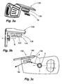
- FIGS. 3a to 3c show an alternative control deflector 130. This can in the embodiment of the Figures 1 and 2 replace the control deflector 30 provided there.
- This second embodiment of a control deflector has a surface portion 138 on its side facing the liquid jet, on which parallel to the outlet direction 4 of the liquid jet guide ribs 144 are provided which extend orthogonally from the surface portion 138.
- These six guide ribs 144 define a total of five intermediate guide channels 142, which are aligned parallel to each other.
- the guide ribs 144 are here as out Figure 3c View is formed so that they have in the direction of the exit direction 4 has a rising depth.
- the guide channels 142 each have a width of about 2 mm and an exit-side depth of also about 2 mm.
- the liquid jet which emerges in the direction of the outlet direction 4 from the corresponding opening of the watering device, inevitably has a slight expansion, which is reinforced in the course of the impact on the surface element 138.
- the guide channels 142 compensate for this expansion by each receiving a portion of the liquid jet and realign this part of the liquid with respect to its direction of movement. Accordingly, at the exit side of the guide channels 142, the liquid exits with a largely uniform direction 5a.
- a erfindungsgze ⁇ e embodiment is in the FIGS. 4a to 4d shown.
- the peculiarity of this Steuerdeflektor 230 of FIGS. 4a to 4d is that although he according to the embodiments of the FIGS. 3a to 3c a plurality of guide channels 242a, 242b, but these are not formed parallel to each other, but to run towards each other. In approximately parallel to the outlet direction 4 of the liquid jet while a Scholeitkanal 242a is aligned.
- a total of six secondary ducts 242b are provided, of which at least some run at an acute angle to the main duct 242a and open into it.
- the guide channels each have an approximately semicircular cross-section.
- the Hautleitkanal 242a has a width of about 3mm and a depth of about 1.5mm.
- the Volunteerleitkanäle 242b are formed slightly smaller.
- This herringbone-like structure means that the liquid jet, which has already been slightly widened as it emerges from the nozzle, which is further widened in the course of the impact on the surface element 238, is recombined to the desired extent.
- the exit of the liquid at the end of the guide channels 242a, 242b in the direction 5b is consequently not only largely parallel, as in the embodiment of FIGS. 3a to 3c , but also as a largely uniform liquid jet.
- FIGS. 4a to 4d Another special feature of the embodiment of the FIGS. 4a to 4d is that the guide channels 242a, 242b are not separated from each other by guide ribs, but are provided as groove-like depressions directly in the surface element 238.
- it is a turbine sprinkler.
- a reduction of the throwing distance can be achieved with other types of sprinklers, for example impulse sprinklers.
Abstract
Description
Die Erfindung betrifft eine Bewässerungsvorrichtung zur Bewässerung von Vegetation mit einer Flüssigkeit, wobei die Bewässerungsvorrichtung zum stationären Betrieb ausgebildet ist, mit einer Austrittsdüse aus der die Flüssigkeit im Betrieb in Form eines Flüssigkeitsstrahls in einer Austrittsrichtung austritt und einem Steuerungsdeflektor, wobei der Steuerungsdeflektor fluchtend in der Austrittsrichtung des Flüssigkeitsstrahls anordenbar ist und dafür ausgebildet ist, die Richtung des Flüssigkeitsstrahls zu beeinflussen.The invention relates to an irrigation device for irrigating vegetation with a liquid, wherein the irrigation device is designed for stationary operation, with an exit nozzle from which the liquid emerges in operation in the form of a liquid jet in an exit direction and a control deflector, the control deflector being aligned in the exit direction the liquid jet can be arranged and is adapted to influence the direction of the liquid jet.
Derartige Bewässerungsvorrichtungen sind aus dem Stand der Technik bekannt. Sie werden benutzt, um in Gärten Pflanzen und Rasenflächen zu bewässern. Die gattungsgemäß vorgesehenen Steuerungsdeflektoren dienen bei derartigen Bewässerungsvorrichtungen dazu, die Wurfweite zu reduzieren, so dass auch ein Nahbereich um die Bewässerungsvorrichtung herum bewässert werden kann. Bei den aus dem Stand der Technik bekannten Steuerungsdeflektoren handelt es sich um ebene Deflektorflächen, die in vorzugsweise verstellbarer Weise in den Strahlverlauf des Flüssigkeitsstrahls eingerückt werden können, um dessen Richtung oder die Richtung eines Teils der Flüssigkeit zu beeinflussen. Der Flüssigkeitsstrahl ist üblicherweise beim Austritt aus der Austrittsdüse insbesondere in vertikaler Richtung leicht aufgefächert, damit die Wurfweite nicht einheitlich ist, sondern eine ringförmige Fläche mit Flüssigkeit versorgt wird.Such irrigation devices are known from the prior art. They are used to water plants and lawns in gardens. The generically provided control deflectors are used in such irrigation devices to reduce the throw distance, so that even a short range around the irrigation device can be irrigated around. The control deflectors known from the prior art are planar deflector surfaces which can be adjusted in a preferably adjustable manner Beam path of the liquid jet can be engaged to affect its direction or the direction of a portion of the liquid. The liquid jet is usually slightly fanned out at the outlet from the outlet nozzle, in particular in the vertical direction, so that the throwing distance is not uniform, but an annular surface is supplied with liquid.
Als nachteilig an dem aus dem Stand der Technik bekannten gattungsgemäßen Bewässerungsvorrichtungen wird angesehen, dass die Steuerungsfläche zu einer unerwünschten Aufweitung des Flüssigkeitsstrahls in horizontaler Richtung führt.A disadvantage of the known from the prior art irrigation devices is considered that the control surface leads to an undesirable widening of the liquid jet in the horizontal direction.
Aus der
Ähnliches ist auch aus der
Aus der
Aus der
Die Offenlegungsschrift
Aufgabe der Erfindung ist es, eine gattungsgemäße Bewässerungsvorrichtung dahingehend weiterzubilden, dass ein verbessert gebündeltes Strahlbild jenseits des Steuerungsdeflektors erzielt wird.The object of the invention is to develop a generic irrigation device to the effect that an improved bundled jet image is achieved beyond the control deflector.
Erfindungsgemäß wird durch eine Bewässerungsvorrichtung gemäß Anspruch 1 erreicht. Bevorzugte Ausfüfrungsformen werden von den abhängigen Ansprüchen dargestellt.According to the invention is achieved by an irrigation device according to claim 1. Preferred embodiments are represented by the dependent claims.
Weitere Vorteil und Merkmale der Erfindung ergeben sich aus den Ansprüchen sowie einer nachfolgenden Beschreibung von bevorzugten Ausführungsbeispielen der Erfindung, die anhand der Zeichnungen dargestellt sind. Dabei zeigen:
- Figur 1 und 2
- eine Bewässerungsvorrichtung in zwei Ansichten,
- Fig. 3a bis 3c
- mehrere Ansichten einer zweiten Ausführungsform eines Deflektors einer Bewässe- rungsvorrichtung und
- Fig. 4a bis 4d
- mehrere Ansichten einer Ausführungsform ei- nes Deflektors einer erfindungsgemäßen Bewässe- rungsvorrichtung
- FIGS. 1 and 2
- an irrigation device in two views,
- Fig. 3a to 3c
- several views of a second embodiment of a deflector irrigation device and
- Fig. 4a to 4d
- several views of an embodiment of a deflector of Bewasser- inventive device according to the invention
Die
Ein oberer Abschnitt der Bewässerungsvorrichtung 10 ist gegenüber einem unteren Abschnitt um die Hauptachse 2 drehbar ausgebildet. Die Relativbewegung wird im Betrieb in nicht näher dargestellter Art durch die Strömung der Flüssigkeit erreicht, die durch die Bewässerungsvorrichtung 10 hindurch von Anschlussstutzen 12 zur Austragsdüse 16 geleitet wird. Der abgedeckte Winkelbereich für die Relativbewegung ist durch Einstellräder 18 einstellbar. Durch die Relativdrehung wird erreicht, dass die durch die Austrittsdüse 16 austretende Flüssigkeit im Bereich einer kreisförmigen oder kreissegmentförmigen Fläche verteilt wird.An upper portion of the
Die Austragbaugruppe 14 umfasst neben der Austragdüse 16 einen Steuerungsdeflektor 30, der an einem Gehäuseabschnitt 20 um eine horizontale Schwenkachse 6 schwenkbar angelenkt ist. Die Einstellung des Schwenkwinkels des Steuerungsdeflektors erfolgt über ein Justierrad 22 erreicht werden, welches drehbar am Gehäuseabschnitt 20 angelenkt ist. Über eine Kopplungsverzahnung 24 am Justierrad 22 und dem Steuerungsdeflektor 30 wird eine Drehbewegung des Justierrads 22 in eine Schwenkbewegung des Steuerungsdeflektors 30 überführt. Der Steuerungsdeflektor 30 kann dadurch zwischen einer oberen Schwenkstellung, in der er nicht in Austrittsrichtung 4 mit der Austrittsdüse 16 fluchtend angeordnet ist, und einer unteren Schwenkstellung, in der aus der Austrittsdüse 16 austretende Flüssigkeit in Kontakt mit dem Steuerungsdeflektor 30 gerät, bewegt werden. Bei der Stellung der
An seiner Innenfläche 40, die der Austrittsdüse 16 zugewandt ist, ist der Steuerungsdeflektor 30 als Strömungsleiteinrichtung 40, 42 ausgebildet. Zu diesem Zweck weist die Innenfläche 40 als Teil einer Strömungsleitrinne zwei V-förmig angeordnete und einen Winkel von etwa 80° einschließende Schenkelflächen 40a, 40b auf. Diese Schenkelflächen 40a, 40b sind in einem Übergangsbereich miteinander verbunden und bilden dort eine Kehlrinne 42.On its
In Betrieb wird die Bewässerungsflüssigkeit, in der Regel Wasser, gegebenenfalls mit Düngezusätzen, durch die Austrittsdüse 16 in Form eines Flüssigkeitsstrahls ausgegeben. Dieser Flüssigkeitsstrahl ist in horizontaler Richtung leicht und in vertikaler Richtung in höherem Maße aufgefächert. Wenn der Steuerungsdeflektor 30 in eine untere Schwenkstellung eingestellt ist, prallt der Flüssigkeitsstrahl im spitzen Winkel im Bereich der Kehlrinne 42 auf die Innenfläche 40 des Steuerungsdeflektors 30. Die Bewässerungsflüssigkeit wird hierdurch bezüglich ihrer Richtung umgelenkt, so dass die aus der Kehlrinne 42 austretende Flüssigkeit in einem Nahbereich um die Bewässerungsvorrichtung auf Pflanzen oder Rasen in der Umgebung auftrifft. Um gleichzeitig sowohl den Fernbereich als auch den Nahbereich mit Flüssigkeit zu versorgen, kann der Steuerungsdeflektor so eingestellt werden, dass lediglich ein oberer Teil des vertikal aufgefächerten Flüssigkeitsstrahls auf den Steuerungsdeflektor 30 aufprallt und dadurch bezüglich seiner Wurfweite vermindert wird.In operation, the irrigation fluid, usually water, optionally with fertilizer additives, through the
Die
Die Besonderheit dieser zweiten Ausführungsform eines Steuerungsdeflektors liegt darin, dass dieser einen Flächenabschnitt 138 auf seiner dem Flüssigkeitsstrahl zugewandten Seite aufweist, an dem parallel zur Austrittsrichtung 4 des Flüssigkeitsstrahls Leitrippen 144 vorgesehen sind, die sich orthogonal vom Flächenabschnitt 138 erstrecken Diese sechs Leitrippen 144 begrenzen insgesamt fünf dazwischen liegende Leitkanäle 142, die parallel zueinander ausgerichtet sind. Die Leitrippen 144 sind dabei, wie aus
Der Flüssigkeitsstrahl, der in Richtung der Austrittsrichtung 4 aus der entsprechenden Öffnung der Bewässerungsvorrichtung austritt, weist zwangsläufig eine leichte Aufweitung auf, die im Zuge des Aufpralls auf dem Flächenelement 138 noch verstärkt wird. Die Leitkanäle 142 kompensieren diese Aufweitung, indem sie jeweils einen Anteil des Flüssigkeitsstrahls aufnehmen und diesen Teil der Flüssigkeit bezüglich seiner Bewegungsrichtung neu ausrichten. An der Austrittsseite der Leitkanäle 142 tritt die Flüssigkeit demzufolge mit einer weitgehend einheitlichen Richtung 5a aus.The liquid jet, which emerges in the direction of the
Eine erfindungsgmäβe Ausführungsform ist in den
Diese fischgrätenartige Struktur führt dazu, dass der schon bei dem Austritt aus der Düse leicht aufgeweiteten Flüssigkeitsstrahl, der im Zuge des Aufpralls auf dem Flächenelement 238 weiter aufgeweitet wird, in gewünschtem Maße wieder zusammengeführt wird. Der Austritt der Flüssigkeit am Ende der Leitkanäle 242a, 242b in Richtung 5b erfolgt demzufolge nicht nur weitgehend parallel, wie bei der Ausführungsform der
Eine weitere Besonderheit der Ausführungsform der
Bei dem dargestellten Ausführungsbeispiel handelt es sich um einen Turbinenregner. In gleicher Art und Weise ist jedoch auch bei anderen Regnertypen, beispielsweise bei Impulsregnern, eine Reduzierung der Wurfweite zu erzielen.In the illustrated embodiment, it is a turbine sprinkler. In the same way, however, a reduction of the throwing distance can be achieved with other types of sprinklers, for example impulse sprinklers.
Claims (13)
- An irrigation device (10) for irrigating vegetation with a liquid, wherein the irrigation device (10) is designed for stationary operation, with- an outflow nozzle (16) out of which the liquid in operation may flow in the form of a liquid jet in an outflow direction (4) and- a control deflector (30; 130; 230) in a fixed position relatively to the outflow nozzle (16) during operation,
wherein- the control deflector (230) may be positioned in line in the outflow direction (4) of the liquid jet and is designed so as to exert influence on the direction of at least one portion of the liquid jet- with the control deflector (230) is associated a flow guiding device (142; 242a; 242b) which may act against a fanning-out of the liquid jet in a horizontal extension direction transverse to the jet direction- the flow guiding device (242a; 242b) comprises a functional surface (238) for exerting influence on the jet direction- several guiding channels (242a; 242b) are provided on the functional surface (238), which are positioned or may be positioned so that the liquid jet flowing out of the outflow nozzle (16) may enter the guiding channels (242a; 242b) and wherein the guiding channels (242a; 242b) are formed by guiding grooves (242a; 242b) in the functional surface (238)characterized in that the guiding channels (242b) in the direction of the outflow of the liquid are oriented so as to extend towards each other,
or in that the edge of the functional surface (238) located in the area of the ends of the guiding channels (242a; 242b) is V-shaped, so that the functional surface increasingly extends further along the outflow direction of the liquid from its middle area extending in the outflow direction of the liquid as far as its edge. - The irrigation device (10) according to claim 1, characterized in that the guiding channels (242a; 242b)• have an average depth of at least 2 mm, preferably of at least 4 mm and/or• a width of less than 5 mm, preferably less than 3 mm.
- The irrigation device (10) according to one of claims 1 or 2, characterized in that a guiding channel (242a) is oriented as a main guiding channel approximately parallel to the outflow direction (4) of the liquid jet.
- The irrigation device (10) according to one of the preceding claims, characterized in that the outflow nozzle (16) is oriented in such a way that in the outflow direction (4) of the liquid jet outflowing therefrom, a radial component relatively to a vertical main axis (2) of the irrigation device is thereby determined.
- The irrigation device (10) according to one of the preceding claims, characterized in that the outflow nozzle (16) and the control deflector (230) are formed together in a fixed position relatively to each other so as to be rotatable around a vertical main axis (2) of the irrigation device (10).
- The irrigation device (10) according to one of the preceding claims, characterized in that the control deflector (230) is formed so as to be able to swivel around a horizontal axis (6), and preferably be blocked in free swivelling positions or in defined swivel locking positions.
- The irrigation device (10) according to one of the preceding claims, characterized in that the functional surface (238) is provided in a single piece on the control deflector (230).
- The irrigation device according to one of the preceding claims, characterized in that the functional surface (238) is formed uneven.
- The irrigation device (10) according to one of the preceding claims, characterized in that the functional surface is formed concave.
- The irrigation device (10) according to one of the preceding claims, characterized in that the flow guiding device (242a; 242b) is formed in such a way that the jet direction is only influenced relatively to a vertical direction component.
- The irrigation device (10) according to one of the preceding claims, characterized in that the flow guiding device (242a; 242b) has a flow guiding groove (242a, 242b) extending in a main extension direction, the main extension direction of which preferably spans a vertical plane with the outflow direction of the liquid jet.
- The irrigation device (10) according to one of the preceding claims, characterized in that the flow guiding groove comprises two side surfaces folded towards each other, and connected to each other in a transition area, wherein the angle between the side surfaces is comprised between 10° and 170°, preferably between 70° and 110°, in particular 90°.
- The irrigation device (10) according to one of the preceding claims, characterized in that the flow guiding groove (242a, 242b) has an average inner radius of less than 6 mm, preferably less than 4 mm, in particular less than 1 mm.
Priority Applications (1)
| Application Number | Priority Date | Filing Date | Title |
|---|---|---|---|
| PL10000556T PL2181772T3 (en) | 2007-03-07 | 2008-03-06 | Irrigation device |
Applications Claiming Priority (2)
| Application Number | Priority Date | Filing Date | Title |
|---|---|---|---|
| DE102007012273A DE102007012273A1 (en) | 2007-03-07 | 2007-03-07 | watering device |
| EP08004136A EP1967279B1 (en) | 2007-03-07 | 2008-03-06 | Irrigation device |
Related Parent Applications (2)
| Application Number | Title | Priority Date | Filing Date |
|---|---|---|---|
| EP08004136.1 Division | 2008-03-06 | ||
| EP08004136 Previously-Filed-Application | 2008-03-06 |
Publications (2)
| Publication Number | Publication Date |
|---|---|
| EP2181772A1 EP2181772A1 (en) | 2010-05-05 |
| EP2181772B1 true EP2181772B1 (en) | 2012-05-09 |
Family
ID=39338653
Family Applications (2)
| Application Number | Title | Priority Date | Filing Date |
|---|---|---|---|
| EP10000556A Active EP2181772B1 (en) | 2007-03-07 | 2008-03-06 | Irrigation device |
| EP08004136A Active EP1967279B1 (en) | 2007-03-07 | 2008-03-06 | Irrigation device |
Family Applications After (1)
| Application Number | Title | Priority Date | Filing Date |
|---|---|---|---|
| EP08004136A Active EP1967279B1 (en) | 2007-03-07 | 2008-03-06 | Irrigation device |
Country Status (4)
| Country | Link |
|---|---|
| EP (2) | EP2181772B1 (en) |
| AT (2) | ATE556780T1 (en) |
| DE (2) | DE102007012273A1 (en) |
| PL (2) | PL1967279T3 (en) |
Families Citing this family (2)
| Publication number | Priority date | Publication date | Assignee | Title |
|---|---|---|---|---|
| EP2651566B1 (en) * | 2010-12-16 | 2016-10-12 | Husquarna AB | Deflector for a sprinkler |
| WO2019215716A1 (en) * | 2018-05-09 | 2019-11-14 | Metzerplas Cooperative Agricultural Organization Ltd. | Rotating sprinkler |
Family Cites Families (10)
| Publication number | Priority date | Publication date | Assignee | Title |
|---|---|---|---|---|
| DE490515C (en) | 1930-01-29 | Georg Bode | Irrigation turbine with gutter-like blades | |
| CH80782A (en) | 1918-07-31 | 1919-09-16 | Georg Chiogna | Lawn sprinkler |
| US1778994A (en) * | 1929-11-06 | 1930-10-21 | Joseph H Allen | Lawn-spray-control device |
| US1840721A (en) * | 1930-04-03 | 1932-01-12 | James W Ingram | Rotatable sprinkler |
| DE889236C (en) * | 1951-08-24 | 1953-09-10 | Karl Ludwig Lanninger | Gearless wide-range sprinkler |
| US3391868A (en) * | 1966-02-17 | 1968-07-09 | Ralph D. Cooney | Rotary sprinkler with variable range |
| FR2346968A1 (en) * | 1976-04-07 | 1977-11-04 | Mangon Michel | Variable range liq. atomising spray - comprises nozzle moved back and forth in variable sector and driven by water pressure |
| US4984740A (en) * | 1989-06-19 | 1991-01-15 | Hodge Robert B | Water sprinkler with variable stream-distance adjustment |
| IL121726A (en) * | 1997-09-09 | 2001-09-13 | Mamtirim Dan | Strip pattern irrigating sprinkler |
| US7234652B2 (en) | 2005-03-30 | 2007-06-26 | Robert Rodeman | Double curved surface deflector system for rotary sprinklers |
-
2007
- 2007-03-07 DE DE102007012273A patent/DE102007012273A1/en not_active Withdrawn
-
2008
- 2008-03-06 PL PL08004136T patent/PL1967279T3/en unknown
- 2008-03-06 PL PL10000556T patent/PL2181772T3/en unknown
- 2008-03-06 AT AT10000556T patent/ATE556780T1/en active
- 2008-03-06 EP EP10000556A patent/EP2181772B1/en active Active
- 2008-03-06 DE DE502008001459T patent/DE502008001459D1/en active Active
- 2008-03-06 EP EP08004136A patent/EP1967279B1/en active Active
- 2008-03-06 AT AT08004136T patent/ATE483529T1/en active
Also Published As
| Publication number | Publication date |
|---|---|
| EP1967279B1 (en) | 2010-10-06 |
| PL2181772T3 (en) | 2012-11-30 |
| EP1967279A1 (en) | 2008-09-10 |
| DE502008001459D1 (en) | 2010-11-18 |
| PL1967279T3 (en) | 2011-03-31 |
| ATE483529T1 (en) | 2010-10-15 |
| DE102007012273A1 (en) | 2008-09-11 |
| EP2181772A1 (en) | 2010-05-05 |
| ATE556780T1 (en) | 2012-05-15 |
Similar Documents
| Publication | Publication Date | Title |
|---|---|---|
| EP0826426B1 (en) | Sprinkler | |
| DE102011000344B4 (en) | Arrangement for adjusting the nozzles of a sprinkler | |
| DE2819945C2 (en) | Device for spraying liquid | |
| DE60320687T2 (en) | Ventilation nozzle for ventilation systems | |
| DE102005010550B4 (en) | Sanitary water outlet | |
| EP0301367A2 (en) | Sprinkling device | |
| EP0970752B1 (en) | sprinkling device | |
| DE1400729A1 (en) | Spray device for liquids | |
| EP0970753B1 (en) | Method for adjusting the pattern of a sprinkler device and sprinkler device | |
| DE2736314C3 (en) | Nozzle for spraying a pressurized medium | |
| DE2906023C3 (en) | Hammer sprinkler | |
| EP2181772B1 (en) | Irrigation device | |
| EP1853770B1 (en) | Sanitary water-outlet fitting with jet regulator for deflecting the exiting water jet | |
| EP1502653B1 (en) | Nozzle for spraying a surface | |
| EP1469947B1 (en) | Sprinkler arrangement | |
| DE2542559A1 (en) | Spray distributor head for fouids - has flow surfaces and distributor surface with angular adjustment system | |
| DE102004001222B4 (en) | Nozzle unit for cooking appliance has openings perpendicular to and parallel to axis of symmetry and each connected to chamber into which pipe opens eccentrically | |
| AT525866A2 (en) | CENTER PIVOT END NOZZLE AND SPRINKLER | |
| DE1559665C3 (en) | ||
| DE2834243C2 (en) | Air outlet nozzle for electrically operated hair dryers | |
| DE3924794C2 (en) | Spray nozzle, especially for irrigation sprinklers | |
| DE202007014407U1 (en) | Spray nozzle with the possibility of spraying water on all sides | |
| DE3622603C2 (en) | ||
| DE202004014604U1 (en) | Sprinkler with movable jets for sprinkling water has tubular body and long strip connected to bellows | |
| DE8304829U1 (en) | SPRINKLE NOZZLE |
Legal Events
| Date | Code | Title | Description |
|---|---|---|---|
| PUAI | Public reference made under article 153(3) epc to a published international application that has entered the european phase |
Free format text: ORIGINAL CODE: 0009012 |
|
| AC | Divisional application: reference to earlier application |
Ref document number: 1967279 Country of ref document: EP Kind code of ref document: P |
|
| AK | Designated contracting states |
Kind code of ref document: A1 Designated state(s): AT BE BG CH CY CZ DE DK EE ES FI FR GB GR HR HU IE IS IT LI LT LU LV MC MT NL NO PL PT RO SE SI SK TR |
|
| AX | Request for extension of the european patent |
Extension state: AL BA MK RS |
|
| RIN1 | Information on inventor provided before grant (corrected) |
Inventor name: BISCHLER, EUGEN Inventor name: RENNER, THOMAS Inventor name: SCHIEDT, CHRISTOPH Inventor name: FREY, REINER |
|
| 17P | Request for examination filed |
Effective date: 20101105 |
|
| RIC1 | Information provided on ipc code assigned before grant |
Ipc: B05B 3/02 20060101AFI20111013BHEP Ipc: B05B 3/04 20060101ALN20111013BHEP Ipc: B05B 1/26 20060101ALI20111013BHEP |
|
| GRAP | Despatch of communication of intention to grant a patent |
Free format text: ORIGINAL CODE: EPIDOSNIGR1 |
|
| RIC1 | Information provided on ipc code assigned before grant |
Ipc: B05B 1/26 20060101ALI20111021BHEP Ipc: B05B 3/02 20060101AFI20111021BHEP Ipc: B05B 3/04 20060101ALN20111021BHEP |
|
| GRAS | Grant fee paid |
Free format text: ORIGINAL CODE: EPIDOSNIGR3 |
|
| GRAA | (expected) grant |
Free format text: ORIGINAL CODE: 0009210 |
|
| AC | Divisional application: reference to earlier application |
Ref document number: 1967279 Country of ref document: EP Kind code of ref document: P |
|
| AK | Designated contracting states |
Kind code of ref document: B1 Designated state(s): AT BE BG CH CY CZ DE DK EE ES FI FR GB GR HR HU IE IS IT LI LT LU LV MC MT NL NO PL PT RO SE SI SK TR |
|
| REG | Reference to a national code |
Ref country code: GB Ref legal event code: FG4D Free format text: NOT ENGLISH |
|
| REG | Reference to a national code |
Ref country code: AT Ref legal event code: REF Ref document number: 556780 Country of ref document: AT Kind code of ref document: T Effective date: 20120515 Ref country code: CH Ref legal event code: EP |
|
| REG | Reference to a national code |
Ref country code: IE Ref legal event code: FG4D Free format text: LANGUAGE OF EP DOCUMENT: GERMAN |
|
| REG | Reference to a national code |
Ref country code: DE Ref legal event code: R096 Ref document number: 502008007165 Country of ref document: DE Effective date: 20120705 |
|
| REG | Reference to a national code |
Ref country code: NL Ref legal event code: VDEP Effective date: 20120509 |
|
| REG | Reference to a national code |
Ref country code: LT Ref legal event code: MG4D Effective date: 20120523 |
|
| PG25 | Lapsed in a contracting state [announced via postgrant information from national office to epo] |
Ref country code: FI Free format text: LAPSE BECAUSE OF FAILURE TO SUBMIT A TRANSLATION OF THE DESCRIPTION OR TO PAY THE FEE WITHIN THE PRESCRIBED TIME-LIMIT Effective date: 20120509 Ref country code: CY Free format text: LAPSE BECAUSE OF FAILURE TO SUBMIT A TRANSLATION OF THE DESCRIPTION OR TO PAY THE FEE WITHIN THE PRESCRIBED TIME-LIMIT Effective date: 20120509 Ref country code: NO Free format text: LAPSE BECAUSE OF FAILURE TO SUBMIT A TRANSLATION OF THE DESCRIPTION OR TO PAY THE FEE WITHIN THE PRESCRIBED TIME-LIMIT Effective date: 20120809 Ref country code: LT Free format text: LAPSE BECAUSE OF FAILURE TO SUBMIT A TRANSLATION OF THE DESCRIPTION OR TO PAY THE FEE WITHIN THE PRESCRIBED TIME-LIMIT Effective date: 20120509 Ref country code: IS Free format text: LAPSE BECAUSE OF FAILURE TO SUBMIT A TRANSLATION OF THE DESCRIPTION OR TO PAY THE FEE WITHIN THE PRESCRIBED TIME-LIMIT Effective date: 20120909 Ref country code: SE Free format text: LAPSE BECAUSE OF FAILURE TO SUBMIT A TRANSLATION OF THE DESCRIPTION OR TO PAY THE FEE WITHIN THE PRESCRIBED TIME-LIMIT Effective date: 20120509 |
|
| PG25 | Lapsed in a contracting state [announced via postgrant information from national office to epo] |
Ref country code: HR Free format text: LAPSE BECAUSE OF FAILURE TO SUBMIT A TRANSLATION OF THE DESCRIPTION OR TO PAY THE FEE WITHIN THE PRESCRIBED TIME-LIMIT Effective date: 20120509 Ref country code: LV Free format text: LAPSE BECAUSE OF FAILURE TO SUBMIT A TRANSLATION OF THE DESCRIPTION OR TO PAY THE FEE WITHIN THE PRESCRIBED TIME-LIMIT Effective date: 20120509 Ref country code: SI Free format text: LAPSE BECAUSE OF FAILURE TO SUBMIT A TRANSLATION OF THE DESCRIPTION OR TO PAY THE FEE WITHIN THE PRESCRIBED TIME-LIMIT Effective date: 20120509 Ref country code: GR Free format text: LAPSE BECAUSE OF FAILURE TO SUBMIT A TRANSLATION OF THE DESCRIPTION OR TO PAY THE FEE WITHIN THE PRESCRIBED TIME-LIMIT Effective date: 20120810 Ref country code: PT Free format text: LAPSE BECAUSE OF FAILURE TO SUBMIT A TRANSLATION OF THE DESCRIPTION OR TO PAY THE FEE WITHIN THE PRESCRIBED TIME-LIMIT Effective date: 20120910 |
|
| REG | Reference to a national code |
Ref country code: PL Ref legal event code: T3 |
|
| PG25 | Lapsed in a contracting state [announced via postgrant information from national office to epo] |
Ref country code: CZ Free format text: LAPSE BECAUSE OF FAILURE TO SUBMIT A TRANSLATION OF THE DESCRIPTION OR TO PAY THE FEE WITHIN THE PRESCRIBED TIME-LIMIT Effective date: 20120509 Ref country code: SK Free format text: LAPSE BECAUSE OF FAILURE TO SUBMIT A TRANSLATION OF THE DESCRIPTION OR TO PAY THE FEE WITHIN THE PRESCRIBED TIME-LIMIT Effective date: 20120509 Ref country code: NL Free format text: LAPSE BECAUSE OF FAILURE TO SUBMIT A TRANSLATION OF THE DESCRIPTION OR TO PAY THE FEE WITHIN THE PRESCRIBED TIME-LIMIT Effective date: 20120509 Ref country code: RO Free format text: LAPSE BECAUSE OF FAILURE TO SUBMIT A TRANSLATION OF THE DESCRIPTION OR TO PAY THE FEE WITHIN THE PRESCRIBED TIME-LIMIT Effective date: 20120509 Ref country code: EE Free format text: LAPSE BECAUSE OF FAILURE TO SUBMIT A TRANSLATION OF THE DESCRIPTION OR TO PAY THE FEE WITHIN THE PRESCRIBED TIME-LIMIT Effective date: 20120509 Ref country code: DK Free format text: LAPSE BECAUSE OF FAILURE TO SUBMIT A TRANSLATION OF THE DESCRIPTION OR TO PAY THE FEE WITHIN THE PRESCRIBED TIME-LIMIT Effective date: 20120509 |
|
| PG25 | Lapsed in a contracting state [announced via postgrant information from national office to epo] |
Ref country code: IT Free format text: LAPSE BECAUSE OF FAILURE TO SUBMIT A TRANSLATION OF THE DESCRIPTION OR TO PAY THE FEE WITHIN THE PRESCRIBED TIME-LIMIT Effective date: 20120509 |
|
| PLBE | No opposition filed within time limit |
Free format text: ORIGINAL CODE: 0009261 |
|
| STAA | Information on the status of an ep patent application or granted ep patent |
Free format text: STATUS: NO OPPOSITION FILED WITHIN TIME LIMIT |
|
| 26N | No opposition filed |
Effective date: 20130212 |
|
| PG25 | Lapsed in a contracting state [announced via postgrant information from national office to epo] |
Ref country code: ES Free format text: LAPSE BECAUSE OF FAILURE TO SUBMIT A TRANSLATION OF THE DESCRIPTION OR TO PAY THE FEE WITHIN THE PRESCRIBED TIME-LIMIT Effective date: 20120820 |
|
| PGRI | Patent reinstated in contracting state [announced from national office to epo] |
Ref country code: IT Effective date: 20130401 |
|
| REG | Reference to a national code |
Ref country code: DE Ref legal event code: R097 Ref document number: 502008007165 Country of ref document: DE Effective date: 20130212 |
|
| PG25 | Lapsed in a contracting state [announced via postgrant information from national office to epo] |
Ref country code: BG Free format text: LAPSE BECAUSE OF FAILURE TO SUBMIT A TRANSLATION OF THE DESCRIPTION OR TO PAY THE FEE WITHIN THE PRESCRIBED TIME-LIMIT Effective date: 20120809 |
|
| BERE | Be: lapsed |
Owner name: GARDENA MANUFACTURING G.M.B.H. Effective date: 20130331 |
|
| PG25 | Lapsed in a contracting state [announced via postgrant information from national office to epo] |
Ref country code: MC Free format text: LAPSE BECAUSE OF NON-PAYMENT OF DUE FEES Effective date: 20130331 |
|
| REG | Reference to a national code |
Ref country code: CH Ref legal event code: PL |
|
| REG | Reference to a national code |
Ref country code: IE Ref legal event code: MM4A |
|
| PG25 | Lapsed in a contracting state [announced via postgrant information from national office to epo] |
Ref country code: LI Free format text: LAPSE BECAUSE OF NON-PAYMENT OF DUE FEES Effective date: 20130331 Ref country code: CH Free format text: LAPSE BECAUSE OF NON-PAYMENT OF DUE FEES Effective date: 20130331 Ref country code: BE Free format text: LAPSE BECAUSE OF NON-PAYMENT OF DUE FEES Effective date: 20130331 Ref country code: IE Free format text: LAPSE BECAUSE OF NON-PAYMENT OF DUE FEES Effective date: 20130306 |
|
| REG | Reference to a national code |
Ref country code: GB Ref legal event code: 732E Free format text: REGISTERED BETWEEN 20140403 AND 20140409 |
|
| REG | Reference to a national code |
Ref country code: FR Ref legal event code: TP Owner name: HUSQVARNA AB, SE Effective date: 20140407 |
|
| REG | Reference to a national code |
Ref country code: AT Ref legal event code: MM01 Ref document number: 556780 Country of ref document: AT Kind code of ref document: T Effective date: 20130306 |
|
| PG25 | Lapsed in a contracting state [announced via postgrant information from national office to epo] |
Ref country code: MT Free format text: LAPSE BECAUSE OF FAILURE TO SUBMIT A TRANSLATION OF THE DESCRIPTION OR TO PAY THE FEE WITHIN THE PRESCRIBED TIME-LIMIT Effective date: 20120509 |
|
| REG | Reference to a national code |
Ref country code: DE Ref legal event code: R081 Ref document number: 502008007165 Country of ref document: DE Owner name: HUSQVARNA AB, SE Free format text: FORMER OWNER: GARDENA MANUFACTURING GMBH, 89079 ULM, DE Effective date: 20140627 |
|
| PG25 | Lapsed in a contracting state [announced via postgrant information from national office to epo] |
Ref country code: AT Free format text: LAPSE BECAUSE OF NON-PAYMENT OF DUE FEES Effective date: 20130306 |
|
| PG25 | Lapsed in a contracting state [announced via postgrant information from national office to epo] |
Ref country code: TR Free format text: LAPSE BECAUSE OF FAILURE TO SUBMIT A TRANSLATION OF THE DESCRIPTION OR TO PAY THE FEE WITHIN THE PRESCRIBED TIME-LIMIT Effective date: 20120509 |
|
| PG25 | Lapsed in a contracting state [announced via postgrant information from national office to epo] |
Ref country code: HU Free format text: LAPSE BECAUSE OF FAILURE TO SUBMIT A TRANSLATION OF THE DESCRIPTION OR TO PAY THE FEE WITHIN THE PRESCRIBED TIME-LIMIT; INVALID AB INITIO Effective date: 20080306 Ref country code: LU Free format text: LAPSE BECAUSE OF NON-PAYMENT OF DUE FEES Effective date: 20130306 |
|
| REG | Reference to a national code |
Ref country code: FR Ref legal event code: PLFP Year of fee payment: 9 |
|
| REG | Reference to a national code |
Ref country code: FR Ref legal event code: PLFP Year of fee payment: 10 |
|
| REG | Reference to a national code |
Ref country code: FR Ref legal event code: PLFP Year of fee payment: 11 |
|
| PGFP | Annual fee paid to national office [announced via postgrant information from national office to epo] |
Ref country code: IT Payment date: 20220121 Year of fee payment: 15 |
|
| PGFP | Annual fee paid to national office [announced via postgrant information from national office to epo] |
Ref country code: FR Payment date: 20230217 Year of fee payment: 16 |
|
| PGFP | Annual fee paid to national office [announced via postgrant information from national office to epo] |
Ref country code: PL Payment date: 20230111 Year of fee payment: 16 Ref country code: GB Payment date: 20230213 Year of fee payment: 16 Ref country code: DE Payment date: 20230206 Year of fee payment: 16 |
|
| P01 | Opt-out of the competence of the unified patent court (upc) registered |
Effective date: 20230419 |