EP2180917B1 - System zur leistungssteuerung auf der basis von impedanzerkennung, wie etwa leistungssteuerung bei gewebebehandlungsgeräten - Google Patents
System zur leistungssteuerung auf der basis von impedanzerkennung, wie etwa leistungssteuerung bei gewebebehandlungsgeräten Download PDFInfo
- Publication number
- EP2180917B1 EP2180917B1 EP08796555.4A EP08796555A EP2180917B1 EP 2180917 B1 EP2180917 B1 EP 2180917B1 EP 08796555 A EP08796555 A EP 08796555A EP 2180917 B1 EP2180917 B1 EP 2180917B1
- Authority
- EP
- European Patent Office
- Prior art keywords
- impedance
- energy
- energy delivery
- temperature
- power
- Prior art date
- Legal status (The legal status is an assumption and is not a legal conclusion. Google has not performed a legal analysis and makes no representation as to the accuracy of the status listed.)
- Active
Links
Images


Classifications
-
- A—HUMAN NECESSITIES
- A61—MEDICAL OR VETERINARY SCIENCE; HYGIENE
- A61B—DIAGNOSIS; SURGERY; IDENTIFICATION
- A61B18/00—Surgical instruments, devices or methods for transferring non-mechanical forms of energy to or from the body
- A61B18/04—Surgical instruments, devices or methods for transferring non-mechanical forms of energy to or from the body by heating
- A61B18/12—Surgical instruments, devices or methods for transferring non-mechanical forms of energy to or from the body by heating by passing a current through the tissue to be heated, e.g. high-frequency current
- A61B18/1206—Generators therefor
- A61B18/1233—Generators therefor with circuits for assuring patient safety
-
- A—HUMAN NECESSITIES
- A61—MEDICAL OR VETERINARY SCIENCE; HYGIENE
- A61B—DIAGNOSIS; SURGERY; IDENTIFICATION
- A61B18/00—Surgical instruments, devices or methods for transferring non-mechanical forms of energy to or from the body
- A61B18/04—Surgical instruments, devices or methods for transferring non-mechanical forms of energy to or from the body by heating
- A61B18/12—Surgical instruments, devices or methods for transferring non-mechanical forms of energy to or from the body by heating by passing a current through the tissue to be heated, e.g. high-frequency current
- A61B18/14—Probes or electrodes therefor
- A61B18/1492—Probes or electrodes therefor having a flexible, catheter-like structure, e.g. for heart ablation
-
- A—HUMAN NECESSITIES
- A61—MEDICAL OR VETERINARY SCIENCE; HYGIENE
- A61N—ELECTROTHERAPY; MAGNETOTHERAPY; RADIATION THERAPY; ULTRASOUND THERAPY
- A61N1/00—Electrotherapy; Circuits therefor
- A61N1/18—Applying electric currents by contact electrodes
- A61N1/32—Applying electric currents by contact electrodes alternating or intermittent currents
- A61N1/36—Applying electric currents by contact electrodes alternating or intermittent currents for stimulation
- A61N1/3605—Implantable neurostimulators for stimulating central or peripheral nerve system
- A61N1/36128—Control systems
-
- A—HUMAN NECESSITIES
- A61—MEDICAL OR VETERINARY SCIENCE; HYGIENE
- A61B—DIAGNOSIS; SURGERY; IDENTIFICATION
- A61B18/00—Surgical instruments, devices or methods for transferring non-mechanical forms of energy to or from the body
- A61B2018/00053—Mechanical features of the instrument of device
- A61B2018/00214—Expandable means emitting energy, e.g. by elements carried thereon
- A61B2018/00267—Expandable means emitting energy, e.g. by elements carried thereon having a basket shaped structure
-
- A—HUMAN NECESSITIES
- A61—MEDICAL OR VETERINARY SCIENCE; HYGIENE
- A61B—DIAGNOSIS; SURGERY; IDENTIFICATION
- A61B18/00—Surgical instruments, devices or methods for transferring non-mechanical forms of energy to or from the body
- A61B2018/00315—Surgical instruments, devices or methods for transferring non-mechanical forms of energy to or from the body for treatment of particular body parts
- A61B2018/00541—Lung or bronchi
-
- A—HUMAN NECESSITIES
- A61—MEDICAL OR VETERINARY SCIENCE; HYGIENE
- A61B—DIAGNOSIS; SURGERY; IDENTIFICATION
- A61B18/00—Surgical instruments, devices or methods for transferring non-mechanical forms of energy to or from the body
- A61B2018/00571—Surgical instruments, devices or methods for transferring non-mechanical forms of energy to or from the body for achieving a particular surgical effect
- A61B2018/00577—Ablation
-
- A—HUMAN NECESSITIES
- A61—MEDICAL OR VETERINARY SCIENCE; HYGIENE
- A61B—DIAGNOSIS; SURGERY; IDENTIFICATION
- A61B18/00—Surgical instruments, devices or methods for transferring non-mechanical forms of energy to or from the body
- A61B2018/00571—Surgical instruments, devices or methods for transferring non-mechanical forms of energy to or from the body for achieving a particular surgical effect
- A61B2018/00595—Cauterization
-
- A—HUMAN NECESSITIES
- A61—MEDICAL OR VETERINARY SCIENCE; HYGIENE
- A61B—DIAGNOSIS; SURGERY; IDENTIFICATION
- A61B18/00—Surgical instruments, devices or methods for transferring non-mechanical forms of energy to or from the body
- A61B2018/00636—Sensing and controlling the application of energy
- A61B2018/00642—Sensing and controlling the application of energy with feedback, i.e. closed loop control
-
- A—HUMAN NECESSITIES
- A61—MEDICAL OR VETERINARY SCIENCE; HYGIENE
- A61B—DIAGNOSIS; SURGERY; IDENTIFICATION
- A61B18/00—Surgical instruments, devices or methods for transferring non-mechanical forms of energy to or from the body
- A61B2018/00636—Sensing and controlling the application of energy
- A61B2018/00696—Controlled or regulated parameters
- A61B2018/00702—Power or energy
-
- A—HUMAN NECESSITIES
- A61—MEDICAL OR VETERINARY SCIENCE; HYGIENE
- A61B—DIAGNOSIS; SURGERY; IDENTIFICATION
- A61B18/00—Surgical instruments, devices or methods for transferring non-mechanical forms of energy to or from the body
- A61B2018/00636—Sensing and controlling the application of energy
- A61B2018/00773—Sensed parameters
- A61B2018/00791—Temperature
-
- A—HUMAN NECESSITIES
- A61—MEDICAL OR VETERINARY SCIENCE; HYGIENE
- A61B—DIAGNOSIS; SURGERY; IDENTIFICATION
- A61B18/00—Surgical instruments, devices or methods for transferring non-mechanical forms of energy to or from the body
- A61B2018/00636—Sensing and controlling the application of energy
- A61B2018/00773—Sensed parameters
- A61B2018/00875—Resistance or impedance
-
- A—HUMAN NECESSITIES
- A61—MEDICAL OR VETERINARY SCIENCE; HYGIENE
- A61B—DIAGNOSIS; SURGERY; IDENTIFICATION
- A61B18/00—Surgical instruments, devices or methods for transferring non-mechanical forms of energy to or from the body
- A61B2018/00636—Sensing and controlling the application of energy
- A61B2018/00898—Alarms or notifications created in response to an abnormal condition
-
- A—HUMAN NECESSITIES
- A61—MEDICAL OR VETERINARY SCIENCE; HYGIENE
- A61N—ELECTROTHERAPY; MAGNETOTHERAPY; RADIATION THERAPY; ULTRASOUND THERAPY
- A61N1/00—Electrotherapy; Circuits therefor
- A61N1/18—Applying electric currents by contact electrodes
- A61N1/32—Applying electric currents by contact electrodes alternating or intermittent currents
- A61N1/36—Applying electric currents by contact electrodes alternating or intermittent currents for stimulation
- A61N1/3605—Implantable neurostimulators for stimulating central or peripheral nerve system
- A61N1/36128—Control systems
- A61N1/36146—Control systems specified by the stimulation parameters
Definitions
- the present application relates generally to medical treatment devices, such as devices that treat lung diseases by applying energy to airways to reduce the resistance to airflow in the airways.
- Asthma is a disease that makes it difficult to breathe and in many cases can be debilitating. Asthma is generally manifested by (i) bronchoconstriction, (ii) excessive mucus production, and/or (iii) inflammation and swelling of airways that cause widespread but variable airflow obstructions. Asthma can be a chronic disorder often characterized by persistent airway inflammation, but asthma can be further characterized by acute episodes of additional airway narrowing via contraction of hyper-responsive airway smooth muscle tissue.
- Conventional pharmacological approaches for managing asthma include: (i) administering anti-inflammatories and long-acting bronchodilators for long-term control, and/or (ii) administering short-acting bronchodilators for management of acute episodes. Both of these pharmacological approaches generally require repeated use of the prescribed drugs at regular intervals throughout long periods of time. However, high doses of corticosteroid antiinflammatory drugs can have serious side effects that require careful management, and some patients are resistant to steroid treatment even at high doses. As such, effective patient compliance with pharmacologic management and avoiding stimuli that triggers asthma are common barriers to successfully managing asthma.
- Asthmatx, Inc. has developed new asthma treatments that involve applying energy to alter properties of the smooth muscle tissue or other tissue (e.g., nerves, mucus glands, epithelium, blood vessels, etc.) of airways in a lung of a patient.
- smooth muscle tissue or other tissue e.g., nerves, mucus glands, epithelium, blood vessels, etc.
- Several embodiments of methods and apparatus related to such treatments are disclosed in commonly-assigned U.S. patent Nos. 6,411,852 , 6,634,363 , 7,027,869 , and 7,104,987 ; and U.S. Published Application Nos. US2005/0010270 and US2006/0247746 .
- FIG. 1 illustrates a bronchial tree 90 in which the various bronchioles 92 decrease in size and have many branches 96 as they extend from the right and left bronchi 94. Accordingly, the treatment devices should be configured to treat airways of varying sizes as well as function properly when repeatedly deployed after navigating through the tortuous anatomy.
- the energy delivery devices for delivering radio frequency (RF) energy to tissue in the lung airways have been controlled by measuring the temperature of one of the electrodes during energy delivery.
- Other types of treatment devices that deliver RF energy for other applications outside of the lung airways such as ablation and cauterization devices, have controlled the delivery of energy to cardiac and vasculature tissue based on measuring factors other than temperature.
- WO94/24949 discloses an impedance electro-surgical system with electro-surgical tools to maintain a preselected control range of tissue impedance within tissue in contact with the tool.
- Ablation and cauterization devices e.g.
- US 6,423,057 B1 have monitored impedance during a procedure and terminated energy deliver when a sharp increase in the impedance is measured. This sharp increase may correlate with a desired end result, such as tissue desiccation or protein denaturation. As such, existing ablation and cauterization systems may terminate energy delivery based on a direct relationship between an increase in impedance and an increase in temperature.
- the invention is defined in claim 1. Further aspects and preferred embodiments are defined in the dependent claims.
- the system controls power to the energy delivery device based on the measured impedance.
- the system may determine a desired or set impedance level related to parameters of the treatment site and/or of the energy delivery device, measure a current or present impedance level during or prior to energy delivery to the treatment site, and control the power to maintain the temperature or other parameter of the treatment site based on the two impedances.
- the system provides closed loop power control of energy delivery devices based on impedance feedback.
- impedance feedback By monitoring impedance at low non-ablative temperatures (e.g., temperatures below tissue desiccation or protein denaturation temperatures), several embodiments of the system may enable the simplification of devices used in the treatment systems and/or may result in more stable or consistent treatment delivery.
- This inverse correlation of temperature and impedance enables the system to (a) measure the impedance of the system using electrodes of an energy delivery device that provide energy to target tissue in order to receive feedback about the temperature or other parameters of the target tissue, and (b) adjust power to the energy delivery device accordingly.
- measuring impedance may eliminate the need to measure temperature during the delivery of radio frequency or other energy to tissue, and thus several embodiments of the system may utilize catheters without thermocouples or other temperature measurement components. As a result, several embodiments of treatment devices may be small, simple, and relatively less expensive to manufacture. Additionally, controlling power by measuring impedance may enable the system to more accurately or holistically assess the state of the tissue around the passageway because measuring impedance may result in less temperature variability in the tissue versus measuring temperature at only a single location in the passageway. This may result in a more accurate treatment and/or in more consistent energy delivery between applications because impedance monitoring may be less susceptible to variation than temperature monitoring within a treatment location or between treatment locations.
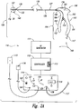
- FIG. 2A is a schematic view illustrating a system 100 for delivering energy to passageways in a patient having a power/control unit 110 and an energy delivery device 120 in accordance with an embodiment of the disclosure.
- the power/control unit 110 can include an energy generator 111 (e.g., power supply), a controller 112 having a processor 113, and a user interface 114.
- the energy generator 111 and controller 112 can provide RF energy to the energy delivery device 120, but in other embodiments the energy generator 111 and controller 112 can provide other energy modalities.
- the controller 112 can contain safety algorithms and other control algorithms that control (i) the power output to the energy delivery device 120 and (ii) the indicators 118, 119, 121, 122 of the user interface 114.
- the power/control unit 110 can further include one or more connections 123, 124, 125 for an optional return electrode 115 for monopolar RF configurations, an optional switch 116 (e.g., an actuation pedal) for directing the controller 112 to cause the energy generator 111 to provide energy, and a conductive line 117 and connector 126 coupled to the energy delivery device 120.
- an optional switch 116 e.g., an actuation pedal
- a conductive line 117 and connector 126 coupled to the energy delivery device 120.
- the energy delivery device 120 is an example of a treatment device for treating asthma or other indications associated with passageways in a human.
- the embodiment of the energy delivery device 120 illustrated in Figure 2A includes an elongated body 130 with a distal portion 132 and a proximal portion 134, an energy delivery unit 140 at the distal portion 132, and a handle 150 at the proximal portion 134.
- the length of the elongated body 130 should be sufficient to access the target tissue in airways of the lung or other passageways targeted for treatment.
- the length of the elongated body 130 can be from approximately 0.5-8 feet to allow passage through a bronchoscope and reach targeted airways deep within the lungs.
- the elongated body 130 can also be configured to treat airways as small as 3 mm in diameter, but the elongated body 130 is not limited to treating airways of any particular size such that airways smaller or larger than 3 mm may be treated.
- the delivery unit 140 expands/contracts to variable sizes to treat airways between 3-10 mm.
- the elongated body 130 are flexible catheters configured to slide through the working lumen of an access device (e.g., bronchoscope).
- the elongated body 130 can also include a plurality of markers 136 at the distal section 132 to position the energy delivery unit 140 relative to an access device (not shown in Figure 2A ) and a proximal marker(s) 127 so as to assist in expedient positioning of the energy delivery unit 140 out of the distal end of the access device.
- markers suitable for use in the system 100 are described in U.S. Patent Application No. 11/777,225 and in U.S. Patent Application No. 11/551,639 and in U.S. Published Application No. US2007/0106292A1 .
- the energy delivery unit 140 can have at least one energy delivery element, such as an electrode 142, configured to deliver energy to the tissue of an airway or other passageway in the patient.
- Figure 2B is a partial cross-sectional view showing an embodiment of the energy delivery unit 140 in greater detail, in this embodiment, the energy delivery unit 140 includes four electrodes 142, a proximal sleeve 138a and a proximal alignment extrusion or retainer 144a fixed to the elongated body 130 and attached to the proximal ends of the electrodes 142, and a distal sleeve 138b and a distal alignment extrusion or retainer 144b attached to the distal ends of the electrodes 142.
- the energy delivery device 120 can also include a wire 146 attached to the distal retainer 144b at the distal sleeve 138b and configured to move through a lumen 147 of the elongated body 130 and the proximal retainer 144a.
- the example of the energy delivery unit 140 illustrated in Figure 2B is a "basket-type" configuration in which the electrodes 142 move outwardly (arrows O) as the wire 146 moves proximally (arrow P) relative to the elongated body 130.
- the electrodes 142 can move inwardly (arrows I) by releasing the wire 146 such that a spring or other resilient element in the handle 150, and/or the spring force of the electrodes 142, drives the wire 146 distally.
- the outward/inward movement of the electrodes 142 is useful when the device is operated intralumenally or in airways in the lungs because the energy delivery unit 140 can be advanced through a working lumen 181 of an access device 180 while the electrodes 142 are in a low-profile configuration, and then the electrodes 142 can repeatedly be moved outwardly according to the varying sizes of the passageways. Visualization of this may be facilitated by an imaging lumen 128 and/or light optical fiber lumens 129 of the access device 180 (or optical chip(s) or fiber(s) mounted at the distal end of the access device).
- the pull wire 146 may also comprise a conductive wire between the electrodes 142 and the energy supply 111.
- FIG. 2C is an exploded view illustrating a portion of one electrode 142 in greater detail.
- the electrode 142 has an outer insulating material or coating 143 at proximal and distal ends so as to define a non-insulated, active central portion 145 of the electrode 142 which delivers controlled energy to the tissue walls.
- Specific embodiments of suitable electrode configurations are disclosed in U.S. Publication No. US2007/0118184 .
- Further embodiments of suitable electrodes and retainers for preventing electrode inversions and limiting basket expansions are disclosed in U.S. Publication No. US2007/0106292 .
- the system 100 may deliver energy to target sites via the energy delivery device 120 in a variety of treatment patterns. Further details with respect to other designs and types of treatment devices, examples of energy, and/or examples of treatment patterns may be found in commonly-assigned U.S. Patent No. 6,411,852 .
- the illustrated example of the handle 150 is configured so that a single operator can hold an access device (e.g., a bronchoscope) in one hand (e.g., a first hand) and use the other hand (e.g., a second hand) to (i) advance the elongated body 130 through a working lumen of the access device until the energy delivery unit 140 projects beyond the distal end of the access device and is positioned at a desired target site and (ii) pull the wire 146 ( Figure 2B ) to move the electrodes 142 outwardly until they contact the sidewall of an airway passage while the catheter is held in place relative to the access device with the same second hand.
- the same operator can also operate the switch 116 of the power/control unit 110 such that the entire procedure can be performed by a single person.
- the handle 150 has a first portion 151 and a second portion 152 rotatably coupled to the first portion 151 by a joint 153.
- the first portion 151 and/or the second portion 152 are one example of an actuator for manipulating the electrodes 142.
- the first and second portions 151-152 can be configured to form a grip 154 and a head 156 located at an upper portion of the grip 154.
- the head 156 for example, can project outwardly from the grip such that a portion of the grip 154 is narrower than the head 156.
- the first portion 151 has a first curved surface 161 with a first neck portion 163 and a first collar portion 165
- the second portion 152 has a second curved surface 162 with a second neck portion 164 and a second collar portion 166.
- the first and second curved surfaces 161-162 can be configured such that they are arranged to define a hyperbolic-like shaped grip when viewed from a side elevation.
- the controller 112 includes a processor that is generally configured to accept information from the system 100 and system components, and process the information according to various algorithms to produce control signals for controlling the energy generator.
- the processor may also accept information from the system and system components, process the information according to various algorithms, and produce information signals.
- the information signals may be directed to the visual indicators, a digital display or an audio tone generator of the user interface to inform the user of the system status, component status, procedure status, or any other useful information that is being monitored by the system.
- the processor of the controller 112 may be a digital IC processor, analog processor or any other suitable logic or control system that carries out the control algorithms.
- FIG. 2A and 2B Several embodiments of the system 100 shown in Figures 2A and 2B can be controlled by measuring the impedance before, during and/or after delivering energy to the tissue of the passages.
- the following discussion provides a brief, general description of a suitable environment in which the control of the system 100 may be implemented.
- aspects of the system and various components are described in the general context of computer-executable instructions, such as routines executed by a general-purpose computer (e.g., personal computer, laptop, mobile device, hand-held computer, etc.).
- an exemplary computing system may include a processor, input devices, data storage devices, such as hard disks or removable media, display devices, and/or output devices. Additionally, the system 100 may connect to various networked environments via a network connection or a wireless transceiver.
- aspects of the system may be embodied in a special purpose computer or data processor that is specifically programmed, configured, or constructed to perform one or more of the computer-executable instructions explained in detail herein.
- aspects of the system may also be practiced in distributed computing environments where tasks or modules are performed by remote processing devices, which are linked through a communication network.
- program modules may be located in both local and remote memory storage devices.
- aspects of the system may be stored or distributed on computer-readable media, including magnetically or optically readable computer disks, as microcode on semiconductor memory, nanotechnology memory, organic or optical memory, or other portable data storage media.
- computer-implemented instructions, data structures, screen displays, and other data under aspects of the system may be distributed over the Internet or over other networks (including wireless networks), on a propagated signal on a propagation medium (e.g., an electromagnetic wave(s), a sound wave, etc.) over a period of time, or may be provided on any analog or digital network (packet switched, circuit switched, or other scheme).
- a propagation medium e.g., an electromagnetic wave(s), a sound wave, etc.
- packet switched, circuit switched, or other scheme any analog or digital network
- the controller 112 perform closed loop control of the energy delivery based on the measurement of impedance of targeted tissue sites.
- the system may measure the impedance, determine an impedance level that corresponds to a desired temperature, and supply power to an energy delivery device until the impedance level is reached.
- the system may also supply power to the energy delivery device to maintain a desired level of energy at the target site based on impedance measurements.
- the system controls the power output to maintain the impedance at a level that is less than an initial or base level when power is not applied to the electrodes or at time to when power is first applied to a target tissue (e.g., the beginning of the first pulse).
- the impedance is initially inversely related to the temperature of the tissue before the tissue begins to ablate or cauterize. As such, the impedance initially drops during the initial portion of the treatment cycle and continues to fluctuate inversely relative to the tissue temperature.
- the controller 112 can accurately adjust the power output based on the impedance measurements to maintain the impedance, and thus the temperature, in a desired non-ablative range.
- Figure 3 illustrates a flow diagram of an embodiment of a routine 300 for controlling the power during treatment based on impedance measurements that includes determining an initial impedance of a targeted area (block 310).
- the system can determine the initial impedance based on an initial measurement of voltage and current at body temperature of the targeted site or of the energy delivery device.
- the system may transmit a test or pre-treatment low energy pulse (i.e., that does not heat tissue; non-therapeutic) at the targeted site to determine the initial impedance value.
- a test or pre-treatment low energy pulse i.e., that does not heat tissue; non-therapeutic
- the routine 300 further includes determining a desired or set impedance that correlates to a desired treatment temperature or temperature range (block 320).
- the system determines the set impedance as a percentage of the initial impedance determined in block 310.
- the system may determine the set impedance based on parameters of the targeted site (e.g., size of the passageway, initial temperature of the passageway, mucus or moisture content of the passageway, or other physiologic factors), parameters of the energy delivery device (e.g., configuration or geometry of the electrodes, such as expanded, contracted, spacing, length, width, thickness, radius), the desired temperature range, parameters of a test or pre-treatment pulse and/or other parameters associated with the effect of energy on the tissue (e.g., bipolar or monopolar energy delivery).
- parameters of the targeted site e.g., size of the passageway, initial temperature of the passageway, mucus or moisture content of the passageway, or other physiologic factors
- parameters of the energy delivery device e.g., configuration or geometry
- the routine 300 can also include applying the set impedance to an algorithm, such as a PID algorithm, to determine the power to be applied to an energy delivery device (block 330). Further details with respect to the PID algorithm will be discussed herein.
- a PID algorithm such as a PID algorithm
- the routine 300 may also include measuring current or present impedance values during treatment and applying the measured impedance values to the algorithm to control the power needed to achieve, return to, or maintain the desired impedance and/or temperature. For example, during treatment the system may identify a present impedance level as being higher that the set impedance level, and use both the present and set impedance levels as inputs into the PID algorithm to determine the power output to the electrodes. Thus, several embodiments of the system at least periodically monitor the current or present impedance values to deliver the desired amount of energy to the tissue. The routine 300 can then continue by delivering energy to the tissue (block 340) via the energy delivery device in a manner that maintains a desired temperature at the tissue.
- the system may periodically or continuously perform some or all of routine 300. For example, the system may continuously determine the set impedance during a treatment, and adjust power levels based on any changes in the set impedance. The system may periodically determine the set impedance, and may adjust power levels based on a set impedance change being above a certain threshold change. Alternatively, in some examples the system recalculates the set impedance between treatments. For example, after a treatment at a first targeted site, the system may move to a second targeted site, calculate a new set impedance, and adjust the applied power accordingly.
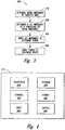
- FIG. 4 illustrates a block diagram of an embodiment of the controller 112 maintaining the power during treatment based on impedance measurements.
- the controller 112 includes a processor 410, a storage component 420 such as a memory, a control component 430, a power supply 440, an input component 450, and an output component 460.
- the control component 430 may contain a routine, algorithm, executable script, or other data structure or program module capable of monitoring impedance and performing actions (e.g., reducing or increasing the power to an energy delivery device) based on reaching or maintaining desired impedance levels, and hence, desired temperature levels.
- the control component 430 may perform a process of controlling the output of power from an energy source 111 to an energy delivery device.
- the controller 112 may be configured to deliver energy in either monopolar or bipolar operation.
- the system may determine the set impedance using parameters related to a target site, energy delivery device, temperature, or other aspects of the treatment.
- Figure 5 schematically illustrates an example of an electrode implementation in an airway 500.
- the airway 500 has an internal passageway 505, and a plurality of electrodes 510 are spaced around the passageway 505.
- the electrodes 510 directly affect discrete target sites 520, 522, 524, 526 on the target area around the passageway 505.
- the spacing of the electrodes 510 and the size (e.g., diameter) of the passageway 505 determine a length L between the discrete sites, and the length L can influence the set impedance based on the initial impedance.
- a shorter length L leads to a higher percentage change between the initial impedance and the set impedance because the distance between adjacent heated target sites is small and the heated sites may be a greater factor in determining the set impedance. With larger lengths L the effect of the heated sites on the set impedance may be lesser. Accordingly, a set impedance value may decrease as an airway diameter decreases and increase as an airway diameter increases.
- the system may empirically determine the set impedance by modeling the size and/or configuration of the electrodes, the size of the passageway, or other aspects related to the target site or the energy delivery device as described above. Additionally, the system may adjust the set impedance based on measuring a time rate of change of the initial impedance, or may adjust the set impedance based on other factors. For example, the system may determine the set impedance by first determining an initial impedance by measuring the initial impedance when applying minimal energy, and comparing the electrode configuration with the initial impedance to arrive at the set impedance. In some cases, the system may review historical or patient information related to a similar electrode size and/or configuration, and use this information when determining the set impedance.
- the system may determine the set impedance based on one or more parameters of a pre-treatment low energy pulse, such as a test pulse.
- the system may calculate the set impedance (Z s ) from one or more parameters of a test pulse, including: (a) the initial pulse impedance (Z o ), (b) the average pulse impedance (Z avg ), (c) the ending pulse impedance (Z end ), (d) the slope of a pulse impedance curve (the rate of change of the pulse impedance) (Z slope ), and (e) the pulse energy, and one or more constants (k 1-6 ).
- the test pulse may be in an energy range from about 0.01 to about 1 joule, having a current pulse amplitude in a range from about 0.01 to about 500 milliamps and a pulse duration in a range from about 0.01 to about 500 milliseconds.
- a constant current pulse is utilized for ease of interpreting impedance changes.
- the temperature and impedance change at the electrode/tissue interface are proportional to the I 2 R heating of adjacent tissue where I is the current amplitude of the pulse and R is the resistance of the adjacent tissue.
- Pulse amplitude and duration may be set to achieve about a 10% change in impedance from start to end of the test pulse.
- Values for the one or more constants may be determined by making a straight line fit of test pulse impedance measurements to steady-state impedance using data taken under temperature control. It will be appreciated however that any number of variations of the test pulse parameters may be utilized to determine the set impedance.
- the system may determine the power to output to an energy delivery device using a PID algorithm, such as an algorithm having one or more variable gain factors.
- a PID algorithm such as an algorithm having one or more variable gain factors.
- FIG 6 a block diagram illustrating an example of a PID algorithm 600 for use in calculating applied power is shown.
- the control component 430 ( Figure 4 ) may be a PID controller that receives impedance value(s) as set points 610.
- the PID controller can correct for errors between the set point and an output value 670, such as a voltage or current, to apply to an energy delivery device by performing three corrections including: (a) a proportional correction 630 that determines a reaction to current error; (b) an integral correction 640 that determines a reaction based on recent error; and (c) a derivative correction 650 that determines a reaction based on the rate of change of the error.
- the algorithm sums the three corrections 660 to output the power value 670. Additionally, the system may recalculate using output values using block 620 in order to continuously update and correct for errors. It will be appreciated that a pre-treatment or test pulse, as describe above, may be added to this impedance control algorithm to determine the set impedance.
- the proportional gain (alpha), the integral gain (beta), and derivative gain (gamma) are constants that may be set based on the method involved, the applied temperature, the type of electrodes, parameters of the targeted site, or other factors.
- the system uses the algorithm 600 to tune the output value to a desired value.
- the PID controller can overshoot the desired set impedance before reaching the set impedance.
- Suitable methods for determining the PID coefficients include empirical methods, the Ziegler-Nichols method, the Cohen-Coon method and software implemented models (e.g., finite element analysis).
- variable gain factor Scales the coefficients (alpha, beta, and gamma; each a function of the three PID parameters) based on, for example, the temperature response to energy input during the initial temperature ramp up. Examples of PID parameters are presented herein, expressed in alpha-beta-gamma space, for the energy delivering device and/or controller. These settings and timings may be based on testing in various lung tissues using an energy delivering apparatus as described above.
- the system changes the relative weights of alpha, beta, and gamma, depending upon monitored temperature and/or impedance response working in either PID or Alpha-Beta-Gamma coordinate space beyond just scaling the alpha-beta-gamma coefficients with a variable gain factor. This can be done by individually adjusting any or all of the alpha, beta, or gamma constants.
- an error value 625 of the PID algorithm E i is set to equal the difference in set impedance and current impedance (Z s - Z i ) during treatment.
- the system may equate the set impedance to be a percentage, generally less than 100% and more typically in a range from about 70 % to about 90 %, of the initial impedance minus an impedance correction using current impedance.
- the system may then calculate the current impedance (Z i ), in order to provide input into the algorithm.
- the PID algorithm may be applied to condition the power supply used to control energy used in treatment, among other benefits.
- FIG. 7 is a chart 700 illustrating a function of temperature and impedance versus time during treatment of tissue.
- temperature 710 and impedance 730 vary inversely as a function of time 720.
- the temperature curve 715 begins to show similarities to the impedance curve 735, at about 60-70 degrees (e.g., 65 degrees) Celsius and about 150-160 Ohms. Both curves 715, 735 remain inversely correlated as time increases to 10 seconds.
- Figure 7 reflects the correlation of impedance and temperature at low temperatures that enables the system to use impedance measurements to control power levels applied to energy delivery devices in a manner that accurately maintains the temperature of the tissue in a desired range (e.g., a constant treatment tissue temperature in a range from 50 to 80 degrees Celsius).
- a desired range e.g., a constant treatment tissue temperature in a range from 50 to 80 degrees Celsius.
- the chart 800 of Figure 8 shows the portion of the chart 700 between 1.8 and 9.8 seconds in greater detail.
- FIG. 8 shows a direct and inverse correlation between impedance and temperature.
- Controlling power based on impedance enables several embodiments of the system to accurately assess the status of the tissue at several regions around the passageway using a variety of catheter and electrode designs. For example, because the system can measure the impedance directly through the electrodes, it does not need to incorporate a thermocouple or other temperature sensor into a catheter. This may reduce the cost, size, and complexity of the energy delivery device compared to using thermocouples. Additionally, the spacing of electrodes may cause error inducing variations in detected temperature versus the actual temperature of the targeted tissue. For example, measured temperatures at each electrode may vary more than measured impedances. Using impedance, the system is able to reduce these variations and deliver a more stable treatment because impedance values may be averaged across all electrodes (e.g., a weighted average or other non-equal weighting between impedance values).
- the impedance correlated to the temperature, may be set at a desired level, such as a percentage of initial impedance.
- the set impedance may be a function of the initial impedance, the size and spacing of the electrodes, the size of a targeted passageway, and other parameters.
- the set impedance may then be entered into a PID algorithm or other control loop algorithm in order to extract a power to be applied to the energy delivery device.
Landscapes
- Health & Medical Sciences (AREA)
- Life Sciences & Earth Sciences (AREA)
- Engineering & Computer Science (AREA)
- Surgery (AREA)
- Biomedical Technology (AREA)
- Nuclear Medicine, Radiotherapy & Molecular Imaging (AREA)
- Animal Behavior & Ethology (AREA)
- General Health & Medical Sciences (AREA)
- Public Health (AREA)
- Veterinary Medicine (AREA)
- Physics & Mathematics (AREA)
- Plasma & Fusion (AREA)
- Otolaryngology (AREA)
- Heart & Thoracic Surgery (AREA)
- Medical Informatics (AREA)
- Molecular Biology (AREA)
- Radiology & Medical Imaging (AREA)
- Neurosurgery (AREA)
- Neurology (AREA)
- Cardiology (AREA)
- Surgical Instruments (AREA)
Claims (14)
- Leistungsregelsystem (100) mit Impedanzrückführung, wobei das System (100) aufweist:eine Energieabgabevorrichtung (120) mit mehreren Elektroden (510), die so konfiguriert sind, dass sie Energie zu jeweiligen Behandlungsstellen abgeben;eine Energieversorgungsvorrichtung, die die Energieabgabevorrichtung (120) speist; undeine Energieversorgungssteuerung (112), die so konfiguriert ist, dass sie die Leistung von der Energieversorgungsvorrichtung zur Energieabgabevorrichtung (120) steuert und eine Regelung der abgegebenen Energie auf der Grundlage der Messung von Impedanzwerten von Zielgewebestellen durchführt, wobei die Steuerung so konfiguriert ist, dass sie die Leistung auf der Grundlage der Impedanzmessungen einstellt, um eine Sollimpedanz und damit die Temperatur in einem gewünschten nicht ablativen Bereich zu halten,dadurch gekennzeichnet, dassdas System so konfiguriert ist, dass es die Sollimpedanz bestimmt, die mit einer gewünschten Behandlungstemperatur oder einem gewünschten Behandlungstemperaturbereich korreliert, und wobei die Steuerung die Sollimpedanz als Funktion einer Anfangsimpedanz sowie der Größe und des variablen Abstands der Elektroden bestimmt.
- System nach Anspruch 1, wobei die Sollimpedanz ein Prozentsatz eines Anfangsimpedanzwerts auf der Grundlage von Spannungs- und Strommessungen in Bezug auf die Energieabgabevorrichtung ist.
- System nach Anspruch 1, wobei die Sollimpedanz zwischen 70 Prozent und 90 Prozent eines Anfangsimpedanzwerts liegt.
- System nach Anspruch 1, wobei die Sollimpedanz ferner auf Kennwerten der Energieabgabevorrichtung beruht.
- System nach Anspruch 1, wobei die Sollimpedanz ferner auf Kennwerten eines Durchgangs beruht, der die Energieabgabevorrichtung während der Behandlung umgibt.
- System nach Anspruch 1, wobei die Sollimpedanz ferner auf einer zeitlichen Änderungsgeschwindigkeit eines Anfangsimpedanzwerts beruht.
- System nach Anspruch 1, wobei die Impedanz ferner auf einer Anfangsimpulsimpedanz, einer mittleren Impulsimpedanz, einer Endimpulsimpedanz, einer Änderungsgeschwindigkeit der Impulsimpedanz oder einer Impulsenergie beruht.
- System nach Anspruch 1, wobei:die Energieabgabevorrichtung einen länglichen Körper und eine Elektrodeneinheit mit mehreren Elektroden hat; unddie Energieversorgungssteuerung eine Steuervorrichtung aufweist, die Leistung zur Energieabgabevorrichtung auf der Grundlage einer Differenz zwischen einer Sollimpedanz und einer Istimpedanz ausgibt.
- System nach Anspruch 8, wobei die Steuervorrichtung einen PID-Algorithmus aufweist, der einen Ausgangsleistungswert auf der Grundlage der Differenz zwischen der Sollimpedanz und einer Istimpedanz bestimmt.
- System nach Anspruch 8, wobei eine Anfangsimpedanz auf der Geometrie der Elektroden beruht.
- System nach Anspruch 8, wobei die Regelvorrichtung so konfiguriert ist, dass sie Energie für eine Aktivierungszeitspanne unter 20 Sekunden abgibt.
- System nach Anspruch 8, wobei die Sollimpedanz mit einer Temperatur im Bereich von 50 bis 80 Grad Celsius korreliert.
- System nach Anspruch 8, wobei die Ausgangsleistung unter 40 Watt liegt.
- System nach Anspruch 8, wobei die Energie Hochfrequenzenergie aufweist.
Applications Claiming Priority (2)
| Application Number | Priority Date | Filing Date | Title |
|---|---|---|---|
| US95165507P | 2007-07-24 | 2007-07-24 | |
| PCT/US2008/071037 WO2009015278A1 (en) | 2007-07-24 | 2008-07-24 | System and method for controlling power based on impedance detection, such as controlling power to tissue treatment devices |
Publications (3)
| Publication Number | Publication Date |
|---|---|
| EP2180917A1 EP2180917A1 (de) | 2010-05-05 |
| EP2180917A4 EP2180917A4 (de) | 2013-01-23 |
| EP2180917B1 true EP2180917B1 (de) | 2018-01-24 |
Family
ID=40281823
Family Applications (1)
| Application Number | Title | Priority Date | Filing Date |
|---|---|---|---|
| EP08796555.4A Active EP2180917B1 (de) | 2007-07-24 | 2008-07-24 | System zur leistungssteuerung auf der basis von impedanzerkennung, wie etwa leistungssteuerung bei gewebebehandlungsgeräten |
Country Status (6)
| Country | Link |
|---|---|
| US (4) | US9108052B2 (de) |
| EP (1) | EP2180917B1 (de) |
| JP (2) | JP5436423B2 (de) |
| AU (1) | AU2008279121B2 (de) |
| CA (1) | CA2694438C (de) |
| WO (1) | WO2009015278A1 (de) |
Families Citing this family (91)
| Publication number | Priority date | Publication date | Assignee | Title |
|---|---|---|---|---|
| US7027869B2 (en) * | 1998-01-07 | 2006-04-11 | Asthmatx, Inc. | Method for treating an asthma attack |
| US7425212B1 (en) * | 1998-06-10 | 2008-09-16 | Asthmatx, Inc. | Devices for modification of airways by transfer of energy |
| US7992572B2 (en) | 1998-06-10 | 2011-08-09 | Asthmatx, Inc. | Methods of evaluating individuals having reversible obstructive pulmonary disease |
| US6634363B1 (en) | 1997-04-07 | 2003-10-21 | Broncus Technologies, Inc. | Methods of treating lungs having reversible obstructive pulmonary disease |
| US6488673B1 (en) * | 1997-04-07 | 2002-12-03 | Broncus Technologies, Inc. | Method of increasing gas exchange of a lung |
| US7921855B2 (en) * | 1998-01-07 | 2011-04-12 | Asthmatx, Inc. | Method for treating an asthma attack |
| US7198635B2 (en) | 2000-10-17 | 2007-04-03 | Asthmatx, Inc. | Modification of airways by application of energy |
| US8181656B2 (en) | 1998-06-10 | 2012-05-22 | Asthmatx, Inc. | Methods for treating airways |
| US20070123958A1 (en) * | 1998-06-10 | 2007-05-31 | Asthmatx, Inc. | Apparatus for treating airways in the lung |
| US8251070B2 (en) | 2000-03-27 | 2012-08-28 | Asthmatx, Inc. | Methods for treating airways |
| US7104987B2 (en) | 2000-10-17 | 2006-09-12 | Asthmatx, Inc. | Control system and process for application of energy to airway walls and other mediums |
| US20040226556A1 (en) | 2003-05-13 | 2004-11-18 | Deem Mark E. | Apparatus for treating asthma using neurotoxin |
| CA2605360C (en) | 2005-04-21 | 2017-03-28 | Asthmatx, Inc. | Control methods and devices for energy delivery |
| US12220165B2 (en) | 2005-04-21 | 2025-02-11 | Boston Scientific Scimed, Inc. | Control methods and devices for energy delivery |
| PL2037840T3 (pl) | 2006-06-28 | 2012-09-28 | Medtronic Ardian Luxembourg | Systemy do termicznie indukowanej neuromodulacji nerek |
| US8845630B2 (en) * | 2007-06-15 | 2014-09-30 | Syneron Medical Ltd | Devices and methods for percutaneous energy delivery |
| JP5436423B2 (ja) * | 2007-07-24 | 2014-03-05 | アスマティックス,インコーポレイテッド | 組織治療装置への電力制御等のインピーダンス検出に基づく電力制御のシステムおよび方法 |
| US8322335B2 (en) | 2007-10-22 | 2012-12-04 | Uptake Medical Corp. | Determining patient-specific vapor treatment and delivery parameters |
| US8906011B2 (en) | 2007-11-16 | 2014-12-09 | Kardium Inc. | Medical device for use in bodily lumens, for example an atrium |
| US8483831B1 (en) | 2008-02-15 | 2013-07-09 | Holaira, Inc. | System and method for bronchial dilation |
| KR101719824B1 (ko) | 2008-05-09 | 2017-04-04 | 호라이라 인코포레이티드 | 기관지나무 치료용 시스템, 어셈블리 및 방법 |
| GB2465581B (en) * | 2008-11-20 | 2013-03-20 | Synapse Microcurrent Ltd | Method and device for verifying the electrical output of a microcurrent therapy device |
| US8167875B2 (en) * | 2009-01-12 | 2012-05-01 | Tyco Healthcare Group Lp | Energy delivery algorithm for medical devices |
| DE102009024612A1 (de) * | 2009-06-10 | 2010-12-16 | Erbe Elektromedizin Gmbh | Versorgungseinrichtung zur Bereitstellung einer HF-Ausgangsspannung, HF-Chirurgiegerät mit entsprechender Versorgungseinrichtung und Verfahren zum Betreiben einer HF-Generatoreinheit |
| CN107049479B (zh) | 2009-10-27 | 2020-10-16 | 努瓦拉公司 | 具有可冷却的能量发射组件的递送装置 |
| CN106618731B (zh) | 2009-11-11 | 2020-08-07 | 努瓦拉公司 | 用于处理组织和控制狭窄的系统、装置和方法 |
| US8911439B2 (en) | 2009-11-11 | 2014-12-16 | Holaira, Inc. | Non-invasive and minimally invasive denervation methods and systems for performing the same |
| US8764744B2 (en) * | 2010-01-25 | 2014-07-01 | Covidien Lp | System for monitoring ablation size |
| CN103313671B (zh) | 2010-10-25 | 2017-06-06 | 美敦力Af卢森堡有限责任公司 | 用于神经调节治疗的估算及反馈的装置、系统及方法 |
| US9480525B2 (en) | 2011-01-21 | 2016-11-01 | Kardium, Inc. | High-density electrode-based medical device system |
| US9452016B2 (en) | 2011-01-21 | 2016-09-27 | Kardium Inc. | Catheter system |
| CA2764494A1 (en) | 2011-01-21 | 2012-07-21 | Kardium Inc. | Enhanced medical device for use in bodily cavities, for example an atrium |
| US11259867B2 (en) | 2011-01-21 | 2022-03-01 | Kardium Inc. | High-density electrode-based medical device system |
| US9265557B2 (en) | 2011-01-31 | 2016-02-23 | Medtronic Ablation Frontiers Llc | Multi frequency and multi polarity complex impedance measurements to assess ablation lesions |
| SG195499A1 (en) | 2012-05-22 | 2013-12-30 | Agency Science Tech & Res | Stimulator and method for processing a stimulation signal |
| US9770293B2 (en) | 2012-06-04 | 2017-09-26 | Boston Scientific Scimed, Inc. | Systems and methods for treating tissue of a passageway within a body |
| US9592086B2 (en) | 2012-07-24 | 2017-03-14 | Boston Scientific Scimed, Inc. | Electrodes for tissue treatment |
| CA2878253A1 (en) * | 2012-09-26 | 2014-04-03 | Boston Scientific Scimed, Inc. | Systems and methods for controlling energy application |
| US9272132B2 (en) | 2012-11-02 | 2016-03-01 | Boston Scientific Scimed, Inc. | Medical device for treating airways and related methods of use |
| WO2014071372A1 (en) | 2012-11-05 | 2014-05-08 | Boston Scientific Scimed, Inc. | Devices for delivering energy to body lumens |
| US9398933B2 (en) | 2012-12-27 | 2016-07-26 | Holaira, Inc. | Methods for improving drug efficacy including a combination of drug administration and nerve modulation |
| US9504516B2 (en) | 2013-05-31 | 2016-11-29 | Covidien LLP | Gain compensation for a full bridge inverter |
| WO2014201113A1 (en) | 2013-06-11 | 2014-12-18 | St. Jude Medical, Atrial Fibrillation Division, Inc. | Multi-electrode impedance sensing |
| US9872719B2 (en) | 2013-07-24 | 2018-01-23 | Covidien Lp | Systems and methods for generating electrosurgical energy using a multistage power converter |
| US9636165B2 (en) | 2013-07-29 | 2017-05-02 | Covidien Lp | Systems and methods for measuring tissue impedance through an electrosurgical cable |
| CA2913220A1 (en) | 2013-08-09 | 2015-02-12 | Boston Scientific Scimed, Inc. | Expandable catheter and related methods of manufacture and use |
| US9782211B2 (en) | 2013-10-01 | 2017-10-10 | Uptake Medical Technology Inc. | Preferential volume reduction of diseased segments of a heterogeneous lobe |
| US10433902B2 (en) | 2013-10-23 | 2019-10-08 | Medtronic Ardian Luxembourg S.A.R.L. | Current control methods and systems |
| EP3122414B1 (de) | 2014-03-26 | 2021-03-17 | Venclose, Inc. | Kabelanordnung |
| US10610292B2 (en) | 2014-04-25 | 2020-04-07 | Medtronic Ardian Luxembourg S.A.R.L. | Devices, systems, and methods for monitoring and/or controlling deployment of a neuromodulation element within a body lumen and related technology |
| PL3011923T3 (pl) * | 2014-10-23 | 2022-02-14 | Erbe Elektromedizin Gmbh | Urządzenie do wykrywania metalu podczas oddziaływania na tkankę biologiczną za pomocą wytwarzającego iskrę instrumentu elektrochirurgicznego |
| US10485604B2 (en) | 2014-12-02 | 2019-11-26 | Uptake Medical Technology Inc. | Vapor treatment of lung nodules and tumors |
| US10531906B2 (en) | 2015-02-02 | 2020-01-14 | Uptake Medical Technology Inc. | Medical vapor generator |
| US10143399B2 (en) | 2015-04-02 | 2018-12-04 | Medtronic Ablation Frontiers Llc | Tissue contact sensing with a multi electrode ablation catheter |
| US10182742B2 (en) | 2015-04-02 | 2019-01-22 | Medtronic Ablation Frontiers Llc | Tissue contact sensing with a multi electrode ablation catheter |
| US10993765B2 (en) * | 2015-06-30 | 2021-05-04 | Smith & Nephew, Inc. | Temperature measurement of electrically conductive fluids |
| US10285751B2 (en) * | 2015-10-16 | 2019-05-14 | Biosense Webster (Israel) Ltd. | System and method for controlling catheter power based on renal ablation response |
| US10470791B2 (en) | 2015-12-30 | 2019-11-12 | Ethicon Llc | Surgical instrument with staged application of electrosurgical and ultrasonic energy |
| US10350423B2 (en) | 2016-02-04 | 2019-07-16 | Cardiac Pacemakers, Inc. | Delivery system with force sensor for leadless cardiac device |
| US10925512B2 (en) * | 2016-03-10 | 2021-02-23 | Boston Scientific Scimed, Inc. | Use of low-power RF energy for tissue diagnosis |
| CN109310465B (zh) | 2016-05-03 | 2021-08-03 | 圣犹达医疗用品心脏病学部门有限公司 | 部分地基于组织定征的损伤预测 |
| DK3474760T3 (da) | 2016-06-27 | 2023-03-20 | Galvanize Therapeutics Inc | Generator og et kateter med en elektrode til at behandle en lungepassage |
| US12403305B2 (en) | 2016-06-27 | 2025-09-02 | Galvanize Therapeutics, Inc. | Immunostimulation in the treatment of viral infection |
| WO2018106939A1 (en) * | 2016-12-07 | 2018-06-14 | Nuvaira, Inc. | Method and systems for reducing treatment variability and increasing treatment efficacy and durability |
| KR20180111203A (ko) | 2017-03-31 | 2018-10-11 | 주식회사 루트로닉 | Rf치료기기, rf치료기기의 제어방법 및 rf에너지를 이용한 피부치료방법 |
| KR20180111202A (ko) * | 2017-03-31 | 2018-10-11 | 주식회사 루트로닉 | Rf치료기기, rf치료기기의 제어방법 및 rf에너지를 이용한 피부치료방법 |
| KR102287415B1 (ko) * | 2017-03-31 | 2021-08-11 | 주식회사 루트로닉 | Rf치료기기 |
| US11129673B2 (en) | 2017-05-05 | 2021-09-28 | Uptake Medical Technology Inc. | Extra-airway vapor ablation for treating airway constriction in patients with asthma and COPD |
| US10610296B2 (en) * | 2017-05-31 | 2020-04-07 | Biosense Webster (Israel) Ltd. | Cardiac electrophysiology machine including catheter stability while estimating impedance drop |
| US11344364B2 (en) | 2017-09-07 | 2022-05-31 | Uptake Medical Technology Inc. | Screening method for a target nerve to ablate for the treatment of inflammatory lung disease |
| CN109464186B (zh) | 2017-09-08 | 2023-12-22 | 泽丹医疗股份有限公司 | 治疗肺部肿瘤的装置和方法 |
| US11350988B2 (en) | 2017-09-11 | 2022-06-07 | Uptake Medical Technology Inc. | Bronchoscopic multimodality lung tumor treatment |
| USD845467S1 (en) | 2017-09-17 | 2019-04-09 | Uptake Medical Technology Inc. | Hand-piece for medical ablation catheter |
| US11419658B2 (en) | 2017-11-06 | 2022-08-23 | Uptake Medical Technology Inc. | Method for treating emphysema with condensable thermal vapor |
| US11490946B2 (en) | 2017-12-13 | 2022-11-08 | Uptake Medical Technology Inc. | Vapor ablation handpiece |
| US12082917B2 (en) | 2018-01-24 | 2024-09-10 | Medtronic Ireland Manufacturing Unlimited Company | Systems, devices, and methods for assessing efficacy of renal neuromodulation therapy |
| US12064622B2 (en) | 2018-03-30 | 2024-08-20 | Minnetronix, Inc. | Medical devices for ablating tissue |
| US11864812B2 (en) * | 2018-09-05 | 2024-01-09 | Applied Medical Resources Corporation | Electrosurgical generator control system |
| US11653927B2 (en) | 2019-02-18 | 2023-05-23 | Uptake Medical Technology Inc. | Vapor ablation treatment of obstructive lung disease |
| US11806522B2 (en) | 2020-05-05 | 2023-11-07 | Cynosure, Llc | Needle-array devices and related methods |
| US12226143B2 (en) | 2020-06-22 | 2025-02-18 | Covidien Lp | Universal surgical footswitch toggling |
| US20220008113A1 (en) * | 2020-07-09 | 2022-01-13 | Advanced Neuromodulation Systems, Inc. | Systems and methods for temperature control in rf ablation systems |
| CN112244993B (zh) * | 2020-10-31 | 2022-03-15 | 杭州诺生医疗科技有限公司 | 射频消融仪 |
| CN113143443B (zh) * | 2020-12-31 | 2022-09-27 | 杭州堃博生物科技有限公司 | 多电极射频探头的功率调整方法和射频主机 |
| CN112791262B (zh) * | 2020-12-31 | 2023-02-03 | 杭州堃博生物科技有限公司 | 射频操作数据调控方法、装置及注射泵 |
| US11931587B2 (en) * | 2021-07-06 | 2024-03-19 | Pacesetter, Inc. | Method and system for implanting a septal wall electrode |
| CN114191707B (zh) * | 2021-12-15 | 2022-12-23 | 广东花至美容科技有限公司 | 基于皮肤阻抗的美容仪射频功率控制方法及设备 |
| CN114191708B (zh) * | 2021-12-15 | 2023-12-05 | 广东花至美容科技有限公司 | 美容仪射频输出功率控制方法、存储介质及电子设备 |
| CN114879804A (zh) * | 2022-04-12 | 2022-08-09 | 林镇清 | 电子设备的功率调节方法、装置、设备和存储介质 |
| JP2025149131A (ja) * | 2024-03-26 | 2025-10-08 | 日本ライフライン株式会社 | 電源装置およびアブレーションシステム |
| CN120501500B (zh) * | 2025-07-22 | 2025-09-16 | 苏州飞马医疗科技有限公司 | 一种高频加热蒸汽消融设备用动态功率分配系统 |
Family Cites Families (73)
| Publication number | Priority date | Publication date | Assignee | Title |
|---|---|---|---|---|
| JPS59167707A (ja) | 1983-03-14 | 1984-09-21 | Toshiba Corp | サンプル値制御装置 |
| US4739759A (en) * | 1985-02-26 | 1988-04-26 | Concept, Inc. | Microprocessor controlled electrosurgical generator |
| US4907589A (en) * | 1988-04-29 | 1990-03-13 | Cosman Eric R | Automatic over-temperature control apparatus for a therapeutic heating device |
| JPH0522345A (ja) * | 1991-07-12 | 1993-01-29 | Hitachi Ltd | 最大転送単位の最適値管理決定方式 |
| US5540681A (en) * | 1992-04-10 | 1996-07-30 | Medtronic Cardiorhythm | Method and system for radiofrequency ablation of tissue |
| US5662108A (en) * | 1992-09-23 | 1997-09-02 | Endocardial Solutions, Inc. | Electrophysiology mapping system |
| WO1994010922A1 (en) * | 1992-11-13 | 1994-05-26 | Ep Technologies, Inc. | Cardial ablation systems using temperature monitoring |
| DE69432252T2 (de) | 1993-04-30 | 2003-12-18 | Ethicon Endo-Surgery, Cincinnati | Elektrochirurgisches impedanzrückkopplungssystem |
| US5496312A (en) * | 1993-10-07 | 1996-03-05 | Valleylab Inc. | Impedance and temperature generator control |
| US5447529A (en) * | 1994-01-28 | 1995-09-05 | Philadelphia Heart Institute | Method of using endocardial impedance for determining electrode-tissue contact, appropriate sites for arrhythmia ablation and tissue heating during ablation |
| US6092528A (en) * | 1994-06-24 | 2000-07-25 | Edwards; Stuart D. | Method to treat esophageal sphincters |
| WO1996000528A1 (en) * | 1994-06-27 | 1996-01-11 | Ep Technologies, Inc. | Non-linear control systems and methods for heating and ablating body tissue |
| US5735846A (en) * | 1994-06-27 | 1998-04-07 | Ep Technologies, Inc. | Systems and methods for ablating body tissue using predicted maximum tissue temperature |
| US5688267A (en) | 1995-05-01 | 1997-11-18 | Ep Technologies, Inc. | Systems and methods for sensing multiple temperature conditions during tissue ablation |
| US6575969B1 (en) * | 1995-05-04 | 2003-06-10 | Sherwood Services Ag | Cool-tip radiofrequency thermosurgery electrode system for tumor ablation |
| US5782827A (en) * | 1995-08-15 | 1998-07-21 | Rita Medical Systems, Inc. | Multiple antenna ablation apparatus and method with multiple sensor feedback |
| US5837001A (en) * | 1995-12-08 | 1998-11-17 | C. R. Bard | Radio frequency energy delivery system for multipolar electrode catheters |
| US5925038A (en) * | 1996-01-19 | 1999-07-20 | Ep Technologies, Inc. | Expandable-collapsible electrode structures for capacitive coupling to tissue |
| US6152899A (en) | 1996-03-05 | 2000-11-28 | Vnus Medical Technologies, Inc. | Expandable catheter having improved electrode design, and method for applying energy |
| US5755760A (en) * | 1996-03-11 | 1998-05-26 | Medtronic, Inc. | Deflectable catheter |
| US6458121B1 (en) * | 1996-03-19 | 2002-10-01 | Diapulse Corporation Of America | Apparatus for athermapeutic medical treatments |
| AUPN957296A0 (en) * | 1996-04-30 | 1996-05-23 | Cardiac Crc Nominees Pty Limited | A system for simultaneous unipolar multi-electrode ablation |
| US6063078A (en) * | 1997-03-12 | 2000-05-16 | Medtronic, Inc. | Method and apparatus for tissue ablation |
| US7027869B2 (en) * | 1998-01-07 | 2006-04-11 | Asthmatx, Inc. | Method for treating an asthma attack |
| US6411852B1 (en) * | 1997-04-07 | 2002-06-25 | Broncus Technologies, Inc. | Modification of airways by application of energy |
| US6634363B1 (en) * | 1997-04-07 | 2003-10-21 | Broncus Technologies, Inc. | Methods of treating lungs having reversible obstructive pulmonary disease |
| US6033399A (en) * | 1997-04-09 | 2000-03-07 | Valleylab, Inc. | Electrosurgical generator with adaptive power control |
| US6104954A (en) * | 1997-06-30 | 2000-08-15 | Blunsden; Christopher K. | High frequency lead testing apparatus in an implantable defibrillator |
| US6283987B1 (en) * | 1998-01-14 | 2001-09-04 | Surx, Inc. | Ribbed electrodes and methods for their use |
| EP0908713A1 (de) | 1997-10-06 | 1999-04-14 | Claud S. Gordon Company | Mit Temperaturinstrumenten versehene Halbleiterscheibe |
| US6071281A (en) * | 1998-05-05 | 2000-06-06 | Ep Technologies, Inc. | Surgical method and apparatus for positioning a diagnostic or therapeutic element within the body and remote power control unit for use with same |
| US6355031B1 (en) * | 1998-02-19 | 2002-03-12 | Curon Medical, Inc. | Control systems for multiple electrode arrays to create lesions in tissue regions at or near a sphincter |
| US6558378B2 (en) * | 1998-05-05 | 2003-05-06 | Cardiac Pacemakers, Inc. | RF ablation system and method having automatic temperature control |
| US7198635B2 (en) * | 2000-10-17 | 2007-04-03 | Asthmatx, Inc. | Modification of airways by application of energy |
| US6245065B1 (en) * | 1998-09-10 | 2001-06-12 | Scimed Life Systems, Inc. | Systems and methods for controlling power in an electrosurgical probe |
| US6183468B1 (en) * | 1998-09-10 | 2001-02-06 | Scimed Life Systems, Inc. | Systems and methods for controlling power in an electrosurgical probe |
| US6123702A (en) * | 1998-09-10 | 2000-09-26 | Scimed Life Systems, Inc. | Systems and methods for controlling power in an electrosurgical probe |
| US6423057B1 (en) * | 1999-01-25 | 2002-07-23 | The Arizona Board Of Regents On Behalf Of The University Of Arizona | Method and apparatus for monitoring and controlling tissue temperature and lesion formation in radio-frequency ablation procedures |
| US6939346B2 (en) * | 1999-04-21 | 2005-09-06 | Oratec Interventions, Inc. | Method and apparatus for controlling a temperature-controlled probe |
| JP2001037776A (ja) | 1999-07-26 | 2001-02-13 | Olympus Optical Co Ltd | 治療装置 |
| US6264653B1 (en) * | 1999-09-24 | 2001-07-24 | C. R. Band, Inc. | System and method for gauging the amount of electrode-tissue contact using pulsed radio frequency energy |
| US20030069570A1 (en) * | 1999-10-02 | 2003-04-10 | Witzel Thomas H. | Methods for repairing mitral valve annulus percutaneously |
| JP3989166B2 (ja) * | 2000-08-31 | 2007-10-10 | オリンパス株式会社 | 電気手術装置 |
| US6730080B2 (en) | 2000-08-23 | 2004-05-04 | Olympus Corporation | Electric operation apparatus |
| US6640120B1 (en) * | 2000-10-05 | 2003-10-28 | Scimed Life Systems, Inc. | Probe assembly for mapping and ablating pulmonary vein tissue and method of using same |
| ATE313299T1 (de) * | 2000-10-17 | 2006-01-15 | Asthmatx Inc | Modifikation der luftwege durch anwendung von energie |
| US7104987B2 (en) * | 2000-10-17 | 2006-09-12 | Asthmatx, Inc. | Control system and process for application of energy to airway walls and other mediums |
| US20020087151A1 (en) | 2000-12-29 | 2002-07-04 | Afx, Inc. | Tissue ablation apparatus with a sliding ablation instrument and method |
| US7422586B2 (en) * | 2001-02-28 | 2008-09-09 | Angiodynamics, Inc. | Tissue surface treatment apparatus and method |
| US6648883B2 (en) * | 2001-04-26 | 2003-11-18 | Medtronic, Inc. | Ablation system and method of use |
| CN100518685C (zh) * | 2001-05-10 | 2009-07-29 | 脉管动力股份有限公司 | 组织消融设备 |
| ATE320767T1 (de) * | 2001-09-28 | 2006-04-15 | Rita Medical Systems Inc | Impedanzgesteuerte vorrichtung zur ablation von gewebe |
| US6635056B2 (en) * | 2001-10-09 | 2003-10-21 | Cardiac Pacemakers, Inc. | RF ablation apparatus and method using amplitude control |
| US20030153905A1 (en) * | 2002-01-25 | 2003-08-14 | Edwards Stuart Denzil | Selective ablation system |
| US6733498B2 (en) * | 2002-02-19 | 2004-05-11 | Live Tissue Connect, Inc. | System and method for control of tissue welding |
| US7294127B2 (en) * | 2002-03-05 | 2007-11-13 | Baylis Medical Company Inc. | Electrosurgical tissue treatment method |
| US6588267B1 (en) * | 2002-03-12 | 2003-07-08 | Titan Specialties, Ltd. | Isolator bar for acoustic instruments used in downhole formations |
| US20030187430A1 (en) * | 2002-03-15 | 2003-10-02 | Vorisek James C. | System and method for measuring power at tissue during RF ablation |
| US7756583B2 (en) * | 2002-04-08 | 2010-07-13 | Ardian, Inc. | Methods and apparatus for intravascularly-induced neuromodulation |
| DE10218894A1 (de) * | 2002-04-26 | 2003-11-13 | Storz Endoskop Prod Gmbh | Vorrichtung zur Überwachung medizinischer Geräte |
| US6887237B2 (en) * | 2002-07-22 | 2005-05-03 | Medtronic, Inc. | Method for treating tissue with a wet electrode and apparatus for using same |
| US20040153056A1 (en) * | 2002-11-11 | 2004-08-05 | Berchtold Holding Gmbh, A German Corporation | Probe |
| US7131445B2 (en) * | 2002-12-23 | 2006-11-07 | Gyrus Medical Limited | Electrosurgical method and apparatus |
| US20050096644A1 (en) * | 2003-10-30 | 2005-05-05 | Hall Jeffrey A. | Energy delivery optimization for RF duty cycle for lesion creation |
| US7377918B2 (en) * | 2004-04-28 | 2008-05-27 | Gyrus Medical Limited | Electrosurgical method and apparatus |
| US7553309B2 (en) * | 2004-10-08 | 2009-06-30 | Covidien Ag | Electrosurgical system employing multiple electrodes and method thereof |
| US7949407B2 (en) * | 2004-11-05 | 2011-05-24 | Asthmatx, Inc. | Energy delivery devices and methods |
| US8617152B2 (en) * | 2004-11-15 | 2013-12-31 | Medtronic Ablation Frontiers Llc | Ablation system with feedback |
| ES2796627T3 (es) * | 2005-01-18 | 2020-11-27 | S D M H Pty Ltd | Dispositivo para ablación térmica de tejido biológico usando patrones de ablación esférica |
| CA2605360C (en) * | 2005-04-21 | 2017-03-28 | Asthmatx, Inc. | Control methods and devices for energy delivery |
| ES2722849T3 (es) * | 2006-10-13 | 2019-08-19 | Cyberonics Inc | Dispositivos y sistemas para el tratamiento de apnea obstructiva del sueño |
| US7931647B2 (en) * | 2006-10-20 | 2011-04-26 | Asthmatx, Inc. | Method of delivering energy to a lung airway using markers |
| JP5436423B2 (ja) * | 2007-07-24 | 2014-03-05 | アスマティックス,インコーポレイテッド | 組織治療装置への電力制御等のインピーダンス検出に基づく電力制御のシステムおよび方法 |
-
2008
- 2008-07-24 JP JP2010518387A patent/JP5436423B2/ja not_active Expired - Fee Related
- 2008-07-24 WO PCT/US2008/071037 patent/WO2009015278A1/en not_active Ceased
- 2008-07-24 CA CA2694438A patent/CA2694438C/en not_active Expired - Fee Related
- 2008-07-24 EP EP08796555.4A patent/EP2180917B1/de active Active
- 2008-07-24 AU AU2008279121A patent/AU2008279121B2/en not_active Ceased
- 2008-07-24 US US12/179,301 patent/US9108052B2/en active Active
-
2013
- 2013-10-10 JP JP2013212557A patent/JP5732507B2/ja not_active Expired - Fee Related
-
2015
- 2015-07-14 US US14/799,346 patent/US10278765B2/en active Active
-
2019
- 2019-03-26 US US16/364,518 patent/US11534229B2/en active Active
-
2022
- 2022-11-22 US US18/057,863 patent/US12390263B2/en active Active
Non-Patent Citations (1)
| Title |
|---|
| None * |
Also Published As
| Publication number | Publication date |
|---|---|
| US20150313664A1 (en) | 2015-11-05 |
| JP5732507B2 (ja) | 2015-06-10 |
| US20230098737A1 (en) | 2023-03-30 |
| US10278765B2 (en) | 2019-05-07 |
| US20090030477A1 (en) | 2009-01-29 |
| CA2694438A1 (en) | 2009-01-29 |
| JP2014004482A (ja) | 2014-01-16 |
| US11534229B2 (en) | 2022-12-27 |
| US12390263B2 (en) | 2025-08-19 |
| AU2008279121A1 (en) | 2009-01-29 |
| EP2180917A1 (de) | 2010-05-05 |
| AU2008279121B2 (en) | 2013-09-19 |
| JP2010534527A (ja) | 2010-11-11 |
| EP2180917A4 (de) | 2013-01-23 |
| US20190216527A1 (en) | 2019-07-18 |
| CA2694438C (en) | 2016-08-16 |
| JP5436423B2 (ja) | 2014-03-05 |
| US9108052B2 (en) | 2015-08-18 |
| WO2009015278A1 (en) | 2009-01-29 |
Similar Documents
| Publication | Publication Date | Title |
|---|---|---|
| US12390263B2 (en) | System and method for controlling power based on impedance detection, such as controlling power to tissue treatment devices | |
| US10016592B2 (en) | Control system and process for application of energy to airway walls and other mediums | |
| EP1326548B1 (de) | Kontrollsystem und -verfahren für die energiezufuhr zu luftwegewänden oder anderen medien | |
| US20140088588A1 (en) | Systems and methods for controlling energy application | |
| US20110152857A1 (en) | Apparatus and Methods For Electrophysiology Procedures | |
| US9770293B2 (en) | Systems and methods for treating tissue of a passageway within a body | |
| AU2002211779A1 (en) | Control system and process for application of energy to airway walls and other mediums | |
| IL275672B1 (en) | Myocardial tissue ablation with narrow temperature variation | |
| US20140031808A1 (en) | Medical device tracking and energy feedback |
Legal Events
| Date | Code | Title | Description |
|---|---|---|---|
| PUAI | Public reference made under article 153(3) epc to a published international application that has entered the european phase |
Free format text: ORIGINAL CODE: 0009012 |
|
| 17P | Request for examination filed |
Effective date: 20100222 |
|
| AK | Designated contracting states |
Kind code of ref document: A1 Designated state(s): AT BE BG CH CY CZ DE DK EE ES FI FR GB GR HR HU IE IS IT LI LT LU LV MC MT NL NO PL PT RO SE SI SK TR |
|
| AX | Request for extension of the european patent |
Extension state: AL BA MK RS |
|
| DAX | Request for extension of the european patent (deleted) | ||
| A4 | Supplementary search report drawn up and despatched |
Effective date: 20121221 |
|
| RIC1 | Information provided on ipc code assigned before grant |
Ipc: A61B 18/12 20060101ALI20121217BHEP Ipc: A61N 1/00 20060101AFI20121217BHEP Ipc: A61N 1/32 20060101ALI20121217BHEP |
|
| 17Q | First examination report despatched |
Effective date: 20140211 |
|
| REG | Reference to a national code |
Ref country code: DE Ref legal event code: R079 Ref document number: 602008053874 Country of ref document: DE Free format text: PREVIOUS MAIN CLASS: A61N0001000000 Ipc: A61B0018140000 |
|
| RIC1 | Information provided on ipc code assigned before grant |
Ipc: A61B 18/14 20060101AFI20170117BHEP Ipc: A61B 18/00 20060101ALI20170117BHEP Ipc: A61B 18/12 20060101ALI20170117BHEP Ipc: A61N 1/32 20060101ALI20170117BHEP Ipc: A61N 1/36 20060101ALI20170117BHEP |
|
| RAP1 | Party data changed (applicant data changed or rights of an application transferred) |
Owner name: BOSTON SCIENTIFIC SCIMED, INC. |
|
| GRAP | Despatch of communication of intention to grant a patent |
Free format text: ORIGINAL CODE: EPIDOSNIGR1 |
|
| INTG | Intention to grant announced |
Effective date: 20170324 |
|
| GRAJ | Information related to disapproval of communication of intention to grant by the applicant or resumption of examination proceedings by the epo deleted |
Free format text: ORIGINAL CODE: EPIDOSDIGR1 |
|
| GRAP | Despatch of communication of intention to grant a patent |
Free format text: ORIGINAL CODE: EPIDOSNIGR1 |
|
| INTC | Intention to grant announced (deleted) | ||
| INTG | Intention to grant announced |
Effective date: 20170818 |
|
| GRAS | Grant fee paid |
Free format text: ORIGINAL CODE: EPIDOSNIGR3 |
|
| GRAA | (expected) grant |
Free format text: ORIGINAL CODE: 0009210 |
|
| AK | Designated contracting states |
Kind code of ref document: B1 Designated state(s): AT BE BG CH CY CZ DE DK EE ES FI FR GB GR HR HU IE IS IT LI LT LU LV MC MT NL NO PL PT RO SE SI SK TR |
|
| REG | Reference to a national code |
Ref country code: GB Ref legal event code: FG4D |
|
| REG | Reference to a national code |
Ref country code: CH Ref legal event code: EP |
|
| REG | Reference to a national code |
Ref country code: AT Ref legal event code: REF Ref document number: 965321 Country of ref document: AT Kind code of ref document: T Effective date: 20180215 |
|
| REG | Reference to a national code |
Ref country code: IE Ref legal event code: FG4D |
|
| REG | Reference to a national code |
Ref country code: DE Ref legal event code: R096 Ref document number: 602008053874 Country of ref document: DE |
|
| REG | Reference to a national code |
Ref country code: NL Ref legal event code: MP Effective date: 20180124 |
|
| REG | Reference to a national code |
Ref country code: LT Ref legal event code: MG4D |
|
| REG | Reference to a national code |
Ref country code: FR Ref legal event code: PLFP Year of fee payment: 11 |
|
| REG | Reference to a national code |
Ref country code: AT Ref legal event code: MK05 Ref document number: 965321 Country of ref document: AT Kind code of ref document: T Effective date: 20180124 |
|
| PG25 | Lapsed in a contracting state [announced via postgrant information from national office to epo] |
Ref country code: NL Free format text: LAPSE BECAUSE OF FAILURE TO SUBMIT A TRANSLATION OF THE DESCRIPTION OR TO PAY THE FEE WITHIN THE PRESCRIBED TIME-LIMIT Effective date: 20180124 |
|
| PG25 | Lapsed in a contracting state [announced via postgrant information from national office to epo] |
Ref country code: ES Free format text: LAPSE BECAUSE OF FAILURE TO SUBMIT A TRANSLATION OF THE DESCRIPTION OR TO PAY THE FEE WITHIN THE PRESCRIBED TIME-LIMIT Effective date: 20180124 Ref country code: HR Free format text: LAPSE BECAUSE OF FAILURE TO SUBMIT A TRANSLATION OF THE DESCRIPTION OR TO PAY THE FEE WITHIN THE PRESCRIBED TIME-LIMIT Effective date: 20180124 Ref country code: NO Free format text: LAPSE BECAUSE OF FAILURE TO SUBMIT A TRANSLATION OF THE DESCRIPTION OR TO PAY THE FEE WITHIN THE PRESCRIBED TIME-LIMIT Effective date: 20180424 Ref country code: LT Free format text: LAPSE BECAUSE OF FAILURE TO SUBMIT A TRANSLATION OF THE DESCRIPTION OR TO PAY THE FEE WITHIN THE PRESCRIBED TIME-LIMIT Effective date: 20180124 Ref country code: FI Free format text: LAPSE BECAUSE OF FAILURE TO SUBMIT A TRANSLATION OF THE DESCRIPTION OR TO PAY THE FEE WITHIN THE PRESCRIBED TIME-LIMIT Effective date: 20180124 Ref country code: CY Free format text: LAPSE BECAUSE OF FAILURE TO SUBMIT A TRANSLATION OF THE DESCRIPTION OR TO PAY THE FEE WITHIN THE PRESCRIBED TIME-LIMIT Effective date: 20180124 |
|
| PG25 | Lapsed in a contracting state [announced via postgrant information from national office to epo] |
Ref country code: GR Free format text: LAPSE BECAUSE OF FAILURE TO SUBMIT A TRANSLATION OF THE DESCRIPTION OR TO PAY THE FEE WITHIN THE PRESCRIBED TIME-LIMIT Effective date: 20180425 Ref country code: SE Free format text: LAPSE BECAUSE OF FAILURE TO SUBMIT A TRANSLATION OF THE DESCRIPTION OR TO PAY THE FEE WITHIN THE PRESCRIBED TIME-LIMIT Effective date: 20180124 Ref country code: IS Free format text: LAPSE BECAUSE OF FAILURE TO SUBMIT A TRANSLATION OF THE DESCRIPTION OR TO PAY THE FEE WITHIN THE PRESCRIBED TIME-LIMIT Effective date: 20180524 Ref country code: LV Free format text: LAPSE BECAUSE OF FAILURE TO SUBMIT A TRANSLATION OF THE DESCRIPTION OR TO PAY THE FEE WITHIN THE PRESCRIBED TIME-LIMIT Effective date: 20180124 Ref country code: PL Free format text: LAPSE BECAUSE OF FAILURE TO SUBMIT A TRANSLATION OF THE DESCRIPTION OR TO PAY THE FEE WITHIN THE PRESCRIBED TIME-LIMIT Effective date: 20180124 Ref country code: BG Free format text: LAPSE BECAUSE OF FAILURE TO SUBMIT A TRANSLATION OF THE DESCRIPTION OR TO PAY THE FEE WITHIN THE PRESCRIBED TIME-LIMIT Effective date: 20180424 Ref country code: AT Free format text: LAPSE BECAUSE OF FAILURE TO SUBMIT A TRANSLATION OF THE DESCRIPTION OR TO PAY THE FEE WITHIN THE PRESCRIBED TIME-LIMIT Effective date: 20180124 |
|
| PGFP | Annual fee paid to national office [announced via postgrant information from national office to epo] |
Ref country code: FR Payment date: 20180612 Year of fee payment: 11 |
|
| REG | Reference to a national code |
Ref country code: DE Ref legal event code: R097 Ref document number: 602008053874 Country of ref document: DE |
|
| PG25 | Lapsed in a contracting state [announced via postgrant information from national office to epo] |
Ref country code: RO Free format text: LAPSE BECAUSE OF FAILURE TO SUBMIT A TRANSLATION OF THE DESCRIPTION OR TO PAY THE FEE WITHIN THE PRESCRIBED TIME-LIMIT Effective date: 20180124 Ref country code: IT Free format text: LAPSE BECAUSE OF FAILURE TO SUBMIT A TRANSLATION OF THE DESCRIPTION OR TO PAY THE FEE WITHIN THE PRESCRIBED TIME-LIMIT Effective date: 20180124 Ref country code: EE Free format text: LAPSE BECAUSE OF FAILURE TO SUBMIT A TRANSLATION OF THE DESCRIPTION OR TO PAY THE FEE WITHIN THE PRESCRIBED TIME-LIMIT Effective date: 20180124 |
|
| PG25 | Lapsed in a contracting state [announced via postgrant information from national office to epo] |
Ref country code: CZ Free format text: LAPSE BECAUSE OF FAILURE TO SUBMIT A TRANSLATION OF THE DESCRIPTION OR TO PAY THE FEE WITHIN THE PRESCRIBED TIME-LIMIT Effective date: 20180124 Ref country code: SK Free format text: LAPSE BECAUSE OF FAILURE TO SUBMIT A TRANSLATION OF THE DESCRIPTION OR TO PAY THE FEE WITHIN THE PRESCRIBED TIME-LIMIT Effective date: 20180124 Ref country code: DK Free format text: LAPSE BECAUSE OF FAILURE TO SUBMIT A TRANSLATION OF THE DESCRIPTION OR TO PAY THE FEE WITHIN THE PRESCRIBED TIME-LIMIT Effective date: 20180124 |
|
| PLBE | No opposition filed within time limit |
Free format text: ORIGINAL CODE: 0009261 |
|
| STAA | Information on the status of an ep patent application or granted ep patent |
Free format text: STATUS: NO OPPOSITION FILED WITHIN TIME LIMIT |
|
| 26N | No opposition filed |
Effective date: 20181025 |
|
| PG25 | Lapsed in a contracting state [announced via postgrant information from national office to epo] |
Ref country code: SI Free format text: LAPSE BECAUSE OF FAILURE TO SUBMIT A TRANSLATION OF THE DESCRIPTION OR TO PAY THE FEE WITHIN THE PRESCRIBED TIME-LIMIT Effective date: 20180124 |
|
| REG | Reference to a national code |
Ref country code: CH Ref legal event code: PL |
|
| PG25 | Lapsed in a contracting state [announced via postgrant information from national office to epo] |
Ref country code: LU Free format text: LAPSE BECAUSE OF NON-PAYMENT OF DUE FEES Effective date: 20180724 Ref country code: MC Free format text: LAPSE BECAUSE OF FAILURE TO SUBMIT A TRANSLATION OF THE DESCRIPTION OR TO PAY THE FEE WITHIN THE PRESCRIBED TIME-LIMIT Effective date: 20180124 |
|
| REG | Reference to a national code |
Ref country code: BE Ref legal event code: MM Effective date: 20180731 |
|
| PG25 | Lapsed in a contracting state [announced via postgrant information from national office to epo] |
Ref country code: CH Free format text: LAPSE BECAUSE OF NON-PAYMENT OF DUE FEES Effective date: 20180731 Ref country code: LI Free format text: LAPSE BECAUSE OF NON-PAYMENT OF DUE FEES Effective date: 20180731 |
|
| PG25 | Lapsed in a contracting state [announced via postgrant information from national office to epo] |
Ref country code: BE Free format text: LAPSE BECAUSE OF NON-PAYMENT OF DUE FEES Effective date: 20180731 |
|
| PG25 | Lapsed in a contracting state [announced via postgrant information from national office to epo] |
Ref country code: MT Free format text: LAPSE BECAUSE OF NON-PAYMENT OF DUE FEES Effective date: 20180724 |
|
| PG25 | Lapsed in a contracting state [announced via postgrant information from national office to epo] |
Ref country code: TR Free format text: LAPSE BECAUSE OF FAILURE TO SUBMIT A TRANSLATION OF THE DESCRIPTION OR TO PAY THE FEE WITHIN THE PRESCRIBED TIME-LIMIT Effective date: 20180124 |
|
| PG25 | Lapsed in a contracting state [announced via postgrant information from national office to epo] |
Ref country code: PT Free format text: LAPSE BECAUSE OF FAILURE TO SUBMIT A TRANSLATION OF THE DESCRIPTION OR TO PAY THE FEE WITHIN THE PRESCRIBED TIME-LIMIT Effective date: 20180124 Ref country code: HU Free format text: LAPSE BECAUSE OF FAILURE TO SUBMIT A TRANSLATION OF THE DESCRIPTION OR TO PAY THE FEE WITHIN THE PRESCRIBED TIME-LIMIT; INVALID AB INITIO Effective date: 20080724 |
|
| PG25 | Lapsed in a contracting state [announced via postgrant information from national office to epo] |
Ref country code: FR Free format text: LAPSE BECAUSE OF NON-PAYMENT OF DUE FEES Effective date: 20190731 |
|
| PGFP | Annual fee paid to national office [announced via postgrant information from national office to epo] |
Ref country code: IE Payment date: 20230622 Year of fee payment: 16 |
|
| PGFP | Annual fee paid to national office [announced via postgrant information from national office to epo] |
Ref country code: GB Payment date: 20230620 Year of fee payment: 16 |
|
| PGFP | Annual fee paid to national office [announced via postgrant information from national office to epo] |
Ref country code: DE Payment date: 20240619 Year of fee payment: 17 |
|
| GBPC | Gb: european patent ceased through non-payment of renewal fee |
Effective date: 20240724 |
|
| PG25 | Lapsed in a contracting state [announced via postgrant information from national office to epo] |
Ref country code: GB Free format text: LAPSE BECAUSE OF NON-PAYMENT OF DUE FEES Effective date: 20240724 |
|
| PG25 | Lapsed in a contracting state [announced via postgrant information from national office to epo] |
Ref country code: IE Free format text: LAPSE BECAUSE OF NON-PAYMENT OF DUE FEES Effective date: 20240724 |