EP2180730A1 - Mobile communication system, base station apparatus, user equipment and method - Google Patents
Mobile communication system, base station apparatus, user equipment and method Download PDFInfo
- Publication number
- EP2180730A1 EP2180730A1 EP08792420A EP08792420A EP2180730A1 EP 2180730 A1 EP2180730 A1 EP 2180730A1 EP 08792420 A EP08792420 A EP 08792420A EP 08792420 A EP08792420 A EP 08792420A EP 2180730 A1 EP2180730 A1 EP 2180730A1
- Authority
- EP
- European Patent Office
- Prior art keywords
- random access
- access channel
- channel
- user apparatus
- frequency
- Prior art date
- Legal status (The legal status is an assumption and is not a legal conclusion. Google has not performed a legal analysis and makes no representation as to the accuracy of the status listed.)
- Withdrawn
Links
Images


Classifications
-
- H—ELECTRICITY
- H04—ELECTRIC COMMUNICATION TECHNIQUE
- H04W—WIRELESS COMMUNICATION NETWORKS
- H04W74/00—Wireless channel access, e.g. scheduled or random access
- H04W74/08—Non-scheduled or contention based access, e.g. random access, ALOHA, CSMA [Carrier Sense Multiple Access]
- H04W74/0866—Non-scheduled or contention based access, e.g. random access, ALOHA, CSMA [Carrier Sense Multiple Access] using a dedicated channel for access
Definitions
- the present invention relates to mobile communication systems, base station apparatuses, user apparatuses and methods.
- W-CDMA Wideband-Code Division Multiple Access
- HSDPA High Speed Downlink Packet Access
- HSUPA High Speed Uplink Packet Access
- LTE Long Term Evolution
- OFDM Orthogonal Frequency Division Multiplexing
- SC-FDMA Single Carrier-Frequency Division Multiple Access
- the OFDM scheme is a multi-carrier transmission scheme where a frequency band is segmented into multiple smaller frequency bands (subcarriers) and data is transmitted in the individual subcarriers.
- the subcarriers are orthogonally and densely arranged on a frequency axis, which can achieve faster transmission and improve frequency utilization efficiency.
- the SC-FDMA scheme is a single-carrier transmission scheme where a frequency band is segmented for different terminals and the divided frequency bands are used by the different terminals for transmissions. According to the SC-FDMA scheme, not only can interference between the terminals be easily and effectively reduced but also variations of transmit power can be suppressed. As a result, the SC-FDMA scheme is preferred from some standpoints such as reduced power consumption for terminals and wider coverage.
- one or more resource blocks are assigned for a user apparatus or a user equipment terminal (which is typically a mobile station but may be a fixed station) for communications.
- the resource blocks are shared among a large number of mobile stations in the system.
- a base station apparatus determines for which of the multiple mobile stations the resource blocks are assigned for each subframe having 1 ms. This process is referred to as scheduling.
- the subframe may be referred to as a transmission time interval (TTI).
- TTI transmission time interval
- the base station apparatus transmits a shared channel in one or more resource blocks to a mobile station selected in the scheduling.
- the selected mobile station transmits a shared channel in one or more resource blocks to the base station apparatus.
- RACHs random access channels
- the base station apparatuses receive the RACHs and transmit information necessary for subsequent communications to the user apparatuses.
- the RACHs may be used in the LTE system and other mobile communication systems.
- variable system bandwidths may be used, for example, 1.4 MHz, 5 MHz, 10 MHz and 20 MHz.
- 3GPP TS 25.214 discloses a conventional technique for periodically providing timings when the RACHS may be transmitted at initial activation time.
- the system bandwidth disclosed in this reference is not variable, unlike the LTE system, and the RACHs are transmitted in the overall frequency band. Also, it is desirable that the RACHs be orthogonally multiplexed with other signals from the standpoint such as improved signal quality.
- the LTE system may differ from conventional systems where a CDM (Code Division Multiplexing) scheme is presumed. At the present time, it may not be fully studied when the RACHs are to be transmitted in the systems using variable system bandwidths such as the LTE system. See 3GPP R1-070103, "Downlink L1/L2 Control Signaling Channel Structure: Coding" for reference.
- One object of the present invention is to provide a mobile communication system including multiple cells having different system bandwidths for easily informing a user how RACHs are orthogonally multiplexed with other uplink signals.
- a mobile communication system including multiple cells having different system bandwidths is used.
- an uplink control channel unattached to the uplink shared data channel and the random access channel are frequency-division multiplexed in the same subframe.
- an uplink control channel unattached to the uplink shared data channel and the random access channel are time-division multiplexed, and the random access channel may be transmitted for a transmission period of a downlink signal not required to feed acknowledgement information indicative of positive acknowledgement or negative acknowledgement back to a base station apparatus.
- the uplink control channel unattached to the uplink shared data channel and the random access channel are frequency-division multiplexed, and a bandwidth scheduled for the random access channel in the cell that does not have a wide system bandwidth is set to be narrower than a bandwidth scheduled for the random access channel in the cell that has a wide system bandwidth.
- an uplink control channel PUCCH unattached to an uplink shared data channel PUSCH and a random access channel RACH are frequency-division multiplexed in the same subframe.
- the uplink control channel PUCCH unattached to the uplink shared data channel PUSCH and the random access channel RACH are time-division multiplexed (TDM).
- the random access channel RACH may be transmitted for a transmission period of a downlink signal (such as BCH or PCH) being not required to feed acknowledgement information ACK/NACK indicative of positive acknowledgement or negative acknowledgement back to a base station apparatus eNB.
- a downlink signal such as BCH or PCH
- the uplink control channel PUCCH unattached to the uplink shared data channel PUSCH and the random access channel RACH are frequency-division multiplexed (FDM), and a bandwidth (for example, a bandwidth corresponding to four resource blocks) scheduled for the random access channel in a cell having a narrow system bandwidth may be set to be narrower than a bandwidth (for example, a bandwidth corresponding to six resource blocks) scheduled for the random access channel in a cell having a wide system bandwidth.
- FDM frequency-division multiplexed
- the RACH and the PUCCH are time-division multiplexed, which can maintain such a wide frequency bandwidth for the RACH. This is preferable from the viewpoint of quality improvement due to frequency diversity effect.
- the RACH and the PUCCH be frequency-division multiplexed in order to enable the RACH to be transmitted at any time.
- the maximum bandwidth scheduled for the uplink control channel PUCCH unattached to the uplink shared data channel may be predefined corresponding to the size of the system bandwidth.
- the random access channel RACH is mapped to only a band other than a band to which the uplink control channel is allowed to be mapped. This is preferable from the viewpoint of unique determination of frequencies to which the RACH may be mapped and reduced signaling to user apparatuses.
- a frequency in a subframe to which the random access channel may be mapped may be different from a frequency in another subframe to which the random access channel may be mapped. Modification of frequency resources is preferable from the viewpoint of improved frequency diversity effect.
- the hopping period is preferably set to be equal to the predefined time period.
- More frequency resources to which the random access channel may be mapped may be provided for a wider system bandwidth.
- a pattern in a cell of frequencies and time periods to which the random access channel may be mapped in the hopping period may be temporally shifted from patterns in other cells by a cyclic shift amount.
- the number of subframes to which the random access channel may be mapped in the hopping period and the cyclic shift amount may be transmitted to user apparatuses as broadcast information.
- FIG. 1 illustrates a mobile communication system according to one embodiment of the present invention.
- a mobile communication system 1000 may be a LTE (also referred to as Evolved UTRA and UTRAN or Super 3G) applied system, for example.
- the mobile communication system 1000 includes multiple base station apparatuses 200 (eNode Bs or eNBs) and multiple mobile stations 100 n (100 1 , 100 2 , 100 3 , ..., 100 n where n is a positive integer) communicating with the base station apparatuses 200.
- the base station apparatuses 200 1 , 200 2 , ... are connected to an upper station such as an access gateway apparatus 300, which is in turn connected to a core network 400.
- the mobile stations 100 n communicate with the base station apparatus 200 1 in a cell 50 1 and the base station apparatus 200 2 in a cell 50 2 .
- Each of the mobile stations (100 1 , 100 2 , 100 3 , ..., 100 n ) has the same arrangement, features and states, and thus the mobile station 100 n is focused on below unless specifically stated otherwise.
- mobile stations communicate with base station apparatuses over the air, but more generally, user apparatuses or user equipment (UE) including the mobile stations and fixed terminals may communicate with the base station apparatuses.
- UE user equipment
- OFDM and SC-FDMA are applied for downlink and uplink radio access schemes, respectively.
- OFDM is a multi-carrier transmission scheme where a frequency band is segmented into several smaller frequency bands (subcarriers) and data is mapped into the individual subcarriers for communications.
- SC-FDMA is a single-carrier transmission scheme where a system frequency band is segmented for different terminals and the terminals use the different frequency bands, resulting in reduction in interference between the terminals.
- a PDSCH Physical Downlink Shared Channel
- PDCCH Physical Downlink Control Channel
- a downlink L1/L2 control channel For downlinks, a PDSCH (Physical Downlink Shared Channel) shared among the mobile stations 100 n and a PDCCH (Physical Downlink Control Channel) or a downlink L1/L2 control channel are used. User data or normal data signals are transmitted in the PDSCH. Also, downlink scheduling information (such as user IDs for users communicating over the PDSCH and transport format information for the user data), uplink scheduling grants (such as user IDs for users communicating over physical uplink shared channels and transport format information for the user data), acknowledgement information for the physical uplink shared channels and others are transmitted in the PDCCH.
- downlink scheduling information such as user IDs for users communicating over the PDSCH and transport format information for the user data
- uplink scheduling grants such as user IDs for users communicating over physical uplink shared channels and transport format information for the user data
- acknowledgement information for the physical uplink shared channels and others are transmitted in the
- a CCPCH Common Control Physical Channel
- the CCPCH includes a BCH (Broadcast Channel).
- the BCH transmitted in the CCPCH is referred to as a static BCH.
- a dynamic BCH or a dynamic part is provided.
- the dynamic BCH is mapped into the PDSCH.
- downlink scheduling information for the dynamic BCH is transmitted in the PDCCH.
- broadcast information is mapped into the dynamic BCH.
- the CCPCH and/or the PDSCH correspond to physical channels
- the BCH corresponds to a transport channel
- the broadcast information corresponds to a logical channel.
- a PUSCH Physical Uplink Shared Channel
- PUCCH Physical Uplink Control Channel
- a downlink CQI Channel Quality Indicator
- acknowledgement information for the PDSCH and others are transmitted as the PUCCH in a dedicated band.
- a dedicated band is typically reserved at both ends of the system band.
- the CQI is used in scheduling, adaptive modulation and demodulation, AMCS (Adaptive Modulation and Coding Scheme) and other operations for the PDSCH.
- the acknowledgement information indicates either positive acknowledgement (ACK) indicative of successful reception of a transmitted signal or negative acknowledgement (NACK) indicative of unsuccessful reception of the transmitted signal.
- the system bandwidth of the mobile communication system 1000 is set to 20 MHz at a maximum, for example, and different system bandwidths may be used for different cells.
- a certain cell may have a system bandwidth such as 1.4 MHz, 5 MHz, 10 MHz or 20 MHz.
- FIG. 2 schematically illustrates that different mapping methods for RACHs (Random Access Channels) are applied depending on wide and narrow system bandwidths according to one embodiment of the present invention as described in detail with reference FIG. 3 and subsequent drawings.
- the RACH occupies a bandwidth of about six resource blocks (RBs). There are cases where the RACH occupies four or five RBs, as stated below. Assuming that one resource block has 180 kHz, the six resource blocks occupy 1.08 MHz. In the above example, the system bandwidth has the minimum 1.4 MHz, which includes a guard interval provided for out-of-band distortion power together with the six resource blocks. In other words, at most six resource blocks are included in one subframe in a cell having the minimum system bandwidth. Thus, as illustrated in FIG.
- the RACH occupies the whole system bandwidth.
- the RACH is frequency multiplexed with other signals.
- the RACH may be mapped into frequencies in accordance with a certain hopping pattern.
- FIG. 3 illustrates an exemplary multiplexing method for the RACH and other signals in the case where the system bandwidth includes six resource blocks as illustrated in FIG. 2(a) .
- a base station apparatus receives signals in uplinks.
- the RACH occupies the whole band of a certain subframe (the whole system frame band).
- the RACH and signals other than the RACH are not multiplexed with each other within the same subframe.
- PUCCHs are included in subframes other than the RACH.
- the PUCCH (such as an L1/L2 uplink control channel) attached to the PUSCH is time-division multiplexed (TDM) with the PUSCH (corresponding to the margins in the subframes, although not illustrated specifically).
- TDM time-division multiplexed
- the PUCCH unattached to the PUSCH (such as ACK/NACK and CQI) is transmitted in dedicated bandwidths provided at both ends of the system band.
- acknowledgement signals are to be fed back in uplinks for some of various signals transmitted in downlinks, and such acknowledgement signals are not to be fed back for the other signals.
- the former type of signals include the PDSCH, and the latter type of signals include the BCH and a PCH (Paging Channel), for example.
- BCH Downlink Control Channel
- PCH PCH
- uplink transmission timing of the RACH matches timing of a downlink signal for which the acknowledgement signal is expected to be fed back, a user apparatus could not transmit the acknowledgement signal for the downlink signal subsequently.
- the uplink transmission timing of the RACH must be matched to the timing of the downlink signal (such as BCH and PCH) for which the acknowledgement signal is not expected to be fed back.
- FIG. 4 illustrates another exemplary multiplexing method for the RACH and other signals in the case where the system bandwidth includes six resource blocks as illustrated in FIG. 2(a) .
- the bandwidth scheduled by the RACH reduces the six resource blocks to four or five resource blocks.
- the PUCCH unattached to the PUSCH and the RACH are frequency-division multiplexed with each other in the same subframe.
- the RACH may occupy less than six resource blocks, for example, four resource blocks, over all cells, and the PUCCH and the RACH may be frequency-division multiplexed with each other in the same subframe for any system bandwidth.
- the bandwidth of the RACH is preferable to be equal to six resource blocks as illustrated in FIG. 3 from the viewpoint of frequency diversity effect independent of the system bandwidth and assurance of RACH quality. Also, it is preferable to set the bandwidth of the RACH to be equal to less than six resource blocks for the system bandwidth of six resource blocks as illustrated in FIG. 4 in order to enable the RACH to be transmitted at any time. In the case as illustrated in FIG. 3 , transmission timing of the RACH must be matched with timing of the BCH, the PCH or others.
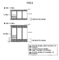
- FIG. 5 illustrates an exemplary RACH multiplexing method for the system bandwidth being wider than the minimum bandwidth.
- the RACH and signals other than the RACH are frequency-division multiplexed with each other in the same subframe.
- the bandwidth scheduled by a PUCCH unattached to a PUSCH may be variably adjusted depending on the number of users. Alternatively, different bandwidths may be applied for the PUCCH unattached to the PUSCH depending on the system bandwidth. It is not preferable to change mapping position of the RACH depending on the number of users or other factors from the viewpoint of reduction in control signaling. From this viewpoint, it is preferable to limit the mapping position of the RACH such that the RACH can be mapped into frequencies to which the PUCCH is not mapped at all. For example, the maximum bandwidth for mapping the PUCCH may be predefined for each system bandwidth, and the RACH may be mapped to the frequencies to which the PUCCH is not mapped at all.
- the same frequency for mapping the RACH may be maintained independent of subframes.
- frequencies to which the RACH may be mapped be variously hopped from the viewpoint of the frequency diversity effect.
- the RACH iteration period may be set to 40 ms including four radio frames including ten subframes of 1 ms.
- the RACH iteration period may be preferably set to a transmission period of the BCH, for example, 40 ms.
- the BCH or a DL-RS is transmitted at a predefined frequency, and different scramble codes are cyclically applied to the BCH and others. For this reason, the cycle of these different scramble codes may be matched with the RACH iteration period. In this manner, it is preferable that the RACH iteration period be matched with the BCH transmission period or the cycle of the scramble codes from the viewpoint of simple and accurate derivation of the RACH transmission timing.
- FIG. 7 illustrates that more frequencies for mapping the RACH are provided for wider system bandwidths.
- the same RACH transmission frequency is applied independent of the different system bandwidths.
- the RACH may be transmitted once five subframes.
- the RACH frequency has two options A, B in case of 5 MHz and four options A to D in case of 40 MHz. In this manner, it is preferable to make the RACH transmission frequency constant independent of the system bandwidths in order to make control information regarding the RACH multiplexing method as uniform over different cells as possible.
- the RACH can be transmitted at the same frequency in several cells (or in accordance with the same hopping pattern).
- FIG. 8 illustrates that mutually cyclically shifted hopping patterns are used in adjacent cells.
- RACHs may be mapped to frequencies ... , A, C, B, D, A, C, ... chronologically.
- the pattern in cell 1 starts with A and the pattern in cell 2 starts with D.
- cell 1 and cell 2 may be synchronized with each other, it is preferable to have the patterns mutually unsynchronized by design in order to prevent frequency conflict.
- FIG. 9 illustrates that different transmission frequencies of RACHs are applied in addition to frequency selection as illustrated in FIG. 7 .
- the term "transmission frequency" used herein means not frequency of actual transmissions but arrival frequency of resources to which the RACHs may be mapped. Thus, the RACHs may or may not be actually transmitted at that frequency.
- the transmission frequency is equal to twice per iteration period.
- the transmission frequency is equal to four times per iteration period.
- the transmission frequency is equal to eight times per iteration period.
- hopping patterns of the RACHs can be derived based on the system bandwidth and the transmission frequency.
- users can easily identify resources for transmitting the RACHs through transmissions of the system bandwidth and the transmission frequency in the BCH to the users.
- the RACH hopping patterns may be uniquely identified using not only the system bandwidth and the transmission frequency but also other control information, for example, one-bit control information.
- FIG. 10 is a block diagram illustrating a user apparatus according to one embodiment of the present invention.
- a RACH sequence generation unit 102 a transmission subframe control unit 104, a frequency shift unit 106 and a radio unit 108 are illustrated.
- the RACH sequence generation unit 102 generates information to be included in RACHs.
- the RACH sequence generation unit 102 generates necessary information items depending on the purpose of the RACHs such as initial access, resource assignment request and synchronization request.
- the transmission subframe control unit 104 identifies timing of subframes where the RACHs can be transmitted and associates the RACHs with these subframes.
- the subframes for transmitting the RACHs are determined based on BCHs.
- the BCHs include general information commonly available to a large number of users in a resident cell. According to the present invention, the BCHs particularly include information items such as system bandwidth for the resident cell, a cyclic shift amount and frequency.
- the frequency shift unit 106 maps the RACHs to the frequencies where the RACHS may be transmitted. These frequencies for transmitting the RACHs may be determined by identifying frequency hopping patterns or bands to which PUCCHs are mapped, for example. As stated above, such frequency hopping patterns may be derived based on information items such as the system bandwidth and the cyclic shift amount.
- the radio unit 108 performs signaling operations to transmit the RACHs as radio signals.
- FIG. 11 is a block diagram illustrating a base station apparatus according to one embodiment of the present invention.
- a RACH slot control unit 111 a BCH information generation unit 112, a radio unit 113, a FFT unit 114, a RACH resource identification unit 115 and a RACH detection unit 116 are illustrated.
- the RACH slot control unit 111 determines how user apparatuses residing within its own cell transmit RACHs. Specifically, the RACH slot control unit 111 identifies frequency and time resources where the RACHs may be transmitted. The determined contents may be fixed in the system or be variably controlled depending on situations.
- the RACH slot control unit 111 may determine some information items such as a hopping pattern of frequencies used for the RACHs, a cyclic shift amount of the hopping pattern and a frequency for allowing the RACHs to be transmitted. These information items may be derived in consideration of the system bandwidth, the number of accommodated users, hopping cell patterns of adjacent cells, maximum bandwidths of PUCCHs unattached to PUSCHs and others.
- the BCH information generation unit 112 includes the information items in the BCHs (such a the hopping pattern of RACH frequency resources, the cyclic shift amount of the hopping pattern and the frequency for allowing the RACHs to be transmitted) indicative of resources available for the RACHs.
- the BCHs include other general information items such as a cell ID.
- the radio unit 113 performs signal conversion between base band signals for use in the base station apparatus and radio signals for radio transmissions to user apparatuses.
- the FFT unit 114 performs Fourier transform on received signals for conversion into frequency domain signals. If a known mapping has been performed, the corresponding demapping is performed.
- the RACH resource identification unit 115 identifies resources where the RACHs may be transmitted.
- the resource position (time and frequency) is determined by the RACH slot control unit 111.
- the RACH detection unit 116 detects whether the RACHs are included in the resources identified by the RACH resource identification unit 115. If the RACHs are included, necessary control information for user apparatuses is transmitted depending on the purpose of the RACHs (such as initial access, resource assignment and synchronization).
Applications Claiming Priority (2)
| Application Number | Priority Date | Filing Date | Title |
|---|---|---|---|
| JP2007211594A JP5038060B2 (ja) | 2007-08-14 | 2007-08-14 | 移動通信システム、基地局装置、ユーザ装置及び方法 |
| PCT/JP2008/064487 WO2009022696A1 (ja) | 2007-08-14 | 2008-08-12 | 移動通信システム、基地局装置、ユーザ装置及び方法 |
Publications (1)
| Publication Number | Publication Date |
|---|---|
| EP2180730A1 true EP2180730A1 (en) | 2010-04-28 |
Family
ID=40350748
Family Applications (1)
| Application Number | Title | Priority Date | Filing Date |
|---|---|---|---|
| EP08792420A Withdrawn EP2180730A1 (en) | 2007-08-14 | 2008-08-12 | Mobile communication system, base station apparatus, user equipment and method |
Country Status (6)
| Country | Link |
|---|---|
| US (1) | US8311026B2 (ja) |
| EP (1) | EP2180730A1 (ja) |
| JP (1) | JP5038060B2 (ja) |
| KR (1) | KR20100050507A (ja) |
| CN (1) | CN101822117B (ja) |
| WO (1) | WO2009022696A1 (ja) |
Cited By (4)
| Publication number | Priority date | Publication date | Assignee | Title |
|---|---|---|---|---|
| WO2014005284A1 (en) | 2012-07-03 | 2014-01-09 | Nokia Corporation | Methods and apparatus for contention based transmission |
| US8797942B2 (en) | 2009-09-25 | 2014-08-05 | Telefonaktiebolaget Lm Ericsson (Publ) | Random access with full coverage on selected resources |
| CN110234129A (zh) * | 2019-06-12 | 2019-09-13 | 东北大学 | 一种NB-IoT网络中终端重传次数优化方法 |
| US10554366B2 (en) | 2015-07-27 | 2020-02-04 | Telefonaktiebolaget Lm Ericsson (Publ) | NB LTE PRACH design |
Families Citing this family (27)
| Publication number | Priority date | Publication date | Assignee | Title |
|---|---|---|---|---|
| DE102008011122A1 (de) * | 2008-02-26 | 2009-09-03 | Rohde & Schwarz Gmbh & Co. Kg | Verfahren und System zur Bandbreitendetektion |
| JP5138097B2 (ja) * | 2008-07-02 | 2013-02-06 | テレフオンアクチーボラゲット エル エム エリクソン(パブル) | 無線通信ネットワークにおいてrach構成を自動調整する方法および装置 |
| CN104523071A (zh) | 2008-07-18 | 2015-04-22 | 金瑟姆股份公司 | 气候受控床组件 |
| JP5574536B2 (ja) * | 2008-09-22 | 2014-08-20 | シャープ株式会社 | 無線通信システム、基地局装置、移動局装置および無線通信方法 |
| US8761059B2 (en) * | 2008-10-10 | 2014-06-24 | Lg Electronics Inc. | Method for transmitting relay node-specific control channel |
| KR101470063B1 (ko) | 2009-03-12 | 2014-12-12 | 인터디지탈 패튼 홀딩스, 인크 | 업링크 일차 반송파를 선택 및 재선택하는 방법 및 장치 |
| WO2012011775A2 (ko) * | 2010-07-22 | 2012-01-26 | 엘지전자 주식회사 | 다중 반송파 시스템에서 상향링크 제어 정보 전송 방법 및 장치 |
| CN103026649B (zh) | 2010-07-26 | 2017-04-12 | Lg电子株式会社 | 用于传输控制信息的方法和装置 |
| KR101285398B1 (ko) | 2010-09-08 | 2013-07-10 | 엘지전자 주식회사 | 무선 통신 시스템에서 제어 정보의 전송 방법 및 장치 |
| US8670410B2 (en) * | 2010-09-17 | 2014-03-11 | Qualcomm Incorporated | Uplink control channel resource mapping for carrier aggregation |
| CN105846963B (zh) * | 2010-11-02 | 2020-01-14 | Lg电子株式会社 | 在无线通信系统中发射/接收上行链路控制信息的方法和装置 |
| JP5832545B2 (ja) | 2010-11-02 | 2015-12-16 | エルジー エレクトロニクス インコーポレイティド | 無線通信システムにおいて上りリンク制御情報の送受信方法及び装置 |
| CN106059717B (zh) | 2010-12-02 | 2019-08-09 | Lg电子株式会社 | 在基于时分双工的无线通信系统中发送ack/nack的方法和装置 |
| KR20120082711A (ko) * | 2011-01-14 | 2012-07-24 | 주식회사 팬택 | 이종 통신 시스템에서의 위치 참조 신호 송수신 장치 및 방법 |
| KR20120093026A (ko) * | 2011-02-14 | 2012-08-22 | 주식회사 팬택 | 무선통신 시스템에서의 참조신호 할당방법과 할당장치, 및 그를 이용한 참조신호 수신방법과 장치 |
| JP5693996B2 (ja) * | 2011-02-23 | 2015-04-01 | 株式会社Nttドコモ | 無線基地局、ユーザ端末及び周波数帯域共用方法 |
| US9232540B2 (en) | 2011-09-30 | 2016-01-05 | Qualcomm Incorporated | Random access channel design for narrow bandwidth operation in a wide bandwidth system |
| CN102790665A (zh) * | 2012-03-13 | 2012-11-21 | 中兴通讯股份有限公司 | Ack/nack信息的发送系统、发送方法及资源配置方法和基站 |
| BR112015009217A2 (pt) | 2012-11-01 | 2017-07-04 | Sony Corp | dispositivo e método de controle de comunicação, programa, e, dispositivo terminal |
| US20140169325A1 (en) * | 2012-12-14 | 2014-06-19 | Nokia Siemens Networks Oy | Carrier deployment method for reduced bandwidth mtc devices |
| US9392622B2 (en) * | 2013-05-14 | 2016-07-12 | Telefonaktiebolaget Lm Ericsson (Publ) | System and method for configuring a radio access network |
| KR101689846B1 (ko) * | 2015-07-14 | 2016-12-26 | 콘텔라 주식회사 | 트래픽 추이를 검출할 수 있는 분산안테나시스템 및 그 트래픽 분석 방법 |
| KR20170033198A (ko) * | 2015-09-16 | 2017-03-24 | 삼성전자주식회사 | 디스플레이 장치 및 디스플레이 장치의 제어 장치 |
| ES2924363T3 (es) * | 2015-12-08 | 2022-10-06 | Huawei Tech Co Ltd | Método para enviar datos, estación base y dispositivo terminal |
| US10334633B2 (en) * | 2016-01-07 | 2019-06-25 | Qualcomm Incorporated | Narrow band physical random access channel frequency hopping patterns and detection schemes |
| DE102016220883A1 (de) | 2016-10-24 | 2018-04-26 | Fraunhofer-Gesellschaft zur Förderung der angewandten Forschung e.V. | Optimierte Kombination aus Präambel und Datenfeldern für Sensornetzwerke mit geringem Stromverbrauch auf Basis des Telegram Splitting Verfahrens |
| DE102016220882A1 (de) * | 2016-10-24 | 2018-04-26 | Fraunhofer-Gesellschaft zur Förderung der angewandten Forschung e.V. | Optimierte Sprungmuster für verschiedene Sensorknoten und variable Datenlängen auf Basis des Telegram Splitting Übertragungsverfahrens |
Family Cites Families (7)
| Publication number | Priority date | Publication date | Assignee | Title |
|---|---|---|---|---|
| SE515752C2 (sv) * | 1995-08-28 | 2001-10-08 | Telia Ab | Direktåtkomst i OFDM-system |
| CN1549610A (zh) * | 2003-05-09 | 2004-11-24 | 北京三星通信技术研究有限公司 | 在公共接入信道中提供多级接入服务的方法 |
| EP1949566B1 (en) * | 2005-11-04 | 2014-04-30 | LG Electronics Inc. | Random access channel hopping for frequency division multiplexing access systems |
| US8687564B2 (en) * | 2005-11-04 | 2014-04-01 | Lg Electronics Inc. | Random access dimensioning methods and procedures for frequency division multiplexing access systems |
| AR060989A1 (es) * | 2006-05-09 | 2008-07-30 | Interdigital Tech Corp | Canal de acceso aleatorio (rach) para un sistema ofdm-mimo |
| KR20090113377A (ko) * | 2007-02-28 | 2009-10-30 | 가부시키가이샤 엔티티 도코모 | 기지국장치 및 통신제어방법 |
| JP5283423B2 (ja) * | 2008-05-02 | 2013-09-04 | 株式会社エヌ・ティ・ティ・ドコモ | 移動通信システムにおける基地局装置、ユーザ装置及び方法 |
-
2007
- 2007-08-14 JP JP2007211594A patent/JP5038060B2/ja not_active Expired - Fee Related
-
2008
- 2008-08-12 US US12/672,522 patent/US8311026B2/en not_active Expired - Fee Related
- 2008-08-12 EP EP08792420A patent/EP2180730A1/en not_active Withdrawn
- 2008-08-12 CN CN2008801108637A patent/CN101822117B/zh not_active Expired - Fee Related
- 2008-08-12 WO PCT/JP2008/064487 patent/WO2009022696A1/ja active Application Filing
- 2008-08-12 KR KR1020107003379A patent/KR20100050507A/ko not_active Application Discontinuation
Non-Patent Citations (1)
| Title |
|---|
| See references of WO2009022696A1 * |
Cited By (8)
| Publication number | Priority date | Publication date | Assignee | Title |
|---|---|---|---|---|
| US8797942B2 (en) | 2009-09-25 | 2014-08-05 | Telefonaktiebolaget Lm Ericsson (Publ) | Random access with full coverage on selected resources |
| WO2014005284A1 (en) | 2012-07-03 | 2014-01-09 | Nokia Corporation | Methods and apparatus for contention based transmission |
| EP2870815A4 (en) * | 2012-07-03 | 2016-06-22 | Nokia Technologies Oy | METHOD AND DEVICE FOR COMPETITION-BASED TRANSMISSION |
| US10554366B2 (en) | 2015-07-27 | 2020-02-04 | Telefonaktiebolaget Lm Ericsson (Publ) | NB LTE PRACH design |
| US11108525B2 (en) | 2015-07-27 | 2021-08-31 | Telefonaktiebolaget Lm Ericsson (Publ) | NB LTE PRACH design |
| US11757595B2 (en) | 2015-07-27 | 2023-09-12 | Telefonaktiebolaget Lm Ericsson (Publ) | NB LTE PRACH design |
| CN110234129A (zh) * | 2019-06-12 | 2019-09-13 | 东北大学 | 一种NB-IoT网络中终端重传次数优化方法 |
| CN110234129B (zh) * | 2019-06-12 | 2021-08-17 | 东北大学 | 一种NB-IoT网络中终端重传次数优化方法 |
Also Published As
| Publication number | Publication date |
|---|---|
| WO2009022696A1 (ja) | 2009-02-19 |
| KR20100050507A (ko) | 2010-05-13 |
| US20120002613A1 (en) | 2012-01-05 |
| JP5038060B2 (ja) | 2012-10-03 |
| CN101822117A (zh) | 2010-09-01 |
| US8311026B2 (en) | 2012-11-13 |
| CN101822117B (zh) | 2013-05-22 |
| JP2009049538A (ja) | 2009-03-05 |
Similar Documents
| Publication | Publication Date | Title |
|---|---|---|
| US8311026B2 (en) | Mobile communication system, base station apparatus, user apparatus and method | |
| US11558893B2 (en) | Low latency physical uplink control channel with scheduling request and channel state information | |
| US10728077B2 (en) | Method and apparatus for performing random access procedure in NB-IoT carrier in wireless communication system | |
| US9854569B2 (en) | Uplink control channel configuration for unlicensed carriers | |
| US11729826B2 (en) | Multiple starting and ending positions for scheduled or autonomous uplink transmission in unlicensed spectrum | |
| US9876617B2 (en) | Wireless communication system, base station apparatus, mobile station apparatus, wireless communication method and integrated circuit | |
| CN108199818B (zh) | 用于在无线通信系统中映射控制信息的方法及设备 | |
| EP3316644B1 (en) | Transmission device, receiving device and method for uplink data | |
| EP3536082B1 (en) | Semi-persistent scheduling in sub-subframe operation | |
| US20220104126A1 (en) | Method and apparatus for power saving in sidelink communication | |
| US20160242039A1 (en) | Methods, Computer Programs, Network Nodes and Communication Device | |
| KR20210137214A (ko) | 비면허 대역에서 전송을 수행하기 위한 자원할당 방법 및 이를 이용하는 장치 | |
| KR20210096275A (ko) | 비면허 대역에서 전송을 수행하기 위한 채널 액세스 방법 및 이를 이용하는 장치 | |
| CN114175699B (zh) | 在支持机器类型通信的无线通信系统中发送和接收紧急信息的方法及其装置 | |
| KR20170093371A (ko) | 비면허 대역을 지원하는 무선 통신 시스템에서 상향링크 예약 신호 전송 방법 및 장치 | |
| KR20200099973A (ko) | 통신 시스템에서 이동성 지원을 위한 측정 방법 및 장치 | |
| KR20200100001A (ko) | 통신 시스템에서 이동성 지원을 위한 측정 방법 및 장치 |
Legal Events
| Date | Code | Title | Description |
|---|---|---|---|
| PUAI | Public reference made under article 153(3) epc to a published international application that has entered the european phase |
Free format text: ORIGINAL CODE: 0009012 |
|
| 17P | Request for examination filed |
Effective date: 20100218 |
|
| AK | Designated contracting states |
Kind code of ref document: A1 Designated state(s): AT BE BG CH CY CZ DE DK EE ES FI FR GB GR HR HU IE IS IT LI LT LU LV MC MT NL NO PL PT RO SE SI SK TR |
|
| AX | Request for extension of the european patent |
Extension state: AL BA MK RS |
|
| DAX | Request for extension of the european patent (deleted) | ||
| STAA | Information on the status of an ep patent application or granted ep patent |
Free format text: STATUS: THE APPLICATION HAS BEEN WITHDRAWN |
|
| 18W | Application withdrawn |
Effective date: 20150709 |