EP2180589A2 - Verfahren zur Vorhersage von Phasenstrom - Google Patents
Verfahren zur Vorhersage von Phasenstrom Download PDFInfo
- Publication number
- EP2180589A2 EP2180589A2 EP09171623A EP09171623A EP2180589A2 EP 2180589 A2 EP2180589 A2 EP 2180589A2 EP 09171623 A EP09171623 A EP 09171623A EP 09171623 A EP09171623 A EP 09171623A EP 2180589 A2 EP2180589 A2 EP 2180589A2
- Authority
- EP
- European Patent Office
- Prior art keywords
- current
- phase
- measured
- link
- voltage vector
- Prior art date
- Legal status (The legal status is an assumption and is not a legal conclusion. Google has not performed a legal analysis and makes no representation as to the accuracy of the status listed.)
- Withdrawn
Links
Images


Classifications
-
- H—ELECTRICITY
- H02—GENERATION; CONVERSION OR DISTRIBUTION OF ELECTRIC POWER
- H02M—APPARATUS FOR CONVERSION BETWEEN AC AND AC, BETWEEN AC AND DC, OR BETWEEN DC AND DC, AND FOR USE WITH MAINS OR SIMILAR POWER SUPPLY SYSTEMS; CONVERSION OF DC OR AC INPUT POWER INTO SURGE OUTPUT POWER; CONTROL OR REGULATION THEREOF
- H02M7/00—Conversion of AC power input into DC power output; Conversion of DC power input into AC power output
- H02M7/42—Conversion of DC power input into AC power output without possibility of reversal
- H02M7/44—Conversion of DC power input into AC power output without possibility of reversal by static converters
- H02M7/48—Conversion of DC power input into AC power output without possibility of reversal by static converters using discharge tubes with control electrode or semiconductor devices with control electrode
- H02M7/53—Conversion of DC power input into AC power output without possibility of reversal by static converters using discharge tubes with control electrode or semiconductor devices with control electrode using devices of a triode or transistor type requiring continuous application of a control signal
- H02M7/537—Conversion of DC power input into AC power output without possibility of reversal by static converters using discharge tubes with control electrode or semiconductor devices with control electrode using devices of a triode or transistor type requiring continuous application of a control signal using semiconductor devices only, e.g. single switched pulse inverters
- H02M7/5387—Conversion of DC power input into AC power output without possibility of reversal by static converters using discharge tubes with control electrode or semiconductor devices with control electrode using devices of a triode or transistor type requiring continuous application of a control signal using semiconductor devices only, e.g. single switched pulse inverters in a bridge configuration
- H02M7/53871—Conversion of DC power input into AC power output without possibility of reversal by static converters using discharge tubes with control electrode or semiconductor devices with control electrode using devices of a triode or transistor type requiring continuous application of a control signal using semiconductor devices only, e.g. single switched pulse inverters in a bridge configuration with automatic control of output voltage or current
- H02M7/53875—Conversion of DC power input into AC power output without possibility of reversal by static converters using discharge tubes with control electrode or semiconductor devices with control electrode using devices of a triode or transistor type requiring continuous application of a control signal using semiconductor devices only, e.g. single switched pulse inverters in a bridge configuration with automatic control of output voltage or current with analogue control of three-phase output
-
- G—PHYSICS
- G01—MEASURING; TESTING
- G01R—MEASURING ELECTRIC VARIABLES; MEASURING MAGNETIC VARIABLES
- G01R19/00—Arrangements for measuring currents or voltages or for indicating presence or sign thereof
- G01R19/145—Indicating the presence of current or voltage
- G01R19/15—Indicating the presence of current
-
- G—PHYSICS
- G01—MEASURING; TESTING
- G01R—MEASURING ELECTRIC VARIABLES; MEASURING MAGNETIC VARIABLES
- G01R19/00—Arrangements for measuring currents or voltages or for indicating presence or sign thereof
- G01R19/14—Indicating direction of current; Indicating polarity of voltage
-
- G—PHYSICS
- G01—MEASURING; TESTING
- G01R—MEASURING ELECTRIC VARIABLES; MEASURING MAGNETIC VARIABLES
- G01R21/00—Arrangements for measuring electric power or power factor
- G01R21/06—Arrangements for measuring electric power or power factor by measuring current and voltage
-
- H—ELECTRICITY
- H02—GENERATION; CONVERSION OR DISTRIBUTION OF ELECTRIC POWER
- H02M—APPARATUS FOR CONVERSION BETWEEN AC AND AC, BETWEEN AC AND DC, OR BETWEEN DC AND DC, AND FOR USE WITH MAINS OR SIMILAR POWER SUPPLY SYSTEMS; CONVERSION OF DC OR AC INPUT POWER INTO SURGE OUTPUT POWER; CONTROL OR REGULATION THEREOF
- H02M1/00—Details of apparatus for conversion
- H02M1/0003—Details of control, feedback or regulation circuits
- H02M1/0009—Devices or circuits for detecting current in a converter
Definitions
- the present invention relates to a phase current prediction methods, and more particularly to methods to measure DC link current of an inverter through a single current sensor provided between the inverter, which drives a motor, and a DC voltage source to predict phase current of the motor.
- an inverter circuit is a power conversion device that converts direct current (DC) power into pulse-shaped 3-phase (U, V and W) alternating current (AC) power having a variable frequency. Due to reduction in energy consumption and easiness of output control, the inverter circuit has been increasingly used to drive motors used in electric products such as a washing machine, refrigerator, and air conditioner.
- sampling-based average current is used, whereas current actually flowing to the motor continuously varies, and is not fixed, as shown in FIG. 1 .
- carrier start or middle values i a m , i b m and i c m which are control representative values indicative of average current in a PWM period, are measured for control of a motor, the measured values are determined to be phase currents, and currents to be applied to the motor are controlled based on the determined phase currents.
- phase current prediction method to predict current representative of a PWM period using DC link current measured through a single current sensor and determine the predicted current to be phase current, thereby reducing a current error and, thus, a current ripple.
- phase current prediction method including sequentially applying an effective voltage vector to an inverter, measuring DC link current in a period in which the effective voltage vector is applied, and predicting three phase currents representative of a PWM period of the inverter using the measured DC link current.
- phase current prediction method including sequentially applying a first effective voltage vector and a second effective voltage vector to an inverter, measuring first DC link current during a period in which the first effective voltage vector is applied, measuring second DC link current during a period in which the second effective voltage vector is applied, predicting phase current using the first DC link current before the measuring the second DC link current, and predicting three phase currents using the measured second DC link current and the predicted phase current after the measuring the second DC link current, and predicting the three phase currents for a PWM period using the predicted three phase currents.
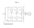
- FIG. 2 shows the configuration of a 3-phase PWM inverter system using a single current sensor, to which an embodiment of the present invention is applied.
- a 3-phase motor M which is an AC motor, includes a stator including resistors and inductors, and an internal rotor.
- the 3-phase motor M has phase terminals connected to an inverter 1. When phase currents flow to the inductors respectively through the phase terminals, a magnetic field is formed, so as to rotate the internal rotor.
- the inverter 1 functions to convert a DC voltage into a pulse-shaped 3-phase AC voltage having a variable frequency through pulse width modulation (PWM) to drive the motor.
- PWM pulse width modulation
- the inverter 1 has six switching elements Q1 to Q6 for switching, which are paired in series and connected respectively to the phase terminals of the 3-phase motor M.
- the upper switching elements Q1, Q3 and Q5 are connected to a positive terminal of a DC voltage source Vdc and the lower switching elements Q2, Q4 and Q6 are connected to a negative terminal of the DC voltage source Vdc.
- This inverter 1 is driven by an SVPWM signal pattern.
- the single current sensor is provided between the inverter 1 and the DC voltage source Vdc to measure current flowing to a DC link side of the inverter 1.
- the operation of the 3-phase PWM inverter system with the above-stated configuration will hereinafter be described.
- the six switching elements Q1 to Q6 of the inverter 1 are on/off-controlled in such a manner that any one of the upper switching elements Q1, Q3 and Q5 is turned on and any one of the lower switching elements Q2, Q4 and Q6 corresponding to a phase different from a phase corresponding to the turned-on upper switching element is turned on. Also, while the switching elements Q1 to Q6 of the inverter 1 are switched, phase current of the motor M is predicted based on DC link current measured by the single current sensor 2 and the switching elements Q1 to Q6 of the inverter 1 are selectively switched based on the predicted phase current.
- the switching elements Q1 to Q6 of the inverter 1 are controlled in pairs in such a manner that, when any one switching element of each pair is turned on, the other switching element is turned off.
- the upper switching elements Q1, Q3 and Q5 each have a 1 or 0 state to indicate the entire switching state of the inverter 1.
- the 1 state means that a switch is closed to conduct
- the 0 state means that a switch is open.
- An SVPWM scheme is a scheme that generates SVPWM signals using eight fundamental voltage vectors corresponding respectively to the eight states.
- DC link current detected by the single current sensor 2 in a period in which each fundamental voltage vector is applied corresponds to any one of three phase currents flowing to the motor M.
- FIG. 3 is a table illustrating fundamental voltage vectors and corresponding phase currents predictable using a single current sensor, in an embodiment of the present invention.
- the fundamental voltage vectors include six effective voltage vectors V1 to V6, and two zero voltage vectors V7 and V8, which are, respectively, (1, 1, 1) and (0, 0, 0) indicating a state where no current flows to the motor M because all the upper or lower switching elements are turned off.
- the numerals in parentheses indicate on/off states of the switching elements Q1, Q3 and Q5, respectively.
- the six effective voltage vectors V1 to V6, among the fundamental voltage vectors are arranged to be 60 degrees out of phase with each other, and the zero voltage vectors V7 and V8 are positioned at the origin of the effective voltage vectors V1 to V6.
- SVPWM signals are generated such that fundamental voltage vectors V1 to V8 into which the command voltage vector is decomposed are applied.
- SVPWM signals are generated for control of the operation of the inverter based on a command voltage vector in a PWM period Tpwm.
- Sa, Sb and Sc may be SVPWM signals for control of the switching elements Q1, Q3 and Q5, respectively.
- the fundamental voltage vectors are applied to the motor M in the order of V8, V1, V2, V7, V2, V1 and V8. An application time of each fundamental voltage vector is shown in FIG. 4 .
- DC link current may be measured through the single current sensor 2 in a period in which each effective voltage vector, among the fundamental voltage vectors, is applied, currents of two different phases may be predicted from the measured DC link current, and current of the remaining one phase may then be predicted using the fact that the sum of three phase currents is 0.
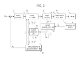
- FIG. 5 shows the configuration of a motor drive system to which a phase current prediction apparatus according to an embodiment of the present invention is applied.
- the motor drive system includes a speed controller 10, current controller 20, vector regulator 30, space vector modulator 40, current reconstruction unit 50, current prediction unit 70, and rotor position and speed estimation unit 60, in addition to the inverter 1 and single current sensor 2.
- the speed controller 10 receives a speed command and an estimated speed and outputs a torque command.
- the current controller 20 receives the torque command and three phase currents predicted by the current prediction unit 70 and applies a reference voltage vector v based on the received torque command and three phase currents to the vector regulator 30.
- the vector regulator 30 performs no modulation and compensation for the reference voltage vector v when the reference voltage vector v is present in an effective area of a space vector domain.
- the vector regulator 30 performs modulation and compensation for the reference voltage vector v to deviate the reference voltage vector v from the ineffective area to the effective area and outputs the resulting modulated and compensated voltage vectors vm and vc to the space vector modulator 40.
- the space vector modulator 40 receives the reference voltage vector regulated by the vector regulator 30 and applies a phase voltage corresponding to a switching pattern to switch of the respective switching elements of the inverter 1 to the inverter 1.
- the inverter 1 on/off-controls the respective switching elements in response to the phase voltage corresponding to the switching pattern to apply three phase currents to the motor M.
- the current reconstruction unit 50 reconstructs phase current using DC link current measured by the single current sensor 2 installed at the DC link side of the inverter 1 and the switching pattern for the respective switching elements of the inverter 1.
- the current reconstruction unit 50 provides the reconstructed phase current and the modulated and compensated voltage vectors vm and vc provided by the vector regulator 30 to the current prediction unit 70.
- the rotor position and speed estimation unit 60 estimates the position and speed of the rotor of the motor M based on three phase currents predicted by the current prediction unit 70.
- the rotor position and speed estimation unit 60 provides the estimated rotor position and speed to the current prediction unit 70.
- the current prediction unit 70 predicts three phase currents based on the reconstructed phase current and the modulated and compensated voltage vectors vm and vc from the current reconstruction unit 50 and the estimated rotor position and speed from the rotor position and speed estimation unit 60.
- the predicted three phase currents are provided to the current controller 20 for current control of the motor M or to the rotor position and speed estimation unit 60 for control of the position and speed of the rotor of the motor M.
- the current prediction unit 70 predicts each phase current from a voltage, current, estimated flux angle and estimated speed as in the following equation 3.
- i ⁇ abc m f i abc s ⁇ v m ⁇ v c ⁇ ⁇ ⁇ r ⁇ ⁇ ⁇ r
- This prediction aims at making the predicted current be a representative value of one PWM period as in the following equation 4. i ⁇ abc m ⁇ i abc m
- the predicted current may be applied to a sensorless control, as shown in FIG. 5 .
- the predicted three phase currents are utilized for the current control of the motor M or the rotor position and speed estimation.
- the motor M is a surface mounted permanent magnet motor.
- v d r is a d-axis voltage on a rotor coordinate system
- v q r is a q-axis voltage on the rotor coordinate system
- i d r is d-axis current on the rotor coordinate system
- i q r q-axis current on the rotor coordinate system
- ⁇ r is an angular velocity
- R s is a stator winding resistance
- L s is a stator inductance
- K e is a motor
- a voltage vector of a rotating coordinate system may be expressed as follows.
- v r R s ⁇ i r + p ⁇ ⁇ r + ⁇ r ⁇ J ⁇ r
- v r v d r v q r
- i r i d r i q r
- ⁇ r L s ⁇ i d r + K e L s ⁇ i q r
- J 0 - 1 1 0 .
- the above equation 6 may be expressed in the form of a state equation as follows.
- i ⁇ r A r ⁇ i r + B r ⁇ 0 ⁇ v r + B r ⁇ 1
- a r 1 L s ⁇ - R s ⁇ r ⁇ L s - ⁇ r ⁇ L s - R s
- B r ⁇ 0 1 L s ⁇ I
- B r ⁇ 1 1 L s ⁇ 0 - ⁇ s ⁇ K s
- I 1 0 0 1 .
- L r is a gain matrix for prediction.
- a voltage vector of a coordinate system at rest may be expressed as follows.
- v s v d s v q s
- i s i d s i q s
- T ⁇ r cos ⁇ r sin ⁇ r - sin ⁇ r cos ⁇ r
- ⁇ s L e ⁇ i s + T ⁇ - ⁇ y ⁇ K e 0 .
- a phase current-based predictor is introduced in order to solve this problem.
- i ⁇ ⁇ c - R s L s - L c ⁇ i ⁇ c + L c ⁇ i c + 1 L s ⁇ v c + ⁇ s ⁇ L e L s ⁇ sin ⁇ r - 2 ⁇ ⁇ 3
- FIG. 6 illustrates a phase current prediction concept of a phase current prediction apparatus according to an embodiment of the present invention.
- phase current is predicted separately at the plurality of operations. For example, when an output voltage is present in a sector 1 (1, 0, 0) among eight sectors V1 to V8, phase current is sampled at Ta and Tc, whereas current representative of one PWM period is sampled at Ts.
- values measured at Ta and Tc are predicted to approximate values to be measured at Ts as much as possible, so that a current error may be reduced to improve performance of the motor.
- FIG. 7 illustrates a phase current prediction method according to one embodiment of the present invention
- FIG. 8 illustrates prediction of three phase currents according to this embodiment.
- the prediction starts with Ta and then proceeds to Ts via T2, Tc, T3, T4, T5, T6 and T7.
- a first effective voltage vector V1 (1, 0, 0) is applied to the inverter 1 (100), and the output value of the single current sensor 2 is then read for measurement of a first DC link current Idc_1 (101).
- the first DC link current idc_1 is phase current i a s of phase A.
- phase current i ⁇ a 2 is predicted (102). At this time, the phase current i ⁇ a 2 may be obtained by applying the first DC link current i a s to equation 16 and then integrating equation 16.
- phase current i ⁇ a 2 is predicted
- phase current i ⁇ a c is predicted (103).
- the phase current i ⁇ a c may be obtained by applying the phase current i ⁇ a 2 to equation 16 and then integrating equation 16.
- a second effective voltage vector V2 (1, 1, 0) is applied to the inverter 1 (104), and the output value of the single current sensor 2 is then read for measurement of a second DC link current idc_2 (105).
- the second DC link current idc_2 is phase current i c s of phase C.
- phase currents i ⁇ a 3 and i ⁇ c 3 are predicted (106).
- the phase currents i ⁇ a 3 and i ⁇ c 3 may be obtained by applying the above- predicted i ⁇ a c and the second DC link current i c s to equation 12 and then integrating equation 12.
- phase currents i ⁇ a 3 and i ⁇ c 3 are predicted, phase currents i ⁇ a 5 and i ⁇ c 5 are predicted (107).
- phase currents i ⁇ a 5 and i ⁇ c 5 may be obtained by applying the phase currents i ⁇ a 3 and i ⁇ c 3 to equation 12 and then integrating equation 12.
- phase currents i ⁇ a 5 and i ⁇ c 5 are predicted, phase currents i ⁇ a 6 and i ⁇ c 6 are predicted (108).
- phase currents i ⁇ a 6 and i ⁇ c 6 may be obtained by applying the phase currents i ⁇ a 5 and i ⁇ c 5 to equation 12 and then integrating equation 12.
- phase currents i ⁇ a 6 and i ⁇ c 6 are predicted, phase currents i ⁇ a 7 and i ⁇ c 7 are predicted (109).
- phase currents i ⁇ a 7 and i ⁇ c 7 may be obtained by applying the phase currents i ⁇ a 6 and i ⁇ c 6 to equation 12 and then integrating equation 12.
- phase currents i ⁇ a 7 and i ⁇ c 7 are predicted, three phase currents i ⁇ a m , i ⁇ c m and i ⁇ b m representative of a PWM period are finally predicted (110).
- the three phase currents i ⁇ a m , i ⁇ c m and i ⁇ b m representative of the PWM period may be predicted using the DC link currents i a s and i c s measured respectively in the effective voltage vector periods, thereby making it possible to reduce a current error and, thus, a current ripple.
- phase current of phase A is predicted using the equation 16. This prediction is carried out in the Ta to Tc period of FIG. 8 .
- three phase currents are predicted by obtaining two phase currents, converting the obtained two phase currents into d-axis current and q-axis current, respectively, and applying the converted d-axis current and q-axis current to equation 12. This prediction is carried out in the Tc to Ts period of FIG. 8 .
- the three phase currents i ⁇ a m , i ⁇ b m and i ⁇ c m representative of the PWM period are predicted from the DC link currents i a s and i c s measured by the single current sensor 2.
- the predicted three phase currents i ⁇ a m , i ⁇ b m and i ⁇ c m are utilized for motor current control or motor rotor position and speed control.
- the three phase currents i ⁇ a m , i ⁇ b m and i ⁇ c m may be predicted in a similar method to the above-stated method.
- the current prediction steps include seven steps as stated above.
- the sampling of the single current sensor 2 is carried out at the last portion of an effective voltage vector, namely, the last time point of an effective voltage vector period, Ta will be the same as T2, and Tc will be the same as T3.
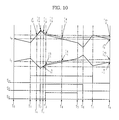
- OPERATION 1 and OPERATION 3 may be removed as shown in FIG. 9 , so that the current prediction operations may be compressed from seven steps to five steps.
- FIG. 9 illustrates current prediction operations resulting from removal of OPERATION 1 and OPERATION 3 from the current prediction operations of FIG. 8 .
- FIG. 10 illustrates current prediction operations resulting from compression of STEP 4 and STEP 7 of FIG. 8 to one operation.
- step-unit current prediction is performed in the Ta to T4 period, and the average effective voltage vector-based current prediction is performed in the second half of the PWM period.
- Ta will be the same as T2
- Tc will be the same as T3.
- OPERATION 1 and OPERATION 3 in the step-unit current prediction may be omitted as shown in FIG. 11 , so that the entire current prediction may include three steps.
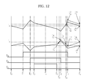
- the current prediction may not be performed in the first half of the PWM period and may be performed in the second half of the PWM period.
- the DC link current measurement is made in the second half of the PWM period, so that the current prediction operations may be compressed.
- the DC link current sampling is carried out as shown in FIG. 12 , and the current prediction operations are as follows.
- Tc will be the same as T6, and Ta will be the same as T7.
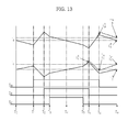
- OPERATION 1 and OPERATION 3 may be omitted in the above four current prediction operations as shown in FIG. 13 , so that the current prediction may include of two steps.
- a phase current prediction method predicts current representative of a PWM period using a motor model which receives current measured through a single current sensor as an input, instead of the measured current, and determines the predicted current to be phase current, thereby reducing a current error and, thus, a current ripple. Furthermore, it may be possible to not only reduce motor noise, but also improve control capability.
Landscapes
- Engineering & Computer Science (AREA)
- Power Engineering (AREA)
- Physics & Mathematics (AREA)
- General Physics & Mathematics (AREA)
- Control Of Ac Motors In General (AREA)
- Inverter Devices (AREA)
- Control Of Electric Motors In General (AREA)
Applications Claiming Priority (1)
| Application Number | Priority Date | Filing Date | Title |
|---|---|---|---|
| KR1020080097420A KR101517101B1 (ko) | 2008-10-02 | 2008-10-02 | 상전류 추정방법 |
Publications (2)
| Publication Number | Publication Date |
|---|---|
| EP2180589A2 true EP2180589A2 (de) | 2010-04-28 |
| EP2180589A3 EP2180589A3 (de) | 2018-02-07 |
Family
ID=41718712
Family Applications (1)
| Application Number | Title | Priority Date | Filing Date |
|---|---|---|---|
| EP09171623.3A Withdrawn EP2180589A3 (de) | 2008-10-02 | 2009-09-29 | Verfahren zur Vorhersage von Phasenstrom |
Country Status (3)
| Country | Link |
|---|---|
| US (1) | US8362759B2 (de) |
| EP (1) | EP2180589A3 (de) |
| KR (1) | KR101517101B1 (de) |
Families Citing this family (31)
| Publication number | Priority date | Publication date | Assignee | Title |
|---|---|---|---|---|
| US8248829B2 (en) * | 2009-05-01 | 2012-08-21 | Board Of Regents, The University Of Texas System | Methods and systems for phase current reconstruction of AC drive systems |
| JP5182302B2 (ja) * | 2010-02-08 | 2013-04-17 | 株式会社デンソー | 回転機の制御装置 |
| US9274149B2 (en) * | 2012-04-16 | 2016-03-01 | Hamilton Sundstrand Corporation | Frequency phase detection three phase system |
| JP5886117B2 (ja) * | 2012-04-22 | 2016-03-16 | 株式会社デンソー | 交流電動機の制御装置 |
| JP5533928B2 (ja) * | 2012-04-22 | 2014-06-25 | 株式会社デンソー | 交流電動機の制御装置 |
| JP5541587B2 (ja) * | 2012-04-22 | 2014-07-09 | 株式会社デンソー | 交流電動機の制御装置 |
| JP5527559B2 (ja) * | 2012-04-22 | 2014-06-18 | 株式会社デンソー | 交流電動機の制御装置 |
| JP5370625B1 (ja) * | 2012-05-15 | 2013-12-18 | パナソニック株式会社 | モータ制御システム、モータ制御装置およびブラシレスモータ |
| US8901869B2 (en) * | 2012-07-31 | 2014-12-02 | Caterpillar Inc. | Hybrid closed loop speed control using open look position for electrical machines controls |
| WO2014049694A1 (ja) * | 2012-09-25 | 2014-04-03 | 株式会社安川電機 | モータ制御装置 |
| JP6040689B2 (ja) * | 2012-09-28 | 2016-12-07 | 富士電機株式会社 | 交流電動機の制御装置 |
| CN103840725B (zh) * | 2012-11-26 | 2016-05-18 | 台达电子工业股份有限公司 | 永磁同步电机转子位置偏差测量装置及方法 |
| KR101769649B1 (ko) * | 2013-09-02 | 2017-08-18 | 엘에스산전 주식회사 | 인버터 시스템에서 전력 케이블의 상태 검출 방법 |
| US20150102758A1 (en) * | 2013-10-15 | 2015-04-16 | Samsung Electro-Mechanics Co., Ltd. | Motor drive controller, motor drive control method and motor system using the same |
| KR101583951B1 (ko) * | 2014-07-02 | 2016-01-08 | 현대자동차주식회사 | 친환경 차량용 인버터의 전압이용율 향상 제어 장치 및 방법 |
| US9225264B1 (en) | 2014-08-26 | 2015-12-29 | Texas Instruments Incorporated | Method and apparatus for multiphase inverter control |
| CN104242774B (zh) * | 2014-09-17 | 2016-11-30 | 中国第一汽车股份有限公司 | 一种电机相电流预测与诊断方法 |
| JP6515532B2 (ja) * | 2014-12-26 | 2019-05-22 | ダイキン工業株式会社 | 電力変換装置 |
| KR101996838B1 (ko) * | 2015-05-26 | 2019-07-08 | 엘에스산전 주식회사 | 유도 전동기 제어 시스템 |
| KR101698775B1 (ko) * | 2015-08-11 | 2017-01-23 | 엘지전자 주식회사 | 홈 어플라이언스 |
| US10581274B2 (en) | 2015-06-03 | 2020-03-03 | Lg Electronics Inc. | Home appliance |
| CN105141200B (zh) * | 2015-08-04 | 2019-04-09 | 矽力杰半导体技术(杭州)有限公司 | 一种永磁同步电机的驱动电路及驱动方法 |
| KR101663520B1 (ko) * | 2015-08-11 | 2016-10-07 | 엘지전자 주식회사 | 모터 구동장치 및 이를 구비하는 홈 어플라이언스 |
| CN106915124B (zh) * | 2015-12-24 | 2020-05-26 | 联想(北京)有限公司 | 一种保护层、电子设备及制作方法 |
| US10530285B1 (en) | 2018-11-05 | 2020-01-07 | Hamiton Sundstrand Corporation | Method and motor controller for measuring magnitude of varying non-sinusoidal voltages and currents of a motor controller |
| CN110488192B (zh) * | 2019-09-12 | 2022-01-14 | 哈尔滨工业大学 | 永磁同步电机驱动系统的三相电流重构方法 |
| DE102021101884B4 (de) | 2021-01-28 | 2022-10-06 | Schaeffler Technologies AG & Co. KG | Verfahren zur Phasenstrommessung und Steuerschaltung |
| CN114759824B (zh) * | 2022-04-25 | 2024-12-03 | 西安理工大学 | 一种三相pwm变换器电流切换预测控制方法 |
| KR102730007B1 (ko) | 2023-03-10 | 2024-11-15 | 서울대학교산학협력단 | 단일 전류 센서를 활용한 교류 전동기 구동 시스템 |
| KR102793456B1 (ko) * | 2023-10-18 | 2025-04-11 | 인하대학교 산학협력단 | 3상 인버터를 포함하는 3상 구동장치 및 그 구동방법 |
| KR20250167341A (ko) | 2024-05-22 | 2025-12-01 | 엘지이노텍 주식회사 | 모터 제어 장치 |
Family Cites Families (11)
| Publication number | Priority date | Publication date | Assignee | Title |
|---|---|---|---|---|
| CN1190886C (zh) * | 2000-02-28 | 2005-02-23 | 株式会社安川电机 | 脉冲宽度调制的脉冲控制方法 |
| EP1347565A4 (de) * | 2000-12-07 | 2007-03-14 | Yaskawa Denki Seisakusho Kk | Dreipegel-neutralpunkt-klemm-pwm-wechselrichter und neutralpunkt-spannungsregler |
| JP2002291284A (ja) * | 2001-03-26 | 2002-10-04 | Toshiba Kyaria Kk | 電動機の電流検出方法及び制御装置 |
| US7049778B2 (en) * | 2004-02-09 | 2006-05-23 | Nippon Yusoki Co., Ltd. | Inverter control apparatus and inverter control method |
| US7119530B2 (en) * | 2005-02-04 | 2006-10-10 | Delphi Technologies, Inc. | Motor phase current measurement using a single DC bus shunt sensor |
| US7193388B1 (en) * | 2006-02-02 | 2007-03-20 | Emerson Electric Co. | Offset PWM signals for multiphase motor |
| JP2008067556A (ja) * | 2006-09-11 | 2008-03-21 | Sanyo Electric Co Ltd | モータ制御装置 |
| JP2009055748A (ja) * | 2007-08-29 | 2009-03-12 | Sanyo Electric Co Ltd | 電流検出ユニット及びモータ制御装置 |
| US7834574B2 (en) * | 2007-11-26 | 2010-11-16 | Gm Global Technology Operations, Inc. | Phase current sampling and regulating apparatus and methods, and electric motor drive systems |
| US7893650B2 (en) * | 2008-01-29 | 2011-02-22 | Azure Dynamics, Inc. | Method and system for multiphase current sensing |
| US8050543B2 (en) * | 2008-09-14 | 2011-11-01 | Honeywell International Inc. | Trigger mechanism for current acquisition used for motor control applications |
-
2008
- 2008-10-02 KR KR1020080097420A patent/KR101517101B1/ko active Active
-
2009
- 2009-09-29 EP EP09171623.3A patent/EP2180589A3/de not_active Withdrawn
- 2009-10-02 US US12/588,095 patent/US8362759B2/en active Active
Also Published As
| Publication number | Publication date |
|---|---|
| US8362759B2 (en) | 2013-01-29 |
| EP2180589A3 (de) | 2018-02-07 |
| US20100148753A1 (en) | 2010-06-17 |
| KR101517101B1 (ko) | 2015-05-04 |
| KR20100038013A (ko) | 2010-04-12 |
Similar Documents
| Publication | Publication Date | Title |
|---|---|---|
| EP2180589A2 (de) | Verfahren zur Vorhersage von Phasenstrom | |
| EP1944860B1 (de) | Verfahren zur Schätzung der Rotordrehzahl und Position einer synchronen Permanentmagnetmaschine ohne Lagegeber | |
| US8253360B2 (en) | Vector controlled motor drive system implementing pulse width modulated (PWM) waveforms | |
| CN101160713B (zh) | 交流电动机控制装置 | |
| US8723462B2 (en) | Methods, systems and apparatus for estimating angular position and/or angular velocity of a rotor of an electric machine | |
| US20150100264A1 (en) | Resolver calibration for permanent magnet synchronous motor | |
| EP2258043B1 (de) | Sensorlose steuerung von schenkelpolmaschinen | |
| EP1969710A2 (de) | Verfahren und vorrichtung zur sensorlosen positionssteuerung eines antriebssystems mit permanentmagnet-synchronmotor (pmsm) | |
| EP3373444B1 (de) | Vorrichtung zur schätzung der ausgangsposition eines rotors eines motors | |
| EP2755319B1 (de) | Steuerungssystem für einen synchronmotor | |
| KR101982880B1 (ko) | 교류 전기 모터와 제어 인버터를 포함하는 전기 장치 및 상기 장치의 기전력을 측정하기 위한 방법 | |
| JP4670162B2 (ja) | 同期電動機の制御装置 | |
| KR20200059848A (ko) | Bldc 모터 과부하 감지 장치 및 방법 | |
| JP2009526512A (ja) | 電力機器のトルクを求めるための方法および装置 | |
| JP4670044B2 (ja) | 電動機の磁極位置推定方法及び装置 | |
| JPH09154294A (ja) | ブラシレス直流モータの駆動方法 | |
| De Belie et al. | Low-speed salient-pole BLDC-machine control by using a single sensor | |
| Piippo et al. | Sensorless PMSM drive with DC-link current measurement | |
| Glasberger et al. | Sensorless direct torque control of PMSM with reduced model Extended Kalman filter | |
| Kumar et al. | Direct torque control method for induction motor drives based on modified amplitude and angle decoupled control of stator flux | |
| US20250035681A1 (en) | Ac current acquisition method | |
| Murray et al. | New motion control architecture simplifies washing machine motor control system development | |
| Sumita et al. | Position sensorless control of switched reluctance motor with mutual-inductance | |
| Chen et al. | Current Sampling Scheme for Finite-Control-Set Model Predictive Control of PMSM Drives with Two Shunt Resistors | |
| Baragh et al. | Sensor-less Field-Oriented Control of PMSM Using DC Shunt Current Sensing |
Legal Events
| Date | Code | Title | Description |
|---|---|---|---|
| PUAI | Public reference made under article 153(3) epc to a published international application that has entered the european phase |
Free format text: ORIGINAL CODE: 0009012 |
|
| AK | Designated contracting states |
Kind code of ref document: A2 Designated state(s): AT BE BG CH CY CZ DE DK EE ES FI FR GB GR HR HU IE IS IT LI LT LU LV MC MK MT NL NO PL PT RO SE SI SK SM TR |
|
| AX | Request for extension of the european patent |
Extension state: AL BA RS |
|
| RAP1 | Party data changed (applicant data changed or rights of an application transferred) |
Owner name: SAMSUNG ELECTRONICS CO., LTD. |
|
| PUAL | Search report despatched |
Free format text: ORIGINAL CODE: 0009013 |
|
| AK | Designated contracting states |
Kind code of ref document: A3 Designated state(s): AT BE BG CH CY CZ DE DK EE ES FI FR GB GR HR HU IE IS IT LI LT LU LV MC MK MT NL NO PL PT RO SE SI SK SM TR |
|
| AX | Request for extension of the european patent |
Extension state: AL BA RS |
|
| RIC1 | Information provided on ipc code assigned before grant |
Ipc: H02M 7/5387 20070101AFI20180102BHEP |
|
| STAA | Information on the status of an ep patent application or granted ep patent |
Free format text: STATUS: THE APPLICATION IS DEEMED TO BE WITHDRAWN |
|
| 18D | Application deemed to be withdrawn |
Effective date: 20180808 |