EP2179397B1 - Système pour mesurer les vraies dimensions et l'orientation d'objets dans une image bidimensionnelle - Google Patents
Système pour mesurer les vraies dimensions et l'orientation d'objets dans une image bidimensionnelle Download PDFInfo
- Publication number
- EP2179397B1 EP2179397B1 EP08763599.1A EP08763599A EP2179397B1 EP 2179397 B1 EP2179397 B1 EP 2179397B1 EP 08763599 A EP08763599 A EP 08763599A EP 2179397 B1 EP2179397 B1 EP 2179397B1
- Authority
- EP
- European Patent Office
- Prior art keywords
- ruler
- image
- markers
- objects
- guide
- Prior art date
- Legal status (The legal status is an assumption and is not a legal conclusion. Google has not performed a legal analysis and makes no representation as to the accuracy of the status listed.)
- Not-in-force
Links
Images




Classifications
-
- G—PHYSICS
- G06—COMPUTING OR CALCULATING; COUNTING
- G06T—IMAGE DATA PROCESSING OR GENERATION, IN GENERAL
- G06T11/00—Two-dimensional [2D] image generation
-
- A—HUMAN NECESSITIES
- A61—MEDICAL OR VETERINARY SCIENCE; HYGIENE
- A61B—DIAGNOSIS; SURGERY; IDENTIFICATION
- A61B6/00—Apparatus or devices for radiation diagnosis; Apparatus or devices for radiation diagnosis combined with radiation therapy equipment
- A61B6/12—Arrangements for detecting or locating foreign bodies
-
- A—HUMAN NECESSITIES
- A61—MEDICAL OR VETERINARY SCIENCE; HYGIENE
- A61B—DIAGNOSIS; SURGERY; IDENTIFICATION
- A61B6/00—Apparatus or devices for radiation diagnosis; Apparatus or devices for radiation diagnosis combined with radiation therapy equipment
- A61B6/46—Arrangements for interfacing with the operator or the patient
- A61B6/461—Displaying means of special interest
-
- A—HUMAN NECESSITIES
- A61—MEDICAL OR VETERINARY SCIENCE; HYGIENE
- A61B—DIAGNOSIS; SURGERY; IDENTIFICATION
- A61B6/00—Apparatus or devices for radiation diagnosis; Apparatus or devices for radiation diagnosis combined with radiation therapy equipment
- A61B6/52—Devices using data or image processing specially adapted for radiation diagnosis
- A61B6/5211—Devices using data or image processing specially adapted for radiation diagnosis involving processing of medical diagnostic data
-
- A—HUMAN NECESSITIES
- A61—MEDICAL OR VETERINARY SCIENCE; HYGIENE
- A61B—DIAGNOSIS; SURGERY; IDENTIFICATION
- A61B90/00—Instruments, implements or accessories specially adapted for surgery or diagnosis and not covered by any of the groups A61B1/00 - A61B50/00, e.g. for luxation treatment or for protecting wound edges
- A61B90/39—Markers, e.g. radio-opaque or breast lesions markers
-
- G—PHYSICS
- G06—COMPUTING OR CALCULATING; COUNTING
- G06T—IMAGE DATA PROCESSING OR GENERATION, IN GENERAL
- G06T19/00—Manipulating three-dimensional [3D] models or images for computer graphics
-
- G—PHYSICS
- G06—COMPUTING OR CALCULATING; COUNTING
- G06T—IMAGE DATA PROCESSING OR GENERATION, IN GENERAL
- G06T7/00—Image analysis
- G06T7/0002—Inspection of images, e.g. flaw detection
- G06T7/0012—Biomedical image inspection
-
- G—PHYSICS
- G06—COMPUTING OR CALCULATING; COUNTING
- G06T—IMAGE DATA PROCESSING OR GENERATION, IN GENERAL
- G06T7/00—Image analysis
- G06T7/70—Determining position or orientation of objects or cameras
- G06T7/73—Determining position or orientation of objects or cameras using feature-based methods
-
- A—HUMAN NECESSITIES
- A61—MEDICAL OR VETERINARY SCIENCE; HYGIENE
- A61B—DIAGNOSIS; SURGERY; IDENTIFICATION
- A61B90/00—Instruments, implements or accessories specially adapted for surgery or diagnosis and not covered by any of the groups A61B1/00 - A61B50/00, e.g. for luxation treatment or for protecting wound edges
- A61B90/39—Markers, e.g. radio-opaque or breast lesions markers
- A61B2090/3966—Radiopaque markers visible in an X-ray image
-
- G—PHYSICS
- G06—COMPUTING OR CALCULATING; COUNTING
- G06T—IMAGE DATA PROCESSING OR GENERATION, IN GENERAL
- G06T2200/00—Indexing scheme for image data processing or generation, in general
- G06T2200/04—Indexing scheme for image data processing or generation, in general involving 3D image data
-
- G—PHYSICS
- G06—COMPUTING OR CALCULATING; COUNTING
- G06T—IMAGE DATA PROCESSING OR GENERATION, IN GENERAL
- G06T2207/00—Indexing scheme for image analysis or image enhancement
- G06T2207/10—Image acquisition modality
- G06T2207/10116—X-ray image
-
- G—PHYSICS
- G06—COMPUTING OR CALCULATING; COUNTING
- G06T—IMAGE DATA PROCESSING OR GENERATION, IN GENERAL
- G06T2207/00—Indexing scheme for image analysis or image enhancement
- G06T2207/10—Image acquisition modality
- G06T2207/10116—X-ray image
- G06T2207/10121—Fluoroscopy
-
- G—PHYSICS
- G06—COMPUTING OR CALCULATING; COUNTING
- G06T—IMAGE DATA PROCESSING OR GENERATION, IN GENERAL
- G06T2207/00—Indexing scheme for image analysis or image enhancement
- G06T2207/30—Subject of image; Context of image processing
- G06T2207/30004—Biomedical image processing
- G06T2207/30008—Bone
-
- G—PHYSICS
- G06—COMPUTING OR CALCULATING; COUNTING
- G06T—IMAGE DATA PROCESSING OR GENERATION, IN GENERAL
- G06T2207/00—Indexing scheme for image analysis or image enhancement
- G06T2207/30—Subject of image; Context of image processing
- G06T2207/30004—Biomedical image processing
- G06T2207/30021—Catheter; Guide wire
-
- G—PHYSICS
- G06—COMPUTING OR CALCULATING; COUNTING
- G06T—IMAGE DATA PROCESSING OR GENERATION, IN GENERAL
- G06T2207/00—Indexing scheme for image analysis or image enhancement
- G06T2207/30—Subject of image; Context of image processing
- G06T2207/30004—Biomedical image processing
- G06T2207/30052—Implant; Prosthesis
-
- G—PHYSICS
- G06—COMPUTING OR CALCULATING; COUNTING
- G06T—IMAGE DATA PROCESSING OR GENERATION, IN GENERAL
- G06T2207/00—Indexing scheme for image analysis or image enhancement
- G06T2207/30—Subject of image; Context of image processing
- G06T2207/30204—Marker
-
- G—PHYSICS
- G06—COMPUTING OR CALCULATING; COUNTING
- G06T—IMAGE DATA PROCESSING OR GENERATION, IN GENERAL
- G06T2219/00—Indexing scheme for manipulating 3D models or images for computer graphics
- G06T2219/012—Dimensioning, tolerancing
Definitions
- the invention is related to the field of medical radiography. More specifically the invention relates to devices and methods of accurately measuring the dimensions in a specific orientation of objects observable in two-dimensional images, e.g. radiographic images.
- X-ray source 10 is roughly a point source that emits a cone of x-rays that project an image 40 of radiopaque object 20 on surface 30.
- Surface 30 is in some cases essentially planar but is usually distorted as a result of the configuration of the equipment used to make the images.
- the surface 30 can be of any type made sensitive to x-rays, e.g.
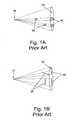
- the scale of image 40 on surface 30 depends on the distance of identical objects 20 from the source 10 ( Fig. 1A ) and/or on the angle of the object with reference to planar surface 30 ( Fig. 1B ).
- the surgeon can not accurately measure distances or the size, shape, and orientation of objects in x-ray images and has to rely on intuition and experience to determine these parameters. The problem is especially serious in the case of surgical procedures that must be carried out using frequent x-ray imagery.
- the invention comprises a grid of radiopaque wires placed between the object being x-rayed (inside a human body) and the planar surface on which the images are recorded and an "angle plate" which is applied to the body to insure parallelism of the x-rays.
- the object of the invention being to provide "an improved radiographic apparatus whereby the exact location of an invisible object, not permeable or difficultly permeable by the so-called "Roentgen” or "X" rays, may be accurately ascertained and measurements made by which operations necessary for the removal of such objects are controlled and guided".
- the invention is a system for measuring the true dimensions and orientation of objects in a two dimensional image.
- the system is comprised of a ruler comprising at least one set of features each comprised of two or more markers that are identifiable in the image and having known spatial relationship between them and a software package comprising programs that allow extension of the ruler and other objects in the two dimensional image beyond their physical dimensions or shape.
- the markers in each set are arranged in one or more rows having known spatial relationship between them. If there is more than one of the sets, at least some of the sets are aligned in a direction non-parallel to the measurement direction or to each other.
- Embodiments of the system are adapted to measuring x-ray images. Embodiments of the system are adapted to enable it to be used for measuring the true dimensions and orientation of objects and for aiding in the identification and location of a surgery tool vs. anatomy in a radiographic image.
- the invention is an apparatus adapted to enable it to take x-ray images and to measure the true dimensions and orientation of objects and to aid in the identification and location of a surgery tool vs. anatomy in those x-ray images.
- the apparatus comprises:
- the software package comprises a program that allows the zero scale on the virtual extension of the ruler to be dragged and moved around at will.
- the software package comprises a program that allows the processing means to measure the angle between two lines projected on the measuring plane.
- the software package comprises a program that allows the processing and display means to provide real time visualization by using either a one or a three dimensional ruler in order to draw how at least a part of the result of the operation will look given the positioning of the ruler or some other surgical tool visible in the image.
- the software package comprises a program that allows the processing and display means to find markers in the image and place templates of implants or other objects on the image.
- the software package comprises a program that allows the processing means to automatically determine the location of a surgical tool in the image and to apply an image enhancement algorithm that automatically concentrates on the specific area of interest to the surgeon.
- the software package comprises a program that allows the processing and display means to synchronize AP and axial images.
- the invention is a ruler for use in the system of the first and second aspects.
- the ruler has at least one set of features each comprised of two or more markers that are identifiable in the image having known spatial relationship between them.
- the markers in each set are arranged in one or more rows having known spatial relationship between them and, if there is more than one of the sets, at least some of the sets are aligned in a direction non-parallel to the measurement direction or to each other.
- the ruler can be a hand-held ruler used to "point and "measure”.
- the ruler may comprise means for slideably attaching it to a tool.
- the ruler may be an integral part of a tool, made by making at least part of the tool from a translucent material and embedding opaque markers into it.
- the ruler may be comprised of small radiopaque markers, with a known spatial relationship between them, embedded in a radiolucent envelope.
- the invention is a method of drawing and displaying on a two dimensional x-ray image measurements of objects visible in said image, graphical information, or templates of surgical devices.
- the method comprises the steps of:
- the method is characterized in that the measurements, graphical information, or templates are not a part of the known object.
- the known object can be a ruler according to the third aspect of the invention, a surgical tool, or an anatomical feature.
- the invention is a system that can be used for measuring the true dimensions in a specific orientation of objects in two and three dimensional images.
- the images considered herein are radiographic images, in particular x-ray images, wherein by x-ray images are meant radiographic images, fluoroscopic images, digital fluoroscopy images, or images taken using any other type that uses x-rays to obtain them.
- x-ray images are meant radiographic images, fluoroscopic images, digital fluoroscopy images, or images taken using any other type that uses x-rays to obtain them.
- the device and methods of the invention can be used in any imaging situation.
- the device and system of the invention are used to measure the true dimensions and orientation of objects that appear in the image and to aid the surgeon in the identification and location of surgery tools vs. anatomy in the radiographic image.
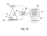
- Fig. 16 symbolically shows how the system of the invention is integrated with an imaging system to improve the users understanding of the images produced with the imaging system.
- the essential components of imaging system 200 are the source of radiation 202 and the detector 204.
- the imaging system 200 is connected to a computer 206.
- object 210 blocks some of the radiation causing a shadow to appear on the detector.
- the output signals from detector 204 are sent to computer 206 where they are processed to produce images that can be stored in the memory of computer 206 and/or displayed on display device 208.
- the system of the invention comprises two components: a calibration device 70, which is called a "ruler” herein and a computer software package 216.
- Radiolucent ruler 70 comprises radiopaque markers 76. It is placed in the space between source 202 and detector 204 such that at least some of the markers 76 will be visible in the images gathered by imaging system 200.
- Computer software package 216 is loaded into computer 206 in order to provide the computer with advanced capabilities for processing and displaying the images as a graphical overlay, displayed over the x-ray image on the display 206, thereby providing the user with information not previously available. Illustrative embodiments of the ruler and of the software as well as descriptions of the new types of visual information that can be provided to the user will be described herein below.
- markers is used to mean features that are visible in the image, by virtue of their color, luminance or intensity. In the case of x-ray images, markers have a different radio-opacity than their immediate surrounding, or comprise different radio-opacity levels. Markers are regarded as a singular point in space, e.g. the center of a ball or a corner of a cubical shape, which is well defined and can be noticed in the image.
- markers and “feature” are used interchangeably.
- the ruler comprises two or more features having a known spatial relationship between them that are visible and recognizable in a radiographic image.
- the two or more features are aligned parallel to the measurement direction.
- the associated software allows, amongst many other modes of operation to be described herein, the automatic recognition of features of the ruler in the radiographic image and the use of these features to create a virtual extension of the ruler, i.e. to extend the ruler beyond its physical dimensions, and drawing the virtual extension on the image as an overlay.
- the invention enables the surgeon who is pointing the ruler and looking at the image to accurately measure dimensions of objects that appear in the radiographic image.
- the invention is especially useful and convenient for use with x-ray imaging in which frequently it is desired to measure the internal organs, bones, etc. of a body.
- the invention can be used with any technique of producing two dimensional images, e.g. regular photography.
- the invention in its various embodiments, can be used to assist the operator in any procedure in which it is desirable or necessary to measure distances or dimensions of objects in radiographic images.
- Such procedures range from common chest x-rays, that are analyzed “off-line”, to orthopedic and other surgical procedures that can only be carried out "on-line", i.e. with the aid of inter-surgery radiographic imagery using, for example, a mobile C-arm x-ray unit.
- Typical non-limitative examples of on-line procedures that can be performed with the aid of the invention are:
- DHS dynamic hip screw
- a specific protocol for carrying out the surgical procedure can be downloaded from the web site of Smith & Nephew at [http://www.smithnephew.com/Downloads/71180375.pdf].
- Fig. 2 shows a compression hip plate assembly 50 manufactured by Smith & Nephew.
- the assembly comprises a plate 54 that fits against the outer surface of the femur with an attached barrel 52 that fits into a hole bored into the femur. After reduction and fixation of the fracture a hole is bored into the bone through the neck and into the head of the femur in order to attach lag screw 56. After lag screw 56 has been screwed into the head of the femur, the barrel is inserted into the hole, the plate is positioned on the side of the femur, and compression screw 60 is screwed in to attach the plate 54 to the lag screw and tightened to bring the broken pieces of bone together.
- Self tapping bone screws 58 are used to attach the plate firmly to the shaft of the femur and if necessary, depending on the type of break, cannulated or cancellous screw 62 can be inserted into the bone to capture medial fragments.
- hip plate kits available to the surgeon having many variations of the basic design. The variations include, for example, the length of lag screw 56, the angle between screw 56 and plate 54, and the number of cortical screws 58.
- the most demanding part of the procedure is creating the hole into which the lag screw is inserted.
- the hole must pass through the bone in a path following the central axis of the neck of the femur towards the apex of the femoral head.
- the surgeon assisted by a series of x-ray images taken during the course of the proceeding, uses a small diameter guide drill to make an initial guide hole.
- the first problem is to determine the neck angle to select an appropriate angle plate, which is used to help determine the proper entry point and to aim the guide drill.
- the surgeon referring to the x-ray images, estimates the correct angle and entry point and begins to drill with the guide drill.
- lag screw it is essential that the lag screw be attached to as much of the bone as possible; however sufficient bone must remain at the apex of the head to prevent the lag screw from breaking through into the hip joint when the screw is inserted in the hole. This issue involves not only measurement of drilling orientation but also of drilling depth.
- TAD tip-apex distance
- X ap and D ap mark the distances from the tip of the lag screw to the apex of the femoral head and the measured diameter of the lag screw measured on an anteroposterior (AP) radiograph, respectively.
- X lat and D lat mark the same parameters measured on a lateral radiograph, and D true is the actual diameter of the lag screw.
- Figs. 4 , 5A, and 5B illustrate two embodiments of a one-dimensional ruler of the invention.
- ruler 70 is comprised of a cylinder 72 of radiolucent material.
- a slot 74 is created lengthwise in cylinder 72 so that the ruler can be slipped over the surgical tool, e.g. a guide, i.e. a thin bone drill sometimes known as a guide wire, without the necessity of releasing the guide from the power drill.
- the dimensions of the slot are such that the longitudinal axis of the guide and cylinder 72 coincide when ruler 70 is attached to the guide.
- the guide fits tightly in the slot so that the ruler will not slide freely but can be shifted easily by the surgeon to a new position when desired.
- Some embodiments of the ruler will rotate with the guide and other embodiments of the ruler can be attached so that the guide may rotate without rotating the attached ruler.
- Metal balls 76 are embedded into cylinder 72 in rows that are parallel to the direction of slot 74. Metal balls "floating" in a plastic cylinder are preferably used so that the x-ray signature of the ruler will be dark circles that are easily detectable in the image.
- One row of balls 76 is theoretically sufficient; however it is preferred that at least three rows of balls 76, equally radially spaced around the circumference of the base of cylinder 72, be used to insure that at any position of the ruler on the guide at least one row of balls will not be overlaid by the radiopaque guide or another row of balls, and will be visible on the x-ray image.
- the exact distance between balls 76 is known so that when their shadows are detected on the x-ray image the dedicated software of the invention can identify them and measure the apparent distance between them directly from the image and use this measurement together with the known actual distance to calculate the scale that is used to create the overlays that allow the surgeon to determine the exact position of the guide relative to the anatomical structure, dimensions, and other related information displayed on a screen in "real time".
- the dedicated software of the invention can identify them and measure the apparent distance between them directly from the image and use this measurement together with the known actual distance to calculate the scale that is used to create the overlays that allow the surgeon to determine the exact position of the guide relative to the anatomical structure, dimensions, and other related information displayed on a screen in "real time".
- only two balls 76 in one row are needed to be visible in the image in order to create an acceptable approximation of the C-arm magnification factor and the sizes of organs and tools for most common cases.
- the distance between markers i.e. the scale
- the distance between markers will grow smaller to one direction and larger in the other direction, changing with the distance from the x-ray source.
- the rate of change of the distance can be measured and therefore an accurate scale in both directions can be calculated.
- Fig. 5A shows another embodiment of a ruler 70' of the invention.
- the radiolucent body 80 of the ruler is roughly a prism having an isosceles triangle as its base. The sides of the prism are cut away to leave a Y-shaped cross section.
- a row of metal balls 76 (seen in Fig. 5B , which is a cross-sectional view of ruler 70') is embedded at the apex of each of the arms of the "Y".
- a slot 74 is created along the longitudinal symmetry axis of body 80 of ruler 70'.
- Body 80 is slipped over guide 78 and then a clip 82 is attached to body 80 to hold guide 78 in slot 74. This can be done with the guide attached to the drill.
- the width of slot 74 need not necessarily be essentially equal to the diameter of the guide but it can be wide enough to allow the ruler to be attached to guides having a wide range of diameters.
- Clip 82 comprises a spring loaded brake (not shown) that locks ruler 70' in place, preventing it from sliding along guide 78. Pressing downward on clip 82 in the direction of arrow 84 releases the brake allowing ruler 70' to be moved and repositioned along the guide. Repositioning can be easily accomplished by the surgeon using one hand at any time during the procedure.
- Fig. 6 illustrates an embodiment of a three dimensional ruler 70" of the invention.
- the radiolucent body 86 of the ruler has an "L" shaped cross section. Rows of radiopaque balls 76 are embedded in the walls of body 86.
- a suitable arrangement e.g. a slit and/or a clip such as described above, are provided to slidingly hold ruler 70" in place on guide 78.
- markers are described herein with regard to specific illustrative examples of the ruler.
- the minimal requirement of the invention for the number and arrangement of markers is one of the following:
- the triangular sleeve with handle that is used by orthopedic surgeons to aid them in maintaining the alignment of the drill in a DHS placement procedure, as known to persons skilled in the art, can be modified by embedding a three dimensional ruler of the invention inside it, in which case, the modified sleeve itself can be used to fulfill the functions of the ruler of the invention that are described herein.
- the sleeve is made of radiolucent material and comprises a set of metal balls, arranged in a known spatial arrangement, such that the 3D orientation of the ruler may be calculated using the balls that appear in the image.
- Figs. 9A to Fig. 9C respectively show front and back perspective views and a cross-sectional view of a handle 90 comprising a ruler of the invention that can replace the traditional triangular sleeve used by surgeons to aid in aligning a guide drill.
- handle 90 has a "T" shape with a crosspiece 92 at the top of shaft 93 that allows the user to easily and firmly grip handle 90 with one hand.
- a foot 94 At the bottom of shaft 93 is a foot 94.
- the bottom surface of foot 94 comprises means, e.g. cleats 96, to prevent the device from sliding on the surface of the skin.
- the exit hole 98 of slot 74 Fig.
- FIG. 9C through which the guide drill passes can be seen on the bottom of foot 94.
- At least the foot 94 and the lower portion of shaft 93 (through which slot 74 passes) of handle 90 are made of a radiolucent material.
- embedded in this material are two rows comprised of five radiopaque markers 76 each, a horizontal row embedded in the foot 94 and a vertical row embedded in the lower part of shaft 93. Notice that the markers in each row are not equally spaced and that neither of the rows of markers is aligned in parallel to the direction of the drilling.
- the software of the system can identify the markers 76 and from them determine the location and orientation of the handle 90, from this the exact orientation of slot 74, and can create a virtual extension of the guide that is inserted into slot 74, in the direction of drilling, beyond its physical dimension.
- a ruler need not be attached to the drill and the system of the invention will recognize the handle and can extrapolate it in both directions and can also display the implant template, i.e., a graphic overlay of where the implant would be, including all its parts, at the current position of the triangle (see, for example, Fig, 14 and Fig. 15 ).
- This approach allows an "intra-operative real time" visualization and measurement ability using the tools that are familiar to the surgeon.
- preferred embodiments of three dimensional rulers can be constructed comprising two sets of non-parallel rows of markers in order to provide a device for which the markers will be identified even when the ruler is partially occluded by other objects, e.g. bones or tools in the image.
- a three dimensional grid can be projected onto the image.
- embodiments of the ruler of the invention comprise an elongated radiolucent body in which rows of radiopaque markers of known size and distance apart are symmetrically embedded.
- the ruler of the invention can be: a hand-held ruler used to "point: and “measure”; the ruler can comprise means for slideably attaching it to a surgical tool, e.g. handle 90 shown in Figs. 9A to 9C ; or the ruler can be an integral part of a surgical tool, possibly made by making at least part of the tool from a translucent material and embedding radiopaque markers into it.
- the ruler can be a one dimensional ruler in which the rows of radiopaque markers are parallel to the measuring direction or a three dimensional ruler in which a non parallel rows of markers are embedded.
- the ruler could comprise a metal comb or a metal jig, with no translucent material.
- the radiopaque markers would then be either characteristic features of the ruler, e.g. the teeth of the comb, or could be, e.g. metal balls attached to the body of the ruler.
- the ruler when the ruler is attached to a surgical tool as will be demonstrated by example hereinbelow, during a medical procedure the ruler stays in a fixed position, e.g. at a location on the surface of the body or an organ within the body of a patient, while the tool is advanced into or withdrawn from the body or organ during the course of a diagnostic or surgical procedure.
- the ruler is made of bio-compatible USP class 6 materials and is reusable after sterilization using, for example, ETO.
- the entire ruler, except for the metal balls, is made of plastic. Under x-ray the ruler is seen as semi transparent and the metal balls are seen "floating" around the guide/drill. Based on these fundamentals and the examples of the embodiments described herein, skilled persons should have no trouble designing a ruler suitable for use with any diagnostic or surgical tool.
- Fig. 7 and Fig. 8 schematically show respectively how one and two dimensional virtual extensions of the ruler of the invention are created overlaying the x-ray image of the object of interest.
- object 20 and radiopaque balls 76 embedded in a ruler of the invention that is attached to guide drill 78 are shown positioned in the path of a beam of x-rays emitted by source 10.
- the dashed lines represent the shadows of the radiopaque objects that form images 40 on the electronic camera.
- the digital signals from the camera are processed using the software package of the invention to determine the distance between the images of the balls of the ruler. From the measured and known distances a scale factor is determined and a virtual extension 88 of the ruler is constructed.
- the virtual extension can be added as an overlay on the displayed x-ray image in a number of ways that can be selected by the operator.
- the suggested display mode is to place the graphic presentation of the virtual extension exactly on top of the longitudinal axis of the guide drill with the origin at the distal tip of the drill, as seen in the x ray image. This is shown in Fig. 7 on the image plane representing the displayed image in the actual system. In this way, the surgeon can, using both forward distance scales and rearward distance scales, determine respectively how much farther the drill must be advanced and how far into the object the drill has penetrated.
- display features are possible, e.g. color coding to easily distinguish between forward and rearward distances, the addition of transverse scales at locations selected by the operator to enable measurement of the distance from the center of the drill to the sides of the object for example to confirm that the hole is being drilled exactly through the center of the object, and the addition of color coded markings to indicate when the drill is approaching and/or has arrived at the location that drilling should cease.
- color coding to easily distinguish between forward and rearward distances
- transverse scales at locations selected by the operator to enable measurement of the distance from the center of the drill to the sides of the object for example to confirm that the hole is being drilled exactly through the center of the object
- color coded markings to indicate when the drill is approaching and/or has arrived at the location that drilling should cease.
- Fig. 8 is similar to Fig. 7 with the exception that use of the three dimensional ruler provides sufficient information for the software to construct a two dimensional grid that can be displayed on the screen as an overlay on top of the x-ray image.
- the three dimensional ruler can provide a complete three dimensional orientation, the grid could be drawn in any orientation, and not just the original orientation of the ruler (as shown in the figure).
- the system of the invention is used with a C-arm X-ray unit or some other imaging system. It comprises a ruler, and software that enables display of the virtual extension and allows display of the overlays and other features described herein, e.g. the software may include computer vision and recognition algorithms that are used to identify implants, surgical tools and anatomical features and to draw their counterparts or extensions during the operation as an overlay on the x-ray image (see Fig. 11 ).
- the software works in semi-automatic mode wherein it allows the user to mark on the balls on the computer screen, e.g. by pointing to and clicking on them using a computer mouse, and then calculates the scale and draws the virtual extension.
- the process may be started with a user click and then the software automatically searches for the markers and for the guide in the next image.
- Skilled persons will recognize that the system can be given the ability to display the images in many different formats to assist the surgeon, e.g. different colors can be used to differentiate how far the drill has penetrated into the bone from the remaining distance.
- audible signals signifying, e.g. the remaining distance or when to stop drilling can be provided.
- an anti-distortion system for extra accuracy.
- the anti-distortion system is a conventional one, as known to persons skilled in the art, comprises a grid placed on the image intensifier (the receiving end of the C-arm) and software that uses the image of the grid to correct the image obtained from the C-arm.
- Anti-distortion systems suitable for use with the present invention are described in: [ Gronenschild E., "Correction for geometric image distortion in the x-ray imaging chain: local technique versus global technique" Med Phys. 1999, Dec; 26(12):2602-16 ]. In cases in which an anti-distortion system is used, the detection of the ruler markers using the software of the present invention has to be done on the image after the anti-distortion process.
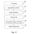
- Fig. 17 is a flow chart outlining the main stages in processing and displaying the images using the system of the invention.
- the x-ray image obtained using the imaging system 200 undergoes an image distortion process.
- This phase is not mandatory, and depends on the imaging system. Some imaging systems do not create significant distortions and for these systems this phase can be skipped. Image distortion correction is done in any one of the standard ways, known in the art.
- the next stage 502 is marker identification in the image.
- the marker identification can be done either manually, where the user points at the location of the markers using a pointing device, such as a computer mouse; can be done in a semi-automatic manner, where some user input is required and some of the marker identification is done automatically; or can be done in a fully automatic manner, where an image processing algorithm provided in the software of the system is used to detect the markers in the image.
- the software of the system calculates the scale, using the markers in the image identified in stage 502. If a one dimensional ruler has been used, then the markers are co-linear and the only scale that can be deduced is in the direction of the markers. Since the magnification of an object depends on its distance from the x-ray source, if only two markers are used, the exact position and orientation of the ruler can not be determined, since a rotation of the ruler may have the same affect as a change of distance from the x-ray source, on the distance between the markers on the image (see Figs. 1A and 1B ).
- ruler extrapolation can not be achieved with high accuracy because, if the measurement direction is at an acute angle to the x-rays, scaling changes rapidly along the direction of measurement.
- the system draws an overlay over the x-ray image.
- the overlay may include any type of graphical or other information, drawn or printed over the image. Amongst other things, it may include a virtual extension of a drill, an implant image, taken from a pre-stored library of implants, or a virtual drawing of a measurement ruler, aligned with the device.
- the overlay can make use of the location and orientation of the device in the image.
- Preferred embodiments may include a GUI that enables the user to easily select and customize the overlay shown over the images.
- DHS dynamic hip screw
- the software package of the invention enables the surgeon to apply templates of the tools and lag screws of different dimensions and to determine accurate measurements of the anatomical features to plan exactly the operation including screw selection and to visualize the end result.
- Fig. 15 shows this feature of the operation planning stage.
- Fig. 12 shows the display during operation after the skin was already cut and some of the surgical tools were inserted to the body.
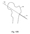
- the drill 78 is about to enter the femur and the surgeon uses a triangular sleeve to enter at the correct angle (135 degrees).
- a two dimensional grid has been drawn to illustrate how the ruler of the invention and its virtual extension 104 would appear.
- Fig. 13 shows the situation after drilling with the guide drill 78.
- the virtual ruler 104 displayed on the screen overlaying the guide and the bone allows the surgeon to see exactly how far the drill has penetrated the bone and to confirm that the path is correct.
- a three dimensional ruler is used to determine the plane on which to draw the line perpendicular to the drilling direction, i.e. to correct for the change of scale of the ruler on the drill caused by the fact that the drill is tilted at an angle relative to the plane of the image.
- a one dimensional ruler could be just as useful; but in either case, the surgeon can see how far the guide tip is from the hip joint. This is useful for determining the expected distance from the joint. Note that this is not exactly the tip apex distance, but rather a more accurate 3D measurement, that is similar in concept to the TAD.
- the virtual ruler allows the surgeon to accurately measure the tip-apex distance and verify that the surgery has been performed properly.
- embodiments of the invention are very versatile when applied to orthopedic surgery and the software package may have the capability of allowing the operator to choose from many different operating modes, depending on the requirements or stage of the procedure.
Landscapes
- Engineering & Computer Science (AREA)
- Health & Medical Sciences (AREA)
- Life Sciences & Earth Sciences (AREA)
- Physics & Mathematics (AREA)
- Medical Informatics (AREA)
- Surgery (AREA)
- Theoretical Computer Science (AREA)
- General Physics & Mathematics (AREA)
- General Health & Medical Sciences (AREA)
- Nuclear Medicine, Radiotherapy & Molecular Imaging (AREA)
- Pathology (AREA)
- Veterinary Medicine (AREA)
- Biomedical Technology (AREA)
- Heart & Thoracic Surgery (AREA)
- Molecular Biology (AREA)
- Public Health (AREA)
- Animal Behavior & Ethology (AREA)
- Radiology & Medical Imaging (AREA)
- Computer Vision & Pattern Recognition (AREA)
- High Energy & Nuclear Physics (AREA)
- Optics & Photonics (AREA)
- Biophysics (AREA)
- Computer Graphics (AREA)
- Computer Hardware Design (AREA)
- General Engineering & Computer Science (AREA)
- Software Systems (AREA)
- Oral & Maxillofacial Surgery (AREA)
- Human Computer Interaction (AREA)
- Quality & Reliability (AREA)
- Apparatus For Radiation Diagnosis (AREA)
Claims (4)
- Système pour évaluer les dimensions et/ou l'orientation d'objets dans une image bidimensionnelle, comprenant :un moyen d'imagerie (200, 202, 204) pour imager un os et des objets à proximité de l'os pour produire une image bidimensionnelle ;un outil (70) avec au moins un jeu de marqueurs (76), ledit au moins un jeu comprenant deux ou plusieurs marqueurs qui sont identifiables dans ladite image, et lesdits marqueurs ayant des relations spatiales connues entre eux,caractérisé parune logique de traitement d'image (216) conçue pour fournir une extension virtuelle (104) dudit outil basée sur une identification de ses marqueurs associés dans une image bidimensionnelle comprenant ledit outil.
- Système selon la revendication 1, dans lequel les marqueurs de chaque jeu sont disposés en une ou plusieurs rangées ayant des relations spatiales connues entre elles, et, s'il y a plus d'un desdits jeux, au moins certains desdits jeux sont alignés dans une direction non parallèle à la direction de mesure ou les uns aux autres.
- Système selon la revendication 1, ledit système étant conçu pour mesurer des objets dans des images aux rayons X.
- Système selon la revendication 1, ledit système étant conçu pour mesurer les dimensions et l'orientation d'objets.
Priority Applications (1)
| Application Number | Priority Date | Filing Date | Title |
|---|---|---|---|
| EP14166253.6A EP2779096A1 (fr) | 2007-06-21 | 2008-06-19 | Système pour mesurer les dimensions réelles et l'orientation d'objets dans une image bidimensionnelle |
Applications Claiming Priority (2)
| Application Number | Priority Date | Filing Date | Title |
|---|---|---|---|
| IL184151A IL184151A0 (en) | 2007-06-21 | 2007-06-21 | X-ray measurement method |
| PCT/IL2008/000841 WO2008155772A1 (fr) | 2007-06-21 | 2008-06-19 | Système pour mesurer les vraies dimensions et l'orientation d'objets dans une image bidimensionnelle |
Related Child Applications (2)
| Application Number | Title | Priority Date | Filing Date |
|---|---|---|---|
| EP14166253.6A Division EP2779096A1 (fr) | 2007-06-21 | 2008-06-19 | Système pour mesurer les dimensions réelles et l'orientation d'objets dans une image bidimensionnelle |
| EP14166253.6A Division-Into EP2779096A1 (fr) | 2007-06-21 | 2008-06-19 | Système pour mesurer les dimensions réelles et l'orientation d'objets dans une image bidimensionnelle |
Publications (2)
| Publication Number | Publication Date |
|---|---|
| EP2179397A1 EP2179397A1 (fr) | 2010-04-28 |
| EP2179397B1 true EP2179397B1 (fr) | 2014-08-20 |
Family
ID=39846950
Family Applications (2)
| Application Number | Title | Priority Date | Filing Date |
|---|---|---|---|
| EP14166253.6A Withdrawn EP2779096A1 (fr) | 2007-06-21 | 2008-06-19 | Système pour mesurer les dimensions réelles et l'orientation d'objets dans une image bidimensionnelle |
| EP08763599.1A Not-in-force EP2179397B1 (fr) | 2007-06-21 | 2008-06-19 | Système pour mesurer les vraies dimensions et l'orientation d'objets dans une image bidimensionnelle |
Family Applications Before (1)
| Application Number | Title | Priority Date | Filing Date |
|---|---|---|---|
| EP14166253.6A Withdrawn EP2779096A1 (fr) | 2007-06-21 | 2008-06-19 | Système pour mesurer les dimensions réelles et l'orientation d'objets dans une image bidimensionnelle |
Country Status (5)
| Country | Link |
|---|---|
| US (4) | US8611697B2 (fr) |
| EP (2) | EP2779096A1 (fr) |
| CN (1) | CN101779223B (fr) |
| IL (1) | IL184151A0 (fr) |
| WO (1) | WO2008155772A1 (fr) |
Cited By (1)
| Publication number | Priority date | Publication date | Assignee | Title |
|---|---|---|---|---|
| US9433390B2 (en) | 2007-06-21 | 2016-09-06 | Surgix Ltd. | System for measuring the true dimensions and orientation of objects in a two dimensional image |
Families Citing this family (105)
| Publication number | Priority date | Publication date | Assignee | Title |
|---|---|---|---|---|
| US8090166B2 (en) | 2006-09-21 | 2012-01-03 | Surgix Ltd. | Medical image analysis |
| AU2007350982A1 (en) | 2006-11-10 | 2008-10-23 | Dorian Averbuch | Adaptive navigation technique for navigating a catheter through a body channel or cavity |
| US10105168B2 (en) | 2008-01-09 | 2018-10-23 | Stryker European Holdings I, Llc | Stereotactic computer assisted surgery based on three-dimensional visualization |
| EP2297673B1 (fr) | 2008-06-03 | 2020-04-22 | Covidien LP | Procédé d'alignement basé sur des caractéristiques |
| US8218847B2 (en) | 2008-06-06 | 2012-07-10 | Superdimension, Ltd. | Hybrid registration method |
| EP2310839A4 (fr) * | 2008-06-18 | 2011-08-03 | Surgix Ltd | Procédé et système pour assembler de multiples images en une image panoramique |
| FR2937530B1 (fr) | 2008-10-24 | 2012-02-24 | Biospace Med | Mesure de grandeurs geometriques intrinseques a un systeme anatomique |
| US8908995B2 (en) * | 2009-01-12 | 2014-12-09 | Intermec Ip Corp. | Semi-automatic dimensioning with imager on a portable device |
| EP2501303B1 (fr) | 2009-11-20 | 2020-02-12 | Zimmer Knee Creations, Inc. | Instruments de navigation et de positionnement pour la réparation des articulations |
| AU2010321743A1 (en) | 2009-11-20 | 2012-07-12 | Knee Creations, Llc | Coordinate mapping system for joint treatment |
| US8821504B2 (en) | 2009-11-20 | 2014-09-02 | Zimmer Knee Creations, Inc. | Method for treating joint pain and associated instruments |
| EP2501314B1 (fr) | 2009-11-20 | 2019-04-10 | Zimmer Knee Creations, Inc. | Instruments pour cibler un défaut articulaire |
| US8608802B2 (en) | 2009-11-20 | 2013-12-17 | Zimmer Knee Creations, Inc. | Implantable devices for subchondral treatment of joint pain |
| US8801800B2 (en) | 2009-11-20 | 2014-08-12 | Zimmer Knee Creations, Inc. | Bone-derived implantable devices and tool for subchondral treatment of joint pain |
| CN102740784B (zh) | 2009-11-20 | 2015-09-09 | 膝部创造物有限责任公司 | 用于对关节的可变角度进路的仪器 |
| US8951261B2 (en) | 2009-11-20 | 2015-02-10 | Zimmer Knee Creations, Inc. | Subchondral treatment of joint pain |
| US10588647B2 (en) | 2010-03-01 | 2020-03-17 | Stryker European Holdings I, Llc | Computer assisted surgery system |
| US8702713B2 (en) | 2011-01-26 | 2014-04-22 | Warsaw Orthopedic, Inc. | Instruments and techniques for adjusting relative positioning of bones or bony tissues |
| DE102011075435A1 (de) * | 2011-05-06 | 2012-11-08 | Siemens Aktiengesellschaft | Anzeigeeinheit |
| US8468705B2 (en) | 2011-07-08 | 2013-06-25 | John Schneider | Electronic scaling ruler |
| US8886449B2 (en) | 2012-01-13 | 2014-11-11 | Qualcomm Incorporated | Calibrated hardware sensors for estimating real-world distances |
| US9375167B2 (en) | 2012-03-22 | 2016-06-28 | Sizer Llc | Blood vessel sizing device |
| US11419523B2 (en) | 2012-03-22 | 2022-08-23 | Sizer Llc | Blood vessel sizing device and method for sizing blood vessel |
| US8971995B2 (en) | 2012-03-22 | 2015-03-03 | Sizer Llc | Blood vessel sizing device |
| KR101608869B1 (ko) | 2012-09-07 | 2016-04-04 | 삼성전자주식회사 | 대상체의 분할 영상 또는 의료 영상에 가상 자를 표시하는 방법 및 의료 영상 획득 장치, 및 가상 자가 표시된 분할 영상 또는 의료 영상을 디스플레이하는 방법 및 장치 |
| WO2014048447A1 (fr) | 2012-09-27 | 2014-04-03 | Stryker Trauma Gmbh | Détermination d'une position rotationnelle |
| US10743945B2 (en) | 2012-10-02 | 2020-08-18 | Radlink, Inc. | Surgical method and workflow |
| EP2928404A1 (fr) * | 2012-12-10 | 2015-10-14 | Koninklijke Philips N.V. | Règle numérique et réticule pour dénervation rénale |
| US10105151B2 (en) * | 2012-12-12 | 2018-10-23 | Wright Medical Technology, Inc. | Instrument for intra-operative implant templating using fluoroscopy |
| AU2014217929B2 (en) | 2013-02-18 | 2018-04-19 | Orthogrid Systems, Inc. | Alignment plate apparatus and system and method of use |
| US10526232B2 (en) * | 2013-05-30 | 2020-01-07 | Ppg Industries Ohio, Inc. | Microwave heating glass bending process |
| JP6511050B2 (ja) * | 2013-07-23 | 2019-05-08 | コーニンクレッカ フィリップス エヌ ヴェKoninklijke Philips N.V. | イメージング装置を追跡装置と位置合わせする位置合わせシステム、イメージングシステム、介入システム、位置合わせ方法、イメージングシステムの作動方法、位置合わせコンピュータプログラム、及びイメージングコンピュータプログラム |
| US9402660B2 (en) | 2013-09-05 | 2016-08-02 | Warsaw Orthopedic, Inc. | Surgical instrument and method |
| CN110136191B (zh) * | 2013-10-02 | 2023-05-09 | 基文影像公司 | 用于体内对象的大小估计的系统和方法 |
| US20150157197A1 (en) * | 2013-12-09 | 2015-06-11 | Omer Aslam Ilahi | Endoscopic image overlay |
| CA2953694A1 (fr) | 2014-07-02 | 2016-01-07 | Covidien Lp | Alignement tdm |
| US9633431B2 (en) | 2014-07-02 | 2017-04-25 | Covidien Lp | Fluoroscopic pose estimation |
| US9974525B2 (en) | 2014-10-31 | 2018-05-22 | Covidien Lp | Computed tomography enhanced fluoroscopic system, device, and method of utilizing the same |
| US11382816B2 (en) | 2015-06-05 | 2022-07-12 | Stryker Corporation | Surgical table and accessories to facilitate hip arthroscopy |
| US10702226B2 (en) | 2015-08-06 | 2020-07-07 | Covidien Lp | System and method for local three dimensional volume reconstruction using a standard fluoroscope |
| US10716525B2 (en) | 2015-08-06 | 2020-07-21 | Covidien Lp | System and method for navigating to target and performing procedure on target utilizing fluoroscopic-based local three dimensional volume reconstruction |
| US10674982B2 (en) | 2015-08-06 | 2020-06-09 | Covidien Lp | System and method for local three dimensional volume reconstruction using a standard fluoroscope |
| US10098707B2 (en) | 2015-08-17 | 2018-10-16 | Orthogrid Systems Inc. | Surgical positioning system, apparatus and method of use |
| US11234768B1 (en) | 2015-10-15 | 2022-02-01 | Dartmouth-Hitchcock Clinic | Screen-mounted trajectory and aiming guide for use with fluoroscopy |
| US10052170B2 (en) | 2015-12-18 | 2018-08-21 | MediLux Capitol Holdings, S.A.R.L. | Mixed reality imaging system, apparatus and surgical suite |
| US11386556B2 (en) | 2015-12-18 | 2022-07-12 | Orthogrid Systems Holdings, Llc | Deformed grid based intra-operative system and method of use |
| US10201320B2 (en) | 2015-12-18 | 2019-02-12 | OrthoGrid Systems, Inc | Deformed grid based intra-operative system and method of use |
| US10010372B1 (en) | 2016-01-06 | 2018-07-03 | Paul Beck | Marker Positioning Apparatus |
| JP6698392B2 (ja) * | 2016-03-22 | 2020-05-27 | 富士フイルム株式会社 | 画像処理装置、放射線画像撮影システム、画像処理方法、及び画像処理プログラム |
| US11051859B2 (en) | 2016-04-27 | 2021-07-06 | Warsaw Orthopedic, Inc. | Spinal correction system and method |
| USD842479S1 (en) | 2016-04-27 | 2019-03-05 | Warsaw Orthopedic, Inc. | Spinal implant |
| US10390862B2 (en) | 2016-04-27 | 2019-08-27 | Warsaw Orthopedic, Inc. | Spinal correction system and method |
| US10194958B2 (en) | 2016-04-27 | 2019-02-05 | Warsaw Othopedic, Inc. | Spinal correction system and method |
| US10748319B1 (en) | 2016-09-19 | 2020-08-18 | Radlink, Inc. | Composite radiographic image that corrects effects of parallax distortion |
| WO2018053486A1 (fr) | 2016-09-19 | 2018-03-22 | Radlink, Inc. | Image radiographique composite corrigeant les effets d'une distorsion de parallaxe |
| US10143533B2 (en) | 2016-10-06 | 2018-12-04 | Sizer Llc | Blood vessel sizing device |
| US10543022B2 (en) | 2016-10-11 | 2020-01-28 | Warsaw Orthopedic, Inc. | Spinal implant system and method |
| CN110177492A (zh) | 2016-11-18 | 2019-08-27 | 斯特赖克公司 | 用于治疗关节的方法和设备,包括髋关节中的凸轮型股骨髋臼撞击症和髋关节中的钳夹型股骨髋臼撞击症的治疗 |
| US11559455B2 (en) | 2017-02-06 | 2023-01-24 | Stryker Corp. | Distraction frame for effecting hip distraction |
| US11510805B2 (en) | 2017-02-06 | 2022-11-29 | Stryker Corp. | Anatomical gripping system for gripping the leg and foot of a patient when effecting hip distraction and/or when effecting leg positioning |
| AU2018214679A1 (en) | 2017-02-06 | 2019-08-29 | Stryker Corp. | Method and apparatus for supporting and stabilizing a patient during hip distraction |
| US10610325B2 (en) | 2017-02-16 | 2020-04-07 | Canon U.S.A., Inc. | Medical guidance apparatus |
| US11793579B2 (en) | 2017-02-22 | 2023-10-24 | Covidien Lp | Integration of multiple data sources for localization and navigation |
| AU2018232490B2 (en) * | 2017-03-09 | 2019-07-25 | Smith & Nephew Asia Pacific Pte. Limited | Sagittal rotation determination |
| US20180314797A1 (en) * | 2017-05-01 | 2018-11-01 | Rohit Madan | Cephalometric analysis and patient management software application for mobile devices |
| USD878836S1 (en) | 2017-08-17 | 2020-03-24 | Stryker Corp. | Table extender |
| US10675099B2 (en) | 2017-09-22 | 2020-06-09 | Canon U.S.A., Inc. | Needle insertion guide device and system, and method of providing control guidance for needle insertion guide device |
| US11197723B2 (en) | 2017-10-09 | 2021-12-14 | Canon U.S.A., Inc. | Medical guidance system and method using localized insertion plane |
| US10893843B2 (en) | 2017-10-10 | 2021-01-19 | Covidien Lp | System and method for identifying and marking a target in a fluoroscopic three-dimensional reconstruction |
| US12004849B2 (en) | 2017-12-11 | 2024-06-11 | Covidien Lp | Systems, methods, and computer-readable media for non-rigid registration of electromagnetic navigation space to CT volume |
| WO2019118501A2 (fr) | 2017-12-11 | 2019-06-20 | Hologic, Inc. | Système de localisation par ultrasons avec marqueurs de site de biopsie perfectionnés |
| US11464569B2 (en) | 2018-01-29 | 2022-10-11 | Stryker Corporation | Systems and methods for pre-operative visualization of a joint |
| US11364004B2 (en) | 2018-02-08 | 2022-06-21 | Covidien Lp | System and method for pose estimation of an imaging device and for determining the location of a medical device with respect to a target |
| US10930064B2 (en) | 2018-02-08 | 2021-02-23 | Covidien Lp | Imaging reconstruction system and method |
| US11464576B2 (en) | 2018-02-09 | 2022-10-11 | Covidien Lp | System and method for displaying an alignment CT |
| JP7237099B2 (ja) | 2018-06-22 | 2023-03-10 | ホロジック, インコーポレイテッド | 多位置超音波システム |
| US10646261B2 (en) | 2018-07-24 | 2020-05-12 | Warsaw Orthopedic, Inc. | Multi-purpose screwdriver and method of use |
| US11617621B2 (en) | 2018-08-03 | 2023-04-04 | Canon U.S.A., Inc. | System and method for multi-probe guidance |
| JP6962976B2 (ja) | 2018-08-15 | 2021-11-05 | キヤノン ユーエスエイ, インコーポレイテッドCanon U.S.A., Inc | 医療用ツールガイダンス装置 |
| US11540794B2 (en) | 2018-09-12 | 2023-01-03 | Orthogrid Systesm Holdings, LLC | Artificial intelligence intra-operative surgical guidance system and method of use |
| EP3852645A4 (fr) | 2018-09-12 | 2022-08-24 | Orthogrid Systems, SAS | Système de guidage chirurgical intra-opératoire à intelligence artificielle et procédé d'utilisation |
| LU101007B1 (en) | 2018-11-26 | 2020-05-26 | Metamorphosis Gmbh | Artificial-intelligence based reduction support |
| LU101009B1 (en) | 2018-11-26 | 2020-05-26 | Metamorphosis Gmbh | Artificial-intelligence-based determination of relative positions of objects in medical images |
| US11925333B2 (en) | 2019-02-01 | 2024-03-12 | Covidien Lp | System for fluoroscopic tracking of a catheter to update the relative position of a target and the catheter in a 3D model of a luminal network |
| US12502218B2 (en) | 2019-02-08 | 2025-12-23 | Stryker Corporation | Systems and methods for treating a joint |
| US12089902B2 (en) | 2019-07-30 | 2024-09-17 | Coviden Lp | Cone beam and 3D fluoroscope lung navigation |
| US12059281B2 (en) | 2019-08-19 | 2024-08-13 | Covidien Lp | Systems and methods of fluoro-CT imaging for initial registration |
| US11864935B2 (en) | 2019-09-09 | 2024-01-09 | Covidien Lp | Systems and methods for pose estimation of a fluoroscopic imaging device and for three-dimensional imaging of body structures |
| US11931111B2 (en) | 2019-09-09 | 2024-03-19 | Covidien Lp | Systems and methods for providing surgical guidance |
| EP3839890A1 (fr) * | 2019-12-17 | 2021-06-23 | Metamorphosis GmbH | Détermination de positions et d'orientations relatives 3d entre des objets dans des images médicales 2d |
| US11847730B2 (en) | 2020-01-24 | 2023-12-19 | Covidien Lp | Orientation detection in fluoroscopic images |
| JP7266543B2 (ja) * | 2020-02-07 | 2023-04-28 | 富士フイルム株式会社 | 放射線画像処理装置、方法およびプログラム |
| EP4106656A1 (fr) | 2020-02-21 | 2022-12-28 | Stryker Corporation | Systèmes et procédés de guidage visuel d'ablation osseuse pendant une intervention chirurgicale sur une articulation |
| CN113819972A (zh) * | 2020-07-07 | 2021-12-21 | 湖北亿立能科技股份有限公司 | 基于虚拟标尺的人工智能水面检测系统 |
| US11950950B2 (en) * | 2020-07-24 | 2024-04-09 | Covidien Lp | Zoom detection and fluoroscope movement detection for target overlay |
| EP4192382B1 (fr) | 2020-08-04 | 2025-12-17 | Stryker Corporation | Systèmes de visualisation d'une trajectoire avec un instrument chirurgical |
| US11564855B2 (en) | 2020-09-28 | 2023-01-31 | Stryker Corporation | Systems and methods for supporting and stabilizing a patient during hip distraction |
| EP4264625A1 (fr) | 2020-12-15 | 2023-10-25 | Stryker Corporation | Systèmes et procédés pour générer un modèle tridimensionnel d'une articulation à partir d'images bidimensionnelles |
| US11950951B2 (en) | 2021-01-29 | 2024-04-09 | Covidien Lp | Systems and methods for C-arm fluoroscope camera pose refinement with secondary movement compensation |
| US11928834B2 (en) | 2021-05-24 | 2024-03-12 | Stryker Corporation | Systems and methods for generating three-dimensional measurements using endoscopic video data |
| JP7739471B2 (ja) * | 2021-06-08 | 2025-09-16 | ストライカー ヨーロピアン オペレーションズ リミテッド | コンピュータ支援手術casのための手術ガイドシステム |
| US12196856B2 (en) | 2021-06-09 | 2025-01-14 | Wright Medical Technology | Alignment systems and methods |
| CN113674841A (zh) * | 2021-08-23 | 2021-11-19 | 东成西就教育科技有限公司 | 一种用于术前影像的模板测量系统 |
| CN115855987B (zh) * | 2022-12-24 | 2024-11-29 | 重庆日联科技有限公司 | 一种用于x射线检测焊缝的虚拟标尺标记方法 |
| FR3147875A1 (fr) * | 2023-04-17 | 2024-10-18 | Fibermetrix | Procédé de réalisation d’un dispositif de radioprotection pour visualiser l’interaction avec un rayonnement ionisant |
Family Cites Families (101)
| Publication number | Priority date | Publication date | Assignee | Title |
|---|---|---|---|---|
| US1396920A (en) | 1921-11-15 | bbostboih | ||
| US581540A (en) | 1897-04-27 | dennis | ||
| US2819526A (en) * | 1956-03-01 | 1958-01-14 | Rca Corp | Calculator |
| JP4054402B2 (ja) | 1997-04-25 | 2008-02-27 | 株式会社東芝 | X線断層撮影装置 |
| US3706883A (en) | 1969-11-21 | 1972-12-19 | Kevin M Mcintyre | Radiological apparatus for measuring length which comprises two relatively movable radio opaque marks |
| BE789486A (fr) | 1971-12-30 | 1973-01-15 | Buckbee Mears Co | Grille de blocage des rayons rontgen |
| US3848136A (en) | 1973-04-20 | 1974-11-12 | L Seldin | Application of dimension indicia to x-ray exposure |
| DE2602746B2 (de) * | 1975-07-22 | 1977-09-01 | Gudel, Alfred, Langenthai (Schweiz) | Verfahren zur winkelmessung an raumflaechen sowie vorrichtung zur ausfuehrung des verfahrens |
| US4005527A (en) | 1975-12-22 | 1977-02-01 | Wilson Ralph S | Depth gauge |
| JPS6145737A (ja) | 1984-08-08 | 1986-03-05 | 株式会社東芝 | X線検査装置 |
| US4915112A (en) * | 1986-09-30 | 1990-04-10 | The Children's Medical Center Corporation | Radiographic measurement device |
| DE3883637D1 (de) * | 1987-06-30 | 1993-10-07 | Siemens Ag | Biopsieeinrichtung für ein Röntgenuntersuchungsgerät. |
| US4918715A (en) | 1989-05-01 | 1990-04-17 | Webb Research Ii Corporation | Image location marking devices for radiographs, method of making and methods of use |
| US5052035A (en) | 1989-11-02 | 1991-09-24 | Webb Research Ii Corporation | Image location marking devices for radiographs, method of making and methods of use |
| US5123056A (en) | 1990-02-02 | 1992-06-16 | Siemens Medical Systems, Inc. | Whole-leg x-ray image processing and display techniques |
| US5841833A (en) | 1991-02-13 | 1998-11-24 | Lunar Corporation | Dual-energy x-ray detector providing spatial and temporal interpolation |
| US5285785A (en) | 1991-10-30 | 1994-02-15 | Meyer Seymour W | Apparatus and method for locating foreign bodies in humans and animals |
| US5216700A (en) * | 1992-02-18 | 1993-06-01 | George Cherian | Tape having graduated scale providing location indicia during x-ray processes |
| US5262856A (en) | 1992-06-04 | 1993-11-16 | Massachusetts Institute Of Technology | Video image compositing techniques |
| US5400513A (en) * | 1993-03-10 | 1995-03-28 | Duffield; Christopher | Image size measuring device |
| US5409004A (en) * | 1993-06-11 | 1995-04-25 | Cook Incorporated | Localization device with radiopaque markings |
| US6075879A (en) | 1993-09-29 | 2000-06-13 | R2 Technology, Inc. | Method and system for computer-aided lesion detection using information from multiple images |
| EP0655861B1 (fr) | 1993-11-26 | 2000-08-02 | Koninklijke Philips Electronics N.V. | Méthode de composition d'image et appareil de formation d'image pour la mise en oeuvre de cette méthode |
| JPH07220056A (ja) | 1993-11-26 | 1995-08-18 | Philips Electron Nv | 画像合成方法及び同方法を遂行する画像装置 |
| US5551160A (en) * | 1994-08-24 | 1996-09-03 | Ferris; Byron S. | Calculating graphic scaler |
| US5649032A (en) | 1994-11-14 | 1997-07-15 | David Sarnoff Research Center, Inc. | System for automatically aligning images to form a mosaic image |
| US5640436A (en) | 1995-01-26 | 1997-06-17 | Hitachi Medical Corporation | Method and apparatus for X-ray computed tomography |
| US5832422A (en) * | 1995-04-11 | 1998-11-03 | Wiedenhoefer; Curt | Measuring device |
| US5687331A (en) | 1995-08-03 | 1997-11-11 | Microsoft Corporation | Method and system for displaying an animated focus item |
| JPH0998970A (ja) | 1995-10-06 | 1997-04-15 | Canon Inc | X線撮像装置 |
| US5833607A (en) | 1996-03-25 | 1998-11-10 | Siemens Corporate Research, Inc. | Automatic full-leg mosaic and display for peripheral angiography |
| US5970119A (en) | 1997-11-18 | 1999-10-19 | Douglas Holtz (Part Interest) | Radiological scaling and alignment device |
| JP3743594B2 (ja) | 1998-03-11 | 2006-02-08 | 株式会社モリタ製作所 | Ct撮影装置 |
| US7239908B1 (en) | 1998-09-14 | 2007-07-03 | The Board Of Trustees Of The Leland Stanford Junior University | Assessing the condition of a joint and devising treatment |
| US6206566B1 (en) | 1998-11-02 | 2001-03-27 | Siemens Aktiengesellschaft | X-ray apparatus for producing a 3D image from a set of 2D projections |
| US6101238A (en) | 1998-11-25 | 2000-08-08 | Siemens Corporate Research, Inc. | System for generating a compound x-ray image for diagnosis |
| US6618494B1 (en) | 1998-11-27 | 2003-09-09 | Wuestec Medical, Inc. | Optical distortion correction in digital imaging |
| US7343195B2 (en) * | 1999-05-18 | 2008-03-11 | Mediguide Ltd. | Method and apparatus for real time quantitative three-dimensional image reconstruction of a moving organ and intra-body navigation |
| US6356621B1 (en) | 1999-07-14 | 2002-03-12 | Nitto Denko Corporation | Pressure-sensitive adhesive sheet for radiography |
| WO2001033511A2 (fr) | 1999-11-03 | 2001-05-10 | Case Western Reserve University | Systeme et procede de production de modele en trois dimensions |
| US6396903B1 (en) | 2000-05-05 | 2002-05-28 | Dakota David Wenstrup | Reference grid for security equipment |
| JP5361103B2 (ja) | 2000-10-24 | 2013-12-04 | 株式会社東芝 | 画像処理装置 |
| US6917827B2 (en) * | 2000-11-17 | 2005-07-12 | Ge Medical Systems Global Technology Company, Llc | Enhanced graphic features for computer assisted surgery system |
| US6925200B2 (en) | 2000-11-22 | 2005-08-02 | R2 Technology, Inc. | Graphical user interface for display of anatomical information |
| US20020081010A1 (en) | 2000-12-21 | 2002-06-27 | Chang Yun C. | Method and system for acquiring full spine and full leg images using flat panel digital radiography |
| US6666579B2 (en) | 2000-12-28 | 2003-12-23 | Ge Medical Systems Global Technology Company, Llc | Method and apparatus for obtaining and displaying computed tomography images using a fluoroscopy imaging system |
| JP4488678B2 (ja) | 2001-02-07 | 2010-06-23 | アーオー テクノロジー アクチエンゲゼルシャフト | 骨のx線画像の三次元表示の確立方法 |
| DE10108240B4 (de) * | 2001-02-21 | 2018-06-28 | Leica Microsystems Cms Gmbh | Verfahren zur Abbildung und Vermessung mikroskopischer dreidimensionaler Strukturen |
| DE10114099B4 (de) | 2001-03-22 | 2005-06-16 | Siemens Ag | Verfahren zum Detektieren der dreidimensionalen Position eines in einen Körperbereich eingeführten medizinischen Untersuchungsinstruments, insbesondere eines in ein Gefäß eingeführten Katheters |
| US6807250B2 (en) | 2001-04-30 | 2004-10-19 | Eastman Kodak Company | Collimation device and method for acquiring a radiation image of a long body part using direct digital X-ray detectors |
| US7650044B2 (en) | 2001-07-30 | 2010-01-19 | Cedara Software (Usa) Limited | Methods and systems for intensity matching of a plurality of radiographic images |
| US6792071B2 (en) * | 2002-03-27 | 2004-09-14 | Agfa-Gevaert | Method of performing geometric measurements on digital radiological images |
| US7611466B2 (en) | 2002-06-07 | 2009-11-03 | Verathon Inc. | Ultrasound system and method for measuring bladder wall thickness and mass |
| US20040034298A1 (en) * | 2002-08-13 | 2004-02-19 | Scimed Life Systems, Inc. | Radiographic sizing tool |
| US20040086082A1 (en) * | 2002-11-05 | 2004-05-06 | Eastman Kodak Company | Method for automatically producing true size radiographic image |
| US7458977B2 (en) * | 2003-02-04 | 2008-12-02 | Zimmer Technology, Inc. | Surgical navigation instrument useful in marking anatomical structures |
| WO2004086972A2 (fr) | 2003-03-25 | 2004-10-14 | Imaging Therapeutics, Inc. | Procedes de compensation de technique d'imagerie dans le traitement d'images radiographiques |
| EP1498849A3 (fr) * | 2003-07-07 | 2006-07-19 | Canon Kabushiki Kaisha | Appareil, méthode et programme d'affichage d'images |
| US7850456B2 (en) | 2003-07-15 | 2010-12-14 | Simbionix Ltd. | Surgical simulation device, system and method |
| US7905924B2 (en) * | 2003-09-03 | 2011-03-15 | Ralph Richard White | Extracapsular surgical procedure |
| EP1695251B8 (fr) * | 2003-11-13 | 2013-05-08 | Medtronic Inc. | Outil clinique de localisation de structures |
| US8055045B2 (en) | 2004-03-19 | 2011-11-08 | Hitachi Medical Corporation | Method and system for collecting image data from image data collection range including periodically moving part |
| US7499579B2 (en) * | 2004-05-03 | 2009-03-03 | Carestream Health, Inc. | Method and program for comparing the size of a feature in sequential x-ray images |
| DE502004005441D1 (de) | 2004-09-04 | 2007-12-20 | Universitaetsspital Basel Carc | Verfahren und System zur Bildkomposition |
| US8014625B2 (en) | 2004-11-10 | 2011-09-06 | Agfa Healthcare | Method of performing measurements on digital images |
| US7494338B2 (en) | 2005-01-11 | 2009-02-24 | Duane Durbin | 3D dental scanner |
| US7239805B2 (en) | 2005-02-01 | 2007-07-03 | Microsoft Corporation | Method and system for combining multiple exposure images having scene and camera motion |
| US7539284B2 (en) | 2005-02-11 | 2009-05-26 | Besson Guy M | Method and system for dynamic low dose X-ray imaging |
| US7877132B2 (en) * | 2005-04-26 | 2011-01-25 | Koninklijke Philips Electronics N.V. | Medical viewing system and method for detecting and enhancing static structures in noisy images using motion of the image acquisition means |
| US7877128B2 (en) | 2005-08-02 | 2011-01-25 | Biosense Webster, Inc. | Simulation of invasive procedures |
| US7488107B2 (en) | 2005-08-18 | 2009-02-10 | General Electric Company | Method and apparatus to detect and correct alignment errors in x-ray systems used to generate 3D volumetric images |
| DE102005046764A1 (de) * | 2005-09-29 | 2007-04-19 | Siemens Ag | Verfahren zum Erzeugen eines Röntgenbildes einer Extremität eines Patienten mit einem Längenmaßstab |
| US8433033B2 (en) | 2005-10-21 | 2013-04-30 | Axion Japan Co., Ltd. | Panoramic imaging apparatus |
| US20070134637A1 (en) | 2005-12-08 | 2007-06-14 | Simbionix Ltd. | Medical simulation device with motion detector |
| US7453977B2 (en) | 2006-02-07 | 2008-11-18 | University Of Tennessee Research Foundation | Variable resolution x-ray CT detector with target imaging capability |
| US7773829B1 (en) * | 2006-02-10 | 2010-08-10 | Adobe Systems Incorporated | Image-centric rulers |
| FR2904455B1 (fr) | 2006-07-27 | 2009-04-17 | Axs Ingenierie | Procede d'imagerie informatise permettant une reconstruction tridimensionnelle a partir d'images radiographiques bidimensionnelles ; dispositif de mise en oeuvre. |
| US7871406B2 (en) * | 2006-08-04 | 2011-01-18 | INTIO, Inc. | Methods for planning and performing thermal ablation |
| US7873238B2 (en) | 2006-08-30 | 2011-01-18 | Pictometry International Corporation | Mosaic oblique images and methods of making and using same |
| US8090166B2 (en) | 2006-09-21 | 2012-01-03 | Surgix Ltd. | Medical image analysis |
| US20080111831A1 (en) | 2006-11-15 | 2008-05-15 | Jay Son | Efficient Panoramic Image Generation |
| US8500451B2 (en) | 2007-01-16 | 2013-08-06 | Simbionix Ltd. | Preoperative surgical simulation |
| DE102007013807B4 (de) | 2007-03-22 | 2014-11-13 | Siemens Aktiengesellschaft | Verfahren zur Unterstützung der Navigation interventioneller Werkzeuge bei Durchführung von CT- bzw. MRT-gesteuerten Interventionen in einer vorgegebenen Interventionsebene |
| US8463006B2 (en) | 2007-04-17 | 2013-06-11 | Francine J. Prokoski | System and method for using three dimensional infrared imaging to provide detailed anatomical structure maps |
| IL184151A0 (en) | 2007-06-21 | 2007-10-31 | Diagnostica Imaging Software Ltd | X-ray measurement method |
| ITPI20070098A1 (it) | 2007-08-10 | 2009-02-11 | Crc S R L | Struttura di supporto per macchinari, in particolare apparati di accumulo, di linee produttive complesse. |
| US20090059018A1 (en) | 2007-09-05 | 2009-03-05 | Micron Technology, Inc. | Navigation assisted mosaic photography |
| US10105168B2 (en) | 2008-01-09 | 2018-10-23 | Stryker European Holdings I, Llc | Stereotactic computer assisted surgery based on three-dimensional visualization |
| US20090221908A1 (en) | 2008-03-01 | 2009-09-03 | Neil David Glossop | System and Method for Alignment of Instrumentation in Image-Guided Intervention |
| EP2310839A4 (fr) | 2008-06-18 | 2011-08-03 | Surgix Ltd | Procédé et système pour assembler de multiples images en une image panoramique |
| EP2156790B1 (fr) | 2008-08-22 | 2012-03-28 | BrainLAB AG | Attribution de marqueurs de radiographie à des marqueurs représentés sur des radiographies |
| US8317746B2 (en) | 2008-11-20 | 2012-11-27 | Hansen Medical, Inc. | Automated alignment |
| US8075184B2 (en) | 2008-11-26 | 2011-12-13 | Richard King | X-ray calibration |
| EP2387760B1 (fr) | 2009-01-15 | 2019-05-01 | SimQuest LLC | Simulation interactive de tissu biologique |
| BR112012007672A8 (pt) | 2009-10-06 | 2017-10-10 | Koninklijke Philips Electronics Nv | Mesa para paciente que compreende um sistema de posicionamento, método de uso de mesa para paciente, disposição para a aquisição de uma imagem de raios-x, elementos de programa e mídia de leitura por computador |
| US8311791B1 (en) | 2009-10-19 | 2012-11-13 | Surgical Theater LLC | Method and system for simulating surgical procedures |
| FR2958434B1 (fr) | 2010-04-02 | 2012-05-11 | Gen Electric | Procede de traitement d'images radiologiques |
| US10165928B2 (en) | 2010-08-20 | 2019-01-01 | Mark Hunter | Systems, instruments, and methods for four dimensional soft tissue navigation |
| US20130322726A1 (en) | 2011-02-15 | 2013-12-05 | Surgix Ltd. | Methods, apparatuses, assemblies, circuits and systems for assessing, estimating and/or determining relative positions, alignments, orientations and angles of rotation of a portion of a bone and between two or more portions of a bone or bones |
| US20130211244A1 (en) | 2012-01-25 | 2013-08-15 | Surgix Ltd. | Methods, Devices, Systems, Circuits and Associated Computer Executable Code for Detecting and Predicting the Position, Orientation and Trajectory of Surgical Tools |
| US8548778B1 (en) | 2012-05-14 | 2013-10-01 | Heartflow, Inc. | Method and system for providing information from a patient-specific model of blood flow |
-
2007
- 2007-06-21 IL IL184151A patent/IL184151A0/en unknown
-
2008
- 2008-06-19 WO PCT/IL2008/000841 patent/WO2008155772A1/fr not_active Ceased
- 2008-06-19 CN CN2008801032407A patent/CN101779223B/zh not_active Expired - Fee Related
- 2008-06-19 EP EP14166253.6A patent/EP2779096A1/fr not_active Withdrawn
- 2008-06-19 US US12/665,731 patent/US8611697B2/en not_active Expired - Fee Related
- 2008-06-19 EP EP08763599.1A patent/EP2179397B1/fr not_active Not-in-force
-
2013
- 2013-12-15 US US14/106,771 patent/US9433390B2/en not_active Expired - Fee Related
-
2016
- 2016-09-05 US US15/256,642 patent/US20170128027A1/en not_active Abandoned
-
2020
- 2020-06-30 US US16/946,665 patent/US20210038176A1/en not_active Abandoned
Cited By (1)
| Publication number | Priority date | Publication date | Assignee | Title |
|---|---|---|---|---|
| US9433390B2 (en) | 2007-06-21 | 2016-09-06 | Surgix Ltd. | System for measuring the true dimensions and orientation of objects in a two dimensional image |
Also Published As
| Publication number | Publication date |
|---|---|
| US20170128027A1 (en) | 2017-05-11 |
| WO2008155772A1 (fr) | 2008-12-24 |
| US20210038176A1 (en) | 2021-02-11 |
| EP2779096A1 (fr) | 2014-09-17 |
| US20140180064A1 (en) | 2014-06-26 |
| EP2179397A1 (fr) | 2010-04-28 |
| CN101779223B (zh) | 2013-12-18 |
| US8611697B2 (en) | 2013-12-17 |
| CN101779223A (zh) | 2010-07-14 |
| US20100246923A1 (en) | 2010-09-30 |
| US9433390B2 (en) | 2016-09-06 |
| IL184151A0 (en) | 2007-10-31 |
Similar Documents
| Publication | Publication Date | Title |
|---|---|---|
| US20210038176A1 (en) | System for measuring the true dimensions and orientation of objects in a two dimensional image | |
| US6718194B2 (en) | Computer assisted intramedullary rod surgery system with enhanced features | |
| US8860757B2 (en) | Visualization guided ACL localization system | |
| Kalfas et al. | Application of frameless stereotaxy to pedicle screw fixation of the spine | |
| JP5121401B2 (ja) | 埋植物距離測定のシステム | |
| US20020077540A1 (en) | Enhanced graphic features for computer assisted surgery system | |
| JP5564003B2 (ja) | コンピュータ支援手術システム | |
| CN115734762A (zh) | 用于辅助用户将穿透设备放置在组织中的系统 | |
| ES2984739T3 (es) | Sistema de seguimiento del desplazamiento de la zona quirúrgica | |
| JP4510415B2 (ja) | 3d対象物のコンピュータ支援表示方法 | |
| ES2425378T3 (es) | Sistema quirúrgico asistido por ordenador | |
| CN116687437A (zh) | 医疗透视设备、医疗导航系统以及医学图像处理方法 | |
| US20080281330A1 (en) | Medical Securing Member Placement System | |
| Santos-Munné et al. | Fluorotactic Surgery using Coordinated Fluoroscopy |
Legal Events
| Date | Code | Title | Description |
|---|---|---|---|
| PUAI | Public reference made under article 153(3) epc to a published international application that has entered the european phase |
Free format text: ORIGINAL CODE: 0009012 |
|
| 17P | Request for examination filed |
Effective date: 20100121 |
|
| AK | Designated contracting states |
Kind code of ref document: A1 Designated state(s): AT BE BG CH CY CZ DE DK EE ES FI FR GB GR HR HU IE IS IT LI LT LU LV MC MT NL NO PL PT RO SE SI SK TR |
|
| AX | Request for extension of the european patent |
Extension state: AL BA MK RS |
|
| DAX | Request for extension of the european patent (deleted) | ||
| GRAP | Despatch of communication of intention to grant a patent |
Free format text: ORIGINAL CODE: EPIDOSNIGR1 |
|
| INTG | Intention to grant announced |
Effective date: 20131205 |
|
| GRAP | Despatch of communication of intention to grant a patent |
Free format text: ORIGINAL CODE: EPIDOSNIGR1 |
|
| INTG | Intention to grant announced |
Effective date: 20140304 |
|
| GRAS | Grant fee paid |
Free format text: ORIGINAL CODE: EPIDOSNIGR3 |
|
| GRAA | (expected) grant |
Free format text: ORIGINAL CODE: 0009210 |
|
| AK | Designated contracting states |
Kind code of ref document: B1 Designated state(s): AT BE BG CH CY CZ DE DK EE ES FI FR GB GR HR HU IE IS IT LI LT LU LV MC MT NL NO PL PT RO SE SI SK TR |
|
| REG | Reference to a national code |
Ref country code: GB Ref legal event code: FG4D |
|
| REG | Reference to a national code |
Ref country code: CH Ref legal event code: EP |
|
| REG | Reference to a national code |
Ref country code: AT Ref legal event code: REF Ref document number: 683808 Country of ref document: AT Kind code of ref document: T Effective date: 20140915 |
|
| REG | Reference to a national code |
Ref country code: IE Ref legal event code: FG4D |
|
| REG | Reference to a national code |
Ref country code: DE Ref legal event code: R096 Ref document number: 602008033976 Country of ref document: DE Effective date: 20141002 |
|
| RAP2 | Party data changed (patent owner data changed or rights of a patent transferred) |
Owner name: ORTHOPEDIC NAVIGATION LTD. |
|
| REG | Reference to a national code |
Ref country code: AT Ref legal event code: MK05 Ref document number: 683808 Country of ref document: AT Kind code of ref document: T Effective date: 20140820 |
|
| REG | Reference to a national code |
Ref country code: NL Ref legal event code: VDEP Effective date: 20140820 |
|
| REG | Reference to a national code |
Ref country code: LT Ref legal event code: MG4D |
|
| PG25 | Lapsed in a contracting state [announced via postgrant information from national office to epo] |
Ref country code: ES Free format text: LAPSE BECAUSE OF FAILURE TO SUBMIT A TRANSLATION OF THE DESCRIPTION OR TO PAY THE FEE WITHIN THE PRESCRIBED TIME-LIMIT Effective date: 20140820 Ref country code: BG Free format text: LAPSE BECAUSE OF FAILURE TO SUBMIT A TRANSLATION OF THE DESCRIPTION OR TO PAY THE FEE WITHIN THE PRESCRIBED TIME-LIMIT Effective date: 20141120 Ref country code: SE Free format text: LAPSE BECAUSE OF FAILURE TO SUBMIT A TRANSLATION OF THE DESCRIPTION OR TO PAY THE FEE WITHIN THE PRESCRIBED TIME-LIMIT Effective date: 20140820 Ref country code: PT Free format text: LAPSE BECAUSE OF FAILURE TO SUBMIT A TRANSLATION OF THE DESCRIPTION OR TO PAY THE FEE WITHIN THE PRESCRIBED TIME-LIMIT Effective date: 20141222 Ref country code: LT Free format text: LAPSE BECAUSE OF FAILURE TO SUBMIT A TRANSLATION OF THE DESCRIPTION OR TO PAY THE FEE WITHIN THE PRESCRIBED TIME-LIMIT Effective date: 20140820 Ref country code: GR Free format text: LAPSE BECAUSE OF FAILURE TO SUBMIT A TRANSLATION OF THE DESCRIPTION OR TO PAY THE FEE WITHIN THE PRESCRIBED TIME-LIMIT Effective date: 20141121 Ref country code: FI Free format text: LAPSE BECAUSE OF FAILURE TO SUBMIT A TRANSLATION OF THE DESCRIPTION OR TO PAY THE FEE WITHIN THE PRESCRIBED TIME-LIMIT Effective date: 20140820 Ref country code: NO Free format text: LAPSE BECAUSE OF FAILURE TO SUBMIT A TRANSLATION OF THE DESCRIPTION OR TO PAY THE FEE WITHIN THE PRESCRIBED TIME-LIMIT Effective date: 20141120 |
|
| PG25 | Lapsed in a contracting state [announced via postgrant information from national office to epo] |
Ref country code: HR Free format text: LAPSE BECAUSE OF FAILURE TO SUBMIT A TRANSLATION OF THE DESCRIPTION OR TO PAY THE FEE WITHIN THE PRESCRIBED TIME-LIMIT Effective date: 20140820 Ref country code: IS Free format text: LAPSE BECAUSE OF FAILURE TO SUBMIT A TRANSLATION OF THE DESCRIPTION OR TO PAY THE FEE WITHIN THE PRESCRIBED TIME-LIMIT Effective date: 20141220 Ref country code: AT Free format text: LAPSE BECAUSE OF FAILURE TO SUBMIT A TRANSLATION OF THE DESCRIPTION OR TO PAY THE FEE WITHIN THE PRESCRIBED TIME-LIMIT Effective date: 20140820 Ref country code: LV Free format text: LAPSE BECAUSE OF FAILURE TO SUBMIT A TRANSLATION OF THE DESCRIPTION OR TO PAY THE FEE WITHIN THE PRESCRIBED TIME-LIMIT Effective date: 20140820 |
|
| PG25 | Lapsed in a contracting state [announced via postgrant information from national office to epo] |
Ref country code: NL Free format text: LAPSE BECAUSE OF FAILURE TO SUBMIT A TRANSLATION OF THE DESCRIPTION OR TO PAY THE FEE WITHIN THE PRESCRIBED TIME-LIMIT Effective date: 20140820 |
|
| PG25 | Lapsed in a contracting state [announced via postgrant information from national office to epo] |
Ref country code: EE Free format text: LAPSE BECAUSE OF FAILURE TO SUBMIT A TRANSLATION OF THE DESCRIPTION OR TO PAY THE FEE WITHIN THE PRESCRIBED TIME-LIMIT Effective date: 20140820 Ref country code: IT Free format text: LAPSE BECAUSE OF FAILURE TO SUBMIT A TRANSLATION OF THE DESCRIPTION OR TO PAY THE FEE WITHIN THE PRESCRIBED TIME-LIMIT Effective date: 20140820 Ref country code: CZ Free format text: LAPSE BECAUSE OF FAILURE TO SUBMIT A TRANSLATION OF THE DESCRIPTION OR TO PAY THE FEE WITHIN THE PRESCRIBED TIME-LIMIT Effective date: 20140820 Ref country code: DK Free format text: LAPSE BECAUSE OF FAILURE TO SUBMIT A TRANSLATION OF THE DESCRIPTION OR TO PAY THE FEE WITHIN THE PRESCRIBED TIME-LIMIT Effective date: 20140820 Ref country code: RO Free format text: LAPSE BECAUSE OF FAILURE TO SUBMIT A TRANSLATION OF THE DESCRIPTION OR TO PAY THE FEE WITHIN THE PRESCRIBED TIME-LIMIT Effective date: 20140820 Ref country code: SK Free format text: LAPSE BECAUSE OF FAILURE TO SUBMIT A TRANSLATION OF THE DESCRIPTION OR TO PAY THE FEE WITHIN THE PRESCRIBED TIME-LIMIT Effective date: 20140820 |
|
| REG | Reference to a national code |
Ref country code: DE Ref legal event code: R097 Ref document number: 602008033976 Country of ref document: DE |
|
| PG25 | Lapsed in a contracting state [announced via postgrant information from national office to epo] |
Ref country code: PL Free format text: LAPSE BECAUSE OF FAILURE TO SUBMIT A TRANSLATION OF THE DESCRIPTION OR TO PAY THE FEE WITHIN THE PRESCRIBED TIME-LIMIT Effective date: 20140820 |
|
| PLBE | No opposition filed within time limit |
Free format text: ORIGINAL CODE: 0009261 |
|
| STAA | Information on the status of an ep patent application or granted ep patent |
Free format text: STATUS: NO OPPOSITION FILED WITHIN TIME LIMIT |
|
| 26N | No opposition filed |
Effective date: 20150521 |
|
| PG25 | Lapsed in a contracting state [announced via postgrant information from national office to epo] |
Ref country code: SI Free format text: LAPSE BECAUSE OF FAILURE TO SUBMIT A TRANSLATION OF THE DESCRIPTION OR TO PAY THE FEE WITHIN THE PRESCRIBED TIME-LIMIT Effective date: 20140820 |
|
| PG25 | Lapsed in a contracting state [announced via postgrant information from national office to epo] |
Ref country code: MC Free format text: LAPSE BECAUSE OF FAILURE TO SUBMIT A TRANSLATION OF THE DESCRIPTION OR TO PAY THE FEE WITHIN THE PRESCRIBED TIME-LIMIT Effective date: 20140820 |
|
| REG | Reference to a national code |
Ref country code: CH Ref legal event code: PL |
|
| GBPC | Gb: european patent ceased through non-payment of renewal fee |
Effective date: 20150619 |
|
| PG25 | Lapsed in a contracting state [announced via postgrant information from national office to epo] |
Ref country code: LU Free format text: LAPSE BECAUSE OF FAILURE TO SUBMIT A TRANSLATION OF THE DESCRIPTION OR TO PAY THE FEE WITHIN THE PRESCRIBED TIME-LIMIT Effective date: 20150619 |
|
| REG | Reference to a national code |
Ref country code: IE Ref legal event code: MM4A |
|
| REG | Reference to a national code |
Ref country code: FR Ref legal event code: ST Effective date: 20160229 |
|
| PG25 | Lapsed in a contracting state [announced via postgrant information from national office to epo] |
Ref country code: LI Free format text: LAPSE BECAUSE OF NON-PAYMENT OF DUE FEES Effective date: 20150630 Ref country code: CH Free format text: LAPSE BECAUSE OF NON-PAYMENT OF DUE FEES Effective date: 20150630 Ref country code: IE Free format text: LAPSE BECAUSE OF NON-PAYMENT OF DUE FEES Effective date: 20150619 Ref country code: GB Free format text: LAPSE BECAUSE OF NON-PAYMENT OF DUE FEES Effective date: 20150619 |
|
| PG25 | Lapsed in a contracting state [announced via postgrant information from national office to epo] |
Ref country code: FR Free format text: LAPSE BECAUSE OF NON-PAYMENT OF DUE FEES Effective date: 20150630 |
|
| PG25 | Lapsed in a contracting state [announced via postgrant information from national office to epo] |
Ref country code: BE Free format text: LAPSE BECAUSE OF FAILURE TO SUBMIT A TRANSLATION OF THE DESCRIPTION OR TO PAY THE FEE WITHIN THE PRESCRIBED TIME-LIMIT Effective date: 20140820 |
|
| PG25 | Lapsed in a contracting state [announced via postgrant information from national office to epo] |
Ref country code: MT Free format text: LAPSE BECAUSE OF FAILURE TO SUBMIT A TRANSLATION OF THE DESCRIPTION OR TO PAY THE FEE WITHIN THE PRESCRIBED TIME-LIMIT Effective date: 20140820 |
|
| PG25 | Lapsed in a contracting state [announced via postgrant information from national office to epo] |
Ref country code: HU Free format text: LAPSE BECAUSE OF FAILURE TO SUBMIT A TRANSLATION OF THE DESCRIPTION OR TO PAY THE FEE WITHIN THE PRESCRIBED TIME-LIMIT; INVALID AB INITIO Effective date: 20080619 |
|
| PG25 | Lapsed in a contracting state [announced via postgrant information from national office to epo] |
Ref country code: CY Free format text: LAPSE BECAUSE OF FAILURE TO SUBMIT A TRANSLATION OF THE DESCRIPTION OR TO PAY THE FEE WITHIN THE PRESCRIBED TIME-LIMIT Effective date: 20140820 |
|
| PG25 | Lapsed in a contracting state [announced via postgrant information from national office to epo] |
Ref country code: TR Free format text: LAPSE BECAUSE OF FAILURE TO SUBMIT A TRANSLATION OF THE DESCRIPTION OR TO PAY THE FEE WITHIN THE PRESCRIBED TIME-LIMIT Effective date: 20140820 |
|
| PGFP | Annual fee paid to national office [announced via postgrant information from national office to epo] |
Ref country code: DE Payment date: 20200618 Year of fee payment: 13 |
|
| REG | Reference to a national code |
Ref country code: DE Ref legal event code: R119 Ref document number: 602008033976 Country of ref document: DE |
|
| PG25 | Lapsed in a contracting state [announced via postgrant information from national office to epo] |
Ref country code: DE Free format text: LAPSE BECAUSE OF NON-PAYMENT OF DUE FEES Effective date: 20220101 |