EP2177686A2 - Matériau en bande plastiquement déformable - Google Patents
Matériau en bande plastiquement déformable Download PDFInfo
- Publication number
- EP2177686A2 EP2177686A2 EP09012784A EP09012784A EP2177686A2 EP 2177686 A2 EP2177686 A2 EP 2177686A2 EP 09012784 A EP09012784 A EP 09012784A EP 09012784 A EP09012784 A EP 09012784A EP 2177686 A2 EP2177686 A2 EP 2177686A2
- Authority
- EP
- European Patent Office
- Prior art keywords
- carrier element
- material web
- plastically deformable
- deformable material
- stretchable carrier
- Prior art date
- Legal status (The legal status is an assumption and is not a legal conclusion. Google has not performed a legal analysis and makes no representation as to the accuracy of the status listed.)
- Withdrawn
Links
Images

Classifications
-
- E—FIXED CONSTRUCTIONS
- E04—BUILDING
- E04D—ROOF COVERINGS; SKY-LIGHTS; GUTTERS; ROOF-WORKING TOOLS
- E04D13/00—Special arrangements or devices in connection with roof coverings; Protection against birds; Roof drainage; Sky-lights
- E04D13/14—Junctions of roof sheathings to chimneys or other parts extending above the roof
- E04D13/147—Junctions of roof sheathings to chimneys or other parts extending above the roof specially adapted for inclined roofs
-
- B—PERFORMING OPERATIONS; TRANSPORTING
- B32—LAYERED PRODUCTS
- B32B—LAYERED PRODUCTS, i.e. PRODUCTS BUILT-UP OF STRATA OF FLAT OR NON-FLAT, e.g. CELLULAR OR HONEYCOMB, FORM
- B32B3/00—Layered products comprising a layer with external or internal discontinuities or unevennesses, or a layer of non-planar form; Layered products having particular features of form
- B32B3/26—Layered products comprising a layer with external or internal discontinuities or unevennesses, or a layer of non-planar form; Layered products having particular features of form characterised by a particular shape of the outline of the cross-section of a continuous layer; characterised by a layer with cavities or internal voids ; characterised by an apertured layer
- B32B3/30—Layered products comprising a layer with external or internal discontinuities or unevennesses, or a layer of non-planar form; Layered products having particular features of form characterised by a particular shape of the outline of the cross-section of a continuous layer; characterised by a layer with cavities or internal voids ; characterised by an apertured layer characterised by a layer formed with recesses or projections, e.g. hollows, grooves, protuberances, ribs
Definitions
- the invention relates to a plastically deformable material web with a stretchable carrier element, preferably for use in the exterior of structures, wherein the carrier element has uniform waves and the troughs are filled with a plastically deformable covering layer,
- Material webs are known in the prior art, which are used for example under the term “lead replacement" in the roof area. Their task is to seal problem areas weather-resistant, as is the case for example with fireplace surrounds and skylights. In order to fulfill this function well, the material web must be able to be easily and tightly molded to the respective roof contour and, above all, to withstand the extreme loads on the roof.
- Such a sheet material is from the DE 36 42 063 C2 known.
- This is a cover material which can be deformed by hand in at least one direction and which has an expanded metal mesh as a carrier element, which is coated with a non-adhesive, extensible substrate film made of PIB.
- the PIB web requires a relatively complex production, such as the use of a mixer, kneader and calender, and a relatively strong and therefore expensive expanded metal.
- an adhesive substrate web is also provided from PIB. Webs provided for sealing generally have a bottom adhesive layer. These adhesives contain plasticizers that can diffuse into the adjacent webs and damage them, so that only similar materials can be comminuted here. For example, would a surface coating have cracks with a less expensive acrylate dispersion after a short time.
- Another web material is off DE 195 23 834 A1 known. It is also an expanded metal grid as a carrier element with a waterproof plastic skin and a nonwoven coating, wherein these layers are compressed in the opposite direction to the stretching direction in order to allow a later stretching.
- the surface of this web material is extremely rugged because of the compression and not for
- a stretchable web material is made DE 102 30 552 A1 known.
- a thin metal foil is coated with a tear-resistant non-woven or fabric and then provided by creping transversely to the intended direction of stretching with small wrinkles.
- This also creates a rugged surface that makes it difficult to glue multiple webs and due to the capillary action makes special measures in sealing required.
- the creping process requires more material than would be at least necessary for the intended stretch, since a certain excess must be present because of the irregular surface formation.
- Lead is a ductile material, i. it expands irreversibly under tensile load while reducing the cross section. This ductility is replaced by geometrical deformation of the lattice in the previously described sheet materials using expanded aluminum lattices as a substrate.
- the webs of the expanded mesh must therefore be relatively thick to withstand the restoring forces of the other layers, which are not metallic but generally thermoplastic or thermosetting.
- Creped aluminum foils allow large strains with low tensile forces, which in addition to the good deformability but also has the disadvantage that a so-called micro-calf of about 0.1 mm to 1 - 2 mm, that can be stretched to 10 or 20 times. Such extreme local strains can not be uniform to the neighboring ones Layers are transferred, but it can cause delamination or cracks under the film, which lead to undesirable capillary effects.
- sealing tape which consists of an approximately 0.2 mm thick painted aluminum sheet, which has about 3 mm deep shafts transverse to the direction of stretching at a distance of about 6 mm.
- the corrugated sheet has on the bottom in addition a smooth continuous adhesive layer of butyl rubber of about 1 mm thickness and a release film. It is obvious that the troughs formed by the 3 mm high and 6 mm long waves can not be sealed by a 1 mm thick butyl layer in the case of overlaps, even with careful laying of the sealing tape.
- WO 95/31620 describes a sealing material comprising a flat rolled expanded mesh as a support member of a sandwich structure, which is deformed wave-shaped overall, to allow for stretching in each direction.
- the wave height is a multiple of the sandwich thickness, so probably about 10 mm, which makes a safe installation difficult.
- Object of the present invention is to provide a quasi-homogeneous material web with a uniform wall thickness of about 0.5 mm to 1.5 mm thickness and closed surfaces available by hand without significant restoring forces similar to a thin lead or gold foil stretch.
- the basic idea is to waive the use of expanded metal mesh or slotted sheets as stretchable metal insert to use a continuous corrugated metal foil whose wave height is so low that the wave troughs can be completely filled with sealing material on both sides, without the overall thickness of the material web is too large and thus the product becomes unwieldy and uneconomical.
- an aluminum foil of 0.10 mm thickness is preferably provided with shafts approximately 0.6 mm high and 1.5 mm long so that it has a total height of approximately 0.7 mm.
- This waveform roughly corresponds to the "fine wave” in corrugated board production.
- an aluminum foil of less than 0.1 mm an even smaller waveform below 0.3 mm wave height and 0.8 mm wavelength is conceivable.
- a ratio of material thickness to wave height 1: 5 is not critical here. The possible stretching is included Generally very large, in general, however, a maximum elongation of 50% is sufficient.
- the troughs on the top are preferably filled with a plastically stretchable colored sealing material such as PUR sealant, which covers the peaks still by at least 0.1 mm, and on the bottom with a soft elastic Adhesive such as butyl rubber with a silicone protective film, which covers the lower "peaks" by about 0.3 mm, so that a total of 1.0 to 1.2 mm thick, closed material web is formed.
- a plastically stretchable colored sealing material such as PUR sealant
- a soft elastic Adhesive such as butyl rubber with a silicone protective film
- the top cover layer may be formed of a variety of sealants, such as e.g. Acrylic dispersion, silicone rubber or hot melt adhesive. If another thin film or varnish is applied for color matching or improved weatherability, or if weathering resistance is not required, the top surface layer may be made of relatively inexpensive high-content material such as PUR foam or wax.
- the bottom cover layer is preferably a rubber adhesive, but acrylic adhesives, hot melt adhesives, bitumen or special reactive adhesive systems may also be used.
- acrylic adhesives, hot melt adhesives, bitumen or special reactive adhesive systems may also be used.
- a hot melt adhesive can be used, which can be glued on site with hot air.
- low-viscosity adhesives such as e.g. Polymer bitumen is intended to laminate a foam sheet on the underside of the support layer.
- the support layer may be a film of 20 microns to 200 microns of aluminum, copper, lead or other metal.
- the required stiffness of this film is measured according to the plasticity or the resilience of the upper and lower cover layers. Unless these materials are soft and are easily plastically deformable, the support layer may also be light and thin. For example, a typical 25 ⁇ m thick aluminum foil may be sufficient for a corrosion protection tape for vapor-tight wrapping of pipelines including flanges and bends.
- the base layer can also be made of a non-metallic, if necessary vapor-deposited, film such as e.g. Polyester or acrylate exist, for example, to serve as a vapor barrier.
- a fleece or fabric is conceivable as a base layer when the outer layers produce no restoring forces and remain in their stretched state without support forces or when the bond on the bottom provides sufficient fixation. It is conceivable, for example, to fill a PP nonwoven of 30 g / m 2 basis weight as a base layer on both sides with polymer bitumen.
- corrugated support layer transversely to the waves wholly or partially offset slots, so that an expanded-mesh-like elongation transverse to the previously described stretching direction is possible.
- molded parts such as e.g. Aprons for roof windows are made.
- Fig. 1 a longitudinal section through the material web according to the invention in a much enlarged view
- Fig.2 shows the longitudinal section of the same web in the stretched state
- Fig. 3 shows the material web Fig. 1 with an additional surface coating and an additional adhesive layer on the underside including a removable protective film.
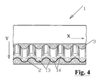
- Fig. 4 shows a view of the material web Fig. 1 with partially removed top layer and staggered longitudinal slots across the troughs.
- the material web 1 according to the invention is shown in enlarged longitudinal section.
- the material web 1 according to the invention has an extensible carrier element 2, an upper cover layer 3 and a lower cover layer 4.
- the stretchable support element 2 is a corrugated foil, preferably of 0.1 mm thick aluminum with 0.6 mm wave height.
- the upper cover layer 3 is a commercially available PUR sealant which covers the stretchable support element 2 at the upper vertexes 5 at least 0.1 mm
- the lower cover layer 4 is made of butyl rubber and covers the lower vertices 6 by about 0.3 mm.
- the total height H of the material web 1 according to the invention is 1.0 to 1.2 mm.
- the surface 7 of the upper cover layer 3 and the surface 8 of the lower cover layer 4 are flat and closed.
- Fig. 2 shows the material web 1 "in a state stretched by about 30% in the wave direction X.
- the total height H" is reduced by about 30%, contrary to the elongation.
- the stretchable support member 2 is only slightly wavy and the surface 7" of the upper cover layer 3 "and the surface 8" of the lower cover layer 6 "are still smooth but minimally wavy, so that an adhesion of the lower cover layer 6" on any surface problems is possible.
- Fig. 3 shows the material web 1 of the invention Fig. 1 ,
- a weather-resistant film 9 is laminated and on the lower cover layer 8 is wholly or partially applied an additional adhesive film 10, which is protected by a peelable protective film 11.
- the stretchable support layer 2 is provided with a coating 12 which increases the tensile strength.
- the coating 12 is formed as a heat-resistant PE non-woven with about 15 g / m 2 basis weight.
- Fig. 4 shows the material web 1 according to the invention with partially removed upper cover layer 3 and a stretchable support member 2 with additional staggered longitudinal slots 13 and 14, which allow an expanded mesh-like elongation of the material web 1 in this area in the direction Y transverse to the wave direction X.
Applications Claiming Priority (1)
| Application Number | Priority Date | Filing Date | Title |
|---|---|---|---|
| DE200820013677 DE202008013677U1 (de) | 2008-10-15 | 2008-10-15 | Plastisch verformbare Materialbahn |
Publications (2)
| Publication Number | Publication Date |
|---|---|
| EP2177686A2 true EP2177686A2 (fr) | 2010-04-21 |
| EP2177686A3 EP2177686A3 (fr) | 2012-04-04 |
Family
ID=40365707
Family Applications (1)
| Application Number | Title | Priority Date | Filing Date |
|---|---|---|---|
| EP09012784A Withdrawn EP2177686A3 (fr) | 2008-10-15 | 2009-10-09 | Matériau en bande plastiquement déformable |
Country Status (2)
| Country | Link |
|---|---|
| EP (1) | EP2177686A3 (fr) |
| DE (1) | DE202008013677U1 (fr) |
Families Citing this family (2)
| Publication number | Priority date | Publication date | Assignee | Title |
|---|---|---|---|---|
| PL2749708T3 (pl) * | 2012-12-27 | 2017-09-29 | Vkr Holding A/S | Fartuch do zastosowania w obróbce blacharskiej do struktury wnikającej w dach i sposób montażu fartucha na strukturze wnikającej w dach |
| DE102017122097A1 (de) * | 2017-09-25 | 2019-03-28 | Faist Chemtec Gmbh | Abdichtungselement und Verfahren zur Herstellung eines Abdichtungselements |
Citations (7)
| Publication number | Priority date | Publication date | Assignee | Title |
|---|---|---|---|---|
| DE3642063C2 (fr) | 1985-12-19 | 1991-03-21 | Braas Gmbh, 6370 Oberursel, De | |
| DE4404150C1 (de) | 1994-02-10 | 1995-05-24 | Braas Gmbh | Lüftungsband |
| WO1995031620A1 (fr) | 1994-05-18 | 1995-11-23 | V. Kann Rasmussen Industri A/S | Materiau plastiquement deformable pour la realisation d'une bande d'etancheite, en particulier d'une bande d'etancheite de toiture, et son procede de fabrication |
| WO1996006245A1 (fr) | 1994-08-24 | 1996-02-29 | Consolidated Alloys (N.Z.) Limited | Materiau de construction |
| DE19523834A1 (de) | 1995-06-30 | 1997-01-02 | Braas Gmbh | Plastisch von Hand verformbares Abdeckmaterial |
| DE19914071A1 (de) | 1999-03-27 | 2000-10-19 | Oskar Fleck | Plastisch verformbares Abdeckmaterial |
| DE10230552A1 (de) | 2002-07-05 | 2004-01-29 | Peter Brinkmann | Streckbares Bahnmaterial |
Family Cites Families (3)
| Publication number | Priority date | Publication date | Assignee | Title |
|---|---|---|---|---|
| DE19921339B4 (de) * | 1999-05-08 | 2009-05-20 | Bosig Gmbh | Selbstklebender Anschlussstreifen |
| DE19922202B4 (de) * | 1999-05-12 | 2004-02-26 | Wilhelm Röttger | Plastisch verformbare Materialbahn |
| DE10045002B4 (de) * | 2000-09-08 | 2004-12-23 | Röttger, Wilhelm | Plastisch verformbare Materialbahn |
-
2008
- 2008-10-15 DE DE200820013677 patent/DE202008013677U1/de not_active Expired - Lifetime
-
2009
- 2009-10-09 EP EP09012784A patent/EP2177686A3/fr not_active Withdrawn
Patent Citations (7)
| Publication number | Priority date | Publication date | Assignee | Title |
|---|---|---|---|---|
| DE3642063C2 (fr) | 1985-12-19 | 1991-03-21 | Braas Gmbh, 6370 Oberursel, De | |
| DE4404150C1 (de) | 1994-02-10 | 1995-05-24 | Braas Gmbh | Lüftungsband |
| WO1995031620A1 (fr) | 1994-05-18 | 1995-11-23 | V. Kann Rasmussen Industri A/S | Materiau plastiquement deformable pour la realisation d'une bande d'etancheite, en particulier d'une bande d'etancheite de toiture, et son procede de fabrication |
| WO1996006245A1 (fr) | 1994-08-24 | 1996-02-29 | Consolidated Alloys (N.Z.) Limited | Materiau de construction |
| DE19523834A1 (de) | 1995-06-30 | 1997-01-02 | Braas Gmbh | Plastisch von Hand verformbares Abdeckmaterial |
| DE19914071A1 (de) | 1999-03-27 | 2000-10-19 | Oskar Fleck | Plastisch verformbares Abdeckmaterial |
| DE10230552A1 (de) | 2002-07-05 | 2004-01-29 | Peter Brinkmann | Streckbares Bahnmaterial |
Also Published As
| Publication number | Publication date |
|---|---|
| EP2177686A3 (fr) | 2012-04-04 |
| DE202008013677U1 (de) | 2009-02-19 |
Similar Documents
| Publication | Publication Date | Title |
|---|---|---|
| EP2855793B1 (fr) | Élément de couverture de toiture | |
| DE202015006488U1 (de) | Feuchtesperre oder Mauersperrbahn | |
| EP2180126A2 (fr) | Bande d'étanchéité pouvant être étirée | |
| EP1474288B1 (fr) | Materiau en bande etirable | |
| AT502539A1 (de) | Verbundfolie | |
| EP3372133B1 (fr) | Ensemble de bande de montage et d'étanchéité | |
| DE102008051728B4 (de) | Plastisch verformbare Materialbahn | |
| EP2177686A2 (fr) | Matériau en bande plastiquement déformable | |
| DE19914071A1 (de) | Plastisch verformbares Abdeckmaterial | |
| DE102007031501B4 (de) | Dämmelement zur Isolierung von Bauelementen | |
| DE19804875C2 (de) | Selbstklebende Materialbahn | |
| DE19810434C1 (de) | Streifenförmige Materialbahn für eine First- oder Gratabdeckung sowie Verfahren und Vorrichtung zur Herstellung derselben | |
| EP3804977A1 (fr) | Élément support pour une bande de matière plastiquement déformable | |
| DE202013003354U1 (de) | Streckbares Dichtband | |
| EP1783282B1 (fr) | Arrangement protective pour des fondations des bâtiments | |
| EP2050890A1 (fr) | Bande d'étanchéité destinée à la fabrication de joints entre la toiture, comme les tuiles et éléments de construction | |
| DE202017001921U1 (de) | Dichtungsband | |
| DE202008013676U1 (de) | Streckbares Dichtband | |
| DE102008051743A1 (de) | Streckbares Dichtband | |
| DE202014100560U1 (de) | Mehrlagiges Band zur Abdichtung von durch Wände hindurchgeführte Rohre | |
| AT15715U1 (de) | Mehrlagige Dampfsperrschicht | |
| CH713621A2 (de) | Vorrichtung zum Erstellen eines Übergangs zwischen einer Sanitäreinrichtung und einer Vertikalfläche sowie ein Verfahren zum Erstellen eines solchen Übergangs und ein Feucht- oder Nassbereich mit einem solchen Übergang. | |
| DE202014105289U1 (de) | Gittergewebe für die Bewehrung von winkligen Treppenabschnitten einer Treppe | |
| DE102011107274B4 (de) | Streckbares Dichtungsband | |
| EP2789763A2 (fr) | Bande d'étanchéité étirable |
Legal Events
| Date | Code | Title | Description |
|---|---|---|---|
| PUAI | Public reference made under article 153(3) epc to a published international application that has entered the european phase |
Free format text: ORIGINAL CODE: 0009012 |
|
| AK | Designated contracting states |
Kind code of ref document: A2 Designated state(s): AT BE BG CH CY CZ DE DK EE ES FI FR GB GR HR HU IE IS IT LI LT LU LV MC MK MT NL NO PL PT RO SE SI SK SM TR |
|
| AX | Request for extension of the european patent |
Extension state: AL BA RS |
|
| PUAL | Search report despatched |
Free format text: ORIGINAL CODE: 0009013 |
|
| AK | Designated contracting states |
Kind code of ref document: A3 Designated state(s): AT BE BG CH CY CZ DE DK EE ES FI FR GB GR HR HU IE IS IT LI LT LU LV MC MK MT NL NO PL PT RO SE SI SK SM TR |
|
| AX | Request for extension of the european patent |
Extension state: AL BA RS |
|
| RIC1 | Information provided on ipc code assigned before grant |
Ipc: B32B 3/26 20060101ALI20120228BHEP Ipc: B32B 3/28 20060101ALI20120228BHEP Ipc: E04D 13/147 20060101AFI20120228BHEP |
|
| 17P | Request for examination filed |
Effective date: 20120919 |
|
| STAA | Information on the status of an ep patent application or granted ep patent |
Free format text: STATUS: THE APPLICATION IS DEEMED TO BE WITHDRAWN |
|
| 18D | Application deemed to be withdrawn |
Effective date: 20140501 |