EP2177686A2 - Plastically deformable web - Google Patents
Plastically deformable web Download PDFInfo
- Publication number
- EP2177686A2 EP2177686A2 EP09012784A EP09012784A EP2177686A2 EP 2177686 A2 EP2177686 A2 EP 2177686A2 EP 09012784 A EP09012784 A EP 09012784A EP 09012784 A EP09012784 A EP 09012784A EP 2177686 A2 EP2177686 A2 EP 2177686A2
- Authority
- EP
- European Patent Office
- Prior art keywords
- carrier element
- material web
- plastically deformable
- deformable material
- stretchable carrier
- Prior art date
- Legal status (The legal status is an assumption and is not a legal conclusion. Google has not performed a legal analysis and makes no representation as to the accuracy of the status listed.)
- Withdrawn
Links
Images

Classifications
-
- E—FIXED CONSTRUCTIONS
- E04—BUILDING
- E04D—ROOF COVERINGS; SKY-LIGHTS; GUTTERS; ROOF-WORKING TOOLS
- E04D13/00—Special arrangements or devices in connection with roof coverings; Protection against birds; Roof drainage; Sky-lights
- E04D13/14—Junctions of roof sheathings to chimneys or other parts extending above the roof
- E04D13/147—Junctions of roof sheathings to chimneys or other parts extending above the roof specially adapted for inclined roofs
-
- B—PERFORMING OPERATIONS; TRANSPORTING
- B32—LAYERED PRODUCTS
- B32B—LAYERED PRODUCTS, i.e. PRODUCTS BUILT-UP OF STRATA OF FLAT OR NON-FLAT, e.g. CELLULAR OR HONEYCOMB, FORM
- B32B3/00—Layered products comprising a layer with external or internal discontinuities or unevennesses, or a layer of non-planar form; Layered products having particular features of form
- B32B3/26—Layered products comprising a layer with external or internal discontinuities or unevennesses, or a layer of non-planar form; Layered products having particular features of form characterised by a particular shape of the outline of the cross-section of a continuous layer; characterised by a layer with cavities or internal voids ; characterised by an apertured layer
- B32B3/30—Layered products comprising a layer with external or internal discontinuities or unevennesses, or a layer of non-planar form; Layered products having particular features of form characterised by a particular shape of the outline of the cross-section of a continuous layer; characterised by a layer with cavities or internal voids ; characterised by an apertured layer characterised by a layer formed with recesses or projections, e.g. hollows, grooves, protuberances, ribs
Abstract
Description
Plastisch verformbare MaterialbahnPlastically deformable material web
Die Erfindung betrifft eine plastisch verformbare Materialbahn mit einem dehnbaren Trägerelement vorzugsweise zur Anwendung im Außenbereich von Bauwerken, wobei das Trägerelement gleichmäßige Wellen aufweist und die Wellentäler mit einer plastisch verformbaren Abdeckschicht ausgefüllt sind,The invention relates to a plastically deformable material web with a stretchable carrier element, preferably for use in the exterior of structures, wherein the carrier element has uniform waves and the troughs are filled with a plastically deformable covering layer,
Im Stand der Technik sind Materialbahnen bekannt, die beispielsweise unter dem Begriff "Blei-Ersatz" im Dachbereich angewendet werden. Sie haben die Aufgabe, Problemzonen wetterbeständig abzudichten, wie das beispielsweise bei Kamineinfassungen und Dachfensterschürzen der Fall ist. Um diese Funktion gut zu erfüllen, muss sich die Materialbahn leicht und gut dichtend an die jeweilige Dachkontur anformen lassen und soll vor allem den extremen Belastungen auf dem Dach standhalten.Material webs are known in the prior art, which are used for example under the term "lead replacement" in the roof area. Their task is to seal problem areas weather-resistant, as is the case for example with fireplace surrounds and skylights. In order to fulfill this function well, the material web must be able to be easily and tightly molded to the respective roof contour and, above all, to withstand the extreme loads on the roof.
Gängige Typen weisen deshalb eine plastisch verformbare Struktur in Form eines Streckgitters aus weichem Aluminium auf, das mit dem eigentlichen Dichtmaterial ummantelt ist. Entweder wird das Streckgitter mit der Dichtmasse beschichtet oder durch Aufwalzen mit der Dichtbahn verbunden.Common types therefore have a plastically deformable structure in the form of a stretched grid made of soft aluminum, which is coated with the actual sealing material. Either the expanded metal is coated with the sealant or connected by rolling with the sealing web.
Ein solches Bahnmaterial ist aus der
Ein weiteres Bahnmaterial ist aus
überlappende Anwendungen geeignet, bei denen zwei oder mehr Bahnen durch Verkleben miteinander verbunden werden sollen.overlapping applications where two or more webs are to be bonded together by gluing.
Des weiteren ist ein streckbares Bahnmaterial aus
Blei ist ein duktiles Material, d.h. es dehnt sich bei Zugbelastung irreversibel unter Verringerung des Querschnitts. Diese Duktilität wird bei den zuvor beschriebenen Bahnmaterialien, die Aluminium-Streckgitter als Trägermaterial verwenden, durch eine geometrische Verformung des Gitters ersetzt. Die Stege der Streckgitter müssen demzufolge relativ dick sein, um den Rückstellkräften der übrigen Schichten zu widerstehen, die nicht metallisch sondern im allgemeinen thermoplastisch oder auch duroplastisch sind.Lead is a ductile material, i. it expands irreversibly under tensile load while reducing the cross section. This ductility is replaced by geometrical deformation of the lattice in the previously described sheet materials using expanded aluminum lattices as a substrate. The webs of the expanded mesh must therefore be relatively thick to withstand the restoring forces of the other layers, which are not metallic but generally thermoplastic or thermosetting.
Gekreppte Alufolien ermöglichen große Dehnungen bei geringen Zugkräften, was neben der guten Verformbarkeit aber auch den Nachteil hat, dass eine so genannte Mikrofalte von etwa 0,1 mm auf 1 - 2 mm d.h. bis auf das 10- oder 20- fache gedehnt werden kann. Solche extremen örtlichen Dehnungen können nicht gleichmäßig auf die benachbarten Schichten übertragen werden, sondern es können unter der Folie Ablösungen oder Risse entstehen, die zu unerwünschten Kapillareffekten führen.Creped aluminum foils allow large strains with low tensile forces, which in addition to the good deformability but also has the disadvantage that a so-called micro-calf of about 0.1 mm to 1 - 2 mm, that can be stretched to 10 or 20 times. Such extreme local strains can not be uniform to the neighboring ones Layers are transferred, but it can cause delamination or cracks under the film, which lead to undesirable capillary effects.
Weiterhin ist es aus
auf etwa 0,3 mm. Dies ist naturgemäß ein sehr geringer Wert für ein starkbeanspruchtes Dachprodukt, sodass die untere Klebeschicht aus Sicherheitsgründen von vorne herein auf mindestens 1,5 mm ausgelegt werden muss. Zusätzlich sind diese ausgedünnten Stellen ohne Folienabdeckung der Bewitterung ausgesetzt, was die Kosten weiter erhöht, weil das Material insgesamt uv-beständig sein muss.to about 0.3 mm. This is by nature a very low value for a heavily stressed roof product, so that the lower adhesive layer must be designed from the outset to at least 1.5 mm for safety reasons. In addition, these thinned areas are exposed to weathering without film coverage, further increasing costs because the material must be UV-resistant overall.
Von MAGE Herzberg GmbH aus
Weiter ist in
Aufgabe der vorliegenden Erfindung ist es, eine quasi-homogene Materialbahn mit einer gleichmäßigen Wandstärke von etwa 0,5 mm bis 1,5 mm Stärke und geschlossenen Oberflächen zur Verfügung zu stellen, die sich von Hand ohne wesentliche Rückstellkräfte ähnlich einer dünnen Blei- oder Goldfolie dehnen lässt.Object of the present invention is to provide a quasi-homogeneous material web with a uniform wall thickness of about 0.5 mm to 1.5 mm thickness and closed surfaces available by hand without significant restoring forces similar to a thin lead or gold foil stretch.
Der Grundgedanke ist dabei, unter Verzicht auf Streckgitter oder geschlitzte Bleche als streckbare Metalleinlage eine durchgehend gewellte Metallfolie einzusetzen, deren Wellenhöhe so gering ist, dass die Wellentäler beidseitig vollständig mit Dichtmaterial ausgefüllt werden können, ohne dass die Gesamtstärke der Materialbahn zu groß und damit das Produkt unhandlich und unwirtschaftlich wird.The basic idea is to waive the use of expanded metal mesh or slotted sheets as stretchable metal insert to use a continuous corrugated metal foil whose wave height is so low that the wave troughs can be completely filled with sealing material on both sides, without the overall thickness of the material web is too large and thus the product becomes unwieldy and uneconomical.
Erfindungsgemäß wird vorzugsweise eine Aluminiumfolie von 0,10 mm Dicke mit ca. 0,6 mm hohen und 1,5 mm langen Wellen versehen, sodass sie eine Gesamthöhe von etwa 0,7 mm aufweist. Diese Wellenform entspricht in etwa der "Feinstwelle" bei der Wellpappenherstellung. Bei Verwendung einer Aluminiumfolie unter 0,1 mm ist auch eine noch kleinere Wellenform unter 0,3 mm Wellenhöhe und 0,8 mm Wellenlänge denkbar. Hiermit können insgesamt sehr dünne Materialbahnen von nur 0,5 mm Dicke hergestellt werden. Ein Verhältnis von Materialstärke zu Wellenhöhe 1:5 ist hierbei unkritisch. Die mögliche Dehnung ist dabei grundsätzlich sehr groß, im allgemeinen ist allerdings eine maximale Dehnfähigkeit von 50 % ausreichend.According to the invention, an aluminum foil of 0.10 mm thickness is preferably provided with shafts approximately 0.6 mm high and 1.5 mm long so that it has a total height of approximately 0.7 mm. This waveform roughly corresponds to the "fine wave" in corrugated board production. When using an aluminum foil of less than 0.1 mm, an even smaller waveform below 0.3 mm wave height and 0.8 mm wavelength is conceivable. Hereby altogether very thin material webs of only 0.5 mm thickness can be produced. A ratio of material thickness to wave height 1: 5 is not critical here. The possible stretching is included Generally very large, in general, however, a maximum elongation of 50% is sufficient.
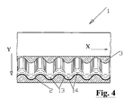
Für eine Materialbahn, die auf dem Dach eingesetzt werden soll, werden die Wellentäler auf der Oberseite vorzugsweise mit einem plastisch dehnbaren eingefärbten Dichtmaterial wie PUR-Dichtstoff ausgefüllt, der die Wellenberge noch um mindestens 0,1 mm überdeckt, und auf der Unterseite mit einem weichelastischen Kleber wie Butylkautschuk mit einer Silikonschutzfolie, welcher die unteren "Wellenberge" um etwa 0,3 mm überdeckt, sodass eine insgesamt 1,0 bis 1,2 mm dicke, geschlossene Materialbahn entsteht.For a material web to be used on the roof, the troughs on the top are preferably filled with a plastically stretchable colored sealing material such as PUR sealant, which covers the peaks still by at least 0.1 mm, and on the bottom with a soft elastic Adhesive such as butyl rubber with a silicone protective film, which covers the lower "peaks" by about 0.3 mm, so that a total of 1.0 to 1.2 mm thick, closed material web is formed.
Dieser Aufbau ermöglicht es, die einzelnen Schichten getrennt voneinander je nach Einsatzzweck und gewünschten Eigenschaften zu optimieren. So kann die obere Deckschicht aus einer Vielzahl von Dichtmassen gebildet werden wie z.B. Acryldispersion, Silikonkautschuk oder Schmelzkleber. Wenn für die farbliche Anpassung oder verbesserte Witterungsbeständigkeit eine weitere dünne Folie oder ein Lack aufgebracht wird oder wenn keine Witterungsbeständigkeit gefordert wird, kann die obere Deckschicht aus relativ preiswertem Material mit hohem Füllstoffanteil bestehen wie PUR-Schaum oder Wachs.This structure makes it possible to optimize the individual layers separately from one another depending on the intended use and desired properties. Thus, the top cover layer may be formed of a variety of sealants, such as e.g. Acrylic dispersion, silicone rubber or hot melt adhesive. If another thin film or varnish is applied for color matching or improved weatherability, or if weathering resistance is not required, the top surface layer may be made of relatively inexpensive high-content material such as PUR foam or wax.
Die untere Deckschicht ist vorzugsweise eine Kautschukklebemasse, es können jedoch auch Acrylkleber, Haftschmelzkleber, Bitumen oder spezielle reaktivierbare Klebesysteme verwendet werden. Wie auf der Oberseite ist es auch hier denkbar, die Wellentäler mit einem preiswerten nichtklebenden Material zu füllen und eine dünne Klebefolie, eventuell auch nur an den Rändern, darunter anzubringen. Ebenso kann ein Schmelzkleber eingesetzt werden, der mit Heißluft vor Ort verklebt werden kann. Zur besseren Haftung von niedrigviskosen Klebemassen wie z.B. Polymerbitumen ist vorgesehen, eine Schaumfolie auf die Unterseite der Tragschicht zu kaschieren.The bottom cover layer is preferably a rubber adhesive, but acrylic adhesives, hot melt adhesives, bitumen or special reactive adhesive systems may also be used. As on the top, it is also conceivable to fill the troughs with a cheap non-adhesive material and a thin adhesive film, possibly even at the edges, underneath to install. Likewise, a hot melt adhesive can be used, which can be glued on site with hot air. For better adhesion of low-viscosity adhesives, such as e.g. Polymer bitumen is intended to laminate a foam sheet on the underside of the support layer.
Die Tragschicht kann eine Folie von 20 µm bis 200 µm aus Aluminium, Kupfer, Blei oder einem anderen Metall sein. Die erforderliche Steifigkeit dieser Folie bemisst sich nach der Plastizität bzw. dem Rückstellvermögen der oberen und unteren Deckschichten. Sofern diese Materialien weich und leicht plastisch verformbar sind, kann die Tragschicht ebenfalls leicht und dünn sein. Z.B. kann eine 25 µm dicke typische Aluminium-Hausaltsfolie ausreichend sein für ein Korrosionsschutzband zur dampfdichten Umwickelung von Pipelines einschließlich Flanschen und Krümmungen.The support layer may be a film of 20 microns to 200 microns of aluminum, copper, lead or other metal. The required stiffness of this film is measured according to the plasticity or the resilience of the upper and lower cover layers. Unless these materials are soft and are easily plastically deformable, the support layer may also be light and thin. For example, a typical 25 μm thick aluminum foil may be sufficient for a corrosion protection tape for vapor-tight wrapping of pipelines including flanges and bends.
Um die Reißfestigkeit einer Folie zu erhöhen, die ansonsten alle Funktionen erfüllen würde, kann dieselbe auch mit einer Kunststoff-Folie, einem Kunststoff-Vlies oder anderen organischen Fasern verstärkt werden. Grundsätzlich kann die Tragschicht auch aus einer nichtmetallischen, notfalls bedampften Folie wie z.B. Polyester oder Acrylat bestehen, um beispielsweise als Dampfsperre zu dienen.In order to increase the tear strength of a film that would otherwise perform all functions, it can also be reinforced with a plastic film, a plastic non-woven or other organic fibers. In principle, the base layer can also be made of a non-metallic, if necessary vapor-deposited, film such as e.g. Polyester or acrylate exist, for example, to serve as a vapor barrier.
Selbst ein Vlies oder Gewebe ist als Tragschicht denkbar, wenn die Deckschichten keine Rückstellkräfte erzeugen und in ihrem gedehnten Zustand ohne Stützkräfte verharren oder wenn die Verklebung auf der Unterseite für eine ausreichende Fixierung sorgt. Es ist beispielsweise denkbar, ein PP-Vlies von 30 g/m2 Flächengewicht als Tragschicht beiderseits mit Polymerbitumen auszufüllen.Even a fleece or fabric is conceivable as a base layer when the outer layers produce no restoring forces and remain in their stretched state without support forces or when the bond on the bottom provides sufficient fixation. It is conceivable, for example, to fill a PP nonwoven of 30 g / m 2 basis weight as a base layer on both sides with polymer bitumen.
Weiterhin ist es möglich, die gewellte Tragschicht quer zu den Wellen ganz oder teilweise mit versetzten Schlitzen zu versehen, sodass eine streckgitterförmige Dehnung quer zu der zuvor beschriebenen Streckrichtung möglich ist. In besonderen Fällen können aus dem Bahnmaterial auch Formteile wie z.B. Schürzen für Dachfenster hergestellt werden.Furthermore, it is possible to provide the corrugated support layer transversely to the waves wholly or partially offset slots, so that an expanded-mesh-like elongation transverse to the previously described stretching direction is possible. In special cases, molded parts such as e.g. Aprons for roof windows are made.
Weitere Einzelheiten und Merkmale der Erfindung sind nicht nur den Ansprüchen, sondern auch aus den nachstehenden Zeichnungen für sich und/oder in Kombination zu entnehmen.Further details and features of the invention can be taken not only from the claims, but also from the following drawings alone and / or in combination.
Es zeigen:Show it:
In
Claims (11)
Applications Claiming Priority (1)
| Application Number | Priority Date | Filing Date | Title |
|---|---|---|---|
| DE200820013677 DE202008013677U1 (en) | 2008-10-15 | 2008-10-15 | Plastically deformable material web |
Publications (2)
| Publication Number | Publication Date |
|---|---|
| EP2177686A2 true EP2177686A2 (en) | 2010-04-21 |
| EP2177686A3 EP2177686A3 (en) | 2012-04-04 |
Family
ID=40365707
Family Applications (1)
| Application Number | Title | Priority Date | Filing Date |
|---|---|---|---|
| EP09012784A Withdrawn EP2177686A3 (en) | 2008-10-15 | 2009-10-09 | Plastically deformable web |
Country Status (2)
| Country | Link |
|---|---|
| EP (1) | EP2177686A3 (en) |
| DE (1) | DE202008013677U1 (en) |
Families Citing this family (2)
| Publication number | Priority date | Publication date | Assignee | Title |
|---|---|---|---|---|
| CN103899053B (en) * | 2012-12-27 | 2017-11-10 | Vkr控股公司 | Skirt component and its installation method |
| DE102017122097A1 (en) * | 2017-09-25 | 2019-03-28 | Faist Chemtec Gmbh | Sealing element and method for producing a sealing element |
Citations (7)
| Publication number | Priority date | Publication date | Assignee | Title |
|---|---|---|---|---|
| DE3642063C2 (en) | 1985-12-19 | 1991-03-21 | Braas Gmbh, 6370 Oberursel, De | |
| DE4404150C1 (en) | 1994-02-10 | 1995-05-24 | Braas Gmbh | Ventilating strip in building |
| WO1995031620A1 (en) | 1994-05-18 | 1995-11-23 | V. Kann Rasmussen Industri A/S | A plastically deformable flashing material, in particular for roof flashing purposes and a method of manufacturing such a material |
| WO1996006245A1 (en) | 1994-08-24 | 1996-02-29 | Consolidated Alloys (N.Z.) Limited | Building construction material |
| DE19523834A1 (en) | 1995-06-30 | 1997-01-02 | Braas Gmbh | Plastic material that can be deformed by hand |
| DE19914071A1 (en) | 1999-03-27 | 2000-10-19 | Oskar Fleck | Cover strip for exterior building work comprises corrugated metal cover layer filled on underside with butyl rubber adhesive sealant |
| DE10230552A1 (en) | 2002-07-05 | 2004-01-29 | Peter Brinkmann | Stretchable web material |
Family Cites Families (3)
| Publication number | Priority date | Publication date | Assignee | Title |
|---|---|---|---|---|
| DE19921339B4 (en) * | 1999-05-08 | 2009-05-20 | Bosig Gmbh | Self-adhesive connection strip |
| DE19922202B4 (en) * | 1999-05-12 | 2004-02-26 | Wilhelm Röttger | Plastically deformable material web |
| DE10045002B4 (en) * | 2000-09-08 | 2004-12-23 | Röttger, Wilhelm | Plastically deformable material web |
-
2008
- 2008-10-15 DE DE200820013677 patent/DE202008013677U1/en not_active Expired - Lifetime
-
2009
- 2009-10-09 EP EP09012784A patent/EP2177686A3/en not_active Withdrawn
Patent Citations (7)
| Publication number | Priority date | Publication date | Assignee | Title |
|---|---|---|---|---|
| DE3642063C2 (en) | 1985-12-19 | 1991-03-21 | Braas Gmbh, 6370 Oberursel, De | |
| DE4404150C1 (en) | 1994-02-10 | 1995-05-24 | Braas Gmbh | Ventilating strip in building |
| WO1995031620A1 (en) | 1994-05-18 | 1995-11-23 | V. Kann Rasmussen Industri A/S | A plastically deformable flashing material, in particular for roof flashing purposes and a method of manufacturing such a material |
| WO1996006245A1 (en) | 1994-08-24 | 1996-02-29 | Consolidated Alloys (N.Z.) Limited | Building construction material |
| DE19523834A1 (en) | 1995-06-30 | 1997-01-02 | Braas Gmbh | Plastic material that can be deformed by hand |
| DE19914071A1 (en) | 1999-03-27 | 2000-10-19 | Oskar Fleck | Cover strip for exterior building work comprises corrugated metal cover layer filled on underside with butyl rubber adhesive sealant |
| DE10230552A1 (en) | 2002-07-05 | 2004-01-29 | Peter Brinkmann | Stretchable web material |
Also Published As
| Publication number | Publication date |
|---|---|
| DE202008013677U1 (en) | 2009-02-19 |
| EP2177686A3 (en) | 2012-04-04 |
Similar Documents
| Publication | Publication Date | Title |
|---|---|---|
| EP2855793B1 (en) | Roof covering element | |
| EP2180126A2 (en) | Stretchable sealing tape | |
| EP1474288B1 (en) | Flexible band material | |
| DE202015006488U1 (en) | Moisture barrier or wall barrier | |
| AT502539A1 (en) | COMPOSITE FILM | |
| EP3372133B1 (en) | Sealing and mounting tape assembly | |
| DE102008051728B4 (en) | Plastically deformable material web | |
| EP2177686A2 (en) | Plastically deformable web | |
| DE19914071A1 (en) | Cover strip for exterior building work comprises corrugated metal cover layer filled on underside with butyl rubber adhesive sealant | |
| DE102007031501B4 (en) | Insulating element for insulating components | |
| DE19804875C2 (en) | Self-adhesive material web | |
| DE19810434C1 (en) | Ridge capping strip | |
| EP3804977A1 (en) | Carrier element for a plastically deformable material sheet | |
| DE202013003354U1 (en) | Stretchable sealing tape | |
| EP1783282B1 (en) | Protective arrangement for a foundation structure | |
| EP2050890A1 (en) | Sealing band for producing seals between roofing parts, such as roof tiles and structural parts | |
| DE202017001921U1 (en) | sealing tape | |
| DE202008013676U1 (en) | Stretchable sealing tape | |
| DE102008051743A1 (en) | Stacked sealing tape has wavy metallic surface layer of aluminum foil and glue layer, where wave height is smaller than half overall height of sealing tape | |
| DE202014100560U1 (en) | Multi-layer tape for sealing pipes passed through walls | |
| AT15715U1 (en) | Multi-layer vapor barrier | |
| CH713621A2 (en) | Device for creating a transition between a sanitary device and a vertical surface and a method for creating such a transition and a wet or wet area with such a transition. | |
| DE202014105289U1 (en) | Mesh fabric for the reinforcement of angled stair sections of a staircase | |
| DE102011107274B4 (en) | Stretchable sealing tape | |
| EP2789763A2 (en) | Stretchable sealing tape |
Legal Events
| Date | Code | Title | Description |
|---|---|---|---|
| PUAI | Public reference made under article 153(3) epc to a published international application that has entered the european phase |
Free format text: ORIGINAL CODE: 0009012 |
|
| AK | Designated contracting states |
Kind code of ref document: A2 Designated state(s): AT BE BG CH CY CZ DE DK EE ES FI FR GB GR HR HU IE IS IT LI LT LU LV MC MK MT NL NO PL PT RO SE SI SK SM TR |
|
| AX | Request for extension of the european patent |
Extension state: AL BA RS |
|
| PUAL | Search report despatched |
Free format text: ORIGINAL CODE: 0009013 |
|
| AK | Designated contracting states |
Kind code of ref document: A3 Designated state(s): AT BE BG CH CY CZ DE DK EE ES FI FR GB GR HR HU IE IS IT LI LT LU LV MC MK MT NL NO PL PT RO SE SI SK SM TR |
|
| AX | Request for extension of the european patent |
Extension state: AL BA RS |
|
| RIC1 | Information provided on ipc code assigned before grant |
Ipc: B32B 3/26 20060101ALI20120228BHEP Ipc: B32B 3/28 20060101ALI20120228BHEP Ipc: E04D 13/147 20060101AFI20120228BHEP |
|
| 17P | Request for examination filed |
Effective date: 20120919 |
|
| STAA | Information on the status of an ep patent application or granted ep patent |
Free format text: STATUS: THE APPLICATION IS DEEMED TO BE WITHDRAWN |
|
| 18D | Application deemed to be withdrawn |
Effective date: 20140501 |